

Page 1
for Surround
Model 78 Central Controller and
Model 79 Control Console
User Guide
Issue 5, January 2004
This User Guide is applicable for systems consisting of:
Model 78: serial number M78-00151 and later;
Model 79: M79-00151 and later
THX® pm3
approved
© 2004 by Studio Technologies, Inc., all rights reserved
www.studio-tech.com
50093-0104, Issue 5
Page 2

This page intentionally left blank.
Page 3

for Surround
Table of Contents
Introduction ................................................................... 5
Installation .................................................................... 9
Configuration ................................................................13
Operation ......................................................................27
Technical Notes ............................................................31
Specifications ...............................................................38
Appendix A ...................................................................39
MIDI Messages ........................................................40
Block Diagrams
Model 78 Central Controller
Model 79 Control Console
Model 78/79 User Guide Issue 5, January 2004
Studio Technologies, Inc. Page 3
Page 4

for Surround
This page intentionally left blank.
Issue 5, January 2004 Model 78/79 User Guide
Page 4 Studio Technologies, Inc.
Page 5

for Surround
Introduction
What This User Guide Covers
This User Guide is designed to assist you
when installing and using the Model 78
Central Controller and the Model 79
Control Console.
StudioComm for Surround
Once exclusively the domain of major motion picture studios and large production
facilities, the recording, mixing, editing,
and distribution of multichannel “surround”
audio material has become much more
prevalent. To handle these tasks, the ability
to effectively monitor multichannel sources
has become imperative for more and more
facilities. Studio Technologies has addressed this need with the StudioComm for
Surround Model 78 Central Controller and
Model 79 Control Console. The system is
perfect for 8-channel “7.1” applications,
including adding 7.1 monitoring capability to disk-based recording systems. It’s
also ideal for upgrading a post-production,
mastering, or broadcast facility to support
multichannel monitoring. The StudioComm
for Surround Model 78 and Model 79
combination is THX® pm3 approved.
The system’s core design goals were
audio quality and ease of use. Designed
to support the most sophisticated audio
requirements, the signal path was optimized for sonic quality. The operator features and controls were carefully selected
to enhance usability and minimize the
learning curve. For the first time, advanced
multichannel monitoring features such as
source selection, level control, downmix,
and bass management are available in a
compact, sonically excellent, and costeffective system.
A StudioComm for Surround system starts
with the Model 79 Control Console, a
compact, comfortable “command center,”
that is designed to reside at the operator’s
location. Using a single 9-pin cable, the
Model 79 connects to the Model 78 Central
Controller. The Model 78 occupies just one
rack space and allows connection of two
8-channel inputs and an 8-channel monitor
output. With the StudioComm for Surround
system any audio console, disk-based
recording system, or broadcast facility can
have a complete 7.1 multichannel monitor
system.
Model 78 Central Controller
The Model 78 Central Controller is a
single rack-space unit that contains analog, digital, and power supply electronics.
Two 8-channel analog sources can be
connected. In many applications the first
input, Surround A, will be connected to a
multichannel output on an audio console
or digital audio workstation. The second
input, Surround B, will be connected to a
playback device, such as a multitrack tape
recorder or disk storage system. For film or
video post applications Surround A would
be considered the direct source, while
Surround B would be considered the playback source. For flexibility, the inputs are
compatible with balanced or unbalanced
signals having a nominal level range of
–12 dBV to +6 dBu. Fifteen-turn trim potentiometers are used to precisely calibrate
the input signals.
A sophisticated bass management function is integral to the Model 78’s design.
The overall goal of bass management is
very simple: ensure that the entire audio
bandwidth of all channels can be accurately monitored. Many loudspeaker systems
have inherent low-frequency limitations,
Model 78/79 User Guide Issue 5, January 2004
Studio Technologies, Inc. Page 5
Page 6
for Surround
preventing a true picture of the source
material from being presented. To overcome
this, the low-frequency energy from the
seven main channels can be separated and
then routed to the subwoofer loudspeaker.
From the factory a general-purpose bass
management configuration is implemented.
In most cases this will provide highly effective monitoring. To support specialized
applications a technician can revise many
of the bass management parameters, including disabling bass management entirely.
The Model 78 provides an 8-channel monitor output to connect to the loudspeaker
system. The outputs are electronically balanced and designed for connection to audio
power amplifiers or amplified loudspeakers. Protection circuitry provides power-up
and power-down protection. Note that while
each of the two surround inputs has an LFE
channel associated with it, the monitor output designates a subwoofer, rather than an
LFE, output. This terminology was carefully
selected to highlight the fact that the output
channel designated for connection to the
subwoofer loudspeaker may have more
than just LFE content. The bass management function redirects low-frequency energy from the main channels, combining it
with the LFE content before routing to the
subwoofer output.
Audio input and output connections are
made using three 25-pin D-subminiature
connectors. The Model 78’s audio path features analog switches for input source selection and digitally controlled analog gain
circuits for monitor level control. One 9-pin
D-subminiature connector is used to connect the Model 78 to the Model 79 Control
Console. A second 9-pin “D-sub” connector
is used to interface remote control signals
with the Model 78. An 8-bit microcontroller
provides the logic “horsepower” for the
Model 78. AC mains power is connected
directly to the Model 78, which is factory
selected for 100, 120, or 220/240 V operation. The internal power supply utilizes two
toroidal mains transformers for quiet audio
operation.
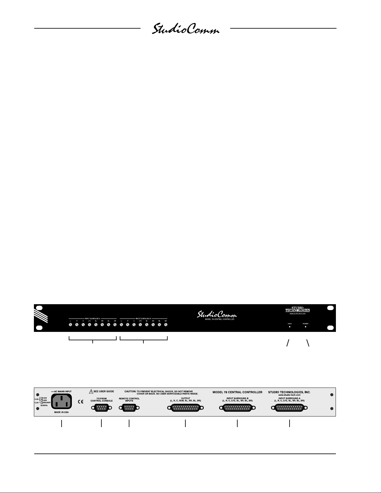
Figure 1. Model 78 Central Controller Front Panel
Input Surround A
trim pots
Figure 2. Model 78 Central Controller Back Panel
AC mains
connection
Issue 5, January 2004 Model 78/79 User Guide
Page 6 Studio Technologies, Inc.
To/from
Model 79
Control Console
Input Surround B
trim pots
Remote control
connections
Surround monitor
output connections
Input Surround B
connections
Data
active LED
Input Surround A
connections
present LED
Power
Page 7
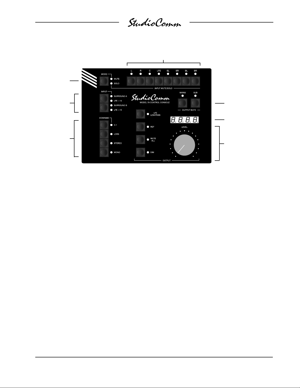
Mute/solo
mode select
for Surround
Input mute/solo
Input sources
Downmix
Figure 3. Model 79 Control Console Front Panel
Model 79 Control Console
The Model 79 Control Console is a compact
self-contained unit designed to be located
at the operator’s position. It allows fingertip
control of all monitoring parameters. Numerous LED indicators provide complete status
information. A 4-digit numeric display indicates the monitor output level in real time.
A major strength of the Model 79 is its ability
to configure, under software control, a number of operating parameters. For example,
during the installation and calibration process, the relative levels of the monitor output channels can be adjusted. This helps to
ensure that maximum performance from the
loudspeaker system can easily be obtained.
All configuration parameters are stored in
nonvolatile memory.
The Model 79 provides two buttons and associated LEDs for selection of the surround
source to be monitored. While in most cases
only one input source will be monitored at
Mains/sub output mute
Monitor output
level display
Monitor Output
• LFE low-pass filter
• Reference level
• Mute all
• Dim
• Rotary level control
a time, both inputs can be selected for
simultaneous monitoring. This feature can
be useful for creating a rough mix from
the two sources. It is also a fast, effective
means of making a “seat-of-the-pants”
check on the phase relationship between
synchronized signals. For compatibility with
some cinema formats, two buttons and
associated LEDs allow +10 dB of gain to
be added to each input’s LFE channel.
Four downmix modes allow the selected
source to be checked for compatibility
among different formats. The downmix
modes, 5.1, LCRS, Stereo, and Mono,
were implemented primarily for use in
sound-for-picture applications. As such,
from the factory the downmix coefficients
were selected to be effective in these environments. However, a technician can easily
change each downmix mode to meet the
specific needs of a facility or audio format.
Model 78/79 User Guide Issue 5, January 2004
Studio Technologies, Inc. Page 7
Page 8

for Surround
An LFE low-pass filter function is provided
as a means of checking the audio content
in the selected input’s LFE channel. The
operator can enable and disable the function as required, helping to ensure that the
proper signals are being mixed to the LFE
channel. Having the correct mix content is
critical as the LFE channel is often bandrestricted during distribution.
The monitor output level can be controlled
by way of a large, easy-to-use rotary
control. The “curve” or “taper” of the level
control can be configured to match an operator’s preference. The choices available
are true logarithmic and modified logarithmic. The level control auto mute-all function allows the monitor output channels to
automatically mute whenever the rotary
level control is in its fully counterclockwise
(minimum) position. This is useful in applications such as broadcast. By using the
reference level function, the monitor output
level can set to a preconfigured value. This
is provided for applications that require a
specific monitor level to be quickly selected. The reference level is easily configured
by taking an electronic “snapshot” of the
position of the rotary level control. For operator confirmation, the 4-digit LED readout displays the level of the monitor output.
For operator convenience, the dim function
allows the monitor output level to be
reduced by a fixed dB amount. The muteall function allows one button to simultaneously mute all eight monitor output
channels. The input mute/solo section
provides individual input channel control.
One push-button switch sets the operating mode for either mute or solo. In the
mute mode, individual input channels can
be muted as required. In the solo mode,
one channel can be monitored while the
others are automatically muted. Depend-
ing on the configuration, multiple channels
can be simultaneously selected for “solo
ing.” The flexibility of having both input mute
and input solo available allows an operator
to quickly select the most comfortable and
productive operating mode.
Two output mute functions are also provid
ed. One button allows the seven main output channels to be directly muted. A second
button allows the subwoofer monitor output
channel to be muted. The output mute function, along with the input mute/solo function, allows an operator complete flexibility
when checking an input source and its path
to the loudspeaker system. These mute and
solo resources are crucial in a multichannel environment, especially when signals
are passing through a bass management
system.
The Model 79 Control Console connects
to, and is powered by, the Model 78 Central
Controller. The Model 79 generates MIDI
system-exclusive messages to control the
Model 78. Remote-control signals connected to the Model 78 Central Controller
are routed to the Model 79 via pins in the
interconnecting cable.
Remote Control Capability
For flexibility, the StudioComm for Surround
system is designed to easily integrate with
recording consoles, studio communications
systems, and film motion-control electron
ics. Three remote-control input functions
are provided: mute all, dim, and input
source override. By providing access to the
StudioComm’s mute all and dim functions,
talkback or slate activity from an audio
console or other communications system
can control the monitor output level. The
input source override function is provided
expressly for film post applications, allowing
automatic switching of the StudioComm’s
Issue 5, January 2004 Model 78/79 User Guide
Page 8 Studio Technologies, Inc.
Page 9

for Surround
input source whenever the mode of a recording system changes between playback
and record. This function, often referred to
as PEC/direct switching, allows accurate
monitoring during dialog replacement or
other overdub sessions.
Channel Assignment and Routing
The Model 78/Model 79 combination is
expressly designed to support 8-channel
7.1 monitoring, with the input channels designated as left, right, center, LFE, surround
left, surround right, back left, and back right.
While it is anticipated that this channel arrangement will be quite common, the channels can obviously be used in alternative
arrangements. Using the system with 5.1
sources is perfectly acceptable.
While the StudioComm for Surround system
for multichannel monitoring will do many
wonderful things, it is not designed to selectively route input signals to different output
channels. The input-channel-to-output-channel relationship is maintained. A signal that
arrives on the SL channel of the Surround
B input will, when selected, output only on
the SL channel of the monitor output. Any
rerouting of the input signals must be done
prior to their connection to the StudioComm
for Surround system. This should not be a
drawback in most facilities, but it is important to highlight this fact.
Installation
In this section you will be installing the
Model 78 Central Controller in an equipment rack. Audio input and monitor output
connections will be made. A location will be
selected for the Model 79 Control Console
and it will be connected to the Model 78. If
required, external equipment will be interfaced to the remote control inputs. AC mains
power will be connected to the Model 78.
System Components
The shipping carton contains one each of
the following: Model 78 Central Controller, Model 79 Control Console, 20-foot
(6.1 m) 9-pin D-sub interconnecting cable,
and user guide. Units destined for North
America also include an AC mains cord.
Your dealer or distributor should provide
an AC mains cord for non-North American
destinations.
Mounting the Model 78
The Model 78 Central Controller requires
one space in a standard 19-inch (48.3 cm)
equipment rack. Select a location that is
convenient to both the analog audio sig
nals and the Model 79 Control Console. A
20-foot (6.1 m) cable is supplied to connect the Model 78 to the Model 79. You
can supply your own interconnecting cable,
however 50 feet (15.3 m) is the recommended maximum length. Secure the
Model 78 into the equipment rack using
two mounting screws per side.
-
Audio Connections
Audio signal connections are made by way
of three 25-pin D-sub connectors, located
on the Model 78’s back panel. Three cable
harnesses, each with a 25-pin D-sub plug
(male) on one end and the desired connectors on the other end, are necessary.
These cable harnesses are not normally
supplied by Studio Technologies. Note that
our friends in some locations may use the
term “loom” instead of harness.
The wiring scheme used by the D-subs
complies with the one made familiar by
TASCAM® with their DA-88® product. Wiring harnesses prepared for connecting to
the surround inputs are identical to DA-88style input harnesses. A wiring harness
Model 78/79 User Guide Issue 5, January 2004
Studio Technologies, Inc. Page 9
Page 10

for Surround
prepared for the monitor outputs is identical to that of a DA-88-style output harness.
Please refer to Figures 4 and 5 for the
exact connection details. Note that unlike
a DA-88-style harness, the Model 78’s
D-sub connectors use 4-40 threads. This
complies with the original design standard
for D-subminiature connectors.
Unless there’s a special need, it may be
cost and time effective for you to purchase
commercially made cable harnesses. Let
the large market for DA-88-style cabling
help you painlessly install your system!
Surround Inputs
The connectors labeled Input Surround A
and Input Surround B are used to interface
with the 16 input circuits. Please refer to
Figure 4 for details on the exact “pin out”
of the D-sub connectors. Each input circuit is electronically balanced. They are
intended for connection to balanced or
unbalanced sources with nominal signal
levels of –12 dBV to +6 dBu. A 15-turn
trim potentiometer is associated with each
input, allowing the input sensitivity to be
adjusted to match the source’s level. The
configuration section of this guide provides
details on using the trim pots.
Balanced sources should be wired so that
signal high is connected to +, signal low to
–, and shield to the shield connection. With
an unbalanced source, connect signal high
to the + connection, and shield to both the
– and the shield connections. If connecting
to an unbalanced source in this manner results in hum or noise, try connecting signal
high to +, and shield to –; leave the shield
connection unterminated.
Signal Signal
Connections High (+) Low (–) Shield
L 24 12 25
R 10 23 11
C 21 9 22
LFE 7 20 8
SL 18 6 19
SR 4 17 5
BL 15 3 16
BR 1 14 2
Notes: 1) Connector type on Model 78 is 25-pin D-subminiature
female. Installer must provide plug (male). Connector
uses 4-40 threaded inserts for locking with mating plug.
2) Wiring scheme follows TASCAM DA-88 convention.
Standard DA-88-type wiring harnesses are directly
compatible, with the exception of 4-40 screw threads
being required.
Figure 4. Connections for Inputs Surround A
and Surround B
Signal Signal
Connections High (+) Low (–) Shield
L 24 12 25
R 10 23 11
C 21 9 22
SUB 7 20 8
SL 18 6 19
SR 4 17 5
BL 15 3 16
BR 1 14 2
Notes: 1) Connector type on Model 78 is 25-pin D-subminiature
female. Installer must provide plug (male). Connector
uses 4-40 threaded inserts for locking with mating plug.
2) Wiring scheme follows TASCAM DA-88 convention.
Standard DA-88-type wiring harnesses are directly
compatible, with the exception of 4-40 screw threads
being required.
Figure 5. Connections for Monitor Output
It is highly recommended that at least one
of the surround inputs be wired by way
Issue 5, January 2004 Model 78/79 User Guide
Page 10 Studio Technologies, Inc.
Page 11

for Surround
of an audio patch bay. This will allow the
channels associated with that input source
to be easily rerouted. While signals generated within a facility will normally follow a
specific format, such as L, R, C, LFE, SL,
SR, BL, and BR, it is possible that media
provided by an outside facility will follow a
different one.
Monitor Output
The connector labeled output provides
access to the 8-channel monitor output.
Please refer to Figure 5 for details on the
exact “pin out” of the D-sub connector.
The monitor output channels are intended
for connection to audio amplifiers associated with monitor loudspeakers, or to the
inputs of loudspeakers that contain integrated amplifiers. The monitor outputs are
electronically balanced and capable of
driving balanced or unbalanced loads of
600 ohms or greater. While balanced operation is preferred, unbalanced operation
does not pose a problem. To connect to an
unbalanced load connect the + terminal
as signal high, and both the – and shield
as the signal low/shield. For optimal unbalanced operation, it is important to connect
both – and shield together directly on the
D-sub plug, not at the other end of the
harness.
Note that while the Model 78’s electronically balanced output circuits are capable
of driving loads of 600 ohms or greater,
the output level will drop slightly as the
load impedance approaches 600 ohms.
A 0.5 dB difference in output level can be
expected as the load impedance changes
from 10 k ohms to 600 ohms.
Remote Control Inputs
Support is provided for three remote control input functions: mute all, dim, and input
select. The inputs use logic gates, “pulled
up” to +5 V by way of resistors, which are
active when brought to the logic low state.
Inputs of this type are commonly referred
to as GPI inputs. While the input circuitry
is protected from over-current and static
(ESD) discharge, care should be taken to
prevent nasty signals from reaching them.
The inputs are active only when held in
the low state; they can’t be configured to
change state (“latch”) in response to a
logic pulse.
The connector labeled Remote Control
Inputs on the back panel of the Model 78
is used to interface with the remote control
inputs. Refer to Figure 6 for exact connection details. Note that pin 1 (Shield) and
pin 9 (Remote Control Common) are electrically identical. In addition to connecting
to system common, they connect to the
Model 78’s chassis and mains earth connection. For convenience, the shield of the
interconnecting cable should be connected
to pin 1 (Shield), while the return signals of
the remote control sources should connect
to pin 9 (Remote Control Common).
Note that although the remote control connections are physically made to the D-sub
on the Model 78’s back panel, the remote
control input circuitry is actually located in
the Model 79 Control Console. Conductors in the cable linking the Model 78 to the
Model 79 route the remote control signals
to the actual input circuitry.
Model 78/79 User Guide Issue 5, January 2004
Studio Technologies, Inc. Page 11
Page 12
for Surround
Pin Signal
1 Shield
5 Remote Mute All
6 Remote Dim
7 Remote Input Select
9 Remote Control Common
Notes: 1) Connector type on Model 78 is 9-pin D-subminiature
female. Installer must provide plug (male). Connector
uses 4-40 threaded inserts for locking with mating plug.
Figure 6. Connector Pin Out for Remote Control
Inputs
Connecting the Model 78 to
the Model 79
A cable with 9-pin D-sub plugs (males)
on each end is used to interconnect the
Model 78 Central Controller with the
Model 79 Control Console. A 20-foot (6.1meter) cable is provided with each system.
The connector labeled To/From Control
Console on the back panel of the Model 78
is used to connect to the Model 79.
Should a cable of different length be required, it should be wired in a one-to-one
fashion for all 9 pins. Pin 1 carries signal
common, and must be connected at both
ends. A shield connection for the cable
should be connected to pin 1 on the Model
78’s end. For best performance the cable
generally should not exceed 50 feet (15.3
meter) in length. The reality is that a cable
much longer in length should work correctly, as long as an excellent-quality cable is
utilized. We define “excellent” as extensive
shielding along with very low capacitance.
The low cable capacitance is important
as it limits the amount of data-signal
waveform distortion. As far as an actual
maximum length, just test and see how far
away you can go—if it works, it works!
AC Mains Power
The Model 78 is internally configured to
operate from either nominal 100, 120,
or 220/240 V, 50/60 Hz. Units shipped to
North America are factory selected for
120 V operation. Units bound for Japan
are generally selected for 100 V, while
our friends “down under” and in Europe
receive units set for 220/240 V. Before
connecting the Model 78 to AC mains
power, check that it is configured to match
the local mains voltage. Look on the back
panel (adjacent to the power entry connector) for the factory-configured voltage.
Note that an incorrect configuration could
prevent operation, or cause damage to the
unit. Should it be necessary to change the
unit’s operating voltage it must be performed only at the factory, or by a factoryauthorized service technician.
The Model 78 uses an IEC-standard
connector to mate with the AC mains
cord. The wire colors in the AC mains
cord should conform to the internationally
recognized CEE color code and must
be wired accordingly:
Connection Wire Color
Neutral (N) Light Blue
Line (L) Brown
Protective Earth (E) Green/Yellow
Safety Warning: The Model 78 does not
contain an AC mains disconnect switch.
As such, the AC mains cord plug serves
as the disconnection device. Safety
considerations require that the plug and
associated outlet be easily accessible to
allow rapid disconnection of AC mains
power should it prove necessary.
Issue 5, January 2004 Model 78/79 User Guide
Page 12 Studio Technologies, Inc.
Page 13

for Surround
As soon as AC mains power is applied, the
Model 78’s power present LED will light.
The Model 79 will go through a power-up
sequence, lighting each LED in secession.
The Model 79’s software revision level will
also display momentarily. The data active
LED on the Model 78 will briefly light upon
completion of the Model 79’s power-up
sequence.
Configuration
After the physical installation has been
completed, several configuration issues
must be addressed. On the Model 78 the
surround inputs must be calibrated using
the trim potentiometers. The operating parameters of the system should be set using
the Model 79 Control Console’s configuration mode. Using the Model 79’s calibration
mode, output channel level offsets can be
configured if desired.
Input Level Calibration
Sixteen 15-turn trim potentiometers are
located on the front panel of the Model
78 Central Controller. Taking time to carefully adjust the trim pots will ensure that
accurate monitoring can take place. Each
trim pot allows input signals with a nominal
level of –12 dBV to +6 dBu to be utilized.
With care, it’s easy to calibrate the surround inputs to within one-quarter of a dB
of the desired value.
Procedure
This procedure will calibrate the surround
input channels. The trim pots will be adjusted in groups corresponding to their
associated input source.
1. Begin by turning the audio amplifiers
or amplified speakers to their off state.
This will protect the loudspeakers and
the operator’s ears from possible
damage.
2. Rotate the level control on the Model
79 to the fully clockwise (maximum)
position.
3. Using the Model 79 Control console,
select Surround A as the input source.
4. On the Model 78, connect the audio
level meter to the left channel of the
monitor output.
5. Confirm that the audio source’s left
channel is generating a steady signal
at precisely its reference level.
6. Observing the level meter, adjust trim L
for Surround A to give the desired level
at monitor output L. This level may be
+4 dBu, +14 dBu, or some other value
depending on the configuration of the
output level range.
7. Disconnect the level meter from the left
channel of the monitor output.
8. Repeat steps 4-7 for the other seven
channels of Surround A.
The monitor outputs are used as the measuring point when adjusting the trim pots.
A laboratory-grade audio level meter,
or equivalent, is required for accurate
calibration. In addition, the audio sources
connected to the inputs must be able to
generate continuous audio signals at their
nominal operating level.
Model 78/79 User Guide Issue 5, January 2004
Studio Technologies, Inc. Page 13
9. Repeat steps 3-8 for the channels associated with Surround B.
10. Rotate the level control on the Model
79 to the fully counterclockwise (minimum) position.
Page 14

for Surround
11. After ensuring that the Model 79’s level
control is set to minimum, return AC
mains power to the power amps or
amplified speakers.
Model 79 Operating
Parameters
Many StudioComm functions can be
configured to meet the exact needs of your
installation. Here’s an overview of what you
can configure:
• Input channels active
• Solo mode
• Power-up mute all
• Level control response
• Level control auto mute all
• Output level offset
• Output level range
• Reference level
• Dim level
• Downmix modes
• Remote control inputs
The Model 79 configuration diagrams,
located at the end of this section, give
details on how each parameter is set. An
overview of each configurable parameter
is provided in the following paragraphs.
Entering and Exiting the Configuration
Mode
A small button is located on the back of the
Model 79 Control Console, adjacent to the
9-pin D-sub connector. Pressing and holding this button for two seconds places the
Model 79 into the configuration mode. In
the configuration mode the Model 79’s array of buttons and LEDs no longer perform
their normal functions, but instead allow
you to observe and change many of the
operating parameters. The mute/solo mode
LEDs light alternately to indicate that the
configuration mode is active.
To leave the configuration mode and return
the Model 79 to normal operation, once
again press and hold the configure button
for two seconds. Note that configuration
changes are stored only after the configuration mode has been exited.
Our apologies to those of you who find
the configure button a pain to use, but it’s
supposed to be that way! Seriously, the top
of the button is slightly recessed from the
back panel, making it harder to accidentally activate. We didn’t want normal operation to cease because someone pushed
the Model 79 into a “rats nest” of music
scores or track sheets!
There is no problem frequently “tweaking” the Model 79’s operating parameters
to achieve the desired performance. The
configuration data is stored in nonvolatile
memory, which is rated for thousands of
read and write cycles and a retention time
in tens of years.
Input Channels Active
The configuration parameter for the number of channels active for each input is provided for those cases where a source has
less than eight channels. Let’s look at an
example. Surround A is connected to an
8-channel source, so its default configuration is fine. But the source for Surround B
is different, having only six channels: left,
right, center, LFE, surround left, and sur
round right. This makes it not so “cool”
for the operator to select Surround B for
monitoring, as the unconnected back
left and back right input channels will get
Issue 5, January 2004 Model 78/79 User Guide
Page 14 Studio Technologies, Inc.
Page 15

for Surround
routed to their respective monitor outputs.
Will the unused input channels pick up
significant noise or hum? Unlikely, but why
take a chance at having a problem. Simply
use the input channels active configuration
to disable the two unused channels. Now
when Surround B is selected, only the relevant channels are selected for monitoring.
Note that when a channel associated
with an input is disabled, the input routing
circuitry, under software control, no longer
selects it, but the corresponding monitor
output channel does not mute. With our
example, when selecting Surround B, our
mythical 5.1 source, all monitor output
channels will remain active, but the input
routing circuitry won’t select the BL and
BR inputs. While to some people this might
seem confusing and possibly a design
fault, it was implemented this way because
the StudioComm system allows both
inputs to be simultaneously selected for
monitoring; a 7.1 source might be selected
at the same time as a 5.1 source. Muting
the outputs simply would not do!
A special mode has been included to
allow an input to be disabled from being
accessed by the operator. This might be
useful, for example, when Surround B is
not connected to a source, and has no
valid reason to be selected. This might
also be useful when connecting a special
source, such as a house “tie line” or router
output, that shouldn’t normally be accessible. To disable an input is simple, just
disable all eight channels associated with
it. To confirm that an input has been disabled, all LEDs associated with that input
will flash on and off. Once the Model 79 is
returned to the normal operating mode, the
disabled input cannot be selected.
Solo Mode
Solo operation can be configured to satisfy operator preference. The additive solo
mode matches the functionality found in
many recording consoles. In this mode,
multiple channels can be simultaneously
“soloed,” allowing those channels to be
monitored at the same time. Other operators may prefer the exclusive solo mode.
When this mode is selected, only one
channel can be selected for solo at a
time. The additive solo mode is the default
setting.
Power-up Mute All
By default, upon application of AC mains
power the monitor outputs remain muted
after the system’s power-up sequence
has been performed. Then an operator
must manually press the mute all button
to enable the monitor outputs. There may
be cases where it’s desirable to have the
monitor output channels return to their
respective states as left at the time of the
previous loss of AC mains power. This
would allow normal operation to automati
-
cally resume.
Level Control Response
As expected, the level control on the Model
79 Control Console is used to adjust the
output level of the monitor output channels.
The amount of rotation required to reach a
specific level can be selected. This can be
described as allowing the “curve” or “taper”
of the level control to be configured. Two
choices are available: true logarithmic and
modified logarithmic. In the true logarithmic
mode the level control provides a precise
logarithmic performance over its entire
rotation, e.g., the output level is half of its
maximum when the control is set at its
midpoint, i.e., 50% of its “travel.” In the
Model 78/79 User Guide Issue 5, January 2004
Studio Technologies, Inc. Page 15
Page 16

for Surround
true log mode, normal listening may
require the level control to be set to approximately the 2-o’clock position. Other
users may be more comfortable with the
response given by the modified logarithmic
mode. This provides a much greater output level during the first 50% of the level
control’s travel. When configured for the
modified log mode, normal listening may
require the level control to be set to the
11- or 12-o’clock position. The modified log
mode more closely matches the monitor
level control performance found in many
audio consoles. As such it is selected as
the default mode.
It’s important to note that changing the
level control response configuration will
impact the reference level. Changing from
modified log to true log, or vice-versa, will
change the reference level. Technically, the
mathematical value stored as the reference level does not change, but the resulting loudness that is heard by the operator
will change. Be warned! Changing the level
control response may require the reference
level to be re-calibrated.
is covered later in this document. A configuration parameter selects whether the
output level offset function is set for view
only, or view and change. The view only
mode allows users to view the level offset
settings, but serves as a “lock out,” preventing a calibrated system from accidentally
being changed. Unless the level offsets are
actively being adjusted to their desired values, it is recommended that the view
only mode be selected.
Output Level Range
To meet the needs of different applications
the output level range can be selected. In
mode 1 the input-to-output level has a min
imum gain of –70 dB and a maximum gain
of unity (0 dB). When the rotary control is
set to its fully counterclockwise position,
–70.0 will display on the readout. Set to
its fully clockwise position, 0.0 will display.
In mode 2 the input-to-output level has a
minimum gain of –80 dB and a maximum
gain of –10 dB. The display will read over a
range of –80.0 to –10.0.
Reference Level
Level Control Auto Mute All
The level control auto mute all function
automatically mutes the monitor output
channels whenever the rotary level control
is in its fully counterclockwise position. In
some applications it may be desirable to
disable this function. When disabled, the
rotary level control adjusts the monitor output level over the configured level range;
no automatic muting takes place.
For audio-with-picture applications it’s criti
cal that mixing be done in reference to
a known monitor loudspeaker level. This
is often referred to as mixing to “85 dB” on
the monitors. The Model 79 Control Console allows a precise monitor output level
to be stored, and then enabled by pressing
the button labeled REF. Setting the refer
-
ence level is very simple:
1. Set up a precision sound pressure level
(SPL) measuring device at the desired
Output Level Offset
To provide assistance during room calibra
tion, the relative output levels on seven
of the eight output channels can be adjusted. The exact calibration procedure
Issue 5, January 2004 Model 78/79 User Guide
Page 16 Studio Technologies, Inc.
listening location.
2. Place the StudioComm system in the
normal operating mode, not the configuration mode. Be certain that the reference and dim functions are not active.
-
Page 17

for Surround
3. Use the Model 79 Control Console to
select the input source that contains
the desired reference signal source,
e.g., pink noise.
4. Observing the SPL meter, adjust the
Model 79’s rotary level control until
the desired reference output level has
been reached.
5. Being careful not to touch the position
of the rotary level control, enter the
configuration mode by pressing and
holding the configuration button located on the Model 79’s back panel.
6. Once the configuration mode has been
entered, the monitor outputs will mute.
Press and hold the reference button
until its associated LED lights. This will
take approximately 5 seconds. The
LED will light to indicate that a “snapshot” of the new reference level has
been taken. The level display will show
the exact reference level that is being
stored.
7. To store the new reference level in
memory, exit the configuration mode
by again pressing and holding the
configure button.
This level is now permanently stored as
the reference level. Only by repeating the
procedure can the value be changed.
Once the configuration mode has been
exited, the monitor output channels will
again become active. Confirm that the correct level has been stored by pressing the
reference button. The SPL meter should
again display the desired level. If not,
repeat the calibration procedure.
You might wonder why you have to press
and hold the reference button for 5 seconds before the selected value is stored.
This is provided specifically so that some
turkey won’t accidentally change the refer
ence level while they are playing around in
the configuration mode! Only if you know
the “secret” will you be able to store a new
value.
Dim Level
The dim function is used to reduce the
monitor output level by a preset amount.
The reduction is in dB relative to the monitor
output’s current level. There are four dim
level values available: 10, 15, 20, and 25 dB.
Downmix Stereo Mode
There are two modes available for the
downmix stereo mode. The difference
between the two modes relates to how
the sum of the SL, SR, BL, and BR channels are routed to the L output channel. In
mode 1 the sum of the signals are inverted
and then routed to the L output. In mode 2
the sum of the signals are directly routed
to the L output. Mode 1 is default and is
recommended for THX® monitoring applications. Mode 2 may be more appropriate
for general audio monitoring applications.
For details on the downmix stereo modes
please refer to the Technical Notes section
of this guide.
Downmix Mono Mode
There are two modes available for the
downmix mono mode. In mode 1 the L, R,
and C channels are summed and routed to
the C output channel. In mode 2 in addition
to the L, R, and C channels, the sum of the
SL, SR, BL, and BR channels are routed
to the C output. Mode 1 is default and is
recommended for THX® monitoring applications. It may also be appropriate for some
audio-with-picture applications. Mode 2 may
be useful for general audio monitoring applications. Refer to the Technical Notes section
Model 78/79 User Guide Issue 5, January 2004
Studio Technologies, Inc. Page 17
Page 18

for Surround
of this guide for details on the downmix
mono modes.
Remote Mute All
Two configuration choices are associated
with the remote mute all function: disabled
and enabled. To utilize the function simply
configure it for enabled.
Remote Dim
Two configuration choices are associated
with the remote dim function: disabled and
enabled. To utilize the function simply configure it for enabled.
Remote Input Select
The remote input select function requires
configuring two parameters: mode and
input to be selected. The mode can be
selected from three choices: disabled,
exclusive, and non-exclusive. As expected,
when configured for disabled, the function
can’t be activated. When configured for
exclusive, whenever the function is activated only the specified input will be active.
When configured for non-exclusive, whenever the function is activated the specified
input will be added (summed) with the
other input, if it is already active.
Restore Factory Defaults
The restore factory defaults function is pro
vided primarily for factory use. In this way
a system can be shipped with the default
settings selected. While you are welcome
to use this function, be careful so that your
configuration efforts aren’t wasted. Specifically, be aware that the reference level
is reset to minimum level. All the other
parameters are fairly easy to set up, but
resetting the reference level would require
getting out an SPL meter and a calibrated
signal source. This is a hassle you may not
need!
Output Channel Level Offset
To provide assistance during room calibration, the relative output levels of seven of
the eight output channels can be adjusted
over a limited range. The L, R, Sub, SL,
SR, BL, and BR channels can be adjusted
in 0.5 dB steps over a ±6 dB range. The
center (C) output channel is used as a
reference and cannot be adjusted.
Begin the level offset calibration procedure by entering the offset level calibration
mode. Starting from the normal operating
mode, press and hold both the mains mute
and sub mute buttons. After five seconds
the system will enter the level offset calibration mode. This is indicated by the solo
mode LED flashing on and off. In this
mode the input mute/solo channel buttons
are used to display the current level offset
values and, if the system is configured for
view and change, will allow the displayed
value to be changed. The displayed value
represents the dB level difference as
compared to the center output channel.
The range is –6.0 to 6.0 in 0.5 dB steps. All
other system functions will operate normally. The monitor output will be active, allowing real-time adjustment of the level offset.
Changing an offset level will directly impact
the monitor output level for that channel.
If the Model 79’s configuration has been
selected for view only, pressing a channel
button during the calibration mode will only
display the level offset value. No changes
can be made. If the configuration is set for
view and change, the mains mute and sub
mute buttons can be used to adjust the level offset. The buttons are active only when
a channel button is pressed. The mains
mute button will reduce the output level
in 0.5 dB steps. The sub mute button will
increase the output level in 0.5 dB steps.
Issue 5, January 2004 Model 78/79 User Guide
Page 18 Studio Technologies, Inc.
Page 19

for Surround
Note that pressing the button associated
with the center channel will always display
a level offset value of 0.0. This value is
fixed and cannot be changed. This is due
to the fact that the center channel serves
as the system reference.
Once the level offset calibration process
has been completed, exit the calibration
mode by pressing and holding the mains
mute and sub mute buttons for five seconds. To prevent the level offset values
from being accidentally changed, the main
Model 79 configuration mode should be
entered and the view only mode selected.
Model 78/79 User Guide Issue 5, January 2004
Studio Technologies, Inc. Page 19
Page 20

for Surround
Model 79 Configuration—Entering and Exiting
Configuration Mode
Press and hold the configuration
button for 2 seconds to enter or
exit the configuration mode.
These LEDs will light alternately
when configuration mode is active.
Issue 5, January 2004 Model 78/79 User Guide
Page 20 Studio Technologies, Inc.
Page 21

for Surround
Model 79 Configuration—Input Channels Active
When an input button is pressed, these
Press and hold an input button
(one at a time) to display and
select which channels associated
with that input are active.
LEDs display which input channels are
active for that input. A lit LED indicates
that the channel is active. Use the buttons
to change the configuration.
Default: For both inputs, all eight channels (L, R, C, LFE, SL, SR, BL, BR) are active.
Note: A special input disable function is available. By disabling all channels associated with a specific input,
that input will no longer be available during normal operation. While in the configuration mode, all LEDs
associated with an input will flash to indicate that the input has been disabled. This function is useful if
an input is not going to have a source associated with it. Then during normal operation this input cannot
be selected, minimizing any confusion caused by selecting an invalid input source.
Model 78/79 User Guide Issue 5, January 2004
Studio Technologies, Inc. Page 21
Page 22

for Surround
Model 79 Configuration—Solo Mode, Power-Up Mute All, Level Control
Response, Output Level Offset, Level Control Auto Mute All, and
Output Level Range Mode
When the LFE Low-Pass button is pressed,
these LEDs display the status of the powerup mute all function. When LED C is lit the
state of mute all is saved at power down
and followed upon power up; when LED
LFE is lit the system is always in mute all
upon power up. Use the buttons to change
the configuration.
When the LFE
Low-Pass button
is pressed, these
LEDs display the
status of the solo
mode. When LED
L is lit additive solo
mode is enabled;
when LED R is lit
exclusive solo mode
is enabled. Use the
buttons to change
the configuration.
When the LFE
Low-Pass button
is pressed, these
LEDs display the
status of the output
level range mode:
LED 5.1 lit means
mode 1, –70 to
0 dB; LED LCRS
lit means mode 2,
–80 to –10 dB.
Use the buttons to
select the mode.
When the LFE Low-Pass button is pressed, this LED
displays the status of the level control auto mute all
function. When the LED is lit the function is enabled.
Use the button to change the configuration.
When the LFE Low-Pass
button is pressed, these
LEDs display the status of
the level control response
mode. When LED SL is lit
the level control provides a
true logarithmic response.
When LED SR is lit the level
control provides a modified
logarithmic response. Use
the buttons to change the
configuration.
When the LFE Low-Pass
button is pressed, these LEDs
display the status of the output
level offset function. When
LED BL is lit the output level
offset can be viewed but not
changed. When LED BR is
lit the output level offset can
be viewed and changed. Use
the buttons to change the
configuration.
Press and hold
the LFE Low-Pass
button to display
and select the
status of the solo
mode, power-up
mute all func
tion, level control
response mode,
output level offset,
level control auto
mute all function,
and output level
range mode.
-
Default: Additive solo mode enabled.
Upon power up, mute all function enabled.
Level control provides modified logarithmic response.
Output level offset view only.
Level control auto mute all function enabled.
Output level range mode 1, –70 to 0 dB.
Issue 5, January 2004 Model 78/79 User Guide
Page 22 Studio Technologies, Inc.
Page 23

for Surround
Model 79 Configuration—Reference Level
Press and hold the Ref button for 5 seconds to take a “snap-
shot” of the level control’s present setting. The Ref LED will light
when the “snapshot” has been taken. The 4-digit display will
indicate the Ref level that will be stored.
Default: Fully attenuated (minimum) monitor output level.
Note: The 5-second delay is a safety feature, ensuring that the reference level will not be accidently changed.
To permanently store the new value, you must still exit the configuration mode.
Model 78/79 User Guide Issue 5, January 2004
Studio Technologies, Inc. Page 23
Page 24

for Surround
Model 79 Configuration—Dim Level, Remote Mute All, Remote
Dim, Downmix Stereo Mode, and Downmix Mono Mode
These LEDs display the status
These LEDs display the configuration
of remote mute all. LED L lit means
that remote mute all is disabled; LED
R lit means enabled. Use the buttons
to change the configuration.
These LEDs display the configura
tion of remote dim. LED C lit means
that remote dim is disabled; LED
LFE lit means enabled. Use the
buttons to change the configuration.
of the downmix stereo function.
LED SL lit means mode 1;
LED SR lit means mode 2.
Use the buttons to change
the configuration.
These LEDs
display the status
of the downmix
mono function.
LED BL lit means
mode 1; LED BR
lit means mode 2.
Use the buttons
to change the
configuration.
When the Dim button is pressed, these
LEDs display the selected dim level:
LED 5.1 lit means 25 dB dim;
LED LCRS lit means 20 dB dim;
LED Stereo lit means 15 dB dim;
LED Mono lit means 10 dB dim.
Use the buttons to select the dim level.
Default: 20 dB dim level.
Remote mute all disabled.
Remote dim disabled.
Downmix stereo set to mode 1.
Downmix mono set to mode 1.
Issue 5, January 2004 Model 78/79 User Guide
Page 24 Studio Technologies, Inc.
Press and hold the Dim button to display
and select the dim level, remote mute all,
remote dim input, downmix stereo mode,
and downmix mono mode configurations.
Page 25

for Surround
Model 79 Configuration—Remote Input Select
These LEDs display the mode of the remote input select function. LED L lit
means that the function is disabled. LED R lit means the function provides
exclusive input select. LED C lit means that the function provides non-exclusive
input select. Use the buttons to change the configuration.
When the Mute All button is pressed,
these LEDs display the input associated
with the remote input select function:
LED Surround A lit means Surround A;
LED Surround B lit means Surround B.
Use the buttons to select the input.
Default: Remote input select function disabled.
Surround A associated with remote input select function.
Model 78/79 User Guide Issue 5, January 2004
Studio Technologies, Inc. Page 25
Press and hold the Mute All button
to display and configure remote input
select function.
Page 26

for Surround
Model 79 Configuration—Restore Factory Defaults
Press and hold both the 5.1 and Mono buttons for 5 seconds to restore
Model 79 factory defaults. Once defaults have been restored, the LEDs
will light. After the buttons are released, configuration mode will be
exited and normal operation will resume.
Factory Defaults: All channels associated with both inputs are active.
Additive solo mode enabled.
Upon power up, mute all function enabled.
Level control operates modified logarithmic.
Output level offset view only.
Level control auto mute all function enabled.
Output level range mode 1, –70 to 0 dB.
Reference level is set for fully attenuated (minimum) monitor output level.
20 dB dim level.
Remote mute all disabled.
Remote dim disabled.
Downmix stereo set to mode 1.
Downmix mono set to mode 1.
Remote input select function disabled.
Surround A associated with remote input select function.
Output level offset 0 dB for all channels.
Note: The 5-second delay is a safety feature, ensuring that the factory defaults will not be accidently
restored.
Issue 5, January 2004 Model 78/79 User Guide
Page 26 Studio Technologies, Inc.
Page 27

for Surround
Operation
Now that you’ve installed and configured
the system, you’re ready to go. You should
find operation very easy.
Model 78 Central Controller
The Model 78’s front panel contains two
LEDs. The power LED should be lit whenever AC mains power is connected. The
data LED will light whenever a MIDI system-exclusive message is received from
the Model 79.
Model 79 Control Console
StudioComm operation is controlled using the Model 79 Control Console and, if
connected, the remote control inputs. To
make things easy to describe, we’ve divided the StudioComm functions into six
main groups: input source and LFE +10
selection, downmix, monitor output general
functions, input mute/solo, output mute,
and remote controls.
Input Source and LFE +10
Selection
Input source selection is simple. To select
an input source for routing to the monitor
output, press one of the two input source
buttons. The corresponding LED will light
to let you know that the input has been selected. The LFE +10 LED associated with
that source will light if that input has been
selected to have +10 dB gain added to its
LFE channel. You can select both input
sources simultaneously. The two inputs will
be summed (combined). Start by pressing
and holding one of the input source buttons. While that button is pressed, add the
second input by momentarily pressing the
button associated with that input.
A special configuration mode allows an input to be disabled. This would be appropriate if an input is not connected to an audio
source. If you press an input source button
and the previously selected input source
does not change, the newly selected input
has been disabled.
To allow accurate monitoring of some
cinema formats, 10 dB of gain can be
added to the LFE input channel associated
with each of the sources. For flexibility, the
inputs can be independently selected to
add 10 dB or remain at unity gain. To add
10 dB of gain to the LFE input associated
with Surround A, simply press and hold
the Surround A button for two seconds. To
return to unity gain, simply press and hold
the button again for two seconds. The LFE
+10 indicator will display the status of the
LFE gain function. Use the Surround B
button to select unity or 10 dB operation
for input surround B.
Downmix
The four downmix modes allow an operator to perform “real world” compatibility
checks. In this way a 7.1 surround input
source can be “folded” down to 5.1, LCRS,
stereo, and mono. How these modes affect the audio signals will greatly depend
on how the Model 79 was configured at
the time of installation. Being aware of the
selected configuration will allow the downmix modes to serve a more useful role. For
technical details on the downmix modes
please refer to the Technical Notes section
of this guide.
Using the downmix modes simply requires
pressing one of the downmix buttons. The
downmix buttons are always set to “latch”
the function on and off. The associated
Model 78/79 User Guide Issue 5, January 2004
Studio Technologies, Inc. Page 27
Page 28

for Surround
LED lights when a downmix mode is enabled. Normal surround operation takes
place whenever none of the four downmix
LED indicators are lit.
Monitor Output General
Functions
Four buttons and one rotary control are
associated with the monitor output functions. The buttons control operation of LFE
Low-Pass Filter, reference level, mute all,
and dim. The rotary level control is used to
manually set the monitor output level.
LFE Low-Pass Filter
The LFE input low-pass filter function is
provided to emulate the processing done
by some formats to the LFE channel. Unlike the main channels, an LFE channel is
often bandwidth restricted to save digital
“bits.” It’s important that an audio “mix”
maintain its integrity when such LFE bandwidth restrictions are in place. Technically,
when enabled the LFE signal is routed
through a series of analog filters which
provide a 48 dB/octave slope with a –6 dB
frequency of 120 Hz.
To enable the LFE low-pass filter function
simply press the LFE Low-Pass button.
The associated LED indicator will light
when the filter is active in the LFE audio
path.
Philosophy dictates how the filter function
should be used. The function can be used
as a final “double check” to ensure that
material will maintain overall integrity when
digitally processed. Enabling the filter during a final listening session should find the
spectral content remaining constant. If the
mix is impacted, content has been incorrectly routed to the LFE channel!
It’s also acceptable to leave the filter enabled at all times. This will ensure that an
audio mix will “hold up” when processed.
However, this may mask content remaining in the LFE channel which, although it
won’t be present after processing, may be
confusing to mastering engineers or other
personnel who monitor the original source
material.
Reference Level
The reference level button, labeled REF,
sets the monitor output level to a preset
value. A technician, using a sound-pres
sure-level (SPL) meter, at the time of
system installation normally sets this level.
The LED associated with the reference
level function lights whenever the function
is active. Whenever the reference level
mode is active the rotary level control is
disabled. The 4-digit display will indicate
the reference output level.
The reference LED also serves as a calibration aid. If the reference level mode is
not active, and the rotary level control is
set at precisely the same level as that
stored for the reference value, the refer
ence LED will flash. Due to the method
that the software reads the position of the
rotary level control, it’s possible that the
control can’t always be set to match the
exact reference value.
Mute All
The mute all function is highly complicated
to operate—not! Pressing the mute all button causes all eight monitor output channels to mute. The 4-digit display will always
indicate a mute condition by showing four
horizontal dashes. The mute all button is
always set to “latch” the function on and
off. The LED associated with mute all will
light whenever mute all is active. Note that
Issue 5, January 2004 Model 78/79 User Guide
Page 28 Studio Technologies, Inc.
Page 29

for Surround
if mute all is enabled via the remote mute
all function, the mute all LED will flash.
Unless changed from that selected for the
default configuration, the mute all function
will be active whenever the system begins
operation after mains power has been
applied. In this case, pressing the mute all
button is required to enable audio on the
monitor output channels.
Dim
The dim function is quite self-explanatory.
Press the dim button to enable the dim
mode, which reduces the monitor output
level by a preset amount. As expected,
the 4-digit display will indicate the nowdimmed monitor output level. The dim
button is always set to “latch” the function
on and off. Dim activity applies no matter
whether the monitor output level is being
set by the rotary control or the reference
button. The dim level can be configured for
10, 15, 20, or 25 dB, so one of those values will apply when dim is active. The LED
associated with the dim button will light
whenever dim is active. Note that if dim is
enabled via the remote dim function, the
dim LED will flash.
What’s not so self-explanatory is the autodim-off function. Whenever dim is enabled
due to the dim button being pressed, and
reference mode is not active, changing
the rotary level control will automatically
turn off dim. The auto dim off function is
a unique attempt at protecting the aural
health of audio engineers. No longer will
there be a heart-stopping blast of audio
whenever the dim button is pressed, supposedly to enable dim, but actually turning
dim off because it was already enabled.
It’s hard to explain unless you’ve used
an audio console and experienced this
in person—trust us, this situation does
happen! Auto dim off is a wonderful “realworld” feature.
Note that the auto dim off function is not
active whenever dim is enabled due to
the remote dim function being active. This
allows remote control equipment, such
as a talkback system, to reliably dim the
monitor outputs.
Rotary Level Control
The rotary level control is used to manually
adjust the monitor output level. It is active
any time the reference level function is not
active. When the rotary level control is set
to give the same output level as the pre
set reference level, the reference LED will
flash. The 4-digit display will always indicate the current level of the monitor output
channels.
By default, when the rotary level control is
set to its fully counterclockwise position,
the monitor output channels automatically
mute. This feature is provided for those
users accustomed to having a completely
quiet output when the level control is
set to its minimum position. A Model 79
configuration parameter allows the level
control’s automatic mute all function to be
disabled. When disabled, the rotary level
control simply adjusts the monitor output
level over its entire 70 dB range. When
the control is in its fully counterclockwise
position, low level audio signals will be
present on the monitor outputs. This level
control operating mode may be preferable
for those users who do not like the abrupt
level change when the automatic mute all
function activates. When the automatic
mute all function is disabled, the mute all
button can be used to achieve a full monitor output mute.
Model 78/79 User Guide Issue 5, January 2004
Studio Technologies, Inc. Page 29
Page 30

for Surround
Input Mute/Solo
The input mute/solo function allows channels associated with the surround input
channels to be muted, or be selected for
individual “solo” monitoring. It’s very important to understand that the input mute/solo
function directly impacts the input channels,
but not necessarily only the directly associated output channels. The reason is bass
management. The bass management function will redirect low-frequency energy to
the monitor output’s subwoofer channel. So
for example, a full-range signal coming into
the system on the left channel of surround
A will have content coming out of both the
left and subwoofer monitor output channels.
Using the input mute/solo function to mute
the left channel will cause the content in
both the left and subwoofer monitor output
channels to mute.
Associated with the input mute/solo function
are nine buttons and ten LED indicators.
They work together to provide excellent op
erating flexibility. The mute/solo mode button allows the operator to select between
the mute and solo modes. Going from mute
mode to solo mode, or vice-versa, clears all
active mutes or solos. Pressing the mode
switch twice is a legitimate means of quickly
clearing all muted or soloed channels.
In the mute mode, multiple input channels
can be muted simultaneously. A channel
that is muted has its associated LED lit.
The solo mode can operate in one of two
ways: additive or exclusive. How solo operates depends on the configuration as set in
the Model 79 Control Console. In additive
solo mode, multiple input channels can be
soloed simultaneously. A channel that is
soloed has its associated LED indicator
flash on and off, while the LEDs on the
non-soloed channels are not lit.
As expected, in the exclusive solo mode
pressing a channel button will cause that
channel to be soloed. But, in addition, any
other channel or channels being soloed
will go back to their normal, non-solo condition. Thus the exclusive solo mode allows rapid “soloing” of individual channels.
Should more than one channel need to be
simultaneously soloed, simply push and
hold a channel button, then add the extra
channels by momentarily pressing their
buttons.
Output Mute
The two buttons associated with the output
mute function provide a means of directly
muting the monitor output channels. These
serve as an aid in observing the performance of the loudspeaker system. The
output mute function organizes the monitor output channels into two groups: mains
and sub. The mains group consists of the
seven main output channels, L, R, C, SL,
SR, BL, and BR. The sub group consists
of only the subwoofer output channel. Two
buttons and associated LED indicators are
used to control the output mute function.
Both buttons function in a push on/push
off manner.
It may be confusing at first to imagine why
the output mute buttons are important. The
reason, like the input mute/solo function,
is bass management. The input mute/solo
function allows observation of the channels associated with the surround inputs.
But soloing a single channel, such as the
left input of surround A, may result in audio
content coming out of the system and being reproduced by the left and subwoofer
loudspeakers. By maintaining the left channel in the input solo mode, an operator can
use the output mute function to independently mute the left and subwoofer output
channels as desired.
Issue 5, January 2004 Model 78/79 User Guide
Page 30 Studio Technologies, Inc.
Page 31

for Surround
Remote Controls
Three remote control signals can be connected to the system and configured for
the desired operating characteristics: mute
all, dim, and input select. When remote
mute all is activated the LED on the Model
79 associated with mute all will flash. If
mute all was already active when the
remote mute all function is activated, the
LED will change from being steadily lit to
flashing.
When Remote Dim is activated the LED
on the Model 79 associated with the dim
function will flash. If dim was already active
when remote dim is activated, the LED will
change from being steadily lit to flashing.
When remote input select is activated, the
LED on the Model 79 associated with the
selected input will flash. If the function is
set for exclusive, the other input LED will
not be lit. If the function is set for nonexclusive, the LED associated with remote
input select will flash, while the LED associated with any other active input will
remain steadily lit.
Technical Notes
Bass Management Review
and Configuration
While easy to install and use as configured
at the factory, the Model 78 does provide a
number of bass management parameters
that can be used to “tune” an installation
for optimum bass management performance. The default settings were selected
to provide appropriate performance for
many installations. But don’t be lulled into
complacency by the fact that “out of the
box” the Model 78 may seemingly perform
well in an application. It’s critical to review
how the Model 78 functions within the
scope of the entire monitoring system. A
system will only meet its potential when
all of the components work together to
achieve a common goal.
Warning: mains power must be
disconnected prior to performing any
changes to the bass management
parameters. Only a competent technician must perform this procedure!
Basic Configuration
In this section the configuration of the main
input’s high- and low-pass filters will be
reviewed. Changes will be made if necessary to meet the needs of the monitor
system. The bass management signals
being routed to the subwoofer output will
be reviewed. Again, changes will be made
if required.
Main Inputs High-Pass Filters
Each of the seven main input channels
(L, R, C, SL, SR, BL, and BR) includes
an independent high-pass filter section.
These filter sections remove the audiofrequency content that is to be routed,
by way of the low-pass filters, to the subwoofer output. The filter sections are implemented by means of operational amplifier
high-pass filter circuits. The filter circuits
have a slope of 12 dB/octave and are factory selected to have their –3 dB point at
nominally 80 Hz. For flexibility, two jumper
positions allow each filter to be inserted
into, or removed from, the signal path. The
two jumper positions are designated as
12 dB/ocatve and flat.
Model 78/79 User Guide Issue 5, January 2004
Studio Technologies, Inc. Page 31
Page 32

for Surround
From the factory the 12 dB/ocatve jumper
positions are selected, placing the highpass filters into the signal paths. This choice
is appropriate for many applications. One
example is where the loudspeakers con
nected to the main output channels do not
include any high pass filtering. Alternately,
using the 12 dB/octave high pass filters
would be appropriate when the loudspeakers do include 12 dB/octave filters and an
overall 24 dB/octave response is desired.
Many smaller amplified loudspeakers include such internal high-pass filters.
The flat position is provided for other
situations. An example would be where
the loudspeakers associated with the main
channels already implement the desired
low-frequency response curve. This could
be due to the loudspeakers containing inte
gral high-pass filters, or to the fact that the
speaker’s inherent low-frequency response
naturally provides the desired frequency
response. To review: In the flat position the
full bandwidth of the signals entering the
main inputs (L, R, C, SL, SR, BL, and BR)
route directly to their respective output circuitry. No high-pass filtering is performed.
The key to correctly selecting either the
12 dB/ocatve or the flat setting is to first understand the needs of the entire monitoring
system. It’s important to maintain a smooth
transition (crossover) between the main
channel loudspeakers and the bass management audio signals being reproduced
by the subwoofer. Only by studying the
entire monitoring configuration can the cor
rect selection be made. Personal taste and
philosophy play a major role in decisions
like these. Don’t minimize the impact that
a little planning can have on a loudspeaker
system’s performance.
Main Input Low-Pass Filters
Each of the seven main input channels
(L, R, C, SL, SR, BL and BR) includes an
independent low-pass filter section. These
filters separate the audio frequency content that will be routed to the second stage
of low-pass filter and, if desired, directly to
the subwoofer output. Each of the seven
filter sections is implemented using an
operational amplifier low-pass filter circuit.
Each filter has a slope of 12 dB/octave and
is factory selected to have its –3 dB point
at nominally 80 Hz. One jumper position
is provided to allow the output each filter
to be routed to the second stage filter and
subwoofer output. If bass management is
not desired for certain input channels the
appropriate jumpers can be removed.
Second Stage Low-Pass Filter and
Subwoofer Routing
The outputs of the low-pass filters associ
ated with the seven main input channels
are combined (summed), then routed to a
second low-pass filter section as well as to
a set of jumper positions. The three jumper
positions allow the summed bass management signals to be routed as desired. In
the 12 dB/octave position the combined
signal from the main input low-pass filters
are directly routed to the subwoofer output.
In the 24 dB/ocatve jumper position the
summed signals are routed through the
second stage low-pass filter, and then
routed to the subwoofer output. The third
jumper position, labeled disable, prevents
the summed bass management signals
from being routed to the subwoofer output.
Selecting the disable position would be appropriate in cases where the main channel
loudspeakers have full-range capability.
Note that in this case the seven main input
channel high-pass filters should be set
for flat.
Issue 5, January 2004 Model 78/79 User Guide
Page 32 Studio Technologies, Inc.
Page 33

for Surround
Bass Management—
Advanced Configuration
In this section the configuration of the main
input channel’s high- and low-pass filter
frequencies will be reviewed. In addition,
the secondary low-pass filter frequency
will be discussed. Changes to the filters
can be made if necessary to meet the
needs of the loudspeaker system.
Main Input High-Pass Filters
As previously discussed, each of the seven
main input channels (L, R, C, SL, SR, BL,
and BR) has an independent high-pass
filter section associated with it. Each filter
section is created using a 2nd-order SallenKey circuit. Components were selected at
the factory so that the filter section’s output
has a –3 dB point of nominally 80 Hz. (To
be more precise, the math calculations
work out to be 83 Hz.) For some applications it may be optimal to adjust this frequency. The Model 78 makes this a simple
task with no soldering or complicated
procedure required. Note that each of the
seven high-pass filter sections can be independently configured. This is provided to
meet “real world” monitoring environments.
For example, it’s quite reasonable that the
L, C, and R channels utilize one high-pass
filter frequency, while the SL, SR, BL, and
BR channels use another.
The frequency of each filter section is configured by means of three resistors, each
identical in value. A 6-position socket, located on the printed circuit board, is used
to hold the resistors. As shipped from the
factory, a 27 k (27,000) ohm 6-pin singleinline-package (SIP) resistor is used to
configure the filters for nominally 80 Hz. To
revise the frequency this can be replaced
with a 6-pin SIP resistor, or three ¼-watt,
1%-tolerance resistors. Note that the SIP
resistor used in this application must be
an isolated-terminal-type, providing three
independent resistors in one assembly.
As SIP resistors typically have a tolerance
of 2%, using individual 1%-tolerance,
rather than 5%-tolerance, resistors is
recommended.
A simple formula is used determine the
resistance required for a specific filter
frequency: R = 2,251,000 ÷ F, where R
is resistance in ohms and F is frequency
in hertz. Figure 7 lists several frequencies
that are provided by standard SIP resistors. Using ¼-watt, 1%-tolerance resistors
will allow many other frequencies to be
implemented.
150 Hz: 15 k 68 Hz: 33 k
125 Hz: 18 k 58 Hz: 39 k
113 Hz: 20 k 48 Hz: 47 k
102 Hz: 22 k 40 Hz: 56 k
83 Hz: 27 k 33 Hz: 68 k
Figure 7. High-Pass Filters, Frequency versus
SIP Resistor Value
Once the new SIP or 1%-tolerance resistors have been procured, they should be
double-checked. Use an ohmmeter to confirm that the resistance values are correct.
If SIP resistors are being used, check to
ensure that they are isolated-terminal-type.
These simple checks should take only a
short time and will insure that a change
to the filters will achieve the desired audio
performance.
The process required to actually change
the components is simple, although a competent technician must perform the steps.
Following the previously discussed safety
procedures, mains power must be disconnected and the Model 78’s cover removed.
The factory-installed 27 k SIP resistors
must be carefully removed by using a pair
of needle-nosed pliers. The SIP resistors
Model 78/79 User Guide Issue 5, January 2004
Studio Technologies, Inc. Page 33
Page 34

for Surround
should be lifted straight up out of their
sockets. If SIP resistors are to be used to
achieve the revised frequency, they can
be directly inserted into the sockets. Pin
1 of the SIP resistors should correspond
with pin 1 of the sockets. Pin 1 is clearly
marked by means of a white dot on the
printed circuit board.
If three 1%-tolerance resistors are to be
used they must first be prepared for insertion. To begin, one lead of each of the resistors must be folded over (carefully bent
180 degrees) so that it becomes parallel
with the other. Then both leads must be
trimmed (cut) so that they extend out from
the body of the resistor by about ¼ inch
(6 mm). Once this has been completed the
resistors can be inserted into the sockets,
with three going into each. The first resistor is inserted into socket pins 1 and 2, the
second into pins 3 and 4, and the third into
pins 5 and 6. After the resistors are inserted, ensure that they are positioned so that
they stand straight up, safely away from
other components.
Main Input Low-Pass Filters
Each of the seven main input channels
(L, R, C, SL, SR, BL, and BR) also has
individual low-pass filter sections associated with them. Components were selected
at the factory so that the filter section’s
output has a –3 dB point of nominally
80 Hz. (The actual calculations work out
to be 82 Hz.) As with the high-pass filter
sections, each of the seven low-pass filters
can be configured independently. As the
previous example noted, it’s quite reasonable that the L, C, and R channels utilize
one frequency while the other channels
use another. It’s also reasonable that each
input channel’s low-pass frequency be
configured differently from its associated
high-pass filter frequency. Using asymmetrical filter settings can be very effective in
achieving the desired loudspeaker system
performance.
The frequency of each low-pass filter section is configured by means of two ¼-watt,
1%-tolerance resistors, each identical in value. One 6-pin socket, located on the printed
circuit board, is used to hold the resistors.
From the factory, two 13.7 k (13,700) ohm
resistors are used to configure the filters for
nominally 80 Hz. To revise the frequency,
these can be replaced with two other resistors, or a 6-pin isolated SIP resistor.
A simple formula is used determine the
resistance required for a specific filter
frequency: R = 1,125,400 ÷ F, where R is
resistance in ohms and F is frequency in
hertz. Figure 8 lists several frequencies that
are created using 1%-tolerance and SIP resistors. As may be evident, the frequencies
were selected to roughly match the highpass filter frequencies shown in Figure 7.
The process required to actually change the
resistors is basically the same as with the
high-pass filter sections. The two factoryinstalled 13.7 k resistors should be carefully
removed by using a pair of needle-nose
pliers. If two individual resistors are to be
used, they must be prepared for insertion.
The first resistor is inserted into socket pins
1 and 2, the second into pins 3 and 4. After
the resistors are inserted, ensure that they
are positioned so that they stand straight up,
safely away from other components.
150 Hz: 7.50 k 68 Hz: 16.5 k
124 Hz: 9.09 k 57 Hz: 19.6 k
113 Hz: 10.0 k 48 Hz: 23.7 k
102 Hz: 11.0 k 40 Hz: 28.0 k
82 Hz: 13.7 k 33 Hz: 34.0 k
Figure 8. Low-Pass Filters, Frequency versus
1%-Tolerance Resistor Value
Issue 5, January 2004 Model 78/79 User Guide
Page 34 Studio Technologies, Inc.
Page 35

for Surround
Second Stage Low-Pass Filter
After the outputs of the individual low-pass
filters associated with the seven main
input channels (L, R, C, SL, SR, BL, and
BR) are combined (summed), the result is
routed to a second low-pass filter section.
Its –3 dB point is also nominally 80 Hz.
The frequency of this filter can be adjusted
using the same formula and techniques
covered for the low-pass filters associated
with the main input channels. Note that
changing this frequency would impact the
low-pass characteristic of all the main input
channels whose signals have been selected bass management. Careful planning is
critical to reaching the desired loudspeaker
system performance. Be especially cautious should the main input channel’s lowpass filters be configured for more than
one –3 dB frequency. In this case it may be
better to configure the system to not use
the second stage low-pass filter.
LFE Input Low-Pass Filter
A low-pass filter is associated with the LFE
input channel. This 48 dB/octave filter can
be inserted into the LFE signal path to
simulate the bandwidth restrictions applied
by some digital audio distribution formats.
The low-pass filter section is made up of
nd
four 2
-order Sallen-Key circuits that are
cascaded, i.e. connected in series. Components were selected at the factory so
that the filter section’s output has its –6 dB
point at nominally 120 Hz. For some applications it may be desirable to revise the
filter’s cutoff frequency. For example, it’s
possible that the –6 dB point may need to
be configured for 80 Hz to match a future
LFE encoding parameter.
As received from the factory two 8-pin SIP
resistor packages are used to implement
the 120 Hz frequency. Two 8-pin sockets,
located on the printed circuit board, are
used to hold the resistors. To achieve the
120 Hz frequency requires two SIP different resistance values. An 8-pin 6.8 k SIP
is “shared” by the first two filters, while an
8.2 k SIP is used by the third and fourth.
For simplicity, eight ¼-watt, 1%-tolerance
resistors of identical value should be used
to implement any revised frequency.
The formula used to determine the resistance required for a specific filter frequency
is: R = 900,000 ÷ F, where R is resistance
in ohms and F is frequency in hertz. As an
example, to revise the low-pass filter for
80 Hz eight 11.3 k (11,300) ohm resistors
should be used.
The process required to actually change
the resistors is basically the same as with
the main channel’s high- and low-pass
sections. The two factory-installed SIP
package resistors should be carefully
removed by using a pair of needle-nosed
pliers. The eight individual 1%-tolerance
resistors must be prepared for insertion.
The first resistor is inserted into socket
pins 1 and 2, the second into pins 3 and 4,
etc. After all the resistors are inserted, ensure that they are positioned so that they
stand straight up, safely away from other
components.
Monitor Output Audio Path Anomaly
To control the monitor output level, the
Model 78 uses four digitally controlled ste
reo level control integrated circuits. These
chips, PGA2310 from Burr-Brown/Texas
Instruments, have many nice performance
characteristics. They exhibit a wide dynamic range, low noise, and zero-crossing
switching. Unfortunately, they do exhibit
one minor issue that is worth mentioning.
When changing the output level between
–31.5 and –32.0 dB, or vice versa, it’s
Model 78/79 User Guide Issue 5, January 2004
Studio Technologies, Inc. Page 35
Page 36

for Surround
possible for a slight “tick” to be heard in
the monitor output channels. This is due
to the ‘2310 changing gain circuitry at this
point in its 127.5 dB level range. This audio
anomaly should pose absolutely no problem during operation. Virtually any audio
signal present will mask this slight imperfection. Other than this small issue, the
sonic quality of the ’2310 is excellent—
otherwise it would not have been selected
for the Model 78!
Downmix Formulas
The following provides a summary of
the action performed when the downmix
modes are active. Signals at unity gain unless noted. 0.707 = –3 dB; –0.707 = –3 dB
with polarity reverse; 1.414 = +3 dB.
Downmix 5.1 (7.1 to 5.1)
SL = SL + BL
SR = SR + BR
BL and BR mute
Downmix LCRS (7.1 to LCRS)
SL = 0.707(SL + SR + BL + BR)
SR = 0.707(SL + SR + BL + BR)
BL, BR, and LFE mute
Downmix Stereo (7.1 to Stereo)
Configured for Mode 1
L = L + 0.707C + –0.707(SL + SR + BL
+ BR)
R = R + 0.707C + 0.707(SL + SR + BL
+ BR)
C, SL, SR, BL, BR, and LFE mute
Configured for Mode 2
L = L + 0.707C + 0.707(SL + SR + BL
+ BR)
R = R + 0.707C + 0.707(SL + SR + BL
+ BR)
C, SL, SR, BL, BR, and LFE mute
Downmix Mono (7.1 to Mono)
Configured for Mode 1
C = L + R + 1.414C
L, R, SL, SR, BL, BR, and LFE mute
Configured for Mode 2
C = L + R + 1.414C + 0.707(SL + SR + BL
+ BR)
L, R, SL, SR, BL, BR, and LFE mute
Definition of Level—dBu
and dBV
Whenever possible, Studio Technologies
has opted to use the dBu designation as
it seems to be quite rational. Using dBm
was fine when all audio line outputs were
terminated with 600 ohm loads. In this way
it was easy to say that 0 dBm is 1 milliwatt
dissipated in the known load (i.e., 0 dBm
across 600 ohms will measure 0.775 V).
In contemporary situations an output is
rarely terminated with 600 ohms; generally
10 k ohms or higher. The dBu designation
is better because it refers to dB referenced
to 0.775 V, with no reference to load
impedance. This takes into account today’s
audio scene where signals have a low
source impedance, and a high input impedance. The dBu designation is becoming
the standard for the professional audio
industry.
The Model 78 is designed to interface
with audio signals that have nominal signal levels of –12 dBV to +6 dBu. You might
wonder why “dBV” came into the picture.
Most people don’t realize that equipment
that utilizes “–10” levels usually mean
–10 dBV—substantially different from
–10 dBu (–10 dBV = –7.78 dBu). The dBV
designation is simply a different way of
measuring signal level and is often used
when dealing with portable or consumer
Issue 5, January 2004 Model 78/79 User Guide
Page 36 Studio Technologies, Inc.
Page 37

for Surround
audio equipment. The dBV designation refers to dB referenced to 1.0 V, rather than
dBu which refers to 0.775 V.
“Hot” Disconnection of the
Model 79 Control Console
Should you need to relocate the Model 79
while your StudioComm system is operating, there is no reason why you can’t disconnect the cable, move the unit, and then
connect it again. If the Model 79 is disconnected while it is operating, the current
operating parameters are saved in nonvolatile memory and the Model 78 Central
Controller will continue to operate as before the connection was broken. No clicks,
pops, or other noises will occur when the
Model 79 is again connected. The Model
79 will go through its standard powerup sequence, send a message to reset
power-up defaults, then send the operating
parameters as stored in its memory.
Monitor Output Transient
Protection
The Model 78 Central Controller contains
a power up/power down transient protection feature. This limits the chance of damage to the monitor loudspeakers during the
time when AC mains voltage is connected,
disconnected, or has changed significantly
from nominal. A combination of hardware
and software is used to monitor one of the
power supply “rails.” Until the AC mains
input exceeds approximately 69% of its
nominal voltage, electromechanical relays
maintain a short circuit condition on the
monitor outputs. After a short delay the
relays are allowed to function normally.
Whenever the AC mains input drops below
approximately 67% of its nominal voltage,
the relays immediately go to their mute
state. During testing it was found that upon
power up the monitor outputs remained
very quiet; during power down a moderate
“tick” was the worst that was heard.
Model 78 to Model 79
Connections
Figure 9 gives a detailed view of the signals that connect between the Model 78
Central Controller and the Model 79
Control Console. The Model 78 provides
+15 Vdc power for the Model 79. The
Model 79 generates MIDI system-exclusive
messages and sends them to the Model
78. From the outside world, the remote
control input sources connect to the Model
78. They then route, via the interface cable,
from the Model 78 to the actual input circuitry, located in the Model 79.
Pin Signal Direction
1 Power Supply Common 78 to/from 79
2 +15 Vdc 78 to 79
3 Data (MIDI System-Exclusive) 79 to 78
4 Data Common 79 to/from 78
5 Remote Mute All 78 to 79 (Note 2)
6 Remote Dim 78 to 79 (Note 2)
7 Remote Input Select 78 to 79 (Note 2)
9 Remote Control Common 78 to/from 79
Notes: 1) Connector types on Model 78 and Model 79 are
9-pin D-subminiature female. Connectors use 4-40
threaded inserts for locking with mating plug.
2) Remote control sources connect to D-sub on
Model 78, then passively route to Model 79 via
78/79 interface D-sub.
Figure 9. Connections between Model 78 and
Model 79
Model 78/79 User Guide Issue 5, January 2004
Studio Technologies, Inc. Page 37
Page 38

for Surround
Specifications
Model 78 Central Controller
General Audio:
Frequency Response: 20 Hz-20 kHz ±0.2 dB
(down 0.5 dB @ 80 kHz), monitor outputs
Distortion (THD+N): 0.004%, measured at 1 kHz,
+4 dBu, monitor outputs
S/N Ratio: 90 dB, ref +4 dBu out, 20 Hz-20 kHz,
monitor outputs
Crosstalk: 80 dB, typical, ref +4 dBu in,
20 Hz-20 kHz, monitor outputs
Audio Inputs: 16, organized as two 8-channel
“7.1” inputs
Type: electronically balanced, compatible with
balanced or unbalanced sources
Impedance: 24 k ohms
Nominal Level: –12 dBV to +6 dBu, adjustable
Level Calibration: 15-turn trim potentiometers
Monitor Outputs: 1, 8-channel “7.1”
Type: electronically balanced, compatible with
balanced or unbalanced loads
Maximum Level: +27 dBu into 10 k ohms, +26 dBu
into 600 ohms
Bass Management—General:
Provides 12 dB/octave high-pass filtering for main
input channels (L, R, C, SL, SR, BL, BR). Factory
configured for –3 dB @ 80 Hz, nominal.
Provides 12 or 24 dB/octave low-pass filtering for
main input channels. Factory configured for –3 dB
@ 80 Hz, nominal, 24 dB/octave.
Bass management can be field disabled.
Main Input Channel High-Pass Filters: 7
Type: 2nd order Sallen-Key; factory configured
for 12 dB/octave; field configurable for flat or
12 dB/octave response
Response: –3 dB @ 80 Hz, nominal,
12 dB/octave; field configurable
Main Input Channel Low-Pass Filters: 7
Type: 2
field configurable for disabled or 12 dB/octave
response
Response: –3 dB @ 80 Hz, nominal,
12 dB/octave; field configurable
Secondary Input Channel Low-Pass Filter:
Type: 2nd order Sallen-Key; 12 dB/octave
Response: –3 dB @ 80 Hz, nominal,
12 dB/octave; field configurable
LFE Input Channel to Subwoofer Output:
Overall Gain: 0 or +10 dB, nominal, switch
selectable
LFE Input Channel Low-Pass Filter:
Type: four cascaded 2
sections; 48 dB/octave (8th order)
Response: –6 dB @ 120 Hz, nominal, field
configurable
Operation: switch selectable, on/off
Connectors:
Audio: 3, 25-pin D-subminiature female
Control: 2, 9-pin D-subminiature female
AC Mains: 3-blade IEC-type
Remote Control Inputs: 3
Type: +5 V logic, activates on closure to system
common
AC Mains Requirement: 100, 120, or 220/240 V,
±10%, factory configured, 50/60 Hz, 30 VA
Dimensions (Overall):
19.00 inches wide (48.3 cm)
1.72 inches high (4.4 cm)
9.58 inches deep (24.3 cm)
Mounting: one space in a standard 19-inch rack
Weight:
nd
order Sallen-Key; 12 dB/octave;
nd
order Sallen-Key
9.5 pounds (4.3 kg)
Issue 5, January 2004 Model 78/79 User Guide
Page 38 Studio Technologies, Inc.
Page 39

for Surround
Model 79 Control Console
Application: supports Model 78 Central
Controller
Power: provided by Model 78 Central Controller
Output Data: generates MIDI system-exclusive
messages
Connector: 1, 9-pin D-subminiature female
Dimensions (Overall):
7.2 inches wide (18.3 cm)
2.2 inches high (5.6 cm)
5.4 inches deep (13.7 cm)
Weight: 1.9 pounds (0.9 kg)
THX® pm3
approved
Specifications subject to change without notice.
THX and pm3 are trademarks or registered
trademarks of THX Ltd. All rights reserved.
Appendix A
Controlling the Model 78
The Model 78 Central Controller uses MIDI
system-exclusive messages to control all
functions. The Model 79 Control Console
is programmed to generate a subset of
what the Model 78 is capable of doing.
By using standard MIDI messages, the
Model 78 can be used for a wide range of
special applications. Any device that can
be programmed to send system-exclusive
MIDI messages can be used to control the
Model 78.
General Notes:
All MIDI messages to be acted upon are
system-exclusive type (F0H). No channel
mode, system common, or system real
time messages are utilized.
Studio Technologies, Inc. manufacturer’s
ID number is 00H 00H 56H.
The Model 78’s product device ID number
is 06H.
Model 78/79 User Guide Issue 5, January 2004
Studio Technologies, Inc. Page 39
Page 40

for Surround
Function: Reset to Power Up Default Configuration
Byte Value Description
1 F0H System-Exclusive Message
st
2 00H 1
3 00H 2
4 56H 3
Byte of Studio Tech ID
nd
Byte of Studio Tech ID
rd
Byte of Studio Tech ID
5 06H Product ID (Model 78)
6 00H Function, Reset to Power Up Default Configuration
7 F7H EOX, End of System-Exclusive Message
Notes: Action taken after message is received:
Set all channels on both inputs to off
Set output relays to off
Set output level to minimum (all 0s which is mute)
Set downmix to off
Set LFE +10 dB mode on both inputs to off
Set LFE low-pass filter to off (flat), low-pass filter not enabled
Issue 5, January 2004 Model 78/79 User Guide
Page 40 Studio Technologies, Inc.
Page 41

for Surround
Function: Input Source, Associated Channels, and LFE +10 dB
Byte Value Description
1 F0H System-Exclusive Message
st
2 00H 1
3 00H 2
4 56H 3
Byte of Studio Tech ID
nd
Byte of Studio Tech ID
rd
Byte of Studio Tech ID
5 06H Product ID (Model 78)
6 01H Function, Input Source and Associated Channels
7 0nH Input Source, range 1-2:
1=Input A
2=Input B
8 nnH Input Channel Status Bit Map (sum values from all seven channels):
Channel L: off=00; on=01
Channel R: off=00; on=02
Channel C: off=00; on=04
Channel LFE: off=00; on=08
Channel SL: off=00; on=10
Channel SR: off=00; on=20
Channel BL: off=00; on=40
9 0nH Input Channel Status
Channel BR: off=0; on=1
10 0nH LFE +10 dB, Range 0-1:
0=LFE +10 dB Off
1=LFE +10 dB On
11 F7H EOX, End of System-Exclusive Message
Model 78/79 User Guide Issue 5, January 2004
Studio Technologies, Inc. Page 41
Page 42

for Surround
Function: Output Channel Relay Status
Byte Value Description
1 F0H System-Exclusive Message
st
2 00H 1
3 00H 2
4 56H 3
Byte of Studio Tech ID
nd
Byte of Studio Tech ID
rd
Byte of Studio Tech ID
5 06H Product ID (Model 78)
6 02H Function, Output Channel Relay Status
7 nnH Output Channel Relay Status
Bit Map (sum values from all seven channels):
Channel L: off=00; on=01
Channel R: off=00; on=02
Channel C: off=00; on=04
Channel SUB: off=00; on=08
Channel SL: off=00; on=10
Channel SR: off=00; on=20
Channel BL: off=00; on=40
8 0nH Output Channel Relay Status
Channel BR: off=0; on=1
9 F7H EOX, End of System-Exclusive Message
Issue 5, January 2004 Model 78/79 User Guide
Page 42 Studio Technologies, Inc.
Page 43

for Surround
Function: Output Level
Byte Value Description
1 F0H System-Exclusive Message
st
2 00H 1
3 00H 2
4 56H 3
Byte of Studio Tech ID
nd
Byte of Studio Tech ID
rd
Byte of Studio Tech ID
5 06H Product ID (Model 78)
6 03H Function, Output Level
7 nnH Channel L, Output Level, MSB, range 00-7F
8 0nH Channel L, Output Level, LSB, range 0-1
9 nnH Channel R, Output Level, MSB, range 00-7F
10 0nH Channel R, Output Level, LSB, range 0-1
11 nnH Channel C, Output Level, MSB, range 00-7F
12 0nH Channel C, Output Level, LSB, range 0-1
13 nnH Channel SUB, Output Level, MSB, range 00-7F
14 0nH Channel SUB, Output Level, LSB, range 0-1
15 nnH Channel SL, Output Level, MSB, range 00-7F
16 0nH Channel SL, Output Level, LSB, range 0-1
17 nnH Channel SR, Output Level, MSB, range 00-7F
18 0nH Channel SR, Output Level, LSB, range 0-1
19 nnH Channel BL, Output Level, MSB, range 00-7F
20 0nH Channel BL, Output Level, LSB, range 0-1
21 nnH Channel BR, Output Level, MSB, range 00-7F
22 0nH Channel BR, Output Level, LSB, range 0-1
23 F7H EOX, End of System-Exclusive Message
Notes: Output level is 8-bit precision, spread over two MIDI bytes: 00H 00H lowest;
7FH 01H highest.
Control Console sends new values each time output level is changed.
Dim function is performed by control console and is sent using output level
command.
Model 78/79 User Guide Issue 5, January 2004
Studio Technologies, Inc. Page 43
Page 44

for Surround
Function: Downmix Mode
Byte Value Description
1 F0H System-Exclusive Message
st
2 00H 1
3 00H 2
4 56H 3
Byte of Studio Tech ID
nd
Byte of Studio Tech ID
rd
Byte of Studio Tech ID
5 06H Product ID (Model 78)
6 04H Function, Downmix Mode
7 0nH Downmix Mode, Range 0-6:
0=Downmix Off (Normal Operation)
1=Downmix 5.1 On
2=Downmix LCRS On
3=Downmix Stereo On, Mode 1
4=Downmix Stereo On, Mode 2
5=Downmix Mono On, Mode 1
6=Downmix Mono On, Mode 2
8 F7H EOX, End of System-Exclusive Message
Issue 5, January 2004 Model 78/79 User Guide
Page 44 Studio Technologies, Inc.
Page 45

for Surround
Function: LFE Low-Pass Filter
Byte Value Description
1 F0H System-Exclusive Message
st
2 00H 1
3 00H 2
4 56H 3
Byte of Studio Tech ID
nd
Byte of Studio Tech ID
rd
Byte of Studio Tech ID
5 06H Product ID (Model 78)
6 05H Function, LFE Low-Pass Filter
7 0nH LFE Low-Pass Filter, Range 0-1:
0=Flat (low-pass filter not enabled)
1=Low-pass filter enabled
8 F7H EOX, End of System-Exclusive Message
Model 78/79 User Guide Issue 5, January 2004
Studio Technologies, Inc. Page 45
Page 46

for Surround
This page intentionally left blank.
Issue 5, January 2004 Model 78/79 User Guide
Page 46 Studio Technologies, Inc.
Page 47

Page 48

 Loading...