

Page 1
for Surround
Model 761 Central Controller and
Model 771 Control Console
User Guide
Issue 1, March 2008
This User Guide is applicable for systems consisting of:
Model 761: serial number M761-00151 and later with software version 1.02;
Model 771: M771-00151 and later
© 2008 by Studio Technologies, Inc., all rights reserved
www.studio-tech.com
50226-0308, Issue 1
Page 2

This page intentionally left blank.
Page 3

for Surround
Table of Contents
Introduction ................................................................... 5
Installation .................................................................... 9
Confi guration ................................................................15
Operation ...................................................................... 29
Technical Notes ............................................................35
Specifi cations ...............................................................37
Appendix A ...................................................................38
Block Diagrams
Model 761 Central Controller
Model 771 Control Console
Model 761/771 User Guide Issue 1, March 2008
Studio Technologies, Inc. Page 3
Page 4

for Surround
This page intentionally left blank.
Issue 1, March 2008 Model 761/771 User Guide
Page 4 Studio Technologies, Inc.
Page 5

for Surround
Introduction
What This User Guide Covers
This User Guide is designed to assist you
when installing and using the Model 761
Central Controller and the Model 771
Control Console.
Overview
As production of both 5.1 surround and
2-channel stereo audio material becomes
a day-to-day reality, the need for monitoring these sources is imperative for broadcast and post-production facilities. Studio
Technologies has addressed this need with
the StudioComm for Surround Model 761
Central Controller and Model 771 Control
Console. While this system was designed
to support the needs of a major television network, it should fi nd a comfortable
home in many other applications as well.
About the only system features that were
selected to directly match this network’s requirements are related to the input source/
monitor output organization and naming
conventions. However this implementation
should match the needs of others too. With
its digital audio inputs, analog outputs, and
Dolby® E dialnorm support, it’s a simple
task to integrate the system into a variety
of facilities. The carefully selected feature
set provides the most-needed resources
and presents them in a way that remains
simple to use. In addition, by using the
best of contemporary technology, as well
as following rigorous design practices, the
system’s audio quality is simply excellent.
This version of the StudioComm for Surround system starts with the Model 771
Control Console, the “command center”
that is designed to reside at the operator’s
location. It allows fi ngertip selection of
all monitoring functions. Numerous LED
indicators provide complete status information. A 4-digit numeric display indicates
the monitor output or dialnorm level in real
time. A major strength of the Model 771
is its ability to confi gure, under software
control, a number of operating parameters.
Using a 9-pin cable, the Model 771 connects to a Model 761 Central Controller.
The Model 761 Central Controller occupies
just one rack space but allows connection of two 5.1 surround inputs and three
2-channel stereo inputs. In addition, a 5.1
surround and special 2-channel stereo “director cue” monitor output are provided.
All the 5.1 and stereo inputs are digital
and are compatible with AES3id sources.
These unbalanced digital signals utilize
BNC connectors and are ubiquitous in
most broadcast and many post-production
environments. Sample rates of up to 192
kHz and bit depths of up to 24 are supported. With the system’s dynamic range of
greater than 106 dB, there isn’t a problem
ensuring that the quality of all connected
audio sources is maintained. The monitor
outputs are analog, balanced line level,
and have a maximum level of +26 dBu.
They include power-up/power-down protection circuitry to help maintain the health
of the connected loudspeaker systems.
A source of Dolby E metadata can be
connected to the Model 761 Central Controller. This RS-485/RS-422 115.2 kbit/s
compatible signal carries numerous data
elements, including one that represents
the average dialog level of an associated
audio program. This dialog normalization
or “dialnorm” value is an integral part of
many broadcast distribution systems, ending up in the audio playback systems of
consumers. Hardware and software within
Model 761/771 User Guide Issue 1, March 2008
Studio Technologies, Inc. Page 5
Page 6
for Surround
the Model 761 separates out the dialnorm
element that relates to one of the connected 5.1 surround audio sources. This
dialnorm level value can then be displayed
on the Model 771 Control Console, as
well as used to automatically adjust the
monitor output level. This provides a
unique solution to the broadcast and postproduction world, allowing a professional
environment to accurately simulate an end
user’s experience.
Digital audio sources are interfaced with
the Model 761 using nine BNC connectors.
Analog monitor output signal connections
are made using one 25-pin D-subminiature connector. One 9-pin D-subminiature
connector is used to link the Model 761 to
the Model 771 Control Console. A second
9-pin D-sub connector is used to interface
metadata and remote control signals with
the Model 761. An advanced fl ash-based
microcontroller integrated circuit provides
the logic “horsepower” for the unit. AC
mains power is connected directly to
the Model 761, which is factory selected
for 100, 120, or 220/240 V operation.
The internal power supply utilizes two
toroidal mains transformers for quiet
audio operation.
Additional Details
The Model 771 provides four buttons
and associated LEDs for selection of the
input source to be monitored. A total of
six sources can be monitored, one being
active at a time. Two of the sources are 5.1
surround, while the other four are monaural. For fl exibility, one of the 5.1 inputs can
be confi gured to be directly compatible
with a 2-channel stereo source.
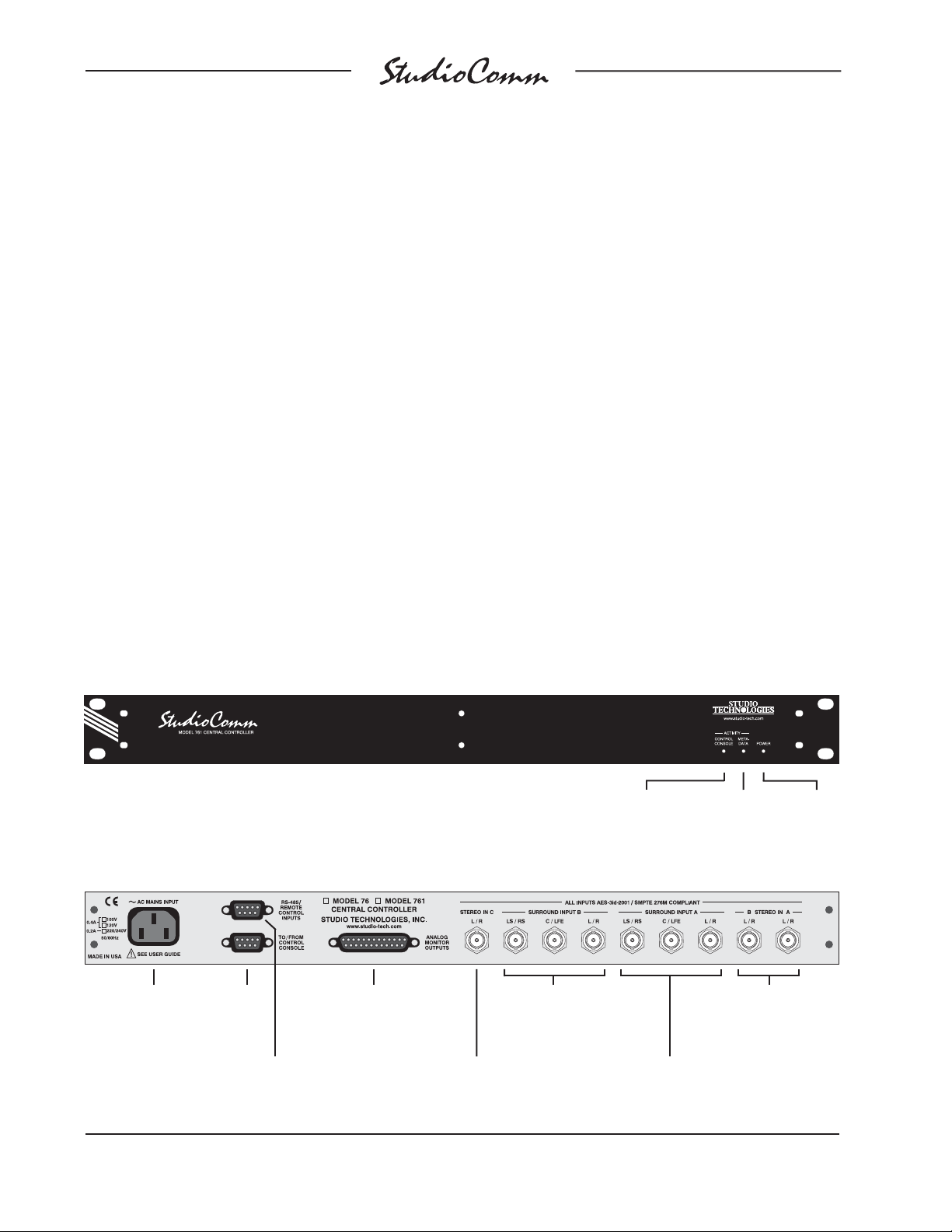
Figure 1. Model 761 Central Controller Front Panel
Figure 2. Model 761 Central Controller Back Panel
AC mains
input connection
To/from
Model 771
Control
Console
RS-485 and
remote control
inputs
Analog monitor
output connections
Stereo Input C
connection
Surround Input B
connections
Control console
to/from data
active LED
Surround Input A
connections
Metadata
active
LED
Stereo Input A and
Stereo Input B
connections
Powe r
present
LED
Issue 1, March 2008 Model 761/771 User Guide
Page 6 Studio Technologies, Inc.
Page 7
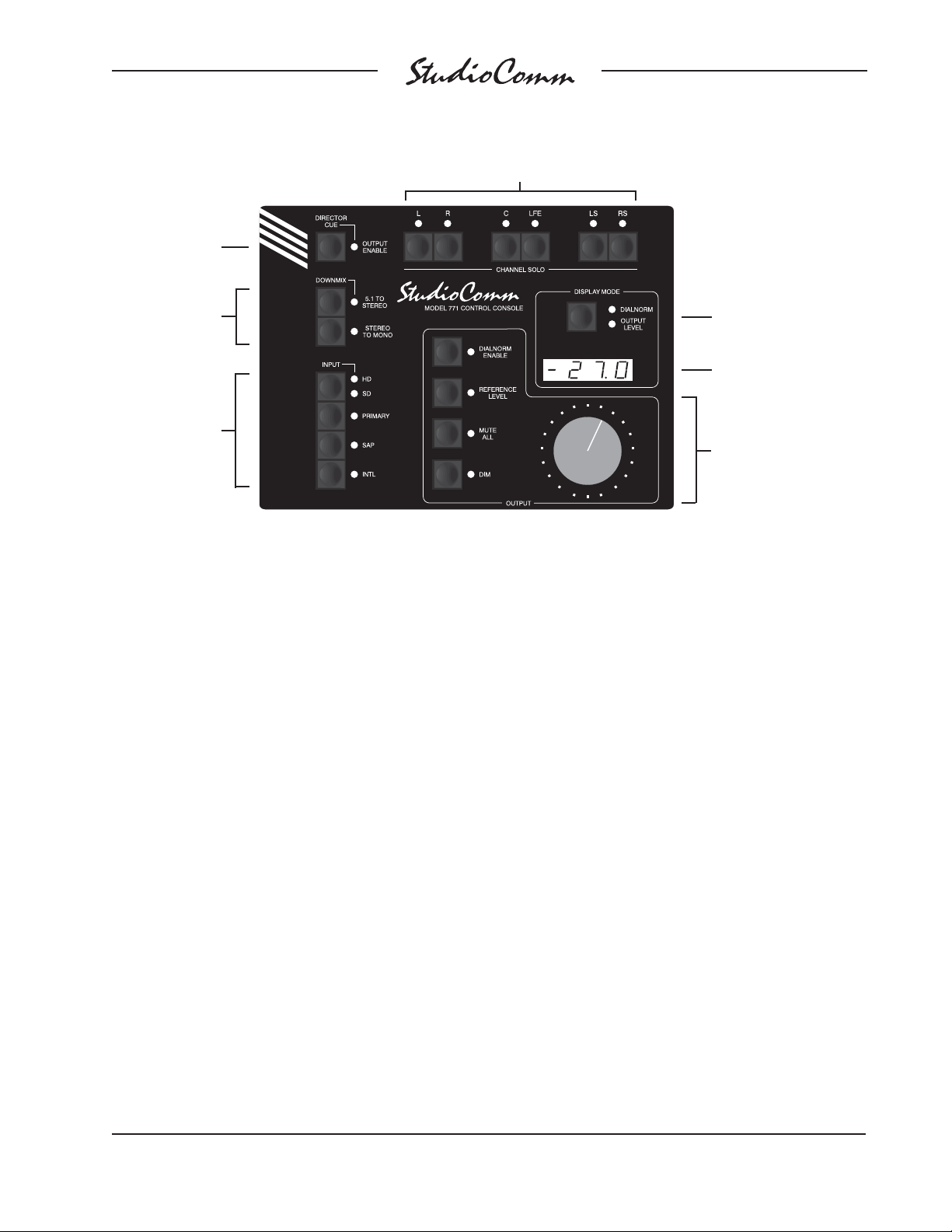
Director cue
output enable
for Surround
Channel solo
Downmix
Input select
Figure 3. Model 771 Control Console Front Panel
The 5.1 monitor output levels can be
controlled by way of a large, easy-to-use
rotary control. The level control auto
mute all function ensures the monitor
output channels automatically mute whenever the rotary level control is in its fully
counterclockwise (minimum) position.
By using the reference level function,
the monitor output level can be set to a
pre-confi gured value. This is provided
for audio-with-picture applications which
require a specifi c monitor level. The reference level is easily confi gured by taking an
electronic “snapshot” of the position of the
rotary level control. For operator confi rmation, a 4-digit LED display shows the level
of the monitor output. The display can be
confi gured for either an attenuation mode
or a direct db SPL value.
The dim function allows the monitor output
level to be reduced by a fi xed dB amount.
The dim level is selected from four available levels. A mute all function allows all
Display mode
Dialnorm and
monitor output
level display
Monitor Output
• Dialnorm enable
• Reference level
• Mute all
• Dim
• Rotary level control
monitor output channels to be simultaneously muted. The channel solo function
allows one or more specifi c channels to
be monitored while the others are automatically muted.
Two functions allow the format of the
monitored sources to be checked for level
or phase inconsistencies. The 5.1 to stereo downmix function is used to create a
stereo signal from the selected 5.1 surround source. The stereo to mono downmix function allows audio on the left and
right channels to be added (summed) and
monitored on the monitor’s system’s center
channel. The two downmix functions can
be simultaneously enabled, allowing a 5.1
surround source to be checked for mono
compatibility.
A special “director cue” output function
is provided. This allows a monaural or
stereo input to be connected to the Model
761 Central Controller, which also has
Model 761/771 User Guide Issue 1, March 2008
Studio Technologies, Inc. Page 7
Page 8

for Surround
a dedicated 2-channel stereo output associated with it. A button on the Model
771 Control Console allows on/off control
of this signal. This is useful when control
rooms need to monitor auxiliary audio
signals, such as site-event cue signals,
through an independent set of loudspeakers. For additional fl exibility, two remote
control input functions are provided: mute
all and dim. By providing access to these
functions, talkback or communications
activity from an audio console or matrix
intercom system can control the level of
the system’s 5.1 monitor outputs.
The Model 771 Control Console connects
to, and is powered by, the Model 761 Central Controller. The interconnecting cable
uses 9-pin D-subminiature connectors and
carries RS-485 data and DC power. The
Dolby E-compatible metadata connects to
the Model 761 by way of a second 9-pin
D-sub connector. Remote control signals,
including mute all and dim, also connect
to the Model 771 using the second 9-pin
D-sub connector.
Issue 1, March 2008 Model 761/771 User Guide
Page 8 Studio Technologies, Inc.
Page 9

for Surround
Installation
In this section you will be installing the
Model 761 Central Controller in an equipment rack. Connections to the digital audio
inputs and analog monitor outputs will be
made. A location will be selected for the
Model 771 Control Console and it will be
connected to the Model 761. If applicable,
a source of Dolby E metadata may be connected. In addition, external equipment will
be interfaced to the remote control inputs.
AC mains power will be connected to the
Model 761.
System Components
The shipping carton contains one each
of the following: Model 761 Central Controller, Model 771 Control Console, 20-foot
(6.1 m) 9-pin D-sub interconnecting cable,
and user guide. Units destined for North
America also include an AC mains cord.
Your dealer or distributor should provide an
AC mains cord for destinations outside of
North American.
Mounting the Model 761
The Model 761 Central Controller requires
one space in a standard 19-inch (48.3 cm)
equipment rack. Select a location that is
convenient for making connections to the
digital and analog audio signals as well
as to the Model 771 Control Console. A
20-foot (6.1 m) cable is supplied to connect the Model 761 to the Model 771. If the
needs of a specifi c installation dictate, an
alternate-length interconnecting cable can
be fabricated and used. Secure the Model
761 into the equipment rack using two
mounting screws per side.
Audio Connections
Audio signal connections are made by
way of multiple BNC jacks and a 25-pin
D-subminiature connector which are
located on the Model 761’s back panel.
Refer to Figure 2 for a detailed view of the
back panel. The BNC jacks will be used
for the digital audio signals. A cable assembly with a 25-pin D-sub plug (male) on
one end and the desired connectors on the
other end will be used for connecting to the
analog monitor outputs.
Digital Audio Inputs
The nine female BNC connectors on the
Model 761’s back panel are used to interface with digital audio signal sources.
Please refer to Figure 4 for details on the
supported inputs and the exact connectors
to be used.
Note that the input source titles in Figure 4
refer to the button selections on the Model
771 Control Console. It includes support
for three input sources each for both SD
(standard-defi nition) and HD (high-defi nition) programming. For SD the primary
source is either 5.1 surround or 2-channel
stereo while for HD the primary source
is intended to be 5.1 surround. In both
SD and HD the SAP (secondary audio
program) and INTL (international) inputs
are monaural. Of course, technically, all
the digital audio inputs on the Model 761
provide the same excellent audio quality.
The titles refer only to the intended signal
sources.
Each of the available digital audio inputs
is intended for connection to an unbalanced digital audio source that is compatible with the AES3id-2001 standard. In
broadcast environments these signals may
also be referred to as following the SMPTE
Model 761/771 User Guide Issue 1, March 2008
Studio Technologies, Inc. Page 9
Page 10
for Surround
SD–Primary
This input selection allows a 5.1 surround or 2-channel stereo audio source to be monitored.
Left Source: Channel 1, Surround A L/R input
Right Source: Channel 2, Surround A L/R input
Center Source: Channel 1, Surround A C/LFE input
LFE Source: Channel 2, Surround A C/LFE input
LS Source: Channel 1, Surround A LS/RS input
RS Source: Channel 2, Surround A LS/RS input
SD–SAP
This input selection allows a mono audio source to be monitored.
Source: Channel 1, Stereo A L/R input
SD–INTL
This input selection allows a mono audio source to be monitored.
Source: Channel 2, Stereo A L/R input
HD–Primary
This input selection allows a 5.1 surround audio source to be monitored.
Left Source: Channel 1, Surround B L/R input
Right Source: Channel 2, Surround B L/R input
Center Source: Channel 1, Surround B C/LFE input
LFE Source: Channel 2, Surround B C/LFE input
LS Source: Channel 1, Surround B LS/RS input
RS Source: Channel 2, Surround B LS/RS input
HD–SAP
This input selection allows a mono audio source to be monitored.
Source: Channel 1, Stereo B L/R input
HD–INTL
This input selection allows a mono audio source to be monitored.
Source: Channel 2, Stereo B L/R input
Director Cue
This input selection allows a 2-channel stereo audio source to be monitored using separate analog outputs.
L Source: Channel 1, Stereo C L/R input
R Source: Channel 2, Stereo C L/R input
Figure 4. Model 761 Digital Audio Inputs
Issue 1, March 2008 Model 761/771 User Guide
Page 10 Studio Technologies, Inc.
Page 11

for Surround
276M standard. As expected, these signal
sources will be provided in the form of
coaxial cables with BNC plugs attached.
The Model 761 supports sampling rates
of up to 192 kHz with a word length (bit
depth) of up to 24. Note that no external
synchronization source is required as the
inputs are all self-clocking.
Balanced AES3 digital audio signals can
also be used with the Model 761’s inputs
so long as external coupling transformers
(“baluns”) are utilized. These impedancematching (110 ohms to 75 ohms) transformer assemblies typically use a 3-pin
female XLR connector on their input and
a female BNC connector on their output.
Monitor Outputs
The connector labeled Analog Monitor
Outputs provides access to the Model
761’s 5.1 surround and 2-channel stereo
director cue monitor outputs. The surround
output channels are intended to connect
to the main surround loudspeaker system
incorporated in a facility. The director
cue output channels are provided to
support a separate set of loudspeakers,
allowing monitoring of inter- or intra-facility
communications.
The monitor output channels are intended
for connection to audio amplifi ers associated with monitor loudspeakers, or to the
inputs of loudspeakers that contain integrated amplifi ers. The monitor outputs are
electronically balanced and capable of
driving balanced or unbalanced loads of
600 ohms or greater. While balanced operation is preferred, unbalanced operation
does not pose a problem. To connect to
an unbalanced load connect the + terminal
as signal high, and both the – and shield
as the signal low/shield. For optimal unbalanced operation, it is important to connect
both – and shield together directly on the
D-sub plug, not at the other end of the
harness.
Note that while the Model 761’s electronically balanced output circuits are capable
of driving loads of 600 ohms or greater,
the output level will drop slightly as the
load impedance approaches 600 ohms.
A 0.5 dB difference in output level can be
expected as the load impedance changes
from 10 k ohms to 600 ohms.
The wiring scheme used by the D-subminiature connector complies with that
made popular by TASCAM® with their
DA-88® product. A wiring assembly prepared for the Model 761’s monitor outputs
is identical to that of a DA-88-style output
assembly. Please refer to Figure 5 for the
exact connection details. Note that unlike
a DA-88-style assembly, the Model 761’s
D-sub connector uses 4-40 threads. This
complies with the original design standard
for D-subminiature connectors.
Signal Signal
Connections High (+) Low (–) Shield
L 24 12 25
R 10 23 11
C 21 9 22
LFE 7 20 8
LS 18 6 19
RS 4 17 5
Director Cue L 15 3 16
Director Cue R 1 14 2
Notes: 1) Connector type on Model 761 is 25-pin D-subminiature
female. Installer must provide plug (male). Connector uses
4-40 threaded inserts for locking with mating plug.
2) Wiring scheme follows TASCAM DA-88 convention.
Standard DA-88-type wiring harnesses are directly
compatible, with the exception of 4-40 screw threads
being required.
Figure 5. Connections for Monitor and Director
Cue Outputs
Model 761/771 User Guide Issue 1, March 2008
Studio Technologies, Inc. Page 11
Page 12

for Surround
Metadata Input
The Model 761 allows a source of Dolby E
metadata to be directly connected. Hardware and software inside the Model 761
extracts (“parses”) a dialnorm data element from the connected metadata signal.
This dialnorm value can then be viewed
on the Model 771 and, if desired, used to
control the monitor output levels. Refer to
the Technical Notes section of this guide
for details.
The metadata must be in the form of an
RS-485 or RS-422 asynchronous serial
signal. This differential signal must have
a data rate of 115.2 kbit/s and a data format of 8 data bits, no parity, and 1 stop
bit (8-N-1). A metadata signal of this type
is commonly available on metadatagenerating or de-embedding equipment
from broadcast equipment manufacturers
such as Dolby Laboratories, Evertz, and
NVISION.
While technically the Model 761’s RS-485
connection is bi-directional, in software
it’s confi gured to only receive data. This
means that there’s no reason why a signal
already connected between two pieces of
equipment can’t be connected in parallel
(“bridged”) with the Model 761’s metadata
input. Refer to Figure 6 for exact connection details. While only the data+ and data–
connections are absolutely necessary,
a shield connection can also be made.
Note that the connections for the metadata
signal are reminiscent of the SMPTE 207M
standard.
Note that Studio Technologies has found
documentation supplied with some metadata-generating equipment has incorrect
pin-out information. This resulted in much
head scratching and hair pulling. As such,
it may be valuable to use a logic analyzer
Signal Pin Direction
RS-485 Data+ 7 Input
RS-485 Data– 2 Input
Data Shield 1 Shield
Remote Mute All 5 Input
Remote Dim 6 Input
Remote Spare 1 8 Input
Remote Spare 2 9 Input
Remote Input Common 4 Common
Note: Connector type on Model 761 is 9-pin D-subminiature
female. Connector uses 4-40 threaded inserts for
locking with mating plug.
Figure 6. Connector Pin Out for Metadata Input
and Remote Control Inputs
or oscilloscope to confi rm that the metadata source is terminated as expected
prior to connecting it to the Model 761.
Remote Control Inputs
Support is provided for two remote control input functions: remote mute all and
remote dim. The inputs use logic gates,
“pulled up” to +5 V by way of resistors,
which are active whenever they are
brought to their logic low state. Inputs of
this type are commonly referred to as GPI
inputs. While the input circuitry is protected
from over-current and static (ESD) discharge, care should be taken to prevent
nasty signals from reaching them. The
inputs are active only when held in the low
state; they can’t be confi gured to change
state (“latch”) in response to a logic pulse.
A 9-pin female D-subminiature connector
is used to interface with the remote control
inputs. This connector, labeled RS-485/
Remote Control Inputs, is located on the
back panel of the Model 761. Refer to
Figure 6 for exact connection details. Note
that pin 4 (remote input common) connects
to the Model 761’s internal circuit com-
Issue 1, March 2008 Model 761/771 User Guide
Page 12 Studio Technologies, Inc.
Page 13
for Surround
mon connection as well as the Model 761’s
chassis and mains earth connection. The
two spare inputs are provided for future
special applications. As such, pins 8 and 9
should remain unconnected.
Connecting the Model 761
to the Model 771
A 9-pin female D-subminiature connector,
labeled To/From Control Console, is provided on the back panel of the Model 761
Central Controller. Another 9-pin D-sub
connector, labeled To/From Central Controller, is provided on the back panel of
the Model 771 Control Console. A cable
with 9-pin male D-sub connectors on each
end is used to interconnect the two units. A
20-foot (6.1-meter) cable is included in the
shipping carton of each system. This cable
implements all nine connector pins in a
one-to-one manner.
Should an interconnecting cable of a
different length be required there’s no
problem for one to be fabricated and used.
While it can be wired in a one-to-one fashion covering all nine pins, a minimum of
only four connections are required: data+,
data–, DC+, and DC–. The Model 761’s
connector pin-out scheme was designed
to allow creation of an interconnecting
cable which uses commonly available twopair audio cable. This cable, consisting of
two twisted pairs each with an individual
shield, is often sleek, fl exible, and available
in many colors. One pair and shield can
be used for the data connections and the
other pair and shield can be used for the
DC connections. This implementation has
the advantages of providing a shield for
the data path and a more robust common
connection (two conductors including the
shield) for the DC power circuit. Refer
to Figure 7 for details.
It’s hard to specify a maximum interconnecting cable length. The data connections
won’t be the limiting factor as the differential transmission scheme of an RS-485
interface makes an interconnection in
excess of 1000 feet (300+ meters) easily possible. The culprit is the DC current
supplied by the Model 761 to power the
Model 771. This nominal 12 volt DC, 100
milliamperes maximum signal is subject
to the resistive voltage losses associated
with the interconnecting cable. For correct
Model 771 performance the voltage supplied to the Model 771, when measured
directly at the Model 771’s 9-pin connector
and at full load, must be 9 volts minimum.
This requires that the voltage drop due to
the interconnecting cable be no more than
3 volts DC. Using Ohm’s law, it’s quite easy
to determine whether the selected cable
will support the desired interconnection
length. To calculate the voltage drop, multiply the total resistance (in ohms) of the
proposed cable by 0.01 (the square of the
maximum current). Remember to include
the resistance in both the DC– and DC+
wires.
Signal Pin Direction
Data+ 1 To/From Model 771
Data– 6 To/From Model 771
Data Shield 2 To/From Model 771
DC+ 4 To Model 771
DC– 9 To Model 771
DC Power Shield 5 To/From Model 771
Note: Connector type on Model 761 is 9-pin D-subminiature
female. Connector uses 4-40 threaded inserts for
locking with mating plug.
Figure 7. Connections between Model 761 and
Model 771
Model 761/771 User Guide Issue 1, March 2008
Studio Technologies, Inc. Page 13
Page 14

for Surround
AC Mains Power
The Model 761 is internally confi gured
to operate from nominal 100, 120, or
220/240 V, 50/60 Hz. Units shipped to
North America are factory selected for
120 V operation. Units bound for Japan
are generally selected for 100 V while our
friends “down under” and in Europe receive units set for 220/240 V. Before connecting the Model 761 to AC mains power,
check to be certain that it is confi gured to
match the local mains voltage. Look on the
back panel (adjacent to the power entry
connector) for the factory-confi gured voltage. Note that an incorrect confi guration
could prevent operation or cause damage to the unit. Should it be necessary to
change the unit’s operating voltage it must
be performed only at the factory, or by a
factory-authorized service technician.
As soon as AC mains power is applied,
the Model 761 Central Controller’s power
LED will light steadily. The two activity
LEDs may also light. The Model 771
Control Console will go through a powerup sequence, lighting each LED in succession. Using its 4-digit display, the Model
771 will momentarily display both its, and
the Model 761’s, software revisions.
The Model 761 uses an IEC-standard C14
connector to mate with the AC mains cord.
The AC mains cord should have a C13
socket. The wire colors should conform to
the internationally recognized CEE color
code and be wired accordingly:
Connection Wire Color
Neutral (N) Light Blue
Line (L) Brown
Protective Earth (E) Green/Yellow
Safety Warning: The Model 761 does
not contain an AC mains disconnect
switch. As such, the AC mains cord
plug serves as the disconnection device. Safety considerations require that
the plug and associated outlet be easily accessible to allow rapid disconnection of AC mains power should it prove
necessary.
Issue 1, March 2008 Model 761/771 User Guide
Page 14 Studio Technologies, Inc.
Page 15

for Surround
Confi guration
After the physical installation has been
completed it’s important that the system’s
confi guration options be carefully reviewed.
In most cases one or more of the operating
parameters will need to be revised to meet
the needs of a specifi c installation. Many
of the parameters will impact the signal
fl ow in to and out of the Model 761 Central
Controller. Other parameters affect how
the Model 771 Console will display status
conditions and respond to user commands.
Confi gurable Parameters
Many StudioComm functions can be confi gured to meet the exact needs of an installation. The Model 771 Control Console
is used to display and select the desired
system confi guration. Here’s an overview
of what can be confi gured:
• Digital Input Sample Rate
• Digital Input Reference Level
• Monitor Output Nominal Level
Entering and Exiting the Confi guration
Mode
A small button is located on the back of
the Model 771 Control Console, adjacent
to the 9-pin D-sub connector. Pressing and
holding this button for two seconds places
both the Model 761 and the Model 771
into the confi guration mode. The Model
761 will immediately mute the analog outputs as a protection measure. In the confi guration mode the Model 771’s array of
buttons and LEDs no longer perform their
normal functions, instead they allow you to
observe and change many of the operating
parameters. The dialnorm and output level
LEDs, associated with the display mode
section, will light alternately to indicate that
the confi guration mode is active.
To leave the confi guration mode and return
the Model 771 to normal operation once
again press and hold the confi gure button
for two seconds. Note that confi guration
changes are stored in nonvolatile memory
only after the confi guration mode has been
exited.
• SD Primary Input Type
• Director Cue Output Nominal Level
• Reference Level
• Overall Display Mode
• SPL Reference Level
• Dialnorm Reference Level
• Dim Level
• Remote Inputs
The confi guration diagrams, located at
the end of this section, give details on setting each parameter. An overview of each
confi gurable parameter is provided in the
following paragraphs.
Model 761/771 User Guide Issue 1, March 2008
Studio Technologies, Inc. Page 15
Our apologies to those of you who fi nd
the confi gure button a pain to use, but it’s
supposed to be that way! Seriously, the top
of the button is slightly recessed from the
back panel, making it harder to accidentally activate. We didn’t want normal operation to cease because someone pushed
the Model 771 into a “rats nest” of schedules, magazines, or burrito wrappers! But
a fi rm press with the fl eshy part of an index
fi nger should do the trick.
There is no problem frequently “tweaking” the Model 771’s operating parameters
to achieve the desired performance. The
confi guration data is stored in nonvolatile memory, which is rated for thousands
of read and write cycles and a retention
Page 16

for Surround
time in tens of years. Note that the actual
memory integrated circuit is located in the
Model 761 Central Controller, rather than
in the Model 771 Control Console.
Digital Input Sample Rate
The Model 761’s digital audio inputs are
compatible with signals that have sample
rates spanning the professional digital
audio range of 32 to 192 kHz. A confi guration setting allows the performance of the
digital audio receiver integrated circuits to
be optimized for three sample rate zones
within the overall range. The choices are
32 to 48 kHz, 88.2 to 96 kHz, and 176.4
to 192 kHz. Note that selecting the 88.2
to 96 kHz setting will also allow signals
with a sample rate of 32 to 48 kHz to be
received. But audio performance of those
lower-rate signals may be compromised by
clock rate confusion in the receiver circuitry. This situation also holds true for the
176.4 to 192 kHz setting which will allow
signals with sample rates all the way down
to 32 kHz to be received. But again the
audio performance of the lower-rate signals could suffer from clocking errors. Note
that the inputs are confi gured as a group;
no individual receivers can be confi gured
to a range different from the others. This is
generally not an issue as a single sample
rate is typically selected for each facility.
Digital Input Reference Level
Confi guring the digital input reference level
to match that of a specifi c installation is
an important step toward achieving optimal
audio performance. This ensures that the
Model 761’s digital audio receiver integrated circuits are set to match the digital
input source’s “0 VU” or average point.
The digital input reference level can be
selected from four choices: –20.0, –18.0,
–16.0, and –14.0 dBFS. SMPTE recommends a reference level of –20 dBFS,
a value which is also extensively used
in professional audio applications. The
recommended digital reference level for
PAL broadcast applications is –18 dBFS.
The other two levels were included because… well, we can’t remember why! But
it seemed like a good idea at the time. If
you end up using the –16.0 or –14.0 dBFS
levels please let us know why.
Monitor Output Nominal Level
The nominal level of the six monitor output
channels can be confi gured, as a group, to
match the requirements of an installation.
This setting defi nes the analog output level
when a digital input source, at its reference level, is connected and the monitor
output level control is at its maximum. The
choices are 0.0 dBu and +4.0 dBu. Most
applications will fi nd the +4.0 dBu setting
correct as it meets the dominant worldwide
audio standards. For broadcast applications that follow the PAL standards the
0.0 dBu setting may be appropriate.
While sometimes not fully understood,
using the term dBu is more in line with
contemporary audio applications than the
outdated dBm and the “semi-pro” dBV
references; dBu refers to audio levels
without regard to their load impedance,
typical of situations where an output has a
low source impedance and is connected to
a high-impedance input. An analog audio
signal with a level of +4 dBu has an RMS
level of 1.228 volts. A 0 dBu signal will
have an RMS level of 0.775 volts.
A fi nal review of the selected setting might
now be in order. The most common input
and output combination will have a digital
input reference level of –20 dBFS and a
monitor output nominal level of +4 dBu.
Issue 1, March 2008 Model 761/771 User Guide
Page 16 Studio Technologies, Inc.
Page 17

for Surround
For PAL broadcast applications a setting
of –18 dBFS for the digital input and 0 dBu
for the analog outputs would be typical.
SD Primary Input Type
The type of source connected to the digital
audio input connectors associated with the
SD primary input selection can be confi gured. The choices are 5.1 surround or
2-channel stereo. When selected for 5.1
surround six input channels are associated
with SD primary: L, R, C, LFE, LS, and
RS. Selecting 5.1 surround as the input
type also allows the 5.1 to stereo downmix
function to be enabled. When the input
type is selected for 2-channel stereo only
the L and R channels are active for SD
primary; C, LFE, LS, and RS are disabled.
In addition, the 5.1 to stereo downmix
function is disabled.
system allows a precise monitor output
level to be stored, and then enabled by
pressing the Model 771 button labeled
Reference Level. Setting the reference
level is very simple but care is required:
1. Set up a precision sound pressure
level (SPL) measuring device at the
desired listening location.
2. Place the StudioComm system in the
normal operating mode, not the confi guration mode. Be certain that the dim,
mute all, reference, dialnorm enable,
and downmix functions are not active.
The remote mute or remote dim functions must also not be active.
3. Use the Model 771 Control Console
to select the input source that contains
the desired reference signal source,
e.g., pink noise.
Director Cue Output Nominal Level
The nominal level of the director cue output can be confi gured from four available
settings: +4.0 dBu, 0.0 dBu, –6 dBu, and
–12.0 dBu. This range of settings is provided so that compatibility can be achieved
with a variety of connected devices. The
+4.0 dBu and 0.0 dBu settings are appropriate for device inputs that expect to
receive full line-level signals. Devices such
as amplifi ed speakers will often perform
better when receiving signals with a lower
nominal level. In the latter case the ability
to comfortably use a level potentiometer
may be greatly enhanced using the –6.0
dBu or, especially, the –12.0 dBu setting.
Reference Level
For audio-with-picture applications it’s
often benefi cial for monitoring to be done
in reference to a known loudspeaker level.
This is often referred to as “mixing to
85 dB” on the monitors. The StudioComm
4. Observing the SPL meter, adjust the
Model 771’s rotary level control until
the desired reference monitor system
level has been reached.
5. Being careful not to disturb the position
of the rotary level control, enter
the confi guration mode by pressing
and holding the confi guration button
located on the Model 771’s back panel.
6. Once the confi guration mode has been
entered, the monitor outputs will mute.
Press and hold the reference button;
the associated LED will begin to fl ash.
After fi ve seconds the LED will light
solidly to indicate that a “snapshot” of
the new reference level has been taken. The level display will then show the
value of the new reference level. The
value shown will always be a negative
number as it’s always a value less than
the maximum output level. The reference button can now be released.
Model 761/771 User Guide Issue 1, March 2008
Studio Technologies, Inc. Page 17
Page 18

for Surround
7. To complete the process the confi guration mode must be exited. This is performed by again pressing and holding
the confi gure button for two seconds.
The new reference level is now stored
in the Model 761’s nonvolatile memory.
Only by repeating the entire procedure
can the value be changed.
Once the confi guration mode has been
exited, the monitor outputs will again become active. Confi rm that the correct level
has been stored by pressing the reference
button. The SPL meter should display the
desired level. If not, repeat the calibration
procedure to achieve the goal.
You might wonder why you have to press
and hold the reference button for fi ve
seconds before the selected value is recognized. This is provided specifi cally so
that unauthorized users won’t accidentally
change the reference level while they experiment with the confi guration mode. Only
if you know the “secret” will you be able to
store a new value.
Overall Display Mode
The Model 771’s 4-digit numeric display
can be confi gured to display the output
level in either an attenuation mode or an
SPL mode. In the attenuation mode the
output level is shown as a reduction in
value relative to the maximum output level.
When the rotary level control is at its fully
clockwise position the maximum output
level is obtained and the display will show
0.0. As the rotary control moves in the
counterclockwise direction the display will
show negative values, reaching approximately –69.5 dB before the full mute function automatically mutes the outputs.
In the SPL mode the display can be
confi gured to allow the output level to
be presented to a user in terms of the
actual sound pressure level (SPL). Used
in conjunction with the SPL reference level
confi guration and the stored confi guration
level, SPL mode allows a user to see a visual representation of the SPL level that is
present in the listening environment. While
correct implementation of the SPL display
mode takes a little more care, it can offer
an enhanced experience for StudioComm
users.
SPL Reference Level
The SPL reference level confi guration
allows a specifi c SPL number to be associated with the stored reference level value.
In this way whenever the monitor output is
at the stored reference level, either through
activating the reference level function or
manually adjusting the rotary level control, the Model 771’s display will show the
confi gured SPL level. Whenever the monitor output is not at the reference value the
display will show the current value, in dB,
relative to the reference level. The SPL
reference level can be confi gured over a
range of 70.0 to 100.0 dB in one-dB steps.
In many applications a value of 85 would
be appropriate, refl ecting the widely used
audio-for-picture 85 dB monitoring reference level. (Typically this 85 dB is really
85 dBC, indicating that a C-weighting fi lter
has been applied to the measurement.)
Other common reference SPL values,
such as 82 and 87, are well within the
allowable range.
Dialnorm Reference Level
The dialnorm reference level parameter is
provided so that the StudioComm system
can be confi gured to match a facilities’ or
Issue 1, March 2008 Model 761/771 User Guide
Page 18 Studio Technologies, Inc.
Page 19

for Surround
“plant” default dialnorm level. This value is
used as a reference against which the surround monitor output level will, if enabled,
be adjusted up or down in response to an
incoming dialnorm value. The dialnorm
reference level parameter can be adjusted
over the entire –31 to –1 dB range but
typical values will be in the range of –27 to
–24. Implementation purists might want to
select –31 dB as it may well be the “truest”
implementation of the dialnorm scheme.
In this way the system will, when enabled,
reduce the monitor output level whenever
dialnorm is different than –31 dB. But as
bar fi ghts have broken out over decisions
such as this we’ll leave the choice up to
you! For additional information about dialnorm refer to the Technical Notes section
of this user guide.
Dim Level
Restore Factory Defaults
The restore factory defaults function is provided primarily for factory use. In this way
a system can be shipped with the default
settings selected. While you are welcome
to use this function, be careful that your
confi guration efforts aren’t wasted. Specifi cally, be aware that the reference level
is reset to minimum level. All the other
parameters are fairly easy to set up, but
resetting the reference level would require
getting out an SPL meter and connecting
a calibrated signal source. This is a hassle
you may not need!
The dim function is used to reduce the
monitor output level by a preset amount.
The reduction is in dB relative to the monitor output’s current level. There are four
dim level values available: –10.0, –15.0,
–20.0, and –25.0 dB.
Remote Mute All
Two confi guration choices are associated
with the remote mute all function: disabled
and enabled. To utilize the remote mute all
function simply requires you to select the
enabled setting.
Remote Dim
Two confi guration choices are associated
with the remote dim function: disabled and
enabled. To utilize the remote dim function
simply confi gure it for enabled.
Model 761/771 User Guide Issue 1, March 2008
Studio Technologies, Inc. Page 19
Page 20

for Surround
Model 771 Confi guration—Entering and Exiting
Confi guration Mode
Press and hold the confi guration
button for 2 seconds to enter or
exit the confi guration mode.
These LEDs will
light alternately
when confi guration
mode is active.
Issue 1, March 2008 Model 761/771 User Guide
Page 20 Studio Technologies, Inc.
Page 21

for Surround
Model 771 Confi guration—Digital Input Sample Rate, Digital
Input Reference Level, and Monitor Output Nominal Level
When the Mute All button is pressed, the 4-digit display shows
the currently selected digital input reference level. Use the 5.1
to Stereo button to increase the reference level. Use the Stereo
to Mono button to decrease the reference level. Available digital
input reference levels are –20.0 dBFS, –18.0 dBFS, –16.0 dBFS,
and –14.0 dBFS.
When the Mute All button is pressed, use the
Channel Solo L and R buttons to select the
monitor output nominal level. Use the buttons
to change the confi guration. LED L lit means
nominal level is 0.0 dBu; LED R lit means
nominal level is +4.0 dBu.
When the Mute All button is pressed, use
these buttons to select the digital input
sample rate. INTL lit means 32 to 48 kHz;
SAP lit means 88.2 to 96 kHz; Primary lit
means 176.4 to 192 kHz.
Default: 32 to 48 kHz digital input sample rate.
–20.0 dBFS digital input reference level.
+4.0 dBu monitor output nominal level.
Model 761/771 User Guide Issue 1, March 2008
Studio Technologies, Inc. Page 21
Press and hold the Mute All button
to display and select the digital input
sample rate, digital input reference level,
and monitor output nominal levels.
Page 22

for Surround
Model 771 Confi guration—SD Primary Input Type
Use the 5.1 to Stereo and Stereo to Mono buttons
to set the SD primary input type. 5.1 to Stereo LED
lit means SD primary is 5.1; Stereo to Mono LED lit
means SD primary is stereo.
Press and hold
the HD/SD and
Primary buttons
to display and
select the SD
primary input
type.
Default: Stereo SD primary input type.
Issue 1, March 2008 Model 761/771 User Guide
Page 22 Studio Technologies, Inc.
Page 23

for Surround
Model 771 Confi guration—Director Cue Output Nominal Level
Press and hold the Director Cue Output
Enable button to display and select the
director cue output nominal level.
When the Director Cue Output Enable button is pressed, the 4-digit
display shows the selected director cue output nominal level. Use the
5.1 to Stereo button to increase the nominal level. Use the Stereo to
Mono button to decrease the nominal level. Available director cue
output nominal levels are: +4.0 dBu, 0.0 dBu, –6.0 dBu, and –12.0 dBu.
Default: +4.0 dBu director cue output nominal level.
Model 761/771 User Guide Issue 1, March 2008
Studio Technologies, Inc. Page 23
Page 24

for Surround
Model 771 Confi guration—Reference Level
Press and hold the Reference Level button for 5 seconds to take a
“snapshot” of the level control’s setting at the time confi guration mode
was entered. The Reference Level LED will fl ash when the button is
initially pressed and then light solid when the “snapshot” has been taken.
Default: Reference level set for fully attenuated (minimum) monitor output level.
Note: The 5-second delay is a safety feature ensuring that the reference level will not be accidently changed.
To permanently store the new value, you must still exit the confi guration mode.
Issue 1, March 2008 Model 761/771 User Guide
Page 24 Studio Technologies, Inc.
Page 25

for Surround
Model 771 Confi guration—Overall Display Mode and
Reference Level in dB SPL
When the Display Mode button is pressed, use the
Channel Solo L and R buttons to select the overall
display mode. LED L lit means attenuation mode is
selected; LED R lit means SPL mode is selected.
Use the buttons to change the confi guration.
When the Display
Mode button is
pressed, use the
5.1 to Stereo button to increase the
reference level in
dB SPL. Use the
Stereo to Mono
button to decrease
the reference level.
The range is 70.0 to
100.0 dB in one-dB
steps.
Press and hold
the Display Mode
button to display
and set the overall
display mode and
the SPL reference
level.
Default: Attenuation display mode selected.
85.0 dB SPL reference level.
Model 761/771 User Guide Issue 1, March 2008
Studio Technologies, Inc. Page 25
Page 26

for Surround
Model 771 Confi guration—Dialnorm Reference Level
When the Dialnorm
Enable button is
pressed, use the 5.1
to Stereo button to
increase the dialnorm
reference level. Use
the Stereo to Mono
button to decrease
the dialnorm reference level. The range
is –31 to –1 dB in
one-dB steps.
Press and hold the Dialnorm
Enable button to display and set
the dialnorm reference level.
Default: –31 dB dialnorm reference level.
Issue 1, March 2008 Model 761/771 User Guide
Page 26 Studio Technologies, Inc.
Page 27

for Surround
Model 771 Confi guration—Dim Level, Remote Mute All, and
Remote Dim
This LED displays the confi guration
of remote mute all. LED not lit means
remote mute all is disabled; LED lit
means enabled. Use the button to
change the confi guration.
This LED displays the confi guration
of remote dim. LED not lit means
remote dim is disabled; LED lit
means enabled. Use the button to
change the confi guration.
When the Dim button is pressed, the 4-digit
display shows the currently selected dim level.
Use the 5.1 to Stereo button to decrease the
dim level. Use the Stereo to Mono button to
increase the dim level. Available dim levels are
–10.0 dB, –15.0 dB, –20.0 dB, and –25.0 dB.
Default: –20.0 dB dim level.
Remote mute all disabled.
Remote dim disabled.
Model 761/771 User Guide Issue 1, March 2008
Studio Technologies, Inc. Page 27
Press and hold the Dim button to display
and select the dim level, remote mute all,
and remote dim input confi gurations.
Page 28

for Surround
Model 771 Confi guration—Restore Factory Defaults
Press and hold both the Dialnorm Enable and Dim buttons for 5 seconds
to restore Model 771 factory defaults. Once defaults have been restored,
the associated LEDs will light. After the buttons are released, confi guration mode will be exited and normal operation will resume.
Factory Defaults: 32 to 48 kHz digital input sample rate.
–20.0 dBFS digital input reference level.
+4.0 dBu monitor output nominal level.
Stereo SD primary input type.
+4.0 dBu director cue output nominal level.
Reference level set for fully attenuated (minimum) monitor output level.
Attenuation display mode selected.
85.0 dB SPL reference level.
–31 dB dialnorm reference level.
–20.0 dB dim level.
Remote mute all disabled.
Remote dim disabled.
Note: The 5-second delay is a safety feature ensuring that the factory defaults will not be accidently
restored.
Issue 1, March 2008 Model 761/771 User Guide
Page 28 Studio Technologies, Inc.
Page 29

for Surround
Operation
Now that you’ve installed and confi gured
the system, you’re ready to go. You should
fi nd operation very easy. However, taking
time to study this section of the guide may
prove valuable, especially regarding the
system’s support for dialnorm.
Model 761 Central Controller
The Model 761’s front panel contains
three LEDs. The power LED should be lit
whenever AC mains power is connected.
The control console activity LED will light
steadily whenever the Model 761 is communicating correctly with the Model 771.
This LED will remain off during the system
power-up process, something that typically
takes several seconds to complete. The
metadata activity LED will light whenever
an active metadata signal has been connected and valid sync word information is
being received.
Model 771 Control Console
StudioComm operation is controlled using
the Model 771 Control Console and, if connected, the remote control inputs. To make
things easy to describe, we’ve divided the
StudioComm functions into seven main
groups: input source selection, downmix,
monitor output general functions, channel
solo, director cue output, display and display mode, and remote control inputs.
Input Source Selection
Four input select buttons work together to
allow monitoring of up to six input sources.
One source can be selected for monitoring at any one time. The input sources are
grouped into two sets of three with the
groups labeled SD and HD. Each group’s
three input sources are labeled primary,
SAP, and international (INTL). The titles
were selected to match the names commonly assigned to sources in broadcast
facilities. The SD (standard defi nition)
primary input supports either a 5.1 surround or 2-channel stereo source. The HD
(high defi nition) primary input supports a
5.1 surround source. The SD and HD SAP
and international inputs each support a
single-channel monaural source. SAP is a
broadcast-derived acronym for secondary
audio program. An “international” source
simply refers to an alternate source that
is typically associated with remotely originated broadcast material. Note that, as
would be expected, the titles of the actual
sources connected to a specifi c StudioComm system may not match the Model
771’s descriptions. Local technical personnel should be familiar with the actual connected sources.
The SD/HD button is used to select the
active group. Pressing the button will
alternate between the groups. Two LEDs
are associated with the SD/HD button
and indicate which of the groups is active.
Three buttons are used to select the specifi c input source to be monitored. They
are labeled primary, SAP, and INTL (international). LEDs are associated with these
buttons and indicate which is active. Note
that the Model 771 “remembers” which
specifi c input was last selected for each
group, so changing between groups will
switch between two specifi c inputs. This
allows rapid switching between, as
an example, SD primary and HD SAP.
Downmix
Two downmix functions allow users to perform “real-world” audio format compatibility
checks. One function allows a 5.1 surround
signal to be “folded down” (converted) to
Model 761/771 User Guide Issue 1, March 2008
Studio Technologies, Inc. Page 29
Page 30

for Surround
stereo. The other allows a stereo signal to
be converted to mono. Using the downmix functions simply requires pressing the
designated buttons. The buttons are set to
“latch” the functions on and off. An LED is
located adjacent to each button and lights
whenever its respective function is active.
When the 5.1 to stereo downmix function is enabled the LS and RS channel’s
associated with a 5.1 surround signal is
combined (“folded down”) with the L and
R signals to create a 2-channel stereo
(left and right) signal. The resulting stereo
signal is routed to the left and right monitor output channels. The LS, RS, and LFE
monitor output channels are muted. By utilizing this downmix function phase relationships and inter-channel level issues can be
quickly observed.
The stereo to monaural downmix function
combines the left and right audio channels
to create a single-channel monaural signal.
This signal is sent to the center channel
monitor output. The L, R, LS, RS, and LFE
channels are muted. Please refer to the
Technical Notes section of the guide for a
detailed description on how the downmix
functions perform their tasks.
Note that when a 5.1 surround source is
selected as the input source, the 5.1 to
stereo downmix function will automatically enable whenever the stereo to mono
downmix function is enabled. This ensures
that an operator will hear a mono signal
created by folding down all channels associated with the selected input.
The Model 771 associates the state of
the downmix functions with the currently
selected input. For example, if HD primary
is the selected input source and 5.1 to
stereo downmix is enabled, that condition
will be “remembered” when switching to
another input source. Upon returning to
HD primary as the input source, the 5.1 to
stereo downmix function will again become
active.
Note that a specifi c downmix function can
only be enabled when it is applicable for
the currently selected input source. This
means that the 5.1 to stereo downmix
function can only be enabled when a 5.1
surround input source is selected. Neither
of the downmix functions can be enabled
when one of the SAP or international input
sources is selected. This is because these
inputs are already monaural and wouldn’t
be subject to any additional fold down.
Monitor Output General
Functions
Four buttons and one rotary control are
associated with the monitor output functions. The buttons control operation of the
dim, mute all, reference level, and dialnorm
enable functions. The rotary level control
is used to manually set the monitor output
level.
Dim
The dim function is provided for user
convenience, allowing the monitor output
level to be reduced by a fi xed amount. The
Model 771’s confi guration mode allows the
dim level to be selected from among four
choices: –10, –15, –20, or –25 dB. Pressing the dim button will enable the function.
The dim button is always set to “latch” the
function on and off. The 4-digit display,
when selected for output level mode, will
indicate the revised monitor output level.
If the “dimmed” output level is equal to or
less than the minimum attenuated level,
the monitor output will go into a full mute
and the display will show four horizontal
dashes. When dim is active the monitor
Issue 1, March 2008 Model 761/771 User Guide
Page 30 Studio Technologies, Inc.
Page 31

for Surround
output level reduction will apply no matter
whether the monitor output level is being
set by the rotary level control or by the
reference level button. The LED associated
with the dim button will light whenever dim
is active. If dim mode is enabled via the
remote dim function the dim LED will fl ash.
It’s worth a using a few sentences to discuss the auto dim off function. Whenever
dim is enabled due to the dim button being
pressed, as well as the rotary level control
being active (reference level mode is not
active), changing the setting of the rotary
level control will automatically turn off dim.
The auto dim off function is a unique attempt at protecting the aural health of
users. No longer will there be a heartstopping blast of audio when the dim button is pressed, supposedly to enable dim,
but actually turning dim off because it was
already enabled. It’s hard to explain unless
you’ve experienced this in person—trust
us, this situation can and does happen!
Note that the auto dim off function is not
active whenever dim is enabled due to
the remote dim function being active. This
allows remote control equipment, such
as a talkback system, to reliably dim the
monitor outputs.
Mute All
The mute all function is highly complicated
to operate—not! Pressing the mute all button causes all six monitor output channels
to mute. The 4-digit display indicates the
mute condition by showing four horizontal
dashes. The mute all button is always set
to “latch” the function on and off. The LED
associated with mute all will light whenever
mute all is active. Note that if mute all is
enabled via the remote mute all function,
the mute all LED will fl ash.
Reference Level
The reference level button sets the monitor output level to a preset value. Technical
personnel, using a sound-pressure-level
(SPL) meter and precision signal source,
should have set this level to meet the
requirements of the exact monitoring
environment. The LED associated with the
reference level button lights whenever the
function is active. Whenever the reference
level mode is active the rotary level control
is disabled. The 4-digit display will indicate
the reference output level. Note that the
system’s default reference level is full mute
so “out of the box” the 771 will display four
horizontal lines when reference level mode
is enabled.
The reference level LED also serves as a
calibration aid. If the reference level mode
is not active, whenever the monitor output
level is precisely the same as that stored
for the reference value the reference LED
will fl ash. The monitor output level can
reach this exact level through the use of
the rotary level control by itself or through
the setting of the rotary level control in
conjunction with the dialnorm data and dim
function. Whatever path the output level
takes to reach the reference level value, it
will cause the reference level LED to fl ash!
Dialnorm Enable
Enabling the dialnorm level function simply requires pressing the dialnorm enable
button. The button provides a “latching”
function so that the selected state is maintained. An associated LED will light whenever the function is active. The dialnorm
enable function is only active when the
input source is selected for HD primary.
(This is because dialnorm level data is
available only for that specifi c source.)
Model 761/771 User Guide Issue 1, March 2008
Studio Technologies, Inc. Page 31
Page 32

for Surround
When enabled, and HD primary is the input
source, as the dialnorm level changes the
output level will automatically increase or
decrease as is appropriate. During confi guration of the system a dialnorm reference
level was entered. This level, typically in
the range of –27 to –24 dB, is compared to
the incoming dialnorm level value. If the received dialnorm level is less than the reference value the output level is increased by
the difference. If the received dialnorm level
is greater than the reference value the output level is decreased, again by the difference. Note that dialnorm levels are limited
to a range of –31 to –1 dB. This restricts the
maximum amount of level control to 30 dB.
The 4-digit display, when selected for output level mode, will display all level changes
as they occur, including level changes due
to dialnorm activity. The received dialnorm
level values can themselves be viewed by
selecting the display dialnorm mode.
In either display mode the decimal point
“dot” in the lower-right corner of the display
will light whenever the input dialnorm value
matches the dialnorm reference value. This
topic is described in greater detail in the
Display and Display Mode section of this
section of this guide. The Technical Notes
section of this guide also will provide additional useful information about dialnorm.
Rotary Level Control
The rotary level control is used to manually
adjust the monitor output level. It is active
whenever the reference level function is not
active. The level control provides the ability
to adjust the monitor output level over an
approximately 70 dB range. The reference
LED will fl ash when the rotary level control
sets the output level to be the same as the
stored reference level. Whenever the rotary
level control is set to its fully counterclockwise position, the monitor output channels
automatically mute. Technically, this has
the same effect as when the mute all function is active.
Channel Solo
The channel solo function allows specifi c
channels to be selected for individual or
group “solo” monitoring. The function takes
place electrically “after” the input source
selection, downmix, and level control functions. A channel selected for solo actually doesn’t change, but the solo function
causes the non-soloed monitor output
channels to mute. This leaves only the
soloed output active. Six buttons and six
LED indicators are associated with the
channel solo function. To solo a channel
simply requires pressing one of the solo
buttons. The buttons function in a pressto-enable/press-to-disable “latching” mode.
The LED associated with a soloed channel will fl ash to indicate that solo is active.
More than one output channel can be selected for soloing at a time. The Model 771
even allows all six monitor output channels
to be simultaneously selected for solo. This
seems like an “all soloed so none soloed”
mode but this condition is specifi cally
allowed so that an output channel mute
function can be provided. By fi rst soloing
all output channels an operator can then
“un-solo” specifi c channels, directly muting
them. It’s a bit confusing to describe
in words but is very simple to use and
can be very useful resource—try it out
and you’ll see!
Director Cue
Controlling the on/off state of the director
cue output is simply a matter of pressing
the director cue button. It functions in an
Issue 1, March 2008 Model 761/771 User Guide
Page 32 Studio Technologies, Inc.
Page 33

for Surround
alternate action manner to change the
current state of the output. An associated LED lights whenever the director cue
output is active. The director cue output is
not impacted, nor does it impact any of the
other Model 771 functions.
Display and Display Mode
The 4-digit LED display can be selected
to show either the output level or the
dialnorm level. The display mode button
is used to select the desired mode. Two
LEDs are associated with the button, indicating which mode is active. When selected for the output level display mode, what
the digits actually show will depend on how
the Model 771 is confi gured. If confi gured
for the attenuation mode the display will
show the output level as an attenuation
value in reference to the maximum output.
For example, when the rotary level control
is set to its fully clockwise position the displays will typically show 0.0. This indicates
that no attenuation is taking place in the
signal path. (The signal path starts with the
selected input source and ends with the
monitor outputs.) As the rotary level control
is moved counterclockwise readings such
as –20.0 or –35.0 would be typical.
If the Model 771 is confi gured to display
the output level in SPL, the 4-digit display
will always show the output level in positive
numbers. These numbers are intended to
represent the sound pressure level in dB
SPL, a fi gure that should directly relate to
the actual sound pressure level that the
loudspeaker system is presenting to users.
(Typically, the level value would actually
be in dBC, the C-weighted sound pressure
level.) When the reference level button is
enabled, or the rotary level control is set so
that the reference level has been reached,
the display will typically show something in
the range of 82 to 87. Assuming that
the monitoring environment has been
correctly calibrated, this would indicate
that an average listening level of 85 dB
SPL, for example, had been achieved.
When the 4-digit display is set for the dialnorm display mode a much different piece
of information will be shown to the user. It
will show the somewhat obscure but important dialnorm level parameter that’s associated with the HD primary input source.
As has been covered in other parts of this
guide, dialnorm is intended to provide a
numeric value that represents the average dialog level associated with an audiofor-picture element. Technically, dialnorm
values can range from –31 to –1 dB but
during actual operation they will typically
be in the range of –30 to –20 dB. The value
may change frequently in conjunction
with changes to the actual audio signal. In
other situations the dialnorm level will only
change when certain sources, such as a
live 5.1 surround event, are being “aired.”
On the extreme end, in some facilities
the dialnorm level is fi xed and won’t ever
change. That’s not really in the spirit of
what dialnorm is supposed to accomplish,
but c’est la vie. Whatever the dialnorm
level—the Model 771 will display it!
In both display modes a special feature is
provided to assist users in knowing if the
current dialnorm level matches a facility’s
“house” reference. This reference level,
typically in the range of –24 to –27 dB,
is entered as part of the Model 771’s
confi guration process. The “dot” in the
lower-right corner of the 4-digit display will
light whenever the incoming dialnorm level
matches the stored reference level. Refer
to Figure 8. This feature can be useful in
broadcast transmission and distribution
applications. In theory, any time the
Model 761/771 User Guide Issue 1, March 2008
Studio Technologies, Inc. Page 33
Page 34

for Surround
Figure 8. Incoming dialnorm level match “dot”
dot in the lower-right corner is not lit the
current dialnorm level value is causing a
level adjustment to take place. This level
adjustment can be taking place in the
StudioComm system, if the dialnorm
enable function is active, as well as in
downstream users of the broadcast signal.
When an external signal activates remote
dim the LED on the Model 771 associated with the dim function will fl ash. If dim
was already active when remote dim is
activated, the LED will change from being
steadily lit to fl ashing.
Note that if a valid dialnorm source is not
available the 4-digit display, when selected
to display dialnorm, will show four horizontal bars. This could be due to a problem
with the metadata signal connected to the
Model 761 Central Controller. But more frequently this will simply be the normal result
that occurs when the Model 771’s input is
not selected for HD primary.
Remote Control Inputs
Two remote control signals can be connected to the StudioComm system and
confi gured for operation. The two functions are remote mute all and remote dim.
When an external signal activates remote
mute all the LED on the Model 771 associated with mute all will fl ash. If mute all was
already active when the remote mute all
function is activated, the LED will change
from being steadily lit to fl ashing.
Issue 1, March 2008 Model 761/771 User Guide
Page 34 Studio Technologies, Inc.
Page 35

for Surround
Technical Notes
Dialnorm
A source of Dolby E metadata can be connected to the Model 761 Central Controller.
Within this fl ow of metadata frames will be
a “dialnorm” level value that’s associated
with the 5.1 surround signal that serves
as the Model 761’s HD primary input. The
dialnorm level value can be displayed by
the Model 771 Control Console and used
to control the monitor output level.
Technically, the metadata is in the form
of a 115.2 kbit/s RS-485/RS-422 signal
that contains a number of data elements,
including one or more that represent the
average dialog level (dialog normalization
or dialnorm) in the audio program signals
being carried over the digital audio portion of the related Dolby E interface. These
dialnorm levels are associated with specifi c programs within the 8-channel audio
“stream.” Firmware within the Model 761 is
able to parse (separate) the data elements,
specifi cally separating the fi rst dialnorm
level value in the metadata frame from the
one or more that may be present later. To
clarify, any dialnorm level elements that
occur later in the same metadata frame
are ignored. This method was selected as
it was assumed that the fi rst dialnorm level
element will always be associated with a
5.1 program. There’s a technical basis for
why this should be true. In Dolby E a 5.1
program is always assigned to the fi rst six
channels (channels 1-6). While there may
be separate dialnorm values associated
with audio channels 7 and 8, they are not
relevant for correct StudioComm system
operation.
Downmix
The downmix functions are implemented
in the Model 761 Central Controller’s
hardware using analog circuitry. The 5.1
to stereo downmix function performs this
action: center (C) dropped in level by 6 dB
and routed to left (L) and right (R) monitor
outputs; left surround (LS) dropped in level
by 3 dB and routed to L monitor output;
right surround (RS) dropped in level by
3 dB and routed to R monitor output; lowfrequency-enhancement (LFE) input muted. The stereo to mono downmix function
performs this action: L dropped in level by
3 dB and routed to the C monitor output;
R dropped in level by 3 dB and routed to
the C monitor output; C, LS, RS, and LFE
inputs mute.
“Hot” Disconnection of the
Model 771 Control Console
There’s no problem relocating the Model
771 Control Console while your StudioComm system is operating. You can disconnect the 9-pin interconnecting cable,
move the unit, and then re-connect without
issue. Upon disconnection the Model 761
Central Controller will mute the monitor output channels as well as saving the
current operating parameters. No clicks,
pops, or other noises will occur when the
Model 771 is again connected. The Model
771 will go through its standard power-up
sequence and then normal operation will
resume.
Monitor Output Transient
Protection
The Model 761 Central Controller contains
a power-up/power-down transient protection feature. This limits the chance of
Model 761/771 User Guide Issue 1, March 2008
Studio Technologies, Inc. Page 35
Page 36

for Surround
damage to the monitor loudspeakers
during the time when AC mains voltage is
connected, disconnected, or has changed
signifi cantly from nominal. A combination
of hardware and software is used to monitor one of the power supply “rails.” Until
the AC mains input exceeds its nominal
operating voltage range, electromechanical
relays maintain a short-circuit condition
on the monitor outputs. After the input voltage is recognized as valid, a short delay
takes place before the relays are allowed
to function normally. Whenever the AC
mains input drops below its nominal operating voltage range, the relays immediately
go to their mute state. During testing it
was found that upon power up the monitor
outputs remained very quiet; during power
down a small to moderate “tick” was the
worst that was heard.
Mono-to-Center Polarity
It’s worthwhile to note that a polarity inversion takes place whenever the stereo to
mono downmix function is active. By design, the left (L) and right (R) input signals
experience a 180-degree inversion in
the Model 761’s combining circuitry. This
should not cause a problem as monitoring
audio signals over a single loudspeaker is
considered polarity insensitive. Only during
electrical testing would this condition be
detected.
Model 761 to Model 771
Connections
Figure 7 gives a detailed description of
the signals that connect the Model 761
Central Controller to the Model 771
Control Console. The Model 761 provides
a +12 volt DC power source for use by the
Model 771’s circuitry. The DC output is
current-limited to minimize the chance that
a short-circuit condition will damage the
Model 761’s circuitry. An asynchronous,
bi-directional, data interface links the two
units. The RS-485 hardware connection
scheme operates at a rate of 115.2 kbit/s
and uses an 8-N-1 data format. The Model
761 communicates with the Model 771
20 times per second, receiving button and
rotary level control information and sending LED and 4-digit display status data.
Issue 1, March 2008 Model 761/771 User Guide
Page 36 Studio Technologies, Inc.
Page 37

for Surround
Specifi cations
Model 761 Central Controller
General Audio:
Frequency Response: digital inputs to monitor
outputs loaded with 10 k ohms
32 to 48 kHz Sample Rate: 20 Hz-20 kHz
±0.05 dB
88.2 to 96 kHz Sample Rate: 20 Hz-40 kHz
±0.05 dB
176.4 to 192 kHz Sample Rate: 20 Hz to 40 kHz
±0.05 dB; down 0.5 dB at 80 kHz
Distortion (THD+N): 0.004%, ref 1 kHz, +4 dBu
output
S/N Ratio: 86 dB, ref +4 dBu output
Dynamic Range: greater than 106 dB
Crosstalk: 104 dB at 1 kHz; 90 dB at 20 kHz,
ref –1 dBFS input
Digital Audio Inputs: 9
Confi guration: organized as two 5.1 surround, one
2-channel stereo, and two dual-channel monaural
Supported Sample Rates: 32, 44.1, 48, 88.2, 96,
176.4, and 192 kHz
Word Length: 24 bit
Type: AES3id-2001 (SMPTE 276M)
Impedance: 75 ohms, unbalanced
Reference Level: –20, –18, –16, or –14 dBFS,
selectable
Sync Source: all inputs independently self-clocking
Monitor Outputs: 8
Confi guration: organized as one 5.1 surround and
one 2-channel stereo
Type: electronically balanced, compatible with
balanced or unbalanced loads
Maximum Level: +26 dBu into 600 ohms or
greater
Nominal Level, Channels 1-6 (5.1 Surround):
0 or +4 dBu, selectable
Nominal Level, Channels 7 and 8 (Director Cue):
–12, –6, 0, or +4 dBu, selectable
Remote Control Inputs: 4
Function: remote mute all, remote dim, two spare
Type: +5 V logic, activates on closure to system
common
AC Mains Requirement: 100, 120, or 220/240 V,
±10%, factory confi gured, 50/60 Hz, 30 watts
maximum
Connectors:
Digital Audio Inputs: 9, 75 ohm BNC (per IEC
60169-8 Amendment 2)
Monitor Outputs: 25-pin D-subminiature female
Control Console: 9-pin D-subminiature female
Metadata and Remote Control Input: 9-pin
D-subminiature female
AC Mains: 3-blade, IEC 320 C14-compatible
(mates with IEC 320 C13)
Dimensions (Overall):
19.00 inches wide (48.3 cm)
1.72 inches high (4.4 cm)
8.75 inches deep (22.2 cm)
Mounting: one space in a standard 19-inch rack
Weight: 8.8 pounds (4.0 kg)
Model 771 Control Console
Application: supports Model 761 Central Controller
Power: +12 volts DC, 100 mA maximum, provided
by Model 761 Central Controller
Control Data:
Type: RS-485
Data Rate/Format: 115.2 kbit/s, 8-N-1
Connector: 9-pin D-subminiature female
Dimensions (Overall):
7.20 inches wide (18.3 cm)
2.20 inches high (5.6 cm)
5.40 inches deep (13.7 cm)
Weight: 1.7 pounds (0.8 kg)
Specifi cations and information contained in this
User Guide subject to change without notice.
Dolby E Metadata Input:
Type: RS-485/RS-422
Data Rate/Format: 115.2 kbit/s, 8-N-1
Model 761/771 User Guide Issue 1, March 2008
Studio Technologies, Inc. Page 37
Page 38

for Surround
Appendix A
Target Application
The StudioComm for Surround Models 761 and 771 were designed in conjunction with a
major North American television broadcast network. While the system supports their direct
application, many features were also included to support the needs of a broad group of potential users. The one area that the “761/771” does exactly match the needs of this network
is in the channel input designations and the monitor output assignments. A summary of that
information may prove to be interesting reading. Note that Model 761’s Surround A C/LFE
and LS/RS inputs are not used for this application.
Channel Group Description: Standard Defi nition (SD) Audio
Model 761 Model 761 Monitor
Channel Type Description Input Connection Output Connection
1 Stereo Left (L) Surround A L/R 5.1 L (Channel 1)
2 Stereo Right (R) Surround A L/R 5.1 R (Channel 2)
3 Monaural Secondary Audio Stereo A L/R 5.1 C (Channel 3)
Program (SAP)
4 Monaural International Stereo A L/R 5.1 C (Channel 3)
5 Monaural Director Cue Stereo C L/R Stereo L (Channel 7)
6 Monaural Future Use Stereo C L/R Stereo R (Channel 8)
7 --- Future Use --- ---
8 --- Future Use --- ---
Channel Group Description: High Defi nition (HD) Audio
Model 761 Model 761 Monitor
Channel Type Description Input Connection Output Connection
1 5.1 Left (L) Surround B L/R 5.1 L (Channel 1)
2 5.1 Right (R) Surround B L/R 5.1 R (Channel 2)
3 5.1 Center (C) Surround B C/LFE 5.1 C (Channel 3)
4 5.1 Low-Frequency Surround B C/LFE 5.1 LFE (Channel 4)
Enhancement (LFE)
5 5.1 Left Surround (LS) Surround B LS/RS 5.1 LS (Channel 5)
6 5.1 Right Surround (RS) Surround B LS/RS 5.1 RS (Channel 6)
7 Monaural Secondary Audio Stereo B L/R 5.1 C (Channel 3)
Program (SAP)
8 Monaural International Stereo B L/R 5.1 C (Channel 3)
Issue 1, March 2008 Model 761/771 User Guide
Page 38 Studio Technologies, Inc.
Page 39

Page 40

Page 41

 Loading...