

Page 1
from
Model 74
&
Model 75
The StudioComm for Surround Model 74 Central Controller and Model 75 Control Console work
together to provide 5.1 surround and stereo source monitoring capabilities, along with a fullfeatured headphone “talkback” cue system. The system is a perfect fi t for contemporary facilities
that need to perform a variety of audio tasks. These can include surround and stereo mixing and
monitoring, live recording of voice, music, and sound eff ects, and on-air broadcast applications.
The system’s features were carefully selected to provide extensive capabilities while remaining
simple to operate. Of overriding concern is maintaining the quality of the connected audio sources.
This is accomplished using a combination of excellent circuit design and carefully selected components. The Model 74/Model 75 combination is ideal for adding surround monitoring capability to
disk-based recording systems. It’s also well suited for upgrading a post-production or broadcast
facility to support multi-channel monitoring.
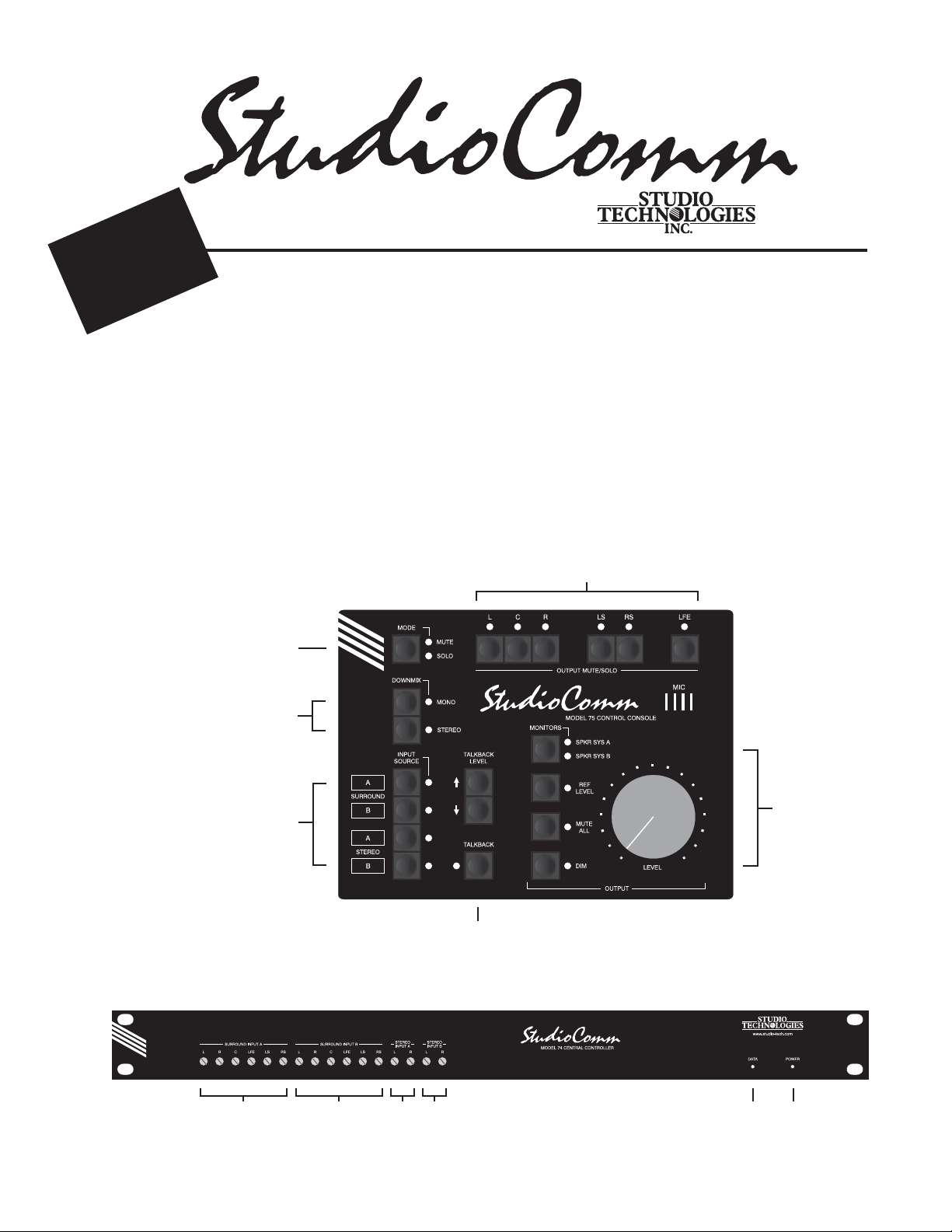
Monitor output
channel mute
Mute / solo
mode select
Downmix
• Stereo to Mono
• 5.1 to Stereo
/ solo
Input sources
Model 74 Central Controller Front Panel
Surround Input A
trim pots
Surround Input B
trim pots
Stereo Input A
trim pots
Stereo Input B
trim pots
Talkback
functions
Model 74 Control Console Front Panel
Monitor output
• Speaker system
• Reference level
• Mute all
• Dim
• Rotary level control
Data
Powe r
active
present
LED
LED
50220-0106, Issue 1
Page 2
Overview
A complete StudioComm for Surround 74/75 system begins with the Model 75 Control Console, a
compact user control surface that is intuitive and comfortable to use. It is designed to reside at the
operator’s location. The Model 75 connects to the Model 74 Central Controller using a single 9-pin
cable. Occupying one rack space, the Model 74 provides all audio input and output circuitry, signal
routing and control, and power supply functions. To complete the system up to four Model 35 Talent
Amplifi er modules can be added. These connect to the Model 74 using standard 3-pin XLR-type audio
cables. Model 35 units are typically deployed in voice-over booths, studio areas, or other locations
where voice or music talent needs access to a headphone cue feed. Each unit provides a stereo audio
amplifi er, user controls, and support for one or two pairs of headphones.
Model 74
Model 74 Central Controller
The Model 74 Central Controller is a single rack-space unit that contains analog, digital, and power
supply electronics. Four analog sources can be connected: two surround (5.1) and two stereo. In many
applications the fi rst surround input, Surround A, will be connected to a multi-channel output on an
audio console or digital audio workstation. The second surround input, Surround B, will be connected
to a playback device, such as a multitrack tape recorder or disk storage system. For fi lm or video post
applications Surround A would be considered the direct source, while Surround B would be considered the playback source.
The two stereo inputs, Stereo A and Stereo B, are provided for general-purpose use and can be connected to a variety of 2-channel direct and playback sources. For fl exibility, the surround and stereo
inputs are compatible with balanced or unbalanced signals having a nominal level range of –12 dBV
to +6 dBu. Fi een-turn trim potentiometers are used to precisely calibrate the input signals.
The Model 74 provides two 6-channel monitor outputs. A powerful system feature is the ability
to confi gure the monitor outputs to meet the exact needs of an installation. In a “straight-ahead”
application the monitor outputs might be confi gured to support two independent surround (5.1)
loudspeaker systems. Alternately, one surround and one stereo monitor system could be connected.
However, other more unique confi gurations are also possible. These include supporting alternate
surround monitor speaker systems or adding additional LFE or surround speakers. The monitor outputs are electronically balanced and designed for connection to audio power amplifi ers or amplifi ed
loudspeakers. Protection circuitry provides power-up and power-down protection of the connected
loudspeaker systems.
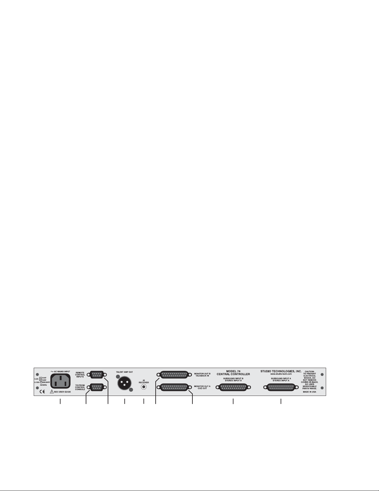
Audio input and output connections are made using four 25-pin D-subminiature connectors. The
Model 74’s audio path features low-noise, low-distortion analog switches for input source selection
and laser-trimmed voltage-controlled-amplifi er (VCA) integrated circuits for monitor level control.
One 9-pin D-subminiature connector is used to connect the Model 74 to the Model 75 Control Console.
A second 9-pin “D-sub” connector is used to interface remote control signals with the Model 74. The
Model 74’s talent amplifi er output uses a 3-pin male XLR-type connector. An infrared receiver module
can connect to the Model 74 using a 3.5 mm jack.
Model 74 Central Controller Back Panel
AC mains
input
connection
Studio Technologies, Inc. Model 74 & Model 75, Issue 1, Page 2
To/from
Model 75
Control
Console
Remote
control
inputs
Output to
Model 35
Talent
Amplifiers
Infrared
receiver
input
Monitor B
output and
line-level
talkback input
Monitor A and
line-level cue
audio outputs
Surround B and
stereo B inputs
Surround A and
stereo A inputs
Page 3

An advanced 8-bit microcontroller provides the logic “horsepower” for the Model 74. AC mains power
is connected directly to the Model 74, which is factory selected for 100, 120, or 220/240 V operation. The
internal power supply utilizes two toroidal mains transformers for quiet audio operation.
Model 75
Model 75 Control Console
The Model 75 Control Console is a compact, self-contained unit designed to be located at the operator’s
position. It allows fi ngertip control of all monitoring and talkback parameters. Numerous LED indica-
tors provide complete status information. A major strength of the Model 75 is its ability to confi gure,
under so ware control, many of the operating parameters. All confi guration parameters are stored
in nonvolatile memory. The Model 75 Control Console connects to, and is powered by, the Model 74
Central Controller. The Model 75 generates MIDI system-exclusive messages to control the Model 74.
Remote-control signals connected to the Model 74 Central Controller are routed to the Model 75 via
pins in the 9-pin interconnecting cable.
The Model 75 provides four bu ons and associated LEDs for selection of the surround and stereo
sources to be monitored. While in most cases only one input source will be monitored at a time, multiple inputs can be selected for simultaneous monitoring. This allows two, three, or all four of the inputs
to be combined (“summed”). While there is no independent control of the input levels, this feature can
be useful for creating rough mixes from the source signals. It is also a fast, eff ective means of making a
“seat-of-the-pants” check on the phase relationship between synchronized signals.
The monitor output levels are controlled using a large, easy-to-use rotary control. The “curve” or
“taper” of the level control can be confi gured to match an operator’s preference. The choices available
are true logarithmic and modifi ed logarithmic. The level control auto mute all function allows the
monitor output channels to mute automatically whenever the rotary level control is in its fully counterclockwise (minimum) position. This is useful in applications such as on-air broadcast. By using the
reference level function, the monitor output level can be set to a pre-confi gured value. This is provided
for audio-with-picture applications that require a specifi c monitor level. The reference level is easily
confi gured by taking an electronic “snapshot” of the position of the rotary level control.
One bu on controls which monitor output, A or B, is active. For operator convenience, the dim func-
tion allows the monitor output level to be reduced by a fi xed dB amount. The dim level is confi gured
from four available levels. A mute all function allows all of the monitor output channels to be simultaneously muted. The mute/solo section provides individual output channel control. One pushbu on
switch sets the operating mode for either mute or solo. In the mute mode, individual channels can be
muted as required. In the solo mode, one channel can be monitored while the others are automatically
muted. Depending on the confi guration, multiple channels can be simultaneously selected for “solo-
ing.” The fl exibility of having both mute and solo available allows an operator to quickly select the
most comfortable and productive operating mode.
Two functions allow the format of the monitored sources to be checked for level or phase inconsistencies. The 5.1 to stereo downmix function is used to create a stereo signal from a 5.1 (surround) source.
The stereo to mono downmix function allows a stereo signal to be added (summed) and monitored.
The two downmix functions can be simultaneously enabled, allowing a surround signal to be checked
for mono compatibility. The operating mode of the stereo to mono downmix function can be selected
from two choices: mono-to-le -and-right or mono-to-center. This allows support for both music
and audio-with-picture applications. A bandpass fi lter feature is associated with the stereo to mono
downmix function. It is included to assist an operator in determining compatibility with “real world”
playback environments. A bandpass fi lter can be inserted into the path of the mono signal, allowing
the response of a monaural loudspeaker associated with an inexpensive television or portable radio to
be simulated.
To support the headphone cue system functions the Model 75 Control Console includes three pushbu on switches and an integral microphone. As expected, one bu on is used to enable the talkback
function. The other two bu ons are used to set the talkback level over an 8-step range. These bu ons
are also used to select which audio source is routed to the headphones. Two choices are provided:
the le and right channels of the source selected for the monitor output, or the le and right channels
associated with Stereo B.
Studio Technologies, Inc. Model 74 & Model 75, Issue 1, Page 3
Page 4

Typically the talkback bu on contained in the Model 75 will be used to initiate the talkback function.
However, some applications may benefi t from having remote activation of talkback. The system pro-
vides several ways of accomplishing this.
In many cases the talkback bu on contained in the Model 75 will be used to initiate the talkback
function. However, some applications may benefi t from being able to remotely activate talkback. A
hard-wired signal can be connected to the remote talkback input. In this way various types of external
wired and wireless equipment can be interfaced. An infrared (IR) receiver module can also be directly
connected. This allows the use of a wireless transmi er to enable talkback. The microphone contained
within the Model 75 Control Console provides crisp, clear talkback audio. But some installations may
benefi t from using an alternate source of talkback audio. This capability is provided by the Model 74’s
line-level talkback audio input.
For fl exibility, the system is designed to easily integrate with recording consoles, specialized playback
systems, and audio-for-picture machine-control electronics. Four hard-wired remote-control input
functions are provided: mute all, dim, talkback, and input select. By providing access to the StudioComm’s mute all and dim functions, talkback or slate activity from an audio console or other communications system can control the monitor output level. The remote talkback input allows an externally
provided contact closure or logic signal to control the talkback function. This allows easy integration
with additional wired or wireless talkback devices. The remote input select function is provided expressly for audio post applications, allowing automatic switching of the StudioComm’s input source
whenever the mode of a recording system changes between playback and record. This function,
referred historically as PEC/direct switching, allows accurate monitoring during dialog replacement,
Foley, or other overdub sessions.
Model 35
In most cases Model 35 Talent Amplifi er modules will serve as the user’s headphone control center.
Each Model 35 contains amplifi er circuitry, stereo level control, mono switch, and two output jacks.
For convenience, a microphone mounting stand adapter is included with each Model 35. In addition
to the talent amplifi er output, the Model 74 also provides a stereo line-level cue output. This allows
interfacing with other headphone cue systems or could connect to a transmission system associated
with a remotely located studio or control room. The line-level cue output can also serve as a source of
“slate” audio for workstations.
Model 35 Talent Amplifier Front Panel
Level control
Stereo/mono
switch
Headphone
outputs
Model 35 Talent Amplifier Back Panel
To additional
Model 35
Talent Amplifiers
From Model 74
or another Model 35’s
loop thru connector
Studio Technologies, Inc. Model 74 & Model 75, Issue 1, Page 4
Page 5

Specifications Model 74 Central Controller
General Audio:
Frequency Response: 20 Hz-20 kHz ±0.1 dB (down 0.5 dB
@ 60 kHz), monitor outputs
Model 74
&
Model 75
Distortion (THD+N): 0.0
monitor outputs
S/N Ratio: 87 dB, ref +4 dBu out, 20 Hz-20 kHz, monitor
outputs
Crosstalk: 78 dB, typical, ref +4 dBu in, 20 Hz-20 kHz,
monitor outputs
Audio Inputs: 16, organized as two 6-channel “5.1” inputs
and two 2-channel “stereo” inputs
Type: electronically balanced, compatible with balanced or
unbalanced sources
Impedance: 24 k ohms
Nominal Level: –12 dBV to +6 dBu, adjustable
Level Calibration: 15-turn trim potentiometers
Monitor Outputs: 2, 6-channel
Type: electronically balanced, compatible with balanced or
unbalanced loads
Maximum Level: +27 dBu into 10 k ohms, +26 dBu into
600 ohms
Talent Amplifi er Output:
Compatibility: provides power and audio signals for up to
four Model 35 Talent Amplifi ers
Type: DC power with two channels of unbalanced audio
Connections: common on pin 1, DC (+27 volts nominal,
200 milliamperes maximum) modulated with channel 1
audio (–10 dBu nominal) on pin 2, and channel 2 audio
(–10 dBu nominal) on pin 3
Line-Level Cue Output: 1, stereo
Nominal Level: +4 dBu, nominal
Type: electronically balanced, capacitor-coupled, intended
to drive balanced or unbalanced loads of 600 ohms or
greater
Source Impedance: 100 ohms, nominal
Maximum Level: +20 dBu into 10 k ohms
Line-Level Talkback Input:
Level: +4 dBu, nominal
Type: electronically balanced
Impedance: 24 k ohms, nominal
Infrared Receiver Input:
Type: intended for use with industry-standard receiver
module; data rate 650 baud
Remote Control Inputs: 4
Type: +5 volts DC logic, activates on closure to system
common
Functions: mute, dim, talkback, input select
Downmix:
Functions: 5.1 to stereo, stereo to mono (mono-to-le -and-
right, mono-to-center)
5.1 to Stereo: LS @ –3 dB summed with L; RS @ –3 dB
summed with R, C @ –6 dB summed with L and R; LS, RS,
and LFE monitor outputs mute
Stereo to Mono (Mono-to-Le -and-Right): L summed
with R to L and R or L summed with R to C; a enuation
independently confi gurable; C, LS, RS, and LFE monitor
outputs mute
Stereo to Mono (Mono-to-Center): L summed with R to C;
a enuation independently con
LFE monitor outputs mute
4%, measured at 1 kHz, +4 dBu,
fi gurable; L, R, LS, RS, and
Stereo to Mono (Mono-to-Center) Bandpass Filter:
Response: –3 dB @ 100 Hz and 5 kHz, nominal,
12 dB/octave
Connectors:
Audio: 4, 25-pin D-subminiature female
Talent Amplifi er Output: 3-pin male XLR-type
To/From Model 75: 9-pin D-subminiature female
Remote Control Inputs: 9-pin D-subminiature female
Infrared Receiver Input: 3.5 mm 3-conductor jack
AC Mains: 3-blade, IEC 320 C14-compatible (mates with
IEC 320 C13)
AC Mains Requirement:
100, 120, or 220/240 V, ±10%, factory confi gured, 50/60 Hz,
26 wa s maximum
Dimensions (Overall):
19.00 inches wide (48.3 cm)
1.72 inches high (4.4 cm)
9.58 inches deep (24.3 cm)
Mounting: one space in a standard 19-inch rack
Weight: 9.5 pounds (4.3 kg)
Model 75 Control Console
Application: supports Model 74 Central Controller
Power: provided by Model 74 Central Controller
Output Data: generates MIDI system-exclusive messages
Connector: 9-pin D-subminiature female
Dimensions (Overall):
7.2 inches wide (18.3 cm)
2.2 inches high (5.6 cm)
5.4 inches deep (13.7 cm)
Weight: 1.8 pounds (0.82 kg)
Model 35 Talent Amplifier
Load: intended for connection to one or two pairs of
headphones with total impedance of 75 ohms or greater
Maximum Output Voltage: 16 V peak-to-peak into 150
ohms @ 1% THD+Noise
Distortion (THD+N): 0.03%
Frequency Response: 20 Hz-20 kHz ±0.5 dB
Dimensions (Overall):
4.2 inches wide (10.7 cm)
2.0 inches high (5.1 cm)
5.3 inches deep (13.5 cm)
Weight: 0.8 pounds (0.7 kg)
Specifi cations subject to change without notice.
© by Studio Technologies, Inc., January 2006.
For further information please contact:
Studio Technologies, Inc.
5520 West Touhy Ave.
Skokie, Illinois 60077 USA
Telephone (847) 676-9177
Fax (847) 982-0747
www.studio-tech.com
Studio Technologies, Inc. Model 74 & Model 75, Issue 1, Page 5
 Loading...