

Page 1
for Surround
Model 74 Central Controller and
Model 75 Control Console
User Guide
Issue 2, January 2006
This User Guide is applicable for systems consisting of:
Model 74: serial number M74-00151 and later;
Model 75: M75-00151 and later
© 2006 by Studio Technologies, Inc., all rights reserved
www.studio-tech.com
50221-0106, Issue 2
Page 2

Table of Contents
Introduction ................................................................... 5
Installation .................................................................... 9
Confi guration ................................................................16
Operation ...................................................................... 34
Technical Notes ............................................................39
Specifi cations ...............................................................44
Appendix A – MIDI Messages ......................................45
Block Diagrams
Model 74 Central Controller
Model 75 Control Console
Page 3

for Surround
This page intentionally left blank.
Issue 2, January 2006 Model 74/75 User Guide
Page 4 Studio Technologies, Inc.
Page 4

for Surround
Introduction
What This User Guide Covers
This User Guide is designed to assist you
when installing and using the Model 74
Central Controller and the Model 75
Control Console.
StudioComm for Surround
The StudioComm for Surround Model 74
Central Controller and Model 75 Control
Console work together to provide 5.1
surround and stereo source monitoring
capabilities, along with a full-featured
headphone “talkback” cue system. The
system is a perfect fi t for contemporary
facilities that need to perform a variety of
audio tasks. These can include surround
and stereo mixing and monitoring, live recording of voice, music, and sound effects,
and on-air broadcast applications. The
system’s features were carefully selected
to provide extensive capabilities while
remaining simple to operate. Of overriding
concern is maintaining the quality of the
connected audio sources. This is accomplished using a combination of excellent
circuit design and carefully selected components. The Model 74/Model 75 combination is ideal for adding surround monitoring
capability to disk-based recording systems.
It’s also well suited for upgrading a postproduction or broadcast facility to support
multi-channel monitoring.
A complete StudioComm for Surround
74/75 system begins with the Model 75
Control Console, a compact user control
surface that is intuitive and comfortable to
use. It is designed to reside at the operator’s location. The Model 75 connects
to the Model 74 Central Controller using
a single 9-pin cable. Occupying one rack
space, the Model 74 provides all audio
input and output circuitry, signal routing
and control, and power supply functions.
To complete the system up to four Model
35 Talent Amplifi er modules can be added.
These connect to the Model 74 using standard 3-pin XLR-type audio cables. Model
35 units are typically deployed in voiceover booths, studio areas, or other locations where voice or music talent needs
access to a headphone cue feed. Each
unit provides a stereo audio amplifi er, user
controls, and support for one or two pairs
of headphones.
Model 74 Central Controller
The Model 74 Central Controller is a
single rack-space unit that contains analog, digital, and power supply electronics.
Four analog sources can be connected:
two surround (5.1) and two stereo. In
many applications the fi rst surround input,
Surround A, will be connected to a multichannel output on an audio console or
digital audio workstation. The second surround input, Surround B, will be connected
to a playback device, such as a multitrack
tape recorder or disk storage system. For
fi lm or video post applications Surround
A would be considered the direct source,
while Surround B would be considered
the playback source.
The two stereo inputs, Stereo A and
Stereo B, are provided for general-purpose
use and can be connected to a variety
of 2-channel direct and playback sources.
For fl exibility, the surround and stereo
inputs are compatible with balanced or
unbalanced signals having a nominal level
range of –12 dBV to +6 dBu. Fifteen-turn
trim potentiometers are used to precisely
calibrate the input signals.
Model 74/75 User Guide Issue 2, January 2006
Studio Technologies, Inc. Page 5
Page 5
for Surround
The Model 74 provides two 6-channel
monitor outputs. A powerful system feature
is the ability to confi gure the monitor out-
puts to meet the exact needs of an installation. In a “straight-ahead” application
the monitor outputs might be confi gured
to support two independent surround (5.1)
loudspeaker systems. Alternately, one
surround and one stereo monitor system
could be connected. However, other more
unique confi gurations are also possible.
These include supporting alternate surround monitor speaker systems or adding
additional LFE or surround speakers. The
monitor outputs are electronically balanced
and designed for connection to audio power amplifi ers or amplifi ed loudspeakers.
Protection circuitry provides power-up and
power-down protection of the connected
loudspeaker systems.
Audio input and output connections are
made using four 25-pin D-subminiature
connectors. The Model 74’s audio path
features low-noise, low-distortion analog
switches for input source selection and
laser-trimmed voltage-controlled-amplifi er
(VCA) integrated circuits for monitor level
control. One 9-pin D-subminiature connector is used to connect the Model 74 to
the Model 75 Control Console. A second
9-pin “D-sub” connector is used to interface remote control signals with the Model
74. The Model 74’s talent amplifi er output
uses a 3-pin male XLR-type connector. An
infrared receiver module can connect to
the Model 74 using a 3.5 mm jack.
An advanced 8-bit microcontroller provides
the logic “horsepower” for the Model 74.
AC mains power is connected directly to
the Model 74, which is factory selected
for 100, 120, or 220/240 V operation.
The internal power supply utilizes two
toroidal mains transformers for quiet
audio operation.
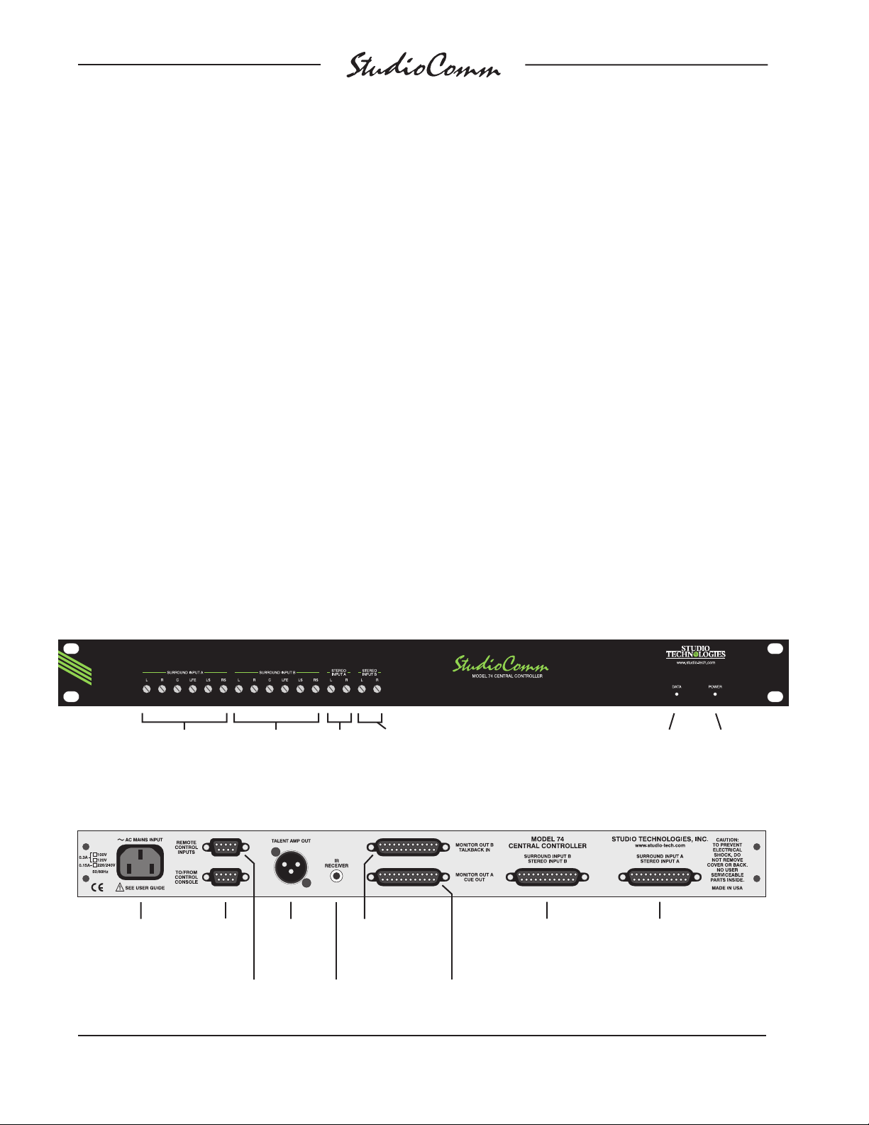
Figure 1. Model 74 Central Controller Front Panel
Surround
Input A
trim pots
Surround
Input B
trim pots
Stereo
Input A
trim pots
Stereo
Input B
trim pots
Figure 2. Model 74 Central Controller Back Panel
AC mains
input connection
To/from
Model 75
Control
Console
Remote
control
inputs
Output to
Model 35
Talent
Amplifi ers
Monitor B output
and line-level
talkback input
Infrared
receiver
input
Monitor A output and
line-level cue audio
outputs
Surround Input B
and Stereo Input B
connections
Data
active LED
Surround Input A
and Stereo Input A
connections
Power
present LED
Issue 2, January 2006 Model 74/75 User Guide
Page 6 Studio Technologies, Inc.
Page 6
for Surround
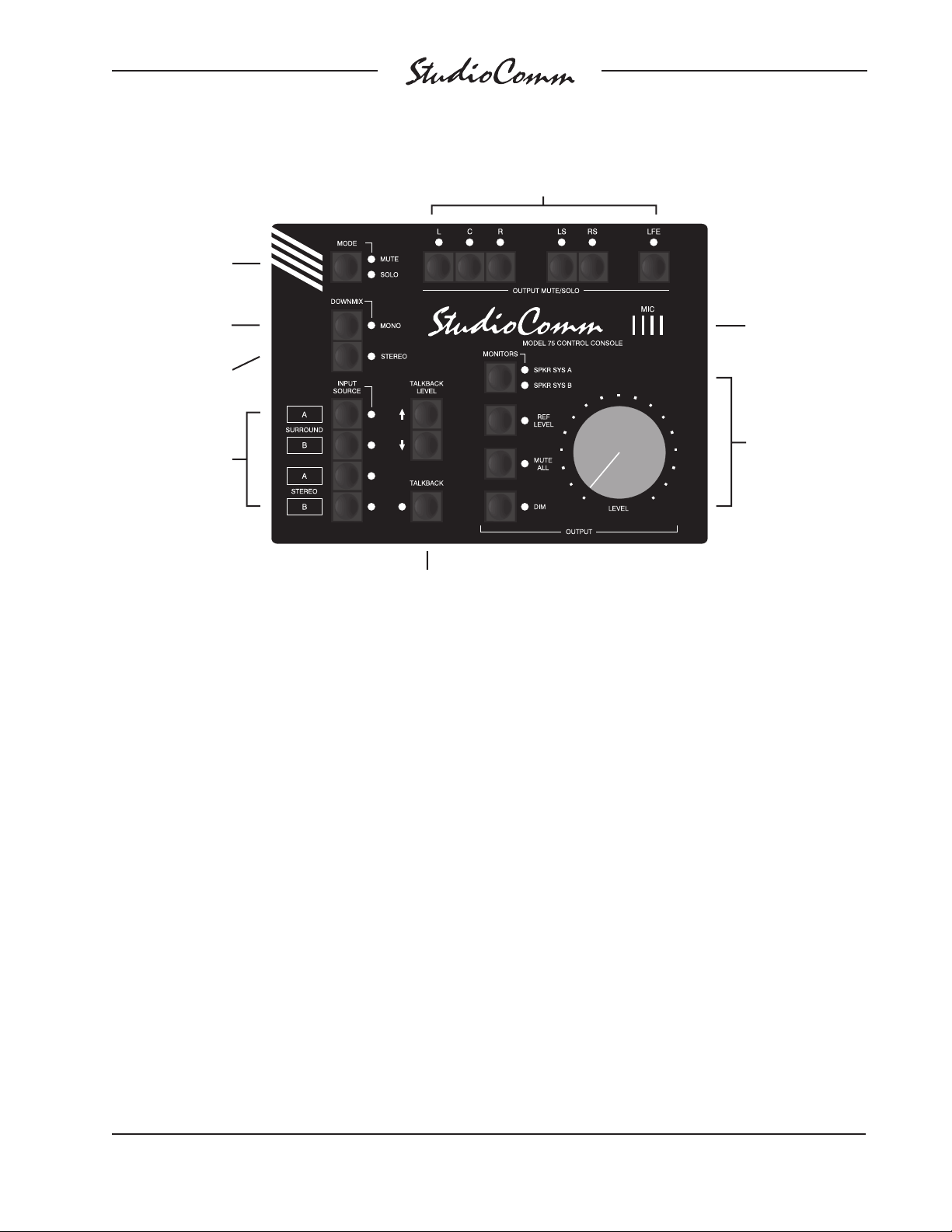
Figure 3. Model 75 Control Console Front Panel
Mute/solo
mode select
Monitor output
channel mute/solo
Stereo to mono
downmix
5.1 to stereo
downmix
Input
sources
Talkback
Model 75 Control Console
The Model 75 Control Console is a compact, self-contained unit designed to be
located at the operator’s position. It allows
fi ngertip control of all monitoring and talkback parameters. Numerous LED indicators provide complete status information. A
major strength of the Model 75 is its ability
to confi gure, under software control, many
of the operating parameters. All confi gura-
tion parameters are stored in nonvolatile
memory. The Model 75 Control Console
connects to, and is powered by, the Model
74 Central Controller. The Model 75 generates MIDI system-exclusive messages
to control the Model 74. Remote-control
signals connected to the Model 74 Central
Controller are routed to the Model 75 via
pins in the 9-pin interconnecting cable.
The Model 75 provides four buttons and
associated LEDs for selection of the surround and stereo sources to be monitored.
Talkback
microphone
Monitor Output
• Speaker system
select
• Reference level
• Mute all
• Dim
• Rotary level control
While in most cases only one input source
will be monitored at a time, multiple inputs
can be selected for simultaneous monitoring. This allows two, three, or all four of
the inputs to be combined (“summed”).
While there is no independent control of
the input levels, this feature can be useful
for creating rough mixes from the source
signals. It is also a fast, effective means of
making a “seat-of-the-pants” check on the
phase relationship between synchronized
signals.
The monitor output levels are controlled
using a large, easy-to-use rotary control.
The “curve” or “taper” of the level control
can be confi gured to match an operator’s
preference. The choices available are true
logarithmic and modifi ed logarithmic. The
level control auto mute all function allows
the monitor output channels to mute automatically whenever the rotary level control
is in its fully counterclockwise (minimum)
Model 74/75 User Guide Issue 2, January 2006
Studio Technologies, Inc. Page 7
Page 7

for Surround
position. This is useful in applications such
as on-air broadcast. By using the reference level function, the monitor output
level can be set to a pre-confi gured value.
This is provided for audio-with-picture applications that require a specifi c monitor
level. The reference level is easily confi g-
ured by taking an electronic “snapshot” of
the position of the rotary level control.
One button controls which monitor output, A or B, is active. For operator convenience, the dim function allows the monitor
output level to be reduced by a fi xed dB
amount. The dim level is confi gured from
four available levels. A mute all function
allows all of the monitor output channels
to be simultaneously muted. The mute/solo
section provides individual output channel
control. One pushbutton switch sets the
operating mode for either mute or solo. In
the mute mode, individual channels can
be muted as required. In the solo mode,
one channel can be monitored while the
others are automatically muted. Depending on the confi guration, multiple channels
can be simultaneously selected for “soloing.” The fl exibility of having both mute and
solo available allows an operator to quickly
select the most comfortable and productive
operating mode.
Two functions allow the format of the
monitored sources to be checked for
level or phase inconsistencies. The 5.1
to stereo downmix function is used to
create a stereo signal from a 5.1 (surround) source. The stereo to mono downmix function allows a stereo signal to be
added (summed) and monitored. The two
downmix functions can be simultaneously
enabled, allowing a surround signal to be
checked for mono compatibility. The operating mode of the stereo to mono downmix
function can be selected from two choices:
mono-to-left-and-right or mono-to-center.
This allows support for both music and
audio-with-picture applications. A bandpass
fi lter feature is associated with the stereo
to mono downmix function. It is included to
assist an operator in determining compatibility with “real world” playback environments. A bandpass fi lter can be inserted
into the path of the mono signal, allowing
the response of a monaural loudspeaker
associated with an inexpensive television
or portable radio to be simulated.
To support the headphone cue system
functions the Model 75 Control Console
includes three pushbutton switches and
an integral microphone. As expected, one
button is used to enable the talkback function. The other two buttons are used to set
the talkback level over an 8-step range.
These buttons are also used to select
which audio source is routed to the headphones. Two choices are provided: the left
and right channels of the source selected
for the monitor output, or the left and right
channels associated with Stereo B.
In many cases the talkback button contained in the Model 75 will be used to initiate the talkback function. However, some
applications may benefi t from being able
to remotely activate talkback. A hard-wired
signal can be connected to the remote
talkback input. In this way various types
of external wired and wireless equipment
can be interfaced. An infrared (IR) receiver
module can also be directly connected.
This allows the use of a wireless transmitter to enable talkback. The microphone
contained within the Model 75 Control
Console provides crisp, clear talkback
audio. But some installations may benefi t
from using an alternate source of talkback
audio. This capability is provided by the
Model 74’s line-level talkback audio input.
Issue 2, January 2006 Model 74/75 User Guide
Page 8 Studio Technologies, Inc.
Page 8
for Surround
For fl exibility, the system is designed to
easily integrate with recording consoles,
specialized playback systems, and audiofor-picture machine-control electronics.
Four hard-wired remote-control input functions are provided: mute all, dim, talkback,
and input select. By providing access to
the StudioComm’s mute all and dim functions, talkback or slate activity from an
audio console or other communications
system can control the monitor output
level. The remote talkback input allows
an externally provided contact closure or
logic signal to control the talkback function.
This allows easy integration with additional
wired or wireless talkback devices. The
remote input select function is provided
expressly for audio post applications, allowing automatic switching of the StudioComm’s input source whenever the mode
of a recording system changes between
playback and record. This function, referred historically as PEC/direct switching,
allows accurate monitoring during dialog
replacement, Foley, or other overdub
sessions.
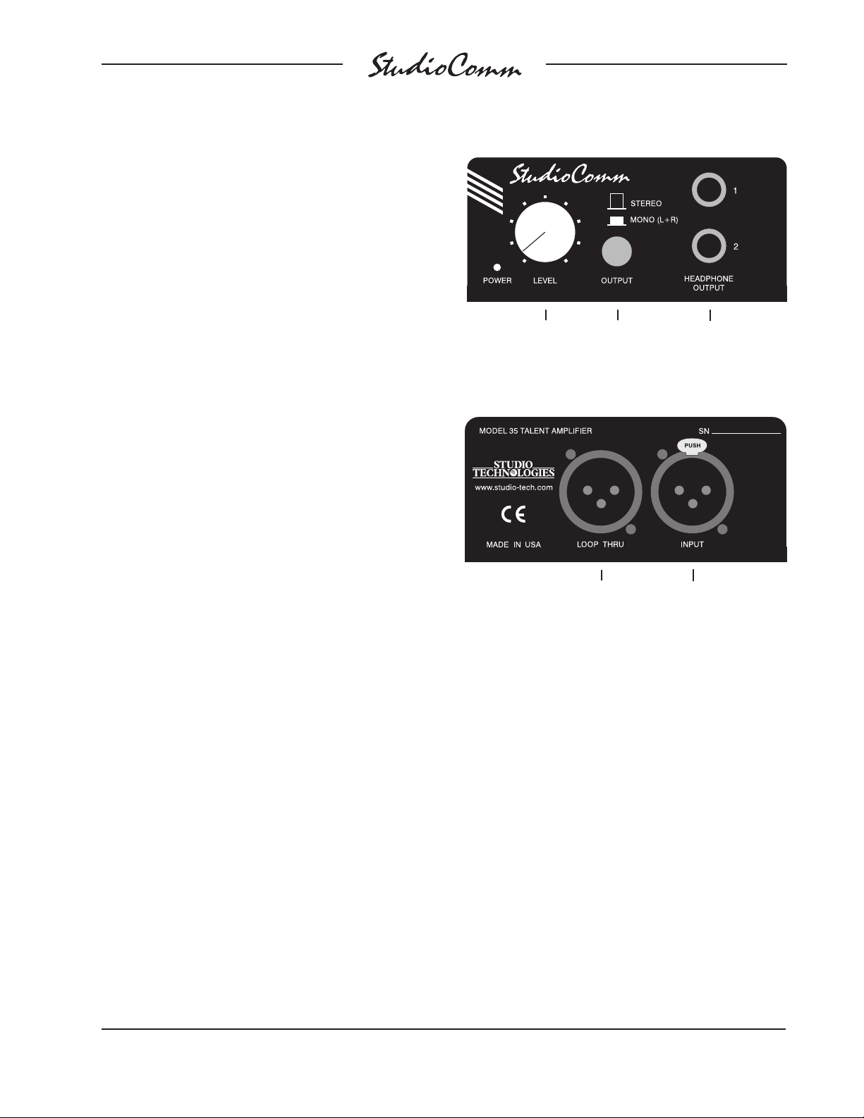
Figure 4. Model 35 Talent Amplifi er Front Panel
Level control
Figure 5. Model 35 Talent Amplifi er Back Panel
Stereo/
mono
switch
To additional
Model 35
Talent Amplifi ers
Headphone
outputs
From Model 74
or another Model 35’s
loop thru connector
In most cases Model 35 Talent Amplifi er
modules will serve as the user’s headphone control center. Each Model 35
contains amplifi er circuitry, stereo level
control, mono switch, and two output jacks.
For convenience, a microphone mounting
stand adapter is included with each Model
35. In addition to the talent amplifi er out-
put, the Model 74 also provides a stereo
line-level cue output. This allows interfacing with other headphone cue systems or
could connect to a transmission system
associated with a remotely located studio
Installation
In this section you will be installing the
Model 74 Central Controller in an equipment rack. Audio input, monitor output,
and headphone cue system connections
will be made. One or more Model 35 Talent Amplifi ers will be connected. A location
will be selected for the Model 75 Control
Console and it will be connected to the
Model 74. If required, external equipment
will be interfaced to the remote control
inputs. AC mains power will be connected
to the Model 74.
or control room. The line-level cue output
can also serve as a source of “slate” audio
for workstations.
Model 74/75 User Guide Issue 2, January 2006
Studio Technologies, Inc. Page 9
Page 9

for Surround
System Components
The shipping carton contains one each of
the following: Model 74 Central Controller,
Model 75 Control Console, 9-pin D-sub
interconnecting cable, and user guide.
Units destined for North America also
include an AC mains cord. Your dealer or
distributor will provide an AC mains cord
for non-North American destination. Model
35 Talent Amplifi ers will be contained in
separate cartons.
Mounting the Model 74
The Model 74 Central Controller requires
one space in a standard 19-inch equipment rack. Select a location that is convenient to both the analog audio signals and
the Model 75 Control Console. A cable
is provided to connect the Model 75 with
the Model 74. Secure the Model 74 into
the equipment rack using two mounting
screws per side.
Audio Connections
the monitor output A and line-level cue
outputs is identical to that of a DA-88-style
output harness. A wiring harness prepared
for the fourth D-sub is slightly different. It is
used for connecting with the six channels
of monitor output B as well as the linelevel talkback input. As such, it will require
careful attention when selecting the right
terminations, e.g., six male plugs and one
female connector. Please refer to Figures
6 through 11 for the exact connection details. Be certain to note that the Model 74’s
D-sub connectors use 4-40 threads.
Unless there’s a special need, it may be
cost and time effective for you to purchase
commercially made cable harnesses. Let
the large market for DA-88-style cabling
help you painlessly install your system!
There is one caveat to using pre-made
harnesses. The sex of the connector
associated with the line-level talkback
input may need to be changed. Even so,
using pre-made cables harnesses may
still provide helpful.
Line-level audio signal connections are
made by way of four 25-pin D-sub connectors, located on the Model 74’s back panel.
To implement all the available features
four cable harnesses, each with a 25-pin
D-sub plug (male) on one end and the
desired connectors on the other end, are
necessary. These cable harnesses are not
supplied by Studio Technologies. Note that
our friends in some locations may use the
term “loom” instead of harness.
The wiring scheme used by the D-sub
connectors comply with that made familiar
by TASCAM® with their DA-88® product.
Wiring harnesses prepared for connecting to the Model 74’s surround and stereo
inputs are identical to DA-88-style input
harnesses. A wiring harness prepared for
Issue 2, January 2006 Model 74/75 User Guide
Page 10 Studio Technologies, Inc.
Surround and Stereo Inputs
The connector labeled Surround Input A
and Stereo Input A, as well as the
connector labeled Surround Input B and
Stereo Input B are used to interface with
the two 6-channel (5.1 surround) and two
2-channel (stereo) input circuits. Please
refer to Figures 6 and 7 for details on the
exact “pin out” of the D-sub connectors.
Each input circuit is electronically balanced
and intended for connection to balanced
or unbalanced sources with nominal signal levels of –12 dBV to +6 dBu. A 15-turn
trim potentiometer is associated with each
input channel, allowing the input sensitivity
to be adjusted to match the source’s level.
The confi guration section of this guide pro-
vides details on using the trim pots.
Page 10
for Surround
Signal Signal
Connections High (+) Low (–) Shield
SURROUND A-L 24 12 25
SURROUND A-R 10 23 11
SURROUND A-C 21 9 22
SURROUND A-LFE 7 20 8
SURROUND A-LS 18 6 19
SURROUND A-RS 4 17 5
STEREO A-L 15 3 16
STEREO A-R 1 14 2
Notes: 1) Connector type on Model 74 is 25-pin D-subminiature
female. Installer must provide plug (male). Connector
uses 4-40 threaded inserts for locking with mating plug.
2) Wiring scheme follows TASCAM DA-88 convention.
Standard DA-88-type wiring harnesses are directly
compatible, with the exception of 4-40 screw threads
being required.
Figure 6. Connections for Inputs Surround A
and Stereo A
Balanced sources should be wired so that
signal high is connected to +, signal low to
–, and shield to the shield connection. With
an unbalanced source, connect signal high
to the + connection, and shield to both the
– and the shield connections. If connecting
to an unbalanced source in this manner results in hum or noise, try connecting signal
high to +, and shield to –; leave the shield
connection unterminated.
It is highly recommended that at least one of
the surround inputs be wired by way of an
audio patch bay. This will allow the channels associated with that input source to be
easily rerouted. While signals generated
within a facility will normally follow a specifi c
format, such as left, right, center, LFE, left
surround, and right surround, it is possible
that media provided by an outside facility
will follow a different scheme.
Signal Signal
Connections High (+) Low (–) Shield
SURROUND B-L 24 12 25
SURROUND B-R 10 23 11
SURROUND B-C 21 9 22
SURROUND B-LFE 7 20 8
SURROUND B-LS 18 6 19
SURROUND B-RS 4 17 5
STEREO B-L 15 3 16
STEREO B-R 1 14 2
Notes: 1) Connector type on Model 74 is 25-pin D-subminiature
female. Installer must provide plug (male). Connector
uses 4-40 threaded inserts for locking with mating plug.
2) Wiring scheme follows TASCAM DA-88 convention.
Standard DA-88-type wiring harnesses are directly
compatible, with the exception of 4-40 screw threads
being required.
Figure 7. Connections for Inputs Surround B
and Stereo B
Monitor Outputs
Two connectors are used to support the
two 6-channel (5.1 surround) monitor outputs. Please refer to Figures 8 and 9 for
details on the exact “pin outs” of the D-sub
connectors.
The monitor output channels are intended
for connection to audio amplifi ers associ-
ated with monitor loudspeakers, or to the
inputs of loudspeakers that contain integrated amplifi ers. The monitor outputs are
electronically balanced and capable of
driving balanced or unbalanced loads of 600
ohms or greater. While balanced operation
is preferred, unbalanced operation does
not pose a problem. To connect to an unbalanced load connect the + terminal as signal
high, and both the – and shield as the signal
low/shield. For optimal unbalanced operation, it is important to connect both – and
shield together directly on the D-sub plug,
not at the other end of the harness.
Model 74/75 User Guide Issue 2, January 2006
Studio Technologies, Inc. Page 11
Page 11
for Surround
Signal Signal
Connections High (+) Low (–) Shield
MONITOR OUT A-L 24 12 25
MONITOR OUT A-R 10 23 11
MONITOR OUT A-C 21 9 22
MONITOR OUT A-LFE 7 20 8
MONITOR OUT A-LS 18 6 19
MONITOR OUT A-RS 4 17 5
CUE OUT-L 15 3 16
CUE OUT-R 1 14 2
Notes: 1) Connector type on Model 74 is 25-pin D-subminiature
female. Installer must provide plug (male). Connector
uses 4-40 threaded inserts for locking with mating plug.
2) Wiring scheme follows TASCAM DA-88 convention.
Standard DA-88-type wiring harnesses are directly
compatible, with the exception of 4-40 screw threads
being required.
Figure 8. Connections for Monitor Output A and
Line-Level Cue Outputs
Signal Signal
Connections High (+) Low (–) Shield
MONITOR OUT B-L 24 12 25
MONITOR OUT B-R 10 23 11
MONITOR OUT B-C 21 9 22
MONITOR OUT B-LFE 7 20 8
MONITOR OUT B-LS 18 6 19
MONITOR OUT B-RS 4 17 5
UNUSED 15 3 16
TALKBACK INPUT 1 14 2
Notes: 1) Connector type on Model 74 is 25-pin D-subminiature
female. Installer must provide plug (male). Connector
uses 4-40 threaded inserts for locking with mating plug.
2) Wiring scheme follows TASCAM DA-88 convention.
Standard DA-88-type wiring harnesses are directly
compatible, with the exception of 4-40 screw threads
being required.
Note that while the Model 74’s electronically
balanced output circuits are capable of driving loads of 600 ohms or greater, the output
level will drop slightly as the load impedance
approaches 600 ohms. A 0.5 dB difference
in output level can be expected as the load
impedance changes from 10 k ohms to 600
ohms. This drop is not insignifi cant and leads
to the recommendation that input loads be
10 ohms or greater.
It’s important to note that the two 6-channel
monitor outputs can be used to create a
wide variety of monitor system implementations. Confi guration choices allow the two
outputs to perform tasks more nuanced
than just serving as a 6-channel A/B
switching matrix. Please carefully review
the confi guration section of this user guide
prior to connecting to the monitor outputs;
don’t let the system’s unique fl exibility go
underutilized!
Headphone Cue System
Two outputs and one input are associated
with the headphone cue system. The talent
amplifi er output supplies audio and DC
power for supporting Model 35 Talent
Amplifi er units. Using this method a great-
sounding, fl exible cue system can be easily
created. A stereo line-level output associated with the headphone cue system is also
available. A source of line-level audio can be
connected and can serve as the talkback audio source. This source can be used in place
of the microphone contained in the Model 75
Control Console.
Figure 9. Connections for Monitor Output B and
Line-Level Talkback Inputs
Talent Amplifi er Output
Up to four Model 35 Talent Amplifi ers can
be connected to the Model 74’s talent amplifi er output. The output connector is a 3-pin
male XLR-type. For best performance, use
low-capacitance shielded microphone-type
Issue 2, January 2006 Model 74/75 User Guide
Page 12 Studio Technologies, Inc.
Page 12
for Surround
cable to distribute the talent amplifi er
signal. If there is a choice, select cables
with the heaviest wire gauge commonly
available. This will reduce voltage drop
when using long cable runs. Refer to the
Technical Notes section for additional
information.
The simplest installation would use a
microphone cable to connect the Model 74
to the fi rst talent amplifi er; the loop through
connector on that talent amp sending the
signal on to the next talent amp.
For convenience, you may want to wire
your facility to allow easy access to the
talent amplifi er signal at all locations where
talent amplifi ers might be used. The tal-
ent amplifi ers connect to the Model 74 in
parallel, so the connectors on the distribution panels or mult boxes should be wired
in parallel.
Warning: Do not connect the Model
74’s talent amplifi er output to any-
thing but Studio Technologies’ talent
amplifi ers. Some audio equipment
may be damaged by the DC voltage
contained on pin 2 of the talent amplifi er output connector.
be useful for connecting with a remotely
located studio or production facility. Using
ISDN or IP-based technology, being able
to send audio signals to literally any part of
the world has become a fairly simple task.
The headphone cue signals are accessible
on one of the 25-pin D-subminiature connectors, located on the Model 74’s back
panel. Please refer to Figure 8 for details
on the exact “pin out” of the D-sub.
The line-level cue outputs are electronically balanced, capacitor coupled, and
intended to drive balanced or unbalanced
loads of 600 ohms or greater. While balanced operation is preferred, unbalanced
operation does not pose a problem. To
connect to an unbalanced load connect
the + terminal as signal high, and both the
– and shield as the signal low/shield.
Note that while the line-level cue outputs
are electronically balanced, signal is only
driven on the + connection. The – connection serves only as a signal-balancing
return path. This simplifi ed output circuit
was deemed appropriate for headphone
cue system applications. It provides good
audio quality even though its circuitry is not
as sophisticated as that used by the monitor output channels.
Included with each Model 35 Talent
Amplifi er is a nifty mounting adapter that
allows the unit to be conveniently attached
to a microphone stand. Please refer to the
documentation provided in the Model 35’s
shipping carton for details.
Line-Level Talkback Input
An alternate source of talkback audio can
be connected to the Model 74. This audio
source can be used instead of the microphone contained in the Model 75. A confi guration parameter selects which source
Line-Level Cue Output
A 2-channel (stereo) line-level output
provides access to the headphone cue
system signals. The line-level cue output
channel is intended for connection to
an audio amplifi er associated with a
is active.
The audio source should have a nominal
level of +4 dBu and can be balanced or
unbalanced. Pins on one of the 25-pin
D-subminiature connectors are used to
connect the signal. Refer to Figure 9
headphone cue system. It could also
Model 74/75 User Guide Issue 2, January 2006
Studio Technologies, Inc. Page 13
Page 13
for Surround
for details. Balanced sources should be
wired so that signal high is connected to
+, signal low to –, and shield to the shield
connection. With an unbalanced source,
connect signal high to the + connection,
and shield to both the – and the shield
connections. If connecting to an unbalanced source in this manner results in
hum or noise, try connecting signal high to
+, and shield to –; leave the shield connection unterminated.
Remote Control Inputs
Pin Signal
1 Shield
2 Spare A (to Model 74)
3 Spare B (to Model 74)
5 Remote Mute All (to Model 75)
6 Remote Dim (to Model 75)
7 Remote Talkback (to Model 75)
8 Remote Input Select (to Model 75)
9 Remote Control Common (to Model 75)
Notes: 1) Connector type on Model 74 is 9-pin D-subminiature
female. Installer must provide plug (male). Connector
uses 4-40 threaded inserts for locking with mating plug.
Support is provided for four hard-wired remote control input functions: mute all, dim,
talkback, and remote input select. The inputs are “pulled up” to +5 volts DC by way
of resistors and are active when brought to
the logic low state. Inputs of this type are
commonly referred to as GPI inputs. While
the input circuitry is protected from overcurrent and static (ESD) discharge, care
should be taken to prevent nasty signals
from reaching them. The inputs are active
only when held in the low state; they can’t
be confi gured to change state (“latch”) in
response to a logic pulse.
A female 9-pin D-subminiature connector,
labeled Remote Control Inputs, is located
on the back panel of the Model 74. It is
used to interface with the four remote
control inputs. Refer to Figure 10 for exact
connection details. Note that pin 1 (shield)
and pin 9 (remote control common) are
electrically identical. In addition to connecting to system common, they connect to the
Model 74’s chassis and mains earth connection. For convenience, the shield of the
interconnecting cable should be connected
to pin 1 (shield), while the return signals of
the remote control sources should connect
to pin 9 (remote control common).
Figure 10. Connector Pin Out for Remote
Control Inputs
Note that although the remote control
connections are physically made to the
D-sub on the Model 74’s back panel, the
remote control input circuitry is actually
located in the Model 75 Control Console.
Conductors in the cable linking the Model
74 to the Model 75 route the remote control signals to the actual input circuitry.
Connecting the Model 74 to
the Model 75
A cable with 9-pin D-sub plugs (males) on
each end is used to interconnect the Model
74 Central Controller with the Model 75
Control Console. A cable, approximately
20-feet (6.1-meters) long, is provided with
each system. The connector labeled To/
From Control Console on the back panel
of the Model 74 is used to connect to the
Model 75.
Should a cable of different length be required, it should be wired in a one-to-one
fashion for all nine pins. Pin 1 serves as
signal common and must be connected
at both ends. A shield connection for the
Issue 2, January 2006 Model 74/75 User Guide
Page 14 Studio Technologies, Inc.
Page 14
for Surround
Pin Signal Direction
1 Power Supply Common 74 to/from 75
2 +15 Volts DC 74 to 75
3 Data (MIDI System-Exclusive) 75 to 74
4 Data Common 74 to/from 75
5 Remote Mute All 74 to 75 (Note 2)
6 Remote Dim 74 to 75 (Note 2)
7 Remote Talkback 74 to 75 (Note 2)
8 Remote Input Select 74 to 75 (Note 2)
9 Talkback Mic Audio 75 to 74
Notes: 1) Connector types on Model 74 and Model 75 are
9-pin D-subminiature female. Connectors use 4-40
threaded inserts for locking with mating plug.
2) Remote control sources connect to D-sub on
Model 74, then passively route to Model 75 via
74/75 interface D-sub.
Figure 11. Connections between Model 74 and
Model 75
cable should also be connected to pin 1 on
the Model 74’s end. For best performance
the cable generally should not exceed 50
feet (15.3 meters) in length.
The reality is that a cable longer in length
than 50 feet should work correctly, as long
as an excellent-quality cable is utilized.
We defi ne “excellent” as extensive shield-
ing along with very low capacitance. The
low cable capacitance is important as it
limits the amount of data-signal waveform
distortion. As far as determining an actual
maximum length, just test and see how
far away you can go—if it works, it works!
A termination resistor connected from pin
3 to pin 4 at the Model 75’s end of the
interconnecting cable may help to support a longer cable “run.” The value of the
termination resistor should be in the range
of 3.3 k (3300) to 10 k (10000) ohms. A
commonly available ¼-watt, 5% tolerance
resistor is perfectly acceptable.
Infrared Remote Control Input
An infrared (IR) receiver module can be
directly connected to the Model 74. This
allows, with an appropriate IR transmitter,
wireless activation of the talkback function. The IR receiver connects to the Model
74 using a 3.5 millimeter 3-conductor jack
which is located on the back panel. The jack
complies with the standard convention for
IR receiver modules: data on the tip lead,
ground on the ring lead, and 12 volts DC
on the sleeve lead. Compatible modules
are available from a number of companies.
As an example, the Xantech® 291-80 looks
nice and works adequately. For excellent
performance under compact fl orescent light-
ing conditions the Russound® SaphIR 860
Phantom has proven its worth.
For correct wireless talkback operation
selecting and programming a compatible transmitter is necessary. Refer to the
Confi guration section of this user guide for
details.
AC Mains Power
The Model 74 is internally confi gured to
operate from an AC mains power source of
nominal 100, 120, or 220/240 volts, 50/60
hertz. Units shipped to North America are
factory selected for 120 volt operation. Units
bound for Japan must be selected for 100
volts, while our friends “down under” and
in Europe receive units set for 220/240
volts. Before connecting the Model 74 to
AC mains power, check that it is confi gured
to match the local mains voltage. Look on
the back panel (adjacent to the power entry
connector) for the factory-confi gured volt-
age. Note that an incorrect confi guration
could prevent operation, or cause damage to the unit. Should it be necessary to
change the unit’s operating voltage it must
Model 74/75 User Guide Issue 2, January 2006
Studio Technologies, Inc. Page 15
Page 15
for Surround
be performed only at the factory or by a
competent service technician.
The Model 74 uses an IEC-320 C14compatible connector to mate with the
AC mains cord. The wire colors in the AC
mains cord should conform to the internationally recognized CEE color code and
must be wired accordingly:
Connection Wire Color
Neutral (N) Light Blue
Line (L) Brown
Protective Earth (E) Green/Yellow
Safety Warning: The Model 74 does
not contain an AC mains disconnect
switch. As such, the AC mains cord
plug serves as the disconnection
device. Safety considerations require
that the plug and associated outlet
be easily accessible to allow rapid
disconnection of AC mains power
should it prove necessary.
operating parameters of the system should
be set using the Model 75 Control Console’s confi guration mode.
Level Calibration
Sixteen 15-turn trim potentiometers are
located on the front panel of the Model 74
Central Controller. Taking time to carefully adjust the trim pots will ensure that
accurate monitoring can take place. Each
trim pot allows input signals with a nominal
level of –12 dBV to +6 dBu to be utilized.
With care, it’s easy to calibrate the surround and stereo inputs to within onequarter of a dB of the desired value.
The monitor outputs are used as the
measuring point when adjusting the trim
pots. A laboratory-grade audio level meter or equivalent is required for accurate
calibration. In addition, the audio sources
connected to the inputs must be able to
generate continuous audio signals at their
nominal operating level.
As soon as AC mains power is applied, the
Model 74’s power present LED will fl ash
for a few seconds. After the completion of
a software startup interval the power present LED will light steadily. The data active
LED on the Model 74 will fl ash once upon
power up, then briefl y light upon comple-
tion of the Model 75’s power-up sequence.
The Model 75 will go through its own
power-up sequence, lighting each LED in
secession.
Confi guration
After the physical installation has been
completed, several confi guration issues
must be addressed. On the Model 74 the
surround and stereo inputs must be calibrated using the trim potentiometers. The
Issue 2, January 2006 Model 74/75 User Guide
Page 16 Studio Technologies, Inc.
Procedure
This procedure will calibrate the surround
and stereo input channels. The trim pots
will be adjusted in groups corresponding
to their associated input sources.
1. Begin by turning the audio amplifi ers
or amplifi ed speakers to their off state.
This will protect the loudspeakers and
the operator’s ears from possible
damage.
2. Rotate the level control on the Model
75 to the fully clockwise (maximum)
position.
3. Using the Model 75 Control console,
select Surround A as the input source
and Speaker System A as the selected
monitor output.
Page 16

for Surround
4. On the Model 74, connect the audio
level meter to the left channel of monitor output A.
5. Confi rm that the audio source’s left
channel is generating a steady signal
at precisely its reference level.
6. Observing the level meter, adjust
Surround A, trim pot L, to give a precise +4 dBu level at the left channel
output of monitor output A.
7. Disconnect the level meter from the
left channel of the monitor output.
8. Repeat steps 4-7 for the right, center,
LFE, left surround, and right surround
channels of Surround A.
9. Repeat steps 3-8 for Surround B,
Stereo A, and Stereo B. Obviously, the
stereo inputs have only left and right
channels, requiring only that two trim
pots be adjusted for each.
10. After the calibration procedure has
been completed, rotate the level control on the Model 75 to the fully counterclockwise (minimum) position.
11. After ensuring that the Model 75’s level
control is set to minimum, return AC
mains power to the power amps or
amplifi ed speakers.
Model 75 Operating Parameters
Many StudioComm functions can be confi gured to meet the exact needs of your
installation. Here’s an overview of what
you can confi gure:
• Input channels active
• Speaker systems/monitor outputs
• Talkback
• Solo
• Power-up mute all
• Level control response
• Level control audio mute all
• Reference level
• Remote input select
• Dim level
• Remote mute all
• Remote dim
• Remote talkback
• Auto dim off
• Talkback dim
• Mono
The Model 75 confi guration diagrams,
located at the end of this section, give
details on how each parameter is set. An
overview of each confi gurable parameter
is provided in the following paragraphs.
Entering and Exiting the Confi guration
Mode
A small button is located on the back of
the Model 75 Control Console, adjacent
to the 9-pin D-sub connector. Pressing
and holding this button for two seconds
places the Model 75 into the confi guration
mode. In the confi guration mode the Model
75’s array of buttons and LEDs no longer
perform their normal functions, but instead
allow you to observe and change many of
the operating parameters. The mute/solo
mode LEDs light alternately to indicate that
the confi guration mode is active.
To leave the confi guration mode and
return the Model 75 to normal operation,
once again press and hold the confi gure
button for two seconds. Note that confi gu-
ration changes are stored only after the
confi guration mode has been exited.
Model 74/75 User Guide Issue 2, January 2006
Studio Technologies, Inc. Page 17
Page 17

for Surround
Our apologies to those of you who fi nd the
confi gure button a pain to use, but it’s sup-
posed to be that way! Seriously, the top
of the button is slightly recessed from the
back panel, making it harder to accidentally activate. We didn’t want normal operation to cease because someone pushed
the Model 75 into a “rats nest” of music
scores or track sheets!
There is no problem frequently “tweaking” the Model 75’s operating parameters
to achieve the desired performance. The
confi guration data is stored in nonvolatile
memory, which is rated for thousands of
read and write cycles and a retention time
in tens of years.
Input Channels Active
This confi guration is a bit tricky to un-
derstand, but is really quite simple. The
confi guration parameter for the number of
channels active for each input is provided
for those special cases where a source
has less channels than its usual, e.g., less
than six for Surround A or B.
Let’s look at an example. Surround A
is connected to a 6-channel source, so
its default confi guration is fi ne. But the
source for Surround B is special, having
only three channels: left, center, and right.
This makes it not so “cool” for the operator to select Surround B for monitoring, as
the unconnected left surround, right surround, and LFE channels will get routed to
their respective monitor outputs. Will the
unused input channels pick up signifi cant
noise or hum? Unlikely, but why take a
chance at having a problem. Simply use
the input channels active confi guration
function to disable the three unused channels. Now when Surround B is selected,
only the appropriate channels are selected
for monitoring.
Note that when a channel associated with
an input is disabled the input routing circuitry, under software control, no longer
selects it, but the corresponding monitor
output channel does not mute. With our
example, when selecting Surround B, our
mythical L/C/R source, all selected monitor
output channels will remain active, but the
input routing circuitry won’t enable the LS,
RS, and LFE inputs. While to some people
this might seem confusing and possibly a
design fault, it was implemented this way
because the StudioComm system allows
multiple inputs to be simultaneously selected for monitoring; a surround source might
be selected at the same time as a stereo
source. Muting the outputs in response to
a single input channel being selected simply would not do!
A special mode has been included to
disable an input from being accessed by
the operator. This might be useful, for
example, when Stereo B is not connected
to a source, and has no valid reason to
be selected. This might also be useful
when connecting a special source, such
as a house “tie line” or router output, that
shouldn’t normally be accessible. Disabling
an input is simple to perform, just disable
all channels associated with it; six for Surround A and B, two for Stereo A and B. To
confi rm that an input has been disabled, all
LEDs associated with that input will fl ash
on and off. Once the Model 75 is returned
to the normal operating mode the disabled
input cannot be selected.
Speaker Systems/Monitor Outputs
The confi guration parameters associated
with the speaker system selection button
and monitor output channels offer an extremely powerful resource. With just a few
button presses a wide range of monitor
system implementations can be easily
Issue 2, January 2006 Model 74/75 User Guide
Page 18 Studio Technologies, Inc.
Page 18

for Surround
created. But spending time establishing
the goals, and what steps are needed to
achieve them, can prove very valuable.
Studying the confi guration chart may at
fi rst be confusing but should soon cause
comments such as “cool” and “wow, I can
really do that?” to spill out!
Physically, the Model 74 Central
Controller supports the connection of two
6-channel monitor loudspeaker systems.
They are designated A and B. This means
that there are two output connections for
each channel, e.g., two for left, two for
right, two for center, etc. On the Model
75 Control Console a pushbutton allows
speaker system A or speaker system B to
be selected. The confi guration parameters
allow which of the twelve physical outputs are active when speaker system A is
selected, and which of the twelve physical
outputs are active when speaker system
B is selected. There are no restrictions on
what outputs are active in any situation.
Talkback
Four confi gurable parameters are related
to the talkback function. The talkback button on the Model 75 can be confi gured to
operate in either a push-to-talk or latching
(push on/push off) mode.
The talkback function can be set to add
(sum) talkback audio with the selected cue
source. Alternately, it can be confi gured
so that talkback audio will interrupt and
replace the cue source whenever the talkback function is enabled.
The talkback audio source can be selected
from two choices. In most cases it’s appropriate to use the microphone contained
in the Model 75. For more specialized
applications a source connected to the
line-level talkback input can be effective.
A confi guration option enables or disables
the ability to send a source of cue audio
to the talent amplifi er and line-level cue
outputs. Typically this option will be set
for enable. In certain situations it may be
desirable to only send talkback audio out
the talent amplifi er and line-level talkback
outputs. An example of where this setting
could be appropriate is when one of the
line-level talkback outputs is used, along
with an amplifi er and loudspeaker, to cre-
ate a “stage announce” signal.
Solo
Solo operation can be confi gured to sat-
isfy operator preference. The additive solo
mode matches the functionality found in
most recording consoles. In this mode,
multiple channels can be simultaneously
“soloed,” allowing those channels to be
monitored at the same time. Other operators may prefer the exclusive solo mode.
When this mode is selected, only one
channel can be selected for solo at a time.
The additive solo mode is the default
setting.
Power-Up Mute All
By default, upon application of AC mains
power the monitor outputs remain muted
after the system’s power-up sequence
has been performed. Then an operator
must manually press the mute all button
to enable the monitor outputs. There may
be cases where having the monitor output
channels return to their respective states
as left at the time of the previous loss of
AC mains power, allowing normal operation automatically to resume.
Level Control Response
As expected, the level control on the
Model 75 Control Console is used to adjust the output level of the monitor output
Model 74/75 User Guide Issue 2, January 2006
Studio Technologies, Inc. Page 19
Page 19

for Surround
channels. The amount of rotation required
to reach a specifi c level can be selected
from two modes. This can be described as
allowing the “curve” or “taper” of the level
control to be confi gured. The two available
modes are true logarithmic and modifi ed
logarithmic. In the true logarithmic mode
the level control provides a precise logarithmic performance over its entire rotation,
e.g., the output level is half of its maximum
when the control is set at its midpoint, i.e.,
50% of its “travel.” In the true log mode,
normal listening may require the level control to be set to approximately the
“2-o’clock” position.
Other users may be more comfortable
with the response given by the modifi ed
logarithmic mode. This provides a much
greater output level during the fi rst 50% of
the level control’s travel. When confi gured
for the modifi ed log mode, normal listening
may require the level control to be set to
the 11- or 12-o’clock position. The modifi ed log mode more closely matches the
monitor level control performance found in
many audio consoles. As such it is selected as the default mode.
It’s important to note that changing the
level control response mode will impact the
reference level. Changing from modifi ed
log to true log, or vice-versa, will change
the reference level. Technically, the mathematical value stored as the reference
level does not change, but the loudness
that is heard by the operator will change.
Be warned! Changing the level control
response may require the reference level
to be recalibrated.
Level Control Auto Mute All
The level control auto mute all function
automatically mutes the monitor output
channels whenever the rotary level control
is in its fully counterclockwise position. In
some applications it may be desirable to
disable this function. When disabled the
rotary level control adjusts the monitor
output level over the approximately 72 dB
range; no automatic muting takes place.
Reference Level
For audio-with-picture applications it’s critical that mixing be done in reference to a
known monitor loudspeaker level. This is
often referred to as mixing to “85 dB” on
the monitors. The Model 75 Control Console allows a precise monitor output level
setting to be stored, and then enabled by
pressing the button labeled Ref Level.
Setting the reference level is very simple:
1. Set up a precision sound pressure
level (SPL) measuring device at the
desired listening location.
2. Place the StudioComm system in the
normal operating mode, not the confi guration mode. Be certain that the
reference and dim functions are not
active.
3. Use the Model 75 Control Console to
select the input source that contains
the desired reference signal source,
e.g., pink noise.
4. Select the desired monitor output,
speaker system A or B.
5. Observing the SPL meter, adjust the
Model 75’s rotary level control until
the desired reference output level has
been reached.
6. Being careful not to touch the position
of the rotary level control, enter the
confi guration mode by pressing and
holding the confi guration button locat-
ed on the Model 75’s back panel.
Issue 2, January 2006 Model 74/75 User Guide
Page 20 Studio Technologies, Inc.
Page 20

for Surround
7. Once the confi guration mode has been
entered, the monitor outputs will mute.
Press and hold the reference button
until its associated LED lights. This will
take approximately fi ve seconds. The
LED will light to indicate that a “snapshot” of the new reference level has
been taken.
8. To store the new reference level in
memory, exit the confi guration mode
by again pressing and holding the confi gure button.
This level is now permanently stored as
the reference level. Only by repeating the
procedure can the value be changed.
Once the confi guration mode has been
exited, the monitor output channels will
again become active. Confi rm that the cor-
rect level has been stored by pressing the
reference button. The SPL meter should
again display the desired level. If not,
repeat the calibration procedure.
You might wonder why you have to press
and hold the reference button for fi ve sec-
onds before the selected value is stored.
This is provided specifi cally so that some
careless person won’t accidentally change
the reference level while they are “playing
around” in the confi guration mode! Only if
you know the “secret” will you be able to
store a new value.
Remote Input Select
The remote input select function requires
confi guring two parameters: mode and
input to be selected. The mode can be
selected from three choices: disabled, exclusive, and non-exclusive. As expected,
when confi gured for disabled, the function
cannot be activated. When confi gured for
exclusive, whenever the function is activated only the specifi ed input will be active.
When confi gured for non-exclusive, when-
ever the function is activated the specifi ed input will be added (summed) with
any other input or inputs that are already
active. The input can be selected from
among the two surround and two stereo
input sources.
Dim Level
The dim function is used to reduce the
monitor output level by a preset amount.
The reduction is in dB relative to the monitor output’s current level. There are four
dim level values available: 10, 15, 20,
and 25 dB.
Remote Mute All
Two confi guration choices are associated
with the remote mute all function: disabled
and enabled. To utilize the function simply
confi gure it for enabled.
Remote Dim
Two confi guration choices are associated
with the remote dim function: disabled and
enabled. To utilize the function simply confi gure it for enabled.
Remote Talkback
Two confi guration choices are associated
with the remote talkback function: disabled and enabled. To utilize the function
simply confi gure it for enabled. Note that
this setting applies to both the hard-wired
remote talkback input and the infrared (IR)
receiver talkback input. The function must
be enabled for either of these inputs to be
active.
Auto Dim Off
The auto dim off function is unique, making the dim function respond to real-world
operating conditions. When enabled, the
Model 74/75 User Guide Issue 2, January 2006
Studio Technologies, Inc. Page 21
Page 21

for Surround
function automatically turns the dim function off if a change is made to the control
room level potentiometer while the unit
is already in dim mode. This prevents a
heart-stopping blast of audio when an
engineer presses the dim button to turn
dim on, but actually turns it off because the
unit was already in the dim mode. While
it’s hard to explain unless you’ve used a
console and experienced this in person,
trust us, this situation does happen! Auto
dim off is a wonderful “real-world” function
and in most cases should be enabled.
Talkback Dim
The talkback dim mode selects whether
the dim function is enabled whenever the
talkback function is active. In most applications it’s desirable to have the monitor
loudspeakers dim whenever talkback is
active. This ensures that headphone cue
system users will clearly hear voice cue
signals, rather than being overwhelmed
with audio signals coming from the loudspeaker system. However, there may be
special applications where it’s not desirable for dim to enable when talkback is
active. This could include the case where
the monitor system is normally set by a
user to operate at a very low SPL level.
Stereo to Mono Downmix Modes
The stereo to mono downmix operating
mode can be selected from two choices:
mono-to-left-and-right or mono-to-center.
For music mixing it’s common to have a
mono function combine (sum) the signals
from the left and right, or 5.1 downmixed to
left and right, channels and route the result
to both the left and right output channels.
For broadcast and cinema use, it may be
more appropriate to combine the left and
right signals and route the result to the
monitor system’s center channel. By
default the mode is set to the mono-tocenter mode.
Mono Attenuation
To meet the needs of the operator and
specifi c program content, an attenuation
level when mono-to-center is active can
be confi gured. The choices are 0, 3, 4, and
6 dB. Selecting 0 dB is equivalent to the
attenuation function being disabled. This
results in no attenuation occurring when
stereo to mono downmix is active. This
is provided for those special cases when
the stereo to mono downmix mode is set
to mono-to-center and no phase coherent signals are expected to be part of the
left and right, or 5.1 downmixed to left and
right, channels. While the 0 dB setting is
not generally appropriate for music mixing,
it may fi nd use in broadcast and cinema
applications. The 3 dB and 4 dB settings
are good choices for the mono-to-center
mode when monitoring mixes that have
signifi cant phase coherence, such as
music sources. The 6 dB setting is provided for compatibility with the mono function
found on many audio consoles. As the
factory default, the 3 dB attenuation value
was selected.
Auto 5.1 to Stereo Downmix
The 5.1 to stereo downmix function can
be confi gured to automatically enable
whenever the stereo to mono downmix
function is enabled. This is provided to
ensure accurate monitoring of 5.1 sources
when stereo to mono downmix is enabled.
This is the default mode, although it can
be changed as desired.
Restore Factory Defaults
The restore factory defaults function is provided primarily for factory use. In this way
a system can be shipped with the default
Issue 2, January 2006 Model 74/75 User Guide
Page 22 Studio Technologies, Inc.
Page 22

for Surround
settings selected. While you are welcome
to use this function, be careful so that your
confi guration efforts aren’t wasted. Spe-
cifi cally, be aware that the reference level
is reset to minimum level. All the other
parameters are fairly easy to set up, but
resetting the reference level would require
getting out an SPL meter and a calibrated
signal source. This is a hassle you may
not need!
Infrared Transmitter
Confi guration
To support the infrared (IR) remote
talkback function an IR transmitter
module must be obtained and confi g-
ured. As of the writing of this user guide
Studio Technologies’ does not offer such
a device. The Model 75’s software was
designed to support the use of many 3rdparty “universal” remote controls. Units
from retailer RadioShack®, priced as low
as US$10, have been used successfully.
For a talkback command to be recognized
the remote control should be programmed
to emulate an RCA DVD player’s play
command. (It’s also possible that a setting
for the Microsoft® Xbox® will also work!)
The universal remote may offer several
choices for this sequence. A little experimentation may be required so that a compatible emulation is selected. The Model
74 requires a baud rate of 650.
Model 74/75 User Guide Issue 2, January 2006
Studio Technologies, Inc. Page 23
Page 23

for Surround
Model 75 Confi guration—Entering and Exiting
Confi guration Mode
Press and hold the confi guration
)
button for two seconds to enter or
exit the confi guration mode.
These LEDs will light alternately
when confi guration mode is active.
Issue 2, January 2006 Model 74/75 User Guide
Page 24 Studio Technologies, Inc.
Page 24

for Surround
Model 75 Confi guration—Input Channels Active
Press and hold an input
)
button (one at a time) to
display and select which
channels associated with
that input are active.
When an input button is pressed, these
LEDs display which input channels are
active for that input. A lit LED indicates
that the channel is active. Use the buttons
to change the confi guration.
Default: For Surround A and Surround B, all six channels (L, C, R, LS, RS, LFE) are active.
For Stereo A and Stereo B, both channels (L, R) are active.
Note: A special input disable function is available. By disabling all channels associated with a specifi c input,
that input will no longer be available during normal operation. While in the confi guration mode, all LEDs
associated with an input will fl ash to indicate that the input has been disabled. This function is useful if
an input is not going to have a source associated with it. Then during normal operation this input cannot
be selected, minimizing any confusion caused by selecting an invalid input source.
Model 74/75 User Guide Issue 2, January 2006
Studio Technologies, Inc. Page 25
Page 25

for Surround
Model 75 Confi guration—Speaker Systems/Monitor Outputs
When an output button is pressed, these LEDs display which
output(s) are assigned to speaker systems A and B:
Press Surround A button to assign output A to speaker system A;
Press Surround B button to assign output B to speaker system A;
Press Stereo A button to assign output A to speaker system B;
Press Stereo B button to assign output B to speaker system B.
A lit LED indicates that the output is assigned to that speaker system.
Press and hold an output button
)
(one at a time) to display and select
which output channels are assigned
to speaker systems A and B.
Speaker
System A
Speaker
System B
Output AOutput B
Default: For Speaker System A all six channels are assigned to output A only.
For Speaker System B all six channels are assigned to output B only.
Note: A special output disable function is available. By disabling all outputs associated with either speaker system A
or B, that system will no longer be available during normal operation. This function is useful if only one output
is going to be utilized. Then during normal operation this output cannot be selected, minimizing any confusion
caused by selecting an invalid speaker system.
Issue 2, January 2006 Model 74/75 User Guide
Page 26 Studio Technologies, Inc.
Page 26

Model 75 Confi guration—Talkback
While holding the
Talkback button, these
LEDs display the
status of the talkback
audio source. Press
the Surround A button
to select Model 75 mic
as talkback source.
Press Surround B to
select Aux TB In as
talkback source.
Surround A LED lit
indicates Model 75 mic
as talkback source.
Surround B LED lit
indicates Aux TB In as
talkback source.
for Surround
While holding
the Talkback
button, press
the Ref Level
button to enable or disable
cue audio program source;
LED on means
cue audio program source
enabled.
Press and hold the
)
Talkback button to
display and confi gure
talkback functions.
Default: Talkback button is set for momentary operation.
Talkback adds to cue audio mode enabled.
Talkback audio source is Model 75 mic.
Cue program audio enabled.
Model 74/75 User Guide Issue 2, January 2006
Studio Technologies, Inc. Page 27
While holding the Talkback button,
press the Dim button to toggle
between latching or momentary
operation; LED on means the
button is set to latch.
While holding the Talkback button,
press the Mute All button to toggle
between talkback adds to or talkback interrupts cue audio; LED
on means talkback interrupts.
Page 27

for Surround
Model 75 Confi guration—Solo, Power-Up Mute All, Level
Control Response, and Level Control Auto Mute All
When the Speaker System A/B button
is pressed, these LEDs display the
status of the solo mode. When LED L
is lit additive solo mode is enabled;
when LED C is lit exclusive solo mode
is enabled. Use the buttons to change
the confi guration.
When the Speaker System A/B button is
pressed, these LEDs display the status
of the power-up mute all function. When
LED R is lit the state of mute all is saved at
power down and followed upon power up;
when LED LS is lit the system is always in
mute all upon power up. Use the buttons to
change the confi guration.
When the Speaker System A/B button is
pressed, these LEDs display the status
of the level control response mode. When
LED RS is lit the level control provides a
true logarithmic response. When LED LFE
is lit the level control provides a modifi ed
logarithmic response. Use the buttons to
change the confi guration.
)
Press and hold
the Speaker
System A/B button
to display and
select the status
of the solo mode,
power-up mute
all function, level
control response
mode, and level
control auto mute
all function.
Press and hold the Speaker System A/B
button to display and select the status of
the level control auto mute all function.
When the LED is lit the function is enabled.
Use the button to change the confi guration.
Default: Additive solo mode enabled.
Upon power up, mute all function enabled.
Level control provides modifi ed logarithmic response.
Level control auto mute all function enabled.
Issue 2, January 2006 Model 74/75 User Guide
Page 28 Studio Technologies, Inc.
Page 28

for Surround
Model 75 Confi guration—Reference Level
Press and hold the Ref button for fi ve
)
seconds to take a “snapshot” of the level
control’s present setting. The Ref LED will
light when the “snapshot” has been taken.
Default: Fully attenuated (minimum) monitor output level.
Note: The 5-second delay is a safety feature, ensuring that the reference level will not be accidently changed.
To permanently store the new value, you must still exit the confi guration mode.
Model 74/75 User Guide Issue 2, January 2006
Studio Technologies, Inc. Page 29
Page 29

for Surround
Model 75 Confi guration—Remote Input Select
These LEDs display the mode of the remote input select function.
LED L lit means that the function is disabled. LED C lit means that
the function provides exclusive input select. LED R lit means that
the function provides non-exclusive input select. Use the buttons
to change the confi guration.
When the Mute All button is pressed, these LEDs display
the input associated with the remote input select function:
LED Surround A lit means Surround A;
LED Surround B lit means Surround B;
LED Stereo A lit means Stereo A;
LED Stereo B lit means Stereo B.
Use the buttons to select the input.
Default: Remote input select function disabled.
Surround A associated with remote input select function.
Issue 2, January 2006 Model 74/75 User Guide
Page 30 Studio Technologies, Inc.
Press and hold the Mute All button
)
to display and confi gure the remote
input select function.
Page 30

for Surround
Model 75 Confi guration—Dim Level, Remote Mute All, Remote
Dim, Remote Talkback, Auto Dim Off, and Talkback Dim
These LEDs display the confi guration
of remote mute all. LED L lit means that
remote mute all is disabled; LED C lit
means enabled. Use the buttons to
change the confi guration.
These LEDs display the confi guration
of remote dim. LED R lit means that
remote dim is disabled; LED LS lit
means enabled. Use the buttons to
change the confi guration.
These LEDs display
the status of the remote talkback inputs
(hard-wired and IR).
LED RS lit means
that the inputs are
disabled; LED LFE
lit means the inputs
are enabled. Use the
buttons to change
the confi guration.
Press Mute All to
toggle the automatic
dim off function; LED
on means auto dim
off function is active.
When the Dim button is pressed, these
LEDs display the selected dim level:
LED Surround A lit means 25 dB dim;
LED Surround B lit means 20 dB dim;
LED Stereo A lit means 15 dB dim;
LED Stereo B lit means 10 dB dim.
Use the buttons to select the dim level.
Default: 20 dB dim level.
Remote mute all disabled.
Remote dim disabled.
Remote talkback inputs (hard-wired and IR) disabled.
Auto dim off enabled.
Talkback dim enabled.
Model 74/75 User Guide Issue 2, January 2006
Studio Technologies, Inc. Page 31
Press and hold the Dim button to display
)
and select the dim level, remote mute all,
remote dim, talkback remote input, and
auto and talkback dim off confi gurations.
Press the Talkback button to toggle the
talkback dim function; LED on means
talkback dim function is active.
Page 31

for Surround
Model 75 Confi guration—Stereo to Mono Downmix
Press and hold the Mono button to display
)
and confi gure the stereo to mono downmix
mode, whether 5.1 to stereo downmix is automatically activated when stereo to mono
downmix is activated, and the attenuation
level when mono is active.
When the
Mono button is
pressed, this
LED displays
whether 5.1 to
stereo downmix
is automatically
activated when
the stereo to
mono down-
mix function
is active. LED
lit means that
5.1 to stereo
downmix will
automatically
activate. Use
the button to
change the
confi guration.
When the Mono button is pressed, these LEDs display the
mode of the stereo to mono downmix function. When LED L
is lit the mono-to-left-and-right mode is selected. When LED
C is lit the mono-to-center mode is selected. Use the buttons
to change the confi guration.
When the Mono button is pressed, these LEDs
display the attenuation level when mono-to-center
is active:
LED Surround A lit means 6 dB;
LED Surround B lit means 4 dB;
LED Stereo A lit means 3 dB;
LED Stereo B lit means 0 dB.
Use the buttons to select the attenuation level.
Default: Stereo to mono downmix mode: mono-to-center.
3 dB attenuation when mono-to-center is active.
5.1 to stereo downmix automatically activated when stereo to mono downmix activated.
Issue 2, January 2006 Model 74/75 User Guide
Page 32 Studio Technologies, Inc.
Page 32

for Surround
Model 75 Confi guration—Restore Factory Defaults
Press and hold both Surround A and Stereo B buttons for fi ve seconds to restore Model
)
75 factory defaults. Once defaults have been restored, the LEDs will light. After buttons
are released, confi guration mode will be exited and normal operation will resume.
Factory Defaults: All channels associated with each input are active.
Speaker system A all six channels are assigned to output A only.
Speaker system B all six channels are assigned to output B only.
Talkback button is set for momentary operation.
Talkback adds to cue audio mode enabled.
Talkback audio source is Model 75 mic.
Cue program audio enabled.
Additive solo mode enabled.
Upon power up, mute all function enabled.
Level control operates modifi ed logarithmic.
Level control auto mute all function enabled.
Reference level is set for fully attenuated (minimum) monitor output level.
Remote input select function disabled.
Surround A associated with remote input select function.
20 dB dim level.
Remote mute all disabled.
Remote dim disabled.
Remote talkback inputs (hard-wired and IR) disabled.
Auto dim off enabled.
Talkback dim enabled.
Stereo to mono downmix mode: mono-to-center.
3 dB attenuation when mono-to-center is active.
5.1 to stereo downmix automatically activated when stereo to mono downmix activated.
Note: The 5-second delay is a safety feature, ensuring that the factory defaults will not be accidently restored.
Model 74/75 User Guide Issue 2, January 2006
Studio Technologies, Inc. Page 33
Page 33

for Surround
Operation
Now that you’ve installed and confi gured
the system, you’re ready to go. You should
fi nd operation very easy.
Model 74 Central Controller
The Model 74’s front panel contains
two LEDs. The power LED should be lit
whenever AC mains power is connected.
The data LED will light whenever a MIDI
system-exclusive message is received
from the Model 75.
Model 75 Control Console
StudioComm operation is controlled using
the Model 75 Control Console and, if connected, the remote control inputs. To make
things easy to describe, we’ve divided
the StudioComm functions into six main
groups: input source selection, downmix,
monitor output functions, mute/solo, headphone cue system/talkback, and remote
controls.
Input Source Selection
Input source selection is simple. To select
an input source for routing to the monitor outputs, press one of the four input
source buttons. The corresponding LED
will light to let you know that the input has
been selected. You can select more than
one input source simultaneously; up to all
four. The selected inputs will be summed
(combined). Start by pressing and holding
the button associated with the fi rst de-
sired input source. While the button is still
pressed, add the extra inputs by momentarily pressing the buttons associated with
them. The LEDs will light to tell you which
inputs have been selected.
A recall feature is an integral part of the
input selection process. It’s a bit confusing
to explain, but simple once you experience
it in “real time.” A one-sentence explanation would describe the input recall feature
as allowing the system to return to the
previously selected input (or inputs) by
simply pressing one button. It was included
specifi cally for fi lm-post applications where
it’s important to be able to change quickly
between a combination of inputs, such as
two “stems,” and a single input.
Let’s begin the explanation with an example: A fi lm-post facility where the usual
monitoring setup has both Surround A
and Surround B simultaneously selected,
while Stereo A is occasionally selected to
monitor a cue track. To select both inputs,
press and hold the button associated with
Surround A, then press Surround B’s button, then release both buttons. Surround
A and B are now selected for monitoring.
To monitor Stereo A press the button associated with it. To return to monitoring
Surround A and B, simply press Stereo A’s
button again. The recall feature has returned the system to the previously
selected inputs. That’s all there is to it!
A special confi guration mode allows an in-
put to be disabled. This would be appropriate if an input is not connected to an audio
source. If you press an input source button
and the previously selected input source
does not change, the newly selected input
has been disabled.
Downmix
Two downmix functions allow an operator to perform “real-world” compatibility
checks. They can also be referred to as
format functions because they allow conversion between various audio formats,
e.g., 5.1 (surround) signals converted
Issue 2, January 2006 Model 74/75 User Guide
Page 34 Studio Technologies, Inc.
Page 34

for Surround
to stereo or stereo signals converted to
mono. How these functions affect the audio signals will greatly depend on how the
Model 75 is confi gured. Being aware of the
selected confi guration will allow the func-
tions to serve a more useful role.
5.1 to Stereo
The 5.1 to stereo downmix function allows
surround signals to be mixed or “folded
down” into a stereo (left and right) signal.
Phase relationships and inter-channel level
issues can be quickly observed. Please
refer to the Technical Notes section of this
guide for a detailed description of how the
5.1 to stereo function mixes the surround
sources to stereo.
Using the 5.1 to stereo function simply
requires the button labeled Downmix
Stereo to be pressed. The button is always
set to “latch” the function on and off. The
associated LED lights when the function is
enabled. The stereo signal created by the
5.1 to stereo downmix function is routed to
the left and right channels of the selected
monitor output.
Depending on how the Model 75 Control
Console is confi gured, the 5.1 to stereo
downmix function may automatically enable whenever the stereo to mono downmix function is enabled. This is provided
to ensure an operator hears a valid mono
signal when a surround source is selected
as an input.
Stereo to Mono
The operating characteristics of the stereo
to mono downmix function depend on the
Model 75 Control Console’s confi guration.
Two stereo to mono downmix modes are
available, as are four attenuation levels.
In the mono-to-left-and-right mode the
function combines (sums) the signals on
the left and right channels and routes the
result to both the left and right channels of
the selected monitor output. This method
is the same as found on many stereooriented audio consoles. Useful for music
mixing, it’s not true monaural but rather
binaural.
The mono-to-center mode of the stereo to
mono downmix function combines (sums)
the left and right channels and routes the
result to the center channel of the selected
monitor output. This function allows a more
accurate reproduction of a mono signal,
but may not be suitable for all operators.
To enable the stereo to mono downmix
function simply requires the button labeled
Downmix Mono to be pressed. The button
is always set to “latch” the function on and
off. The associated LED will light whenever
the function is enabled.
Bandpass Filter for Mono-to-Center
Mode
A special feature has been included to assist an operator in determining compatibility with “real-world” playback environments.
A bandpass fi lter can be inserted into the
path of the stereo to mono downmix signal when it is being routed to the center
channel. This allows the simulation of the
response of a loudspeaker associated with
an inexpensive monaural television or portable radio. The fi lter passes signals in the
range of 100 Hz to 5 kHz, while rejecting
those above and below.
To highlight for clarity, the bandpass fi lter
is only available for use when the stereo to
mono downmix function has been confi g-
ured for the mono-to-center mode. For a
detailed technical description of the bandpass fi lter please refer to the Technical
Notes section of this guide.
Model 74/75 User Guide Issue 2, January 2006
Studio Technologies, Inc. Page 35
Page 35

for Surround
To enable the bandpass fi lter feature re-
quires knowing a “secret” button push
method. But it’s not much of a secret, as you
simply press and hold the downmix mono
button for two seconds to enable the function. From that point forward, whenever the
stereo to mono downmix function is enabled
the bandpass fi lter will also be enabled. To
indicate that the bandpass fi lter is enabled,
the LED associated with the downmix mono
button will fl ash whenever its associated
function is enabled. To disable the bandpass
function, press and hold the downmix mono
button for two seconds. The change will be
indicated by the LED, which will now light
steadily whenever the stereo to mono downmix function is enabled.
Monitor Output Functions
Four buttons and one rotary control are associated with the monitor output functions.
The buttons control operation of the speaker
system selection, reference level, mute all,
and dim. The rotary level control is used to
manually set the monitor output level.
Speaker Systems
One button allows selection between speaker
system A and speaker system B. There are
two LEDs associated with the function, providing a visual display of the active system.
It’s important to remember that the performance of the speaker systems is installation
specifi c. Using the Model 75’s confi guration
choices, the monitor output channels associated with speaker system A and speaker
system B are selected.
Note that the Model 75 Control Console can
be confi gured to disable either of the monitor
outputs. If the monitor button is pressed and
nothing happens, this must be the case!
Reference Level
The reference level button, labeled Ref
Level, sets the monitor output level to a
preset value. This level is normally set
by a technician, using a sound pressure
level (SPL) meter, at the time of system
installation. The LED associated with the
reference level function lights whenever
the function is active. Whenever reference
level mode is active the rotary level control
is disabled.
The reference level LED also serves as a
calibration aid. If the reference level mode
is not active and the rotary level control
is set at precisely the same level as that
stored for the reference value, the reference level LED will fl ash.
Mute All
The mute all function is highly complicated
to operate—not! Pressing the mute all button causes the monitor outputs to mute.
The mute all button is always set to “latch”
the function on and off. The LED associated with the mute all button will light whenever mute all is active. Note that if mute all
is enabled via the remote mute all function,
the mute all LED will fl ash.
Dim
The dim function is quite self-explanatory.
Press the dim button to enable the dim
mode, which reduces the monitor output
level by a preset amount. The dim button
is always set to “latch” the function on and
off. Dim activity applies no matter whether
the monitor output level is being set by the
rotary control or the reference button. The
dim level can be confi gured for 10, 15, 20,
or 25 dB, so one of those values will apply
when dim is active. The LED associated
with the dim button will light whenever dim
is active.
Issue 2, January 2006 Model 74/75 User Guide
Page 36 Studio Technologies, Inc.
Page 36

for Surround
Other functions can also cause the dim
function to enable. Depending on how the
Model 75 is confi gured, it may also enable
whenever the talkback function is active.
The remote dim function allows a hardwired control signal to enable dim. If dim
is enabled via remote dim, the dim LED
will fl ash.
If the auto dim off function is enabled,
whenever dim is on and the rotary level
control is changed, dim will automatically
return to the off state. However, auto dim
off will not occur if the rotary control is
changed while either the talkback or remote dim functions are active. This ensures that the talkback function and the
external equipment controlling the remote
dim input will function appropriately.
Rotary Level Control
The rotary level control is used to manually
adjust the monitor output level. It is active
any time the reference level function is not
active. When the rotary level control is set
to give the same output level as the preset
reference level, the reference level LED
will fl ash.
By default, when the rotary level control is
set to its fully counterclockwise position,
the monitor output channels automatically
mute. This feature is provided for those
users accustomed to having a completely
quiet output when the level control is set
to its minimum position.
A Model 75 confi guration parameter al-
lows the level control’s automatic mute all
function to be disabled. When disabled,
the rotary level control simply adjusts the
monitor output level over its approximately
72 dB of range. When the control is in its
fully counterclockwise position, low level
audio signals can be present on the monitor outputs. This level control operating
mode may be preferable for those users
who do not like the abrupt level change
that occurs when the automatic mute all
function activates. When the automatic
mute all function is disabled, the mute all
button can be used to achieve a full monitor output mute.
Mute/Solo
The mute/solo mode button and the six
monitor output channel buttons, along with
associated LEDs, work together to provide
excellent operating fl exibility. The mute/
solo mode switch allows the operator to
select between mute and solo functions.
Going from mute mode to solo mode, or
vice-versa, clears all active mutes or solos.
Pressing the mode switch twice is a legitimate means of quickly clearing muted or
soloed channels.
In the mute mode, multiple channels can
be muted simultaneously. A channel that
is muted has its associated LED turned on.
The solo mode can operate in one of two
ways: additive or exclusive. How solo operates follows the confi guration set in the
Model 75 Control Console. In additive solo
mode, multiple channels can be soloed simultaneously. A channel that is soloed has
its associated LED fl ash on and off, while
the LEDs on the non-soloed channels are
not lit.
As expected, in the exclusive solo mode
pressing a channel button will cause that
channel to be soloed. But, in addition, any
other channel or channels being soloed
will go back to their normal, non-solo
condition. Thus the exclusive solo mode
allows rapid “soloing” of individual channels. Should more than one channel need
to be simultaneously soloed, simply push
Model 74/75 User Guide Issue 2, January 2006
Studio Technologies, Inc. Page 37
Page 37

for Surround
and hold a channel button, then add the extra channels by momentarily pressing their
buttons.
Headphone Cue System/Talkback
The headphone cue system and its associated talkback function is simple to use, but
does offer a number of user and confi gura-
tion options. On the Model 75, three buttons and one LED are used to control these
functions.
The talkback button on the Model 75 is used
to enable the talkback function. Depending
on the Model 75’s confi guration, the but-
ton may provide a push-to-talk or a latching
(push on/push off) action. In most cases
enabling the talkback function will also
cause the dim function to enable. However,
be aware that a Model 75 confi guration
does allow talkback to not enable dim. The
LED associated with the talkback button will
light whenever talkback is enabled using the
button on the Model 75. Remotely enabling
talkback, using a hard-wired connection or
an infrared (IR) source, will cause the talkback LED to fl ash.
By using the two talkback level buttons,
the talkback level can be selected over an
8-step range. To adjust the talkback level,
enable the talkback function and press the
up or down button as required. The LED
associated with the talkback button will fl ash
each time the level is increased or decreased until the top or bottom of the range
is reached. At this point, if you continue to
press the same level button the LED won’t
fl ash, indicating you’re at the top or bottom
of the 8-step level range.
Depending on how the talkback function
has been confi gured, talkback audio will
either add to (sum with) the selected cue
audio source or it will replace (interrupt)
the source. Note that it’s also possible to
confi gure the system so that no cue audio
source will be present at any time.
A “hidden” Model 75 function allows the
cue audio source to be selected from between two choices. The fi rst choice is the
left and right audio channels being sent to
the monitor outputs. These channels are
post (after) the input source buttons and
the downmix functions; whatever is being
heard out of the left and right monitor loudspeakers will be heard in the headphone
cue system. The second cue audio choice
is Stereo B. If this choice is selected, the
source or sources selected for the monitor outputs will have no impact on what is
heard in the headphone cue system.
It’s a simple matter to determine which cue
audio source is selected and, if desired,
change to the other one. When the talkback function is not active, press both the
talkback level up and level down buttons.
The four input source LEDs will no longer
refl ect the selected monitor source (or
sources) but instead will display the selected cue audio source. Observing the LED
associated with Stereo B, if it is not lit the
cue audio source is the left and right channels being sent to the monitor outputs. If
the LED associated with Stereo B is fl ash-
ing, the cue audio source is Stereo B. To
change the selected cue audio source,
press the Stereo B button.
Note that the Model 75 doesn’t provide an
overall level adjustment for the cue audio
and talkback output signals that are sent to
the talent amplifi er and line-level cue out-
puts. As was previously discussed, the relative level of the talkback audio versus the
cue audio can be adjusted. This refl ects
the StudioComm’s system architecture and
isn’t a design defi ciency. The overall level
Issue 2, January 2006 Model 74/75 User Guide
Page 38 Studio Technologies, Inc.
Page 38

for Surround
for a pair of headphones connected to a
Model 35 Talent Amplifi er is adjusted using
the Model 35’s level control. A headphone
cue system connected to the Model 74’s
line-level cue output must have its own
level controls.
Remote Controls
Four hard-wired remote control signals
can be connected to the system and confi gured for the desired operating characteristics: mute all, dim, talkback, and input
select. In addition, an infrared (IR) receiver
can be connected to allow wireless activation of the talkback function.
When remote mute all is activated the
LED on the Model 75 associated with mute
all will fl ash. If mute all was already ac-
tive when the remote mute all function is
activated, the LED will change from being
steadily lit to fl ashing.
Model 35 Talent Amplifi er
Up to four Model 35 Talent Amplifi ers can
be connected to a Model 74. The power
present LED on each Model 35 should be
lit whenever it’s connected to a poweredup Model 74. The user is provided with a
rotary level control, stereo/mono button,
and two ¼-inch 3-conductor (stereo) headphone jacks. One or two pairs of headphones with a total impedance of 75 ohms
or greater can be connected. Adjust the
control to achieve the desired output level.
To highlight, the headphone output level is
only adjusted using the Model 35’s rotary
control; there are no headphone level adjustments available on the Model 75. Using
the button the output can be selected for
stereo or mono. When selected for mono,
the left and right channels are combined
(summed) and routed to both the left and
right outputs.
When remote dim is activated the LED on
the Model 75 associated with the dim function will fl ash. If dim was already active
when remote dim is activated, the LED will
change from being steadily lit to fl ashing.
When remote talkback is activated, either
via a hard-wired connection or an infrared
(IR) signal, the LED on the Model 75 associated with the talkback function will fl ash.
If dim was already active when remote
talkback is activated, the LED will change
from being steadily lit to fl ashing.
When remote input select is activated, the
LED on the Model 75 associated with the
selected input will fl ash. If the function is
set for exclusive, no other LEDs will be
lit. If the function is set for non-exclusive,
the LED associated with remote input
select will fl ash, while the LEDs associated
with any other active inputs will remain
steadily lit.
Warning: Protect your ears! The
Model 35 Talent Amplifi er is capable
of driving headphones to extremely
high sound pressure levels. Hearing
experts advise against continuous
extended play, especially at high
levels.
Technical Notes
Downmix
The downmix functions are implemented
in the Model 74 Central Controller’s hardware using analog circuitry. From the factory 5.1 to stereo downmix is defi ned as:
center dropped in level by 6 dB and routed
to left and right; left surround dropped in
level by 3 dB and routed to left; right surround dropped in level by 3 dB and routed
Model 74/75 User Guide Issue 2, January 2006
Studio Technologies, Inc. Page 39
Page 39

for Surround
to right; LFE muted. By making simple
resistor changes the level changes can be
easily revised. In addition, provision has
been made to allow the LFE signal to be
routed to the left and right channels during
downmix.
While no soldering is required, a competent technician is required to perform any
changes to the downmix function. This will
help to ensure a safe and successful modifi cation. Page 5 of the Model 74 schematic
contains the circuitry that implements the
downmix function. Please contact the factory for a copy of the schematic.
Bandpass Filter
The bandpass fi lter associated with the
mono-to-center downmix mode is created
by cascading (connecting in series) a
high-pass and a low-pass active fi lter.
Each fi lter is a Sallen-Key type, with a
12 dB-per-octave response. The high-pass
fi lter has a nominal –3 dB point at 100 Hz;
the low-pass at 5 kHz. For a detailed description of the fi lters, refer to page 5 of
the Model 74 schematic diagram.
High-Pass Filter
Components were selected at the factory
so that the high-pass fi lter section’s output
has a –3 dB point of nominally 100 Hz.
(To be more precise, the math calculations
work out to be 102 Hz.) For some applications it may be optimal to adjust this frequency. The Model 74 makes this a simple
task, with no soldering or complicated
procedures required. Refer to page 5 of
the schematic for details.
The frequency of the high-pass fi lter is
confi gured by means of three resistors,
each identical in value. A 6-position socket, located on the Model 74’s printed circuit
board, is used to hold the resistors. As
received from the factory, one 22 k ohm
6-pin single-inline-package (SIP) resistor
is used to confi gure the fi lter for nominally
100 Hz. To revise the high-pass frequency
this SIP resistor can be replaced. The SIP
resistor must be an isolated-terminal-type,
providing three independent resistors in
one assembly. Alternately, using ¼-watt
1%-tolerance resistors is appropriate.
A simple formula is used to determine
the resistance required for a specifi c fi lter
frequency: R = 2,250,000 ÷ F, where R is
resistance in ohms and F is frequency in
hertz.
Low-Pass Filter
Components were selected at the factory
so that the low-pass fi lter section’s output
has a –3 dB point of nominally 5 kHz. (To
be more precise, the math calculations
work out to be 5.25 kHz.)
The frequency of the low-pass fi lter is
confi gured by means of two ¼-watt, 1%-
tolerance resistors, each identical in value.
One 6-pin socket, located on the Model
74’s printed circuit board, is used to hold
the resistors. From the factory, two 14.3 k
ohm resistors confi gure the fi lter for nomi-
nally 5 kHz. One resistor is inserted into
socket pins 1 and 2, the second into pins 3
and 4. To revise the frequency, these can
be replaced with two other resistors, or
one 6-pin SIP resistor package. It’s important to note that the SIP resistor must be
an isolated-terminal-type, providing three
independent resistors in one assembly.
For details refer to page 5 of the Model 74
schematic diagram.
Issue 2, January 2006 Model 74/75 User Guide
Page 40 Studio Technologies, Inc.
Page 40

for Surround
A simple formula is used to determine
the resistance required for a specifi c fi lter
frequency: R = 75,000,000 ÷ F, where R is
resistance in ohms and F is frequency in
hertz.
Monitor Output Gain
Structure
The Model 74 Central Controller’s monitor outputs are confi gured for unity gain.
When the rotary level control on the Model
75 Control Console is set for maximum
level (fully clockwise) the output level is
essentially the same as the input level.
The input trim potentiometers allow precise adjustment of the input circuitry. This
was provided so that level variations in
input sources, the Model 74’s circuitry, and
the associated power amplifi ers can be
“trimmed out.”
Defi nition of Levels
Whenever possible, when describing audio
signal levels Studio Technologies has opted to use the dBu designation as it seems
to be quite rational. The dBu designation
refers to dB referenced to 0.775 V, with no
reference to load impedance. This takes
into account today’s audio scene where
signals have a low source impedance and
a high input impedance.
The Model 74 is designed to interface
with audio signals that have nominal signal
levels of –12 dBV to +6 dBu. You might
wonder why “dBV” came into the picture.
Most people don’t realize that equipment
that utilizes “–10” levels usually mean
–10 dBV—substantially different from
–10 dBu (–10 dBV = –7.78 dBu). The dBV
designation is simply a different way of
measuring signal level and is often used
when dealing with portable or consumer
audio equipment. The dBV designation
refers to dB referenced to 1.0 V, rather
than dBu which refers to 0.775 V.
“Hot” Disconnection of the
Model 75 Control Console
Should you need to relocate the Model 75
while your StudioComm system is operating, there is no reason why you can’t
disconnect the cable, move the unit, and
then reconnect the cable. If the Model 75
is disconnected while it is operating, the
active operating parameters are saved
in nonvolatile memory and the Model 74
Central Controller will continue to operate as before the connection was broken.
No clicks, pops, or other noises will occur
when the Model 75 is again connected.
The Model 75 will go through its standard
power-up sequence, send a message to
reset power-up defaults, then send the
operating parameters as are stored in its
memory. Depending on its confi guration
settings vis-à-vis power-up, the Model 74’s
monitor outputs may be placed in their
mute mode.
Monitor Output Transient
Protection
The Model 74 Central Controller contains
a power up/power down protection feature. This limits the chance of damage to
the monitor loudspeakers during the time
when AC mains voltage is connected,
disconnected, or has dropped signifi cantly
from nominal. During testing it was found
that upon power up the monitor outputs
remained very quiet; during power down
a moderate “tick” was the worst that was
heard. A combination of hardware and
software is used to monitor one “rail” of
the internal power supply. Upon initial
Model 74/75 User Guide Issue 2, January 2006
Studio Technologies, Inc. Page 41
Page 41

for Surround
connection of AC mains power electromechanical relays maintain a short circuit
condition on the monitor outputs. If the
AC mains input voltage exceeds 90%
of nominal for approximately four seconds the relays are allowed to function
normally. Whenever the AC mains input
voltage drops below approximately 85% of
nominal the relays immediately go to their
mute state. The Model 74 will stay in this
low-voltage state unit the AC mains voltage has again exceed 90% of nominal for
approximately four seconds. Any time the
Model 74 is in the low-voltage state the
power LED, located on the front panel, will
fl ash.
Mono-to-Center Polarity
It’s worthwhile to note that a polarity inversion takes place whenever the stereo to
mono downmix’s mono-to-center function is active. By design, the input signals
experience a 180-degree inversion in the
Model 74’s mono-to-center combining
circuitry. This should not cause a problem
as monitoring audio signals over a single
loudspeaker is considered polarity insensitive. Only during electrical testing would
this condition be detected.
Talent Amplifi er Cable Length
There are no hard and fast rules defi ning
the maximum cable length when connecting Model 35 Talent Amplifi ers to the
Model 74 Central Controller. The maximum cable length is directly related to the
amount of resistance in the connecting
cable; the lower the resistance per foot
(or meter), the longer the cable can be.
(Although cable capacitance affects high
frequency performance, resistance is the
limiting factor is this case.)
To lay out the facts in grammar-school
story problem format: for correct operation,
a Model 35 needs to see at least 20 volts
DC between pins 1 and 2 of their input
connector. The Model 74’s talent amplifi er
output voltage across pins 1 and 2 is 27
volts DC, with a maximum current draw of
200 milliamperes. This difference between
the voltage supplied and the voltage required results in a maximum voltage drop
of 7 volts over the interconnecting cables.
Since cable is rated in ohms per 1000
feet (or ohms per 1000 meters), you need
to know what the maximum cable resistance is. This can be easily calculated by
dividing the maximum voltage drop by the
maximum current fl ow: 7 volts divided by
200 milliamperes (0.2 A) = 35 ohms. For
example, a standard 20 AWG microphone
cable is Belden 8412, which has 10.9
ohms resistance per conductor per 1000
feet. Since we’re using two conductors to
carry the signal (pins 1 and 2) you’d get
21.8 ohms per 1000 feet of microphone
cable. With our 35 ohm maximum resistance you’d be able to use 1600 feet (492
meters) of this cable.
By using the numbers provided you can
select a cable, and its maximum length,
for your application.
Model 74 to Model 75
Connections
Figure 11 gives a detailed view of
the signals that connect between the
Model 74 Central Controller and the Model
75 Control Console. The Model 74 provides +15 volt DC power for the Model 75.
The Model 75 generates MIDI systemexclusive messages and sends them to
the Model 74. From the outside world,
the four hard-wired remote control input
Issue 2, January 2006 Model 74/75 User Guide
Page 42 Studio Technologies, Inc.
Page 42

for Surround
sources connect to the Model 74. They
then route, via the interface cable, from
the Model 74 to the actual input circuitry,
located in the Model 75.
It should be noted that the infrared (IR)
remote talkback circuit “tags along” with
the hard-wired remote talkback input. An
IR receiver module connects via input
circuitry to the Model 74’s microcontroller
integrated circuit. Under software control
IR-generated requests for talkback are
decoded. A logic output pin on the microcontroller goes to logic high (+5 volts
DC) whenever talkback is detected. This
signal drives the input of an optocoupler
integrated circuit. The optocoupler’s output
transistor is connected directly across pin
7 (remote talkback) and pin 9 (ground) on
the two 9-pin D-subminiature connectors.
In this way the IR talkback input is “OR’d”
(connected in parallel) with the hard-wired
remote talkback input. The signal reaches
the Model 75 Control Console where it
performs the talkback function. The Model
75 doesn’t have the logic to recognize a
remote talkback signal that is generated by
a hard-wired connection or a IR request.
within the Model 74, connecting to input
ports on the Model 74’s microcontroller;
they do not connect to the Model 75. Inside the Model 74 these spare inputs are
“pulled” to logic high (5 volts) and ESDprotected prior to connecting to the Model
74’s microcontrollers.
Spare Remote Control Inputs
Figure 10 lists two spare (unused) remote
control inputs. These inputs are provided
for future special applications. It’s interesting to note that they are quite unlike
the four hard-wired remote control inputs.
Inside the Model 74, the four hard-wired
remote control inputs are directly routed
to the connector that links to the Model 75
Control Console. The microcontroller in the
Model 75 monitors and acts upon those
four signals. The two spare inputs stay
Model 74/75 User Guide Issue 2, January 2006
Studio Technologies, Inc. Page 43
Page 43

for Surround
Specifi cations
Model 74 Central Controller
General Audio:
Frequency Response: 20 Hz-20 kHz ±0.1 dB
(down 0.5 dB @ 60 kHz), monitor outputs
Distortion (THD+N): 0.04%, measured at 1 kHz,
+4 dBu, monitor outputs
S/N Ratio: 87 dB, ref +4 dBu out, 20 Hz-20 kHz,
monitor outputs
Crosstalk: 78 dB, typical, ref +4 dBu in,
20 Hz-20 kHz, monitor outputs
Audio Inputs: 16, organized as two 6-channel
“5.1” inputs and two 2-channel “stereo” inputs
Type: electronically balanced, compatible with
balanced or unbalanced sources
Impedance: 24 k ohms
Nominal Level: –12 dBV to +6 dBu, adjustable
Level Calibration: 15-turn trim potentiometers
Monitor Outputs: 2, 6-channel
Type: electronically balanced, compatible with
balanced or unbalanced loads
Maximum Level: +27 dBu into 10 k ohms,
+26 dBu into 600 ohms
Talent Amplifi er Output:
Compatibility: provides power and audio signals
for up to four Model 35 Talent Amplifi ers
Type: DC power with two channels of unbalanced
audio
Connections: common on pin 1, DC (+27 volts
nominal, 200 milliamperes maximum) modulated
with channel 1 audio (–10 dBu nominal) on pin 2,
and channel 2 audio (–10 dBu nominal) on pin 3
Line-Level Cue Output: 1, stereo
Nominal Level: +4 dBu, nominal
Type: electronically balanced, capacitor-coupled,
intended to drive balanced or unbalanced loads of
600 ohms or greater
Source Impedance: 100 ohms, nominal
Maximum Level: +20 dBu into 10 k ohms
Line-Level Talkback Input:
Level: +4 dBu, nominal
Type: electronically balanced
Impedance: 24 k ohms, nominal
Infrared Receiver Input:
Type: intended for use with industry-standard
receiver module; data rate 650 baud
Remote Control Inputs: 4
Type: +5 volts DC logic, activates on closure to
system common
Functions: mute, dim, talkback, input select
Downmix:
Functions: 5.1 to stereo, stereo to mono (mono-
to-left-and-right, mono-to-center)
5.1 to Stereo: LS @ –3 dB summed with L; RS @
–3 dB summed with R, C @ –6 dB summed with
L and R; LS, RS, and LFE monitor outputs mute
Stereo to Mono (Mono-to-Left-and-Right): L
summed with R to L and R or L summed with R to
C; attenuation independently confi gurable; C, LS,
RS, and LFE monitor outputs mute
Stereo to Mono (Mono-to-Center): L summed
with R to C; attenuation independently confi gu-
rable; L, R, LS, RS, and LFE monitor outputs mute
Stereo to Mono (Mono-to-Center) Bandpass
Filter:
Response: –3 dB @ 100 Hz and 5 kHz, nominal,
12 dB/octave
Connectors:
Audio: 4, 25-pin D-subminiature female
Talent Amplifi er Output: 3-pin male XLR-type
To/From Model 75: 9-pin D-subminiature female
Remote Control Inputs: 9-pin D-subminiature
female
Infrared Receiver Input: 3.5 mm 3-conductor jack
AC Mains: 3-blade, IEC 320 C14-compatible
(mates with IEC 320 C13)
AC Mains Requirement:
100, 120, or 220/240 V, ±10%, factory confi gured,
50/60 Hz, 26 watts maximum
Issue 2, January 2006 Model 74/75 User Guide
Page 44 Studio Technologies, Inc.
Page 44

Dimensions (Overall):
19.00 inches wide (48.3 cm)
1.72 inches high (4.4 cm)
9.58 inches deep (24.3 cm)
for Surround
Appendix A
Controlling the Model 74
Mounting: one space in a standard 19-inch rack
Weight: 9.5 pounds (4.3 kg)
Model 75 Control Console
Application: supports Model 74 Central Controller
Power: provided by Model 74 Central Controller
Output Data: generates MIDI system-exclusive
messages
Connector: 9-pin D-subminiature female
Dimensions (Overall):
7.2 inches wide (18.3 cm)
2.2 inches high (5.6 cm)
5.4 inches deep (13.7 cm)
Weight: 1.8 pounds (0.82 kg)
Model 35 Talent Amplifi er
Load: intended for connection to one or two pairs
of headphones with total impedance of 75 ohms or
greater
Maximum Output Voltage: 16 V peak-to-peak
into 150 ohms @ 1% THD+Noise
Distortion (THD+N): 0.03%
Frequency Response: 20 Hz-20 kHz ±0.5 dB
The Model 74 Central Controller uses MIDI
system-exclusive messages to control all
functions. The Model 75 Control Console
is programmed to generate a subset of
what the Model 74 is capable of doing.
By using standard MIDI messages, the
Model 74 can be used for a wide range of
special applications. Any device that can
be programmed to send system-exclusive
MIDI messages can be used to control the
Model 74.
General Notes:
All MIDI messages to be acted upon are
system-exclusive type (F0H). No channel
mode, system common, or system real
time messages are utilized.
Studio Technologies, Inc. manufacturer’s
ID number is 00H 00H 56H.
The Model 74’s product device ID
number is 07H.
Dimensions (Overall):
4.2 inches wide (10.7 cm)
2.0 inches high (5.1 cm)
5.3 inches deep (13.5 cm)
Weight: 0.8 pounds (0.7 kg)
Specifi cations and information contained in this
User Guide subject to change without notice.
Model 74/75 User Guide Issue 2, January 2006
Studio Technologies, Inc. Page 45
Page 45

for Surround
Function: Reset to Power Up Default Confi guration
Byte Value Description
1 F0H System-Exclusive Message
2 00H 1
3 00H 2
4 56H 3
st
Byte of Studio Tech ID
nd
Byte of Studio Tech ID
rd
Byte of Studio Tech ID
5 07H Product ID (Model 74)
6 00H Function, Restore Power Up Default Confi guration
7 F7H EOX, End of System-Exclusive Message
Notes: Action taken after message is received:
Set all input sources to off.
Set all monitor output channels to off.
Set monitor output level to minimum.
Set stereo to mono downmix function to off.
Set 5.1 to stereo downmix function to off.
Issue 2, January 2006 Model 74/75 User Guide
Page 46 Studio Technologies, Inc.
Page 46

for Surround
Function: Input Source and Associated Channels
Byte Value Description
1 F0H System-Exclusive Message
2 00H 1
3 00H 2
4 56H 3
st
Byte of Studio Tech ID
nd
Byte of Studio Tech ID
rd
Byte of Studio Tech ID
5 07H Product ID (Model 74)
6 01H Function, Input Source and Associated Channels
7 0nH Input Source, range 1-4:
1=Surround A
2=Surround B
3=Stereo A
4=Stereo B
8 nnH Input Channel Status Bit Map (sum values from all six channels):
Channel 1 (L): off=00; on=01
Channel 2 (R): off=00; on=02
Channel 3 (C): off=00; on=04
Channel 4 (LFE): off=00; on=08
Channel 5 (LS): off=00; on=10
Channel 6 (RS): off=00; on=20
9 F7H EOX, End of System-Exclusive Message
Note: Inputs 3 and 4 only have input channels 1 (L) and 2 (R) associated with them.
Channels 3 (C), 4 (LFE), 5 (LS), and 6 (RS) are not physically present on inputs
3 and 4.
Model 74/75 User Guide Issue 2, January 2006
Studio Technologies, Inc. Page 47
Page 47

for Surround
Function: Monitor Output Channel Status
Byte Value Description
1 F0H System-Exclusive Message
2 00H 1
3 00H 2
4 56H 3
st
Byte of Studio Tech ID
nd
Byte of Studio Tech ID
rd
Byte of Studio Tech ID
5 07H Product ID (Model 74)
6 02H Function, Monitor Output Channel Status
7 nnH Monitor Output A Channel Status using Output Relays
Bit Map (sum values from all six channels):
Channel 1 (L): off=00; on=01
Channel 2 (R): off=00; on=02
Channel 3 (C): off=00; on=04
Channel 4 (LFE): off=00; on=08
Channel 5 (LS): off=00; on=10
Channel 6 (RS): off=00; on=20
8 nnH Monitor Output B Channel Status using Output Relays
Bit Map (sum values from all six channels):
Channel 1 (L): off=00; on=01
Channel 2 (R): off=00; on=02
Channel 3 (C): off=00; on=04
Channel 4 (LFE): off=00; on=08
Channel 5 (LS): off=00; on=10
Channel 6 (RS): off=00; on=20
9 nnH Monitor Output Channel Status using Input Analog Switches
Bit Map (sum values from all six channels):
Channel 1 (L): normal=00; mute=01
Channel 2 (R): normal=00; mute=02
Channel 3 (C): normal=00; mute=04
Channel 4 (LFE): normal=00; mute=08
Channel 5 (LS): normal=00; mute=10
Channel 6 (RS): normal=00; mute=20
10 F7H EOX, End of System-Exclusive Message
Issue 2, January 2006 Model 74/75 User Guide
Page 48 Studio Technologies, Inc.
Page 48

for Surround
Function: Monitor Output Level - Normal
Byte Value Description
1 F0H System-Exclusive Message
2 00H 1
3 00H 2
4 56H 3
st
Byte of Studio Tech ID
nd
Byte of Studio Tech ID
rd
Byte of Studio Tech ID
5 07H Product ID (Model 74)
6 03H Function, Monitor Output Level - Normal
7 nnH Monitor Output Level, MSB, range 00-7F
8 0nH Monitor Output Level, LSB, range 0-1
9 F7H EOX, End of System-Exclusive Message
Notes: Control console sends new value each time monitor output level is changed.
Monitor output level is 8-bit precision, spread over two MIDI bytes: 00H 00H
lowest; 7FH 01H highest. MIDI byte 7 is monitor output level bits 2-8; MIDI
byte 8 is monitor output level bit 1.
Dim function is performed by control console and is sent using monitor output
level command.
Model 74/75 User Guide Issue 2, January 2006
Studio Technologies, Inc. Page 49
Page 49

for Surround
Function: Monitor Output Level - Reverse
Byte Value Description
1 F0H System-Exclusive Message
2 00H 1
3 00H 2
4 56H 3
st
Byte of Studio Tech ID
nd
Byte of Studio Tech ID
rd
Byte of Studio Tech ID
5 07H Product ID (Model 74)
6 04H Function, Monitor Output Level - Reverse
7 nnH Monitor Output Level, MSB, range 00-7F
8 0nH Monitor Output Level, LSB, range 0-1
9 F7H EOX, End of System-Exclusive Message
Notes: Not sent by control console. Provided for special applications.
Monitor output level is 8-bit precision, spread over two MIDI bytes: 00H 00H
highest; 7FH 01H lowest. MIDI byte 7 is monitor output level bits 2-8; MIDI
byte 8 is monitor output level bit 1.
Dim function is performed by control console and is sent using monitor output
level command.
Issue 2, January 2006 Model 74/75 User Guide
Page 50 Studio Technologies, Inc.
Page 50

for Surround
Function: Stereo to Mono Downmix
Byte Value Description
1 F0H System-Exclusive Message
2 00H 1
3 00H 2
4 56H 3
st
Byte of Studio Tech ID
nd
Byte of Studio Tech ID
rd
Byte of Studio Tech ID
5 07H Product ID (Model 74)
6 05H Function, Stereo to Mono Downmix
7 0nH Status, range 0-3:
0=off
1=on, L+R sent to left and right channels of monitor output
2=on, L+R sent to center channel of monitor output
3=on, Bandpassed L+R sent to center channel of monitor output
8 F7H EOX, End of System-Exclusive Message
Model 74/75 User Guide Issue 2, January 2006
Studio Technologies, Inc. Page 51
Page 51

for Surround
Function: 5.1 to Stereo Downmix
Byte Value Description
1 F0H System-Exclusive Message
2 00H 1
3 00H 2
4 56H 3
st
Byte of Studio Tech ID
nd
Byte of Studio Tech ID
rd
Byte of Studio Tech ID
5 07H Product ID (Model 74)
6 06H Function, 5.1 to Stereo Downmix
7 0nH Status, range 0-1:
0=off
1=on
8 F7H EOX, End of System-Exclusive Message
Issue 2, January 2006 Model 74/75 User Guide
Page 52 Studio Technologies, Inc.
Page 52

for Surround
Function: Cue Audio
Byte Value Description
1 F0H System-Exclusive Message
2 00H 1st Byte of Studio Tech ID
3 00H 2nd Byte of Studio Tech ID
4 56H 3rd Byte of Studio Tech ID
5 07H Product ID (Model 74)
6 07H Function, Cue Audio
7 0nH Cue Audio Source:
0=No Source
1=Stereo B
2=Source follows L/R Output
8 F7H EOX, End of System-Exclusive Message
Model 74/75 User Guide Issue 2, January 2006
Studio Technologies, Inc. Page 53
Page 53

for Surround
Function: Talkback
Byte Value Description
1 F0H System-Exclusive Message
2 00H 1st Byte of Studio Tech ID
3 00H 2nd Byte of Studio Tech ID
4 56H 3rd Byte of Studio Tech ID
5 07H Product ID (Model 74)
6 08H Function, Talkback
7 0nH Talkback Level, range 0-7, 7 is loudest
8 0nH Talkback Status:
n=0 Off
n=1 On, Source is Model 75 Mic
n=2 On, Source is Line-Level Talkback Input
9 F7H EOX, End of System-Exclusive Message
Issue 2, January 2006 Model 74/75 User Guide
Page 54 Studio Technologies, Inc.
Page 54

Page 55

Page 56

 Loading...