

Page 1

Model 72
Level Meter / Interface
User Guide
Issue 2, July 2004
This User Guide is applicable for serial numbers:
M72-00151 and later
Copyright © 2004 by Studio Technologies, Inc., all rights reserved
www.studio-tech.com
50023-0704, Issue 2
Page 2

This page intentionally left blank.
Page 3
Model 72
Level Meter / Interface
Introduction
The Model 72 Level Meter/Interface is
a compact, portable device that plugs
directly into an IFB or intercom circuit and
provides two useful functions: audio level
meters and line-level audio outputs. IFB
(interruptible foldback) circuits are used in
broadcast applications, providing one or
two channels of talent cue audio. Intercom
circuits are used by production personnel,
supplying one or two channels of “partyline” communications.
Two 5-segment LED meters allow direct
observation of the audio signal levels
present on the connected IFB or intercom
circuit. The display range is optimized for
the signal levels found on typical “wet”
(DC with audio) IFB and intercom circuits,
rather than traditional “VU” scaling.
Two audio outputs provide transformercoupled “dry” signals, one output associated with each IFB or intercom channel.
These pro-audio-quality outputs are useful
for a variety of production and testing applications. For example, the outputs can
serve as the interface between a traditional
“wet” IFB system and a wireless in-ear
monitor or IFB system. The Model 72’s
outputs can also be connected to linelevel inputs on an audio console, allowing
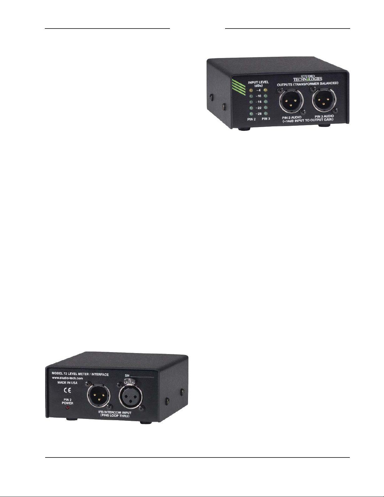
View showing IFB/intercom input and power present
LED indicator
View showing level meters and audio outputs
IFB or intercom audio signals to be combined and/or routed to other local or remote
talent or production personnel cue systems.
Other applications may arise where an amplified speaker needs to be used to monitor
an IFB or intercom circuit. The Model 72’s
audio outputs will make achieving this fast
and simple.
Power for the Model 72 is provided by the
connected IFB or intercom circuit. Active circuitry ensures accurate level metering and
excellent audio performance. The compact
device is housed in a rugged aluminum
enclosure. All inputs and outputs interface
using industry-standard 3-pin male and female XLR-type connectors. The connectors
are manufactured by Neutrik® and feature
gold-plated contacts and metal housings.
The Model 72 is compatible with virtually
all single- and dual-channel IFB and intercom circuits used in broadcast, theatrical,
and industrial applications. IFB circuits,
typically provided by Studio Technologies’
IFB interface units or the RTS® 4000-series,
can be directly connected. Industrystandard party-line intercom circuits are
also compatible. Whether a single-channel
system from Clear-Com® or a dual-channel
TW-series system from RTS, direct connection to the Model 72 is supported.
Model 72 User Guide Issue 2, July 2004
Studio Technologies, Inc. Page 3
Page 4

Model 72
Level Meter / Interface
The Model 72 provides both 3-pin male
and female XLR-type connectors for
direct interconnection with IFB and intercom circuits. The connector’s pins are
wired in parallel, allowing compatibility
with interconnecting cables having male
or female connectors. The two connectors
can also serve as a “loop through” function. Pin 1 of the connectors is used as
a common point for both DC power and
audio signals. Pin 2 of the connectors is
always used for DC power, typically in
the range of 25 to 30 volts. With dualchannel IFB or intercom circuits pin 2 is
also used to carry one of the two audio
signals, typically designated as channel 1.
(This audio signal is superimposed onto
the DC voltage.) Pin 3 is always used to
carry an audio signal but never DC power.
In dual-channel IFB or intercom systems
pin 3 typically carries channel 2 audio.
In single-channel intercom systems pin 3
carries the one and only audio signal.
The Model 72 was developed out of
necessity, once again proving that the old
saying is correct; necessity was definitely
the “mother” when it came to the unit’s invention. The genesis was very simple. Often when testing audio equipment out “in
the field,” Studio Technologies personnel
felt “blind” when interfacing with IFB and
intercom circuits. Typically it was difficult
to obtain “clean” balanced line-level audio
signals, and never possible with a nominal level approaching +4 dBu. Worse yet,
confirming the signal levels of an IFB or
intercom circuit was virtually impossible.
It often seemed that the signal levels were
either too low or too “hot,” but there was
no simple way available to establish that
fact. With the Model 72 these problems
should disappear. Monitoring of the audio
levels is clear and accurate, and balanced
line-level outputs are directly available.
Operation
The only action required for initial operation of the Model 72 is connecting an IFB
or intercom circuit. If the audio outputs are
going to be utilized interconnecting cables
must also be connected. No external
power source is necessary and the unit
contains no configuration switches or user
controls.
Connecting an IFB or
Intercom Circuit
Two 3-pin XLR-type connectors, one male
and one female, are associated with the
Model 72’s IFB/intercom input. The three
pins on each connector are wired in parallel, allowing the mating connector on
the interconnecting cable to be of either
gender. In addition to providing interfacing
flexibility, the two connectors can be used
in a loop-through arrangement. This may
eliminate the need in some applications
to use a “Y” or splitter cable.
The connected IFB or intercom circuit
must have common on pin 1, DC power
(and possibly audio) on pin 2, and audio
on pin 3. For correct Model 72 operation
the DC power on pin 2 must be within
the range of 22 to 32 volts and capable
of supplying 42 milliamperes of current.
Once an IFB or intercom circuit is connected the red LED, labeled PIN 2 POWER,
should light.
Level Meters
Any time that an IFB or intercom circuit
is connected to the Model 72 the two
5-segment LED meters will be active.
Issue 2, July 2004 Model 72 User Guide
Page 4 Studio Technologies, Inc.
Page 5

Model 72
Level Meter / Interface
They display the level of audio signals
present on pins 2 and 3 of the connected
circuit. The meters are calibrated to clearly
display the signal levels found on typical IFB and intercom circuits. The meters
display the actual signal levels that are
present on the pins in dBu. (This relates to
the voltage level, in dB, as referenced to
0.775 volts RMS.) The ballistics of the meter is a cross between that of a VU and a
peak (PPM) meter. (We affectionately refer
to it as a “PU” meter!) The way the LEDs
“move” in response to signals should be
comfortable for most users to observe.
Green LEDs are used to display the meters’ lowest four level steps. They light
to indicate signal levels that are typically
present on a correctly functioning IFB or
intercom circuit. The LED that displays
the highest value on the meter scale
(–4 dBu) is yellow in color, indicating that
a relatively “hot” signal is present. While
not necessarily a problem, having the
yellow LED lighting steadily would typically indicate a signal level that may be of
concern.
Audio Outputs
Two transformer-balanced line-level audio
outputs are provided. One output is associated with the audio signal that may
be present on pin 2 of the connected IFB
or intercom circuit. The other output is
associated with the audio signal that is
present on pin 3 of the connected circuit.
Whether signal is available on both audio
outputs will depend on the type of IFB or
intercom circuit that is connected. The
actual level on the audio outputs is 14 dB
above its source, i.e., there is 14 dB of
input-to-output gain. This was selected so
that connecting a typical IFB or intercom
circuit that has a nominal level of –10 dBu
will result in a +4 dBu nominal level on the
audio output connectors.
Each audio output is connected to external devices using a 3-pin male XLR-type
connector. Mating connectors (females)
should be prepared so that signal high
(+ or hot) is on pin 2 and signal low (– or
cold) is on pin 3. The cable’s shield can
be connected to pin 1, but it will have no
function. To limit the chance of grounding interaction between the Model 72 and
connected equipment, the pin 1 connections on both audio output connectors are
isolated from any point in the Model 72.
The fact that pin 1 “floats” will minimize
the chance of hums, noise, or buzzes being present on the equipment connected
to the main output.
For full electrical isolation, the audio outputs are transformer isolated. To provide
protection against accidental connection to cables that have DC power present, the audio outputs are also capacitor
coupled. In series with the output leads
are 300 ohm resistors, making the effective output impedance 600 ohms. These
resistors serve several purposes. They
will limit the maximum amount of output
current that can be drawn in the event of a
cable short. In addition, they allow multiple
audio outputs to be connected together,
creating a passive summing network. By
using a simple “Y” cable the two audio
outputs can be passively summed. A side
effect from using this passive summing
technique is that signal attenuation will occur. The audio quality won’t suffer, but this
passive summing method does create an
audio “pad.” If the two audio outputs are
connected together a signal attenuation
of 6 dB can be expected.
Model 72 User Guide Issue 2, July 2004
Studio Technologies, Inc. Page 5
Page 6

Model 72
Level Meter / Interface
Technical Notes
Channel Assignments
By design, the Model 72 doesn’t define
what signals will be present on the pins
of the connected IFB or intercom circuit.
This is because of the many different ways
signals and signal names can be assigned
to the same type of circuit. For universality, the meters and audio outputs are
referenced to the pins on the IFB/intercom
input, rather than having assigned names.
This naming method leads to one level
meter and one audio output being associated with pin 2. The second meter and
audio output is associated with pin 3. For
reference it may be worthwhile to list some
standard pin assignments:
• In broadcast IFB applications pin 2 is
often defined as the “interrupt” or the
“program-with-interrupt” channel. It
may also be referred to as IFB channel
1. Pin 3 is often defined as “program”
or “program-only.” It may also be referred to as IFB channel 2.
• Many broadcast applications use
TW-type intercom systems from RTS.
In these cases pin 2 will be intercom
channel 1; pin 3 will be intercom
channel 2.
• Often theatrical and industrial applications use single-channel intercom systems from Clear-Com. In these cases
pin 2 will only provide DC power, having no audio source associated with
it. Pin 3 will provide intercom audio or
intercom channel 1.
Power LED and Input Voltage
It’s important to note that the LED labeled
PIN 2 POWER will light essentially any
time a positive DC voltage is present on
pin 2 of either of the IFB/intercom input
connectors. Any DC that’s above approximately 3 volts is sufficient to light the LED.
This is by design as the LED is really just
intended to indicate that a “wet” circuit
has been connected. For full Model 72
operation the DC input needs to be in the
range of 20 to 22 volts.
IFB Audio Levels
The nominal level of audio signals associated with IFB circuits is typically –10 dBu.
This is the case with the interface units
from Studio Technologies, as well as such
systems as the RTS 4000-series. But actually having the correct level present
on an IFB circuit is often a “hit-or-miss”
proposition. During field testing Studio
Technologies’ personnel found that a
wide range of nominal audio levels were
present on “real-world” IFB circuits. Many
were fine, being reasonably close to the
desired –10 dBu. But some were much too
low, while others were much too “hot.” We
observed one unfortunate baseball “color”
commentator being sent interrupt audio
signals so “hot” relative to program audio
as to almost make his ears bleed! This
situation should not have been allowed
to happen.
In defense of field technical personnel,
measuring the audio level of an IFB circuit
hasn’t traditionally been an easy proposition. But that situation has now changed
with the Model 72. Using the unit will allow
level controls on the source equipment to
be adjusted as required.
Issue 2, July 2004 Model 72 User Guide
Page 6 Studio Technologies, Inc.
Page 7

Model 72
Level Meter / Interface
Intercom Audio Levels
In North America the two most common
intercom systems are those from RTS
and Clear-Com. From tests performed
in Studio Technologies’ lab the nominal
RTS TW-series audio level was approximately –10 dBu. The dynamic range
control provided by belt-packs such as
the MP-325 was very good, limiting the
maximum level to at most 10 dB above
the nominal. The nominal audio level associated with a single-channel Clear-Com
system was harder to characterize. It appeared to be a few dB less than –10 dBu,
but with a much larger dynamic range.
Level peaks of 10 to 20 dB over nominal
were easy to produce.
The contents of this section, along with the
previous one, may elicit howls of protest
from a host of engineers and intercomsystem experts. But for years we’ve heard
differing reports as to the actual nominal
audio levels for RTS and Clear-Com
systems. The “in-the-know cats” agreed
that the nominal level of RTS TW-series
intercom (and 4000-series IFB) was
–10 dBu, a value that we confirmed in our
tests. But the nominal level for Clear-Com
party-line systems was variously reported
as –20, –15, –12, –10, and “you know,
the Clear-Com level!” It’s most likely that
early Clear-Com systems did use a nominal level in the –20 dB range. But after
making controlled tests, their contemporary equipment seemed to be much
closer to –10 dBu. And with the limited
dynamic-range control that we experienced, the actual level during operation
may vary widely.
In conclusion, the engineers at Studio
Technologies are always open to learning
more. Additional information from the field
concerning IFB and intercom system levels would be welcomed. Stopping by our
offices for an in-person chat would be also
great. (And bringing along pizza and beer
for a tech-talk session would certainly get
our attention!) Just park the production
trailers on the street!
Model 72 User Guide Issue 2, July 2004
Studio Technologies, Inc. Page 7
Page 8

Model 72
Level Meter / Interface
Specifications
General Audio:
Frequency Response: 20 Hz-20 kHZ, ±0.5 dB
Distortion (THD+N): 0.02%, measured at 1 kHz,
–10 dBu in/+4 dBu out
S/N Ratio: 93 dB, referenced to –10 dBu in/
+4 dBu out
Connectors:
IFB/Intercom Input: 3-pin male and female
XLR-type
Audio Outputs: 3-pin male XLR-type
IFB/Intercom Input:
Type : single- or dual-channel, unbalanced (pin 1
common; pin 2 DC (or DC with audio); pin 3 audio)
Impedance: 20 k ohms, nominal
Level: –10 dBu, nominal
Compatibility: virtually all single- and dual-channel
IFB and intercom circuits
Audio Outputs:
Type : balanced, transformer-coupled with series
capacitors and isolation resistors
Impedance: 600 ohms, nominal
Nominal Level: +4 dBu, measured with –10 dBu
IFB/intercom input level
Maximum Level: +16 dBu into 2 k ohms
Gain: 14 dB, input-to-output
Power Requirement:
22-32 Vdc, 42 mA (provided by IFB/intercom input)
Dimensions (Overall):
4.2 inches wide (10.7 cm)
2.0 inches high (5.1 cm)
4.7 inches deep (11.9 cm)
Weight: 0.8 pounds (0.35 kg)
Specifications and information contained in this
User Guide subject to change without notice.
Issue 2, July 2004 Model 72 User Guide
Page 8 Studio Technologies, Inc.
Page 9

 Loading...