

Page 1

for Surround
Model 65 Bass Manager
User Guide
Issue 4, January 2004
This User Guide is applicable for serial numbers:
M65-00151 and later
Copyright © 2004 by Studio Technologies, Inc., all rights reserved
5520 West Touhy Avenue
Skokie, Illinois 60077 U.S.A.
Telephone (847) 676-9177
Fax (847) 982-0747
www.studio-tech.com
support@studio-tech.com
50087-0104, Issue 4
Page 2

Page 3

for Surround
Table of Contents
Foreword ..................................................................... 5
Introduction................................................................... 7
Installation .................................................................... 10
Configuration ............................................................... 15
Operat i o n..................................................................... 23
Specifications .............................................................. 25
Block Diagram
Model 65 User Guide Issue 4, January 2004
Studio Technologies, Inc. Page 3
Page 4

for Surround
This page intentionally left blank.
Issue 4, January 2004 Model 65 User Guide
Page 4 Studio Technologies, Inc.
Page 5

for Surround
Foreword
I am pleased to present the Model 65 Bass Manager. As President of Studio Technologies,
I take a very personal approach when designing products. Growing older has increased
my appreciation of the more subtle things in life—be they a part of nature or the nuances
contained in a well-designed piece of electronic equipment. Do the technical and operational
aspects of a product work together to “feel” right? A Studio Technologies’ design is ready to
go only when I am completely satisfied.
Many fine people worked toward making the Model 65 “happen.” Mitch Budniak (ace consulting engineer) designed many of the circuits. Jim Cunningham contributed to the analog
design. Carrie Loving provided engineering support. Al Lux designed the printed circuit
board. Fred Roeck performed the mechanical design. Joe Urbanczyk coordinated the
product testing procedures.
Please contact me with your questions, comments, and suggestions. I can be
reached by voice at (847) 676-9177, fax at (847) 982-0747, or via e-mail by way
of support@studio-tech.com.
Sincerely,
Gordon K. Kapes
President
Model 65 User Guide Issue 4, January 2004
Studio Technologies, Inc. Page 5
Page 6

for Surround
This page intentionally left blank.
Issue 4, January 2004 Model 65 User Guide
Page 6 Studio Technologies, Inc.
Page 7

for Surround
Introduction
What This User Guide Covers
This User Guide is designed to assist you
when installing, configuring, and using the
Model 65 Bass Manager.
System Overview
Model 65 Bass Manager
The Model 65 Bass Manager is designed
to enhance the monitoring of multichannel
audio sources during the recording, mixing,
mastering, and distribution process. The
Model 65 is applicable for any multichannel
monitoring environment where some or
all channels are not supported with loudspeakers having extended low-frequency
response. Resources are included in the
Model 65 to make it appropriate for cinema,
music, and broadcast applications. The
Model 65’s design is oriented toward directly supporting 5.1-type applications. The
five main input channels are full bandwidth,
and use the industry-standard designation
of left, center, right, left surround, and right
surround. The “.1” input channel is designated as LFE, which is also referred to
as low-frequency effects, “boom,” or subwoofer. The LFE term originated in cinema
formats but is now part of music and broadcast formats as well.
The overall goal of the Model 65 is very
simple: Ensure that the entire audio bandwidth of all channels can be accurately
monitored. Many loudspeaker systems have
inherent low-frequency limitations, preventing a true picture of the source material from
being presented. To overcome this, the lowfrequency energy from the five main channels can be separated and routed to one or
two subwoofer loudspeakers. The Model 65
includes filters to accomplish this, providing
a smooth and sonically pleasing crossover
of the signals being routed to the main and
subwoofer loudspeakers.
The Model 65 also supports several
format-specific parameters required for
accurate LFE channel monitoring. To minimize digital bandwidth, some multichannel
formats restrict the frequency response of
the LFE channel. To emulate this process, a
low-pass filter can be inserted into the LFE
signal path. For compatibility with some
cinema formats, gain can also be added to
the LFE signal.
While the Model 65 is intended primarily for
use in 5.1 applications, additional specialized features and capabilities are also
included. These allow the unit to be configured to meet the needs of a broad range of
monitoring applications.
Main Inputs
The Model 65 contains five full-bandwidth
input channels, which are intended for
connection to left, center, right, left surround,
and right surround sources. The electronically balanced inputs are compatible with
balanced or unbalanced sources. Associated with each of the five main inputs is a
crossover circuit, created by means of
separate high- and low-pass filters. The
filters are factory-configured to provide a
nominal crossover frequency of 80Hz. The
output of each high-pass filter is routed to
the output circuit of its corresponding channel. The output of each low-pass filter can
be individually assigned to subwoofer output
1, subwoofer output 2, or subwoofer outputs
1 and 2. To prevent level build up, the signal
is attenuated 6dB when assigned to both
subwoofer outputs.
Model 65 User Guide Issue 4, January 2004
Studio Technologies, Inc. Page 7
Page 8
for Surround
LFE Input
The Model 65 contains an input channel that
is specifically intended for connection to an
LFE source. To simulate some multichannel
formats, a low-pass filter can be inserted,
using a front-panel switch or remote control
signal, into the LFE signal path. The filter,
created by cascading four 2nd-order SallenKey low-pass sections, provides a 48dBper-octave slope with the –6dB point at
120Hz.
To allow accurate monitoring of some
cinema formats, a front-panel switch allows
10dB of gain to be added to the LFE signal.
This ensures that the proper relative level is
maintained between the LFE signal and the
low-frequency energy derived from the five
main inputs. As with the main inputs, the
LFE signal can be assigned to subwoofer
output 1, subwoofer output 2, or subwoofer
outputs 1 and 2.
Outputs
The Model 65 provides five main and two
subwoofer outputs. Each of the outputs is
electronically balanced and can be connected to balanced or unbalanced loads. To
minimize the chance of loudspeaker damage, power up/power down mute relays are
associated with each output. The nominal
level of the five main outputs is +4dBu,
maintaining a unity gain input-to-output
relationship. The two subwoofer outputs are
handled somewhat differently, having a
nominal output level of –6dBu. This reduced
operating level allows sufficient audio headroom when phase coherent signals from the
main inputs are routed, by way of the lowpass filters, to the subwoofer outputs.
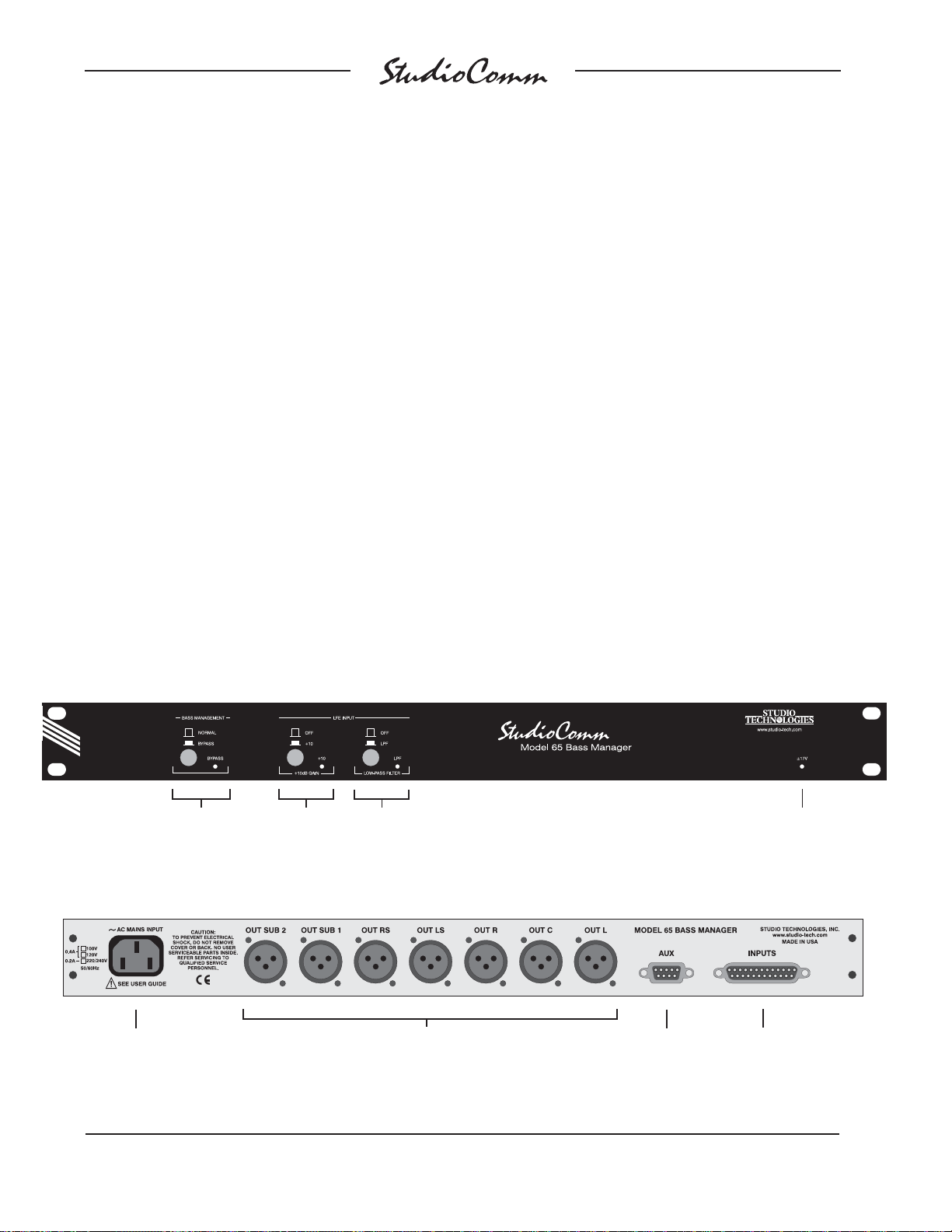
Model 65 Front Panel
Bass management
bypass function
Model 65 Back Panel
AC mains
connection
LFE +10dB
gain
LFE low-
pass filter
Main and subwoofer
output connections
Remote control
and expansion
connections
±17V LED
Main and LFE
audio input
connections
Issue 4, January 2004 Model 65 User Guide
Page 8 Studio Technologies, Inc.
Page 9

for Surround
Support for Two Subwoofers
As previously discussed, the outputs of
the low-pass filters associated with the
five main inputs, along with the LFE signal,
can be assigned to either or both of the
subwoofer outputs. The two subwoofer
outputs allow flexibility when designing a
loudspeaker system. A system could be
configured to support subwoofers that are
position-oriented, such as “sub left front”
and “sub right front.” Or, the subwoofers
could be configured according to program
content, such has having subwoofer output 1
handle only LFE information, while subwoofer output 2 handles the low-passed
signals from the main inputs.
Bass Management Bypass
A Model 65 feature allows the bass
management function to be disabled by
means of a front-panel switch. This function
can be useful, especially during the monitor
system installation and room-tuning process. When the bypass function is enabled,
the five main input signals route directly to
the main outputs. In addition, the outputs of
the low-pass filters associated with the main
inputs no longer route to either of the subwoofer outputs. However, when the bass
management bypass function is active the
LFE signal continues its normal routing,
flowing to either or both of the subwoofer
outputs.
Remote Control
Three remote control functions are available: LFE low-pass filter enable, LFE mute,
and subwoofer mono. The remote control
functions are specifically provided for use
during the recording or mixing process. An
effective installation could utilize foot
switches or console-mounted buttons to
allow easy operator access to the remote
control functions.
Remote control of the LFE low-pass filter
allows real-time confirmation of LFE content. Some release formats require that LFE
program content be band restricted. Under
this condition, a valid audio mix would have
no change in its sonic character when the
LFE low-pass filter is enabled.
When LFE mute is enabled, normal bass
management operation continues, but the
LFE signal is not routed to either of the
subwoofer outputs. This function allows
a direct check of the impact an LFE signal
is having on an overall mix.
The subwoofer mono function is provided to
allow confirmation of the phase-coherency
of the two subwoofer outputs. When the
function is enabled, the subwoofer signals
are combined (summed), attenuated by
6dB, and fed to both subwoofers.
Expansion Capability
Provision has been made to allow multiple
Model 65 units to be easily interconnected.
For example, by using two units, ten main
and two LFE inputs are supported, as well
as providing ten main and two subwoofer
output channels. For other special applications a virtually unlimited number of units can
be interconnected.
Flexibility
The Model 65 is designed to be used
directly “out of the box,” providing effective
bass management for most 5.1 applications. However, installation-specific requirements, along with the evolving world of
multichannel audio, make flexibility imperative. With the Model 65 you can use it “our
way,” or easily perform a minor or major
reconfiguration. A competent technician can
field-adjust a number of key bass management parameters.
Model 65 User Guide Issue 4, January 2004
Studio Technologies, Inc. Page 9
Page 10

for Surround
The high- and low-pass filters sections
associated with the main inputs are implemented by cascading two 2nd-order SallenKey filter circuits. Jumpers on the Model
65’s printed circuit board allow individual
selection of 12dB-per-octave or 24dB-peroctave response. The factory-default configuration for the high-pass filters is 12dB-peroctave, complementing the internal filters
contained in many amplified loudspeaker
systems. Other speaker systems may
benefit from the use of the 24dB-per-octave
setting. A third jumper position allows the
input signal to be directly routed to the
output. This “flat” selection supports loudspeaker systems that already contain filters
to provide the desired high-pass response.
As for the low-pass filters, the factory configuration is 24dB-per-octave, supporting the
needs of many subwoofer loudspeakers.
Alternately, the 12dB-per-octave settings
can be used to match the Model 65 with
other monitor systems.
The high- and low-pass filter frequencies
associated with the main inputs can be
individually adjusted. This allows the crossover frequencies to be configured on a
channel-by-channel basis. While the factory
default crossover frequency is set for nominally 80Hz, selecting an alternate crossover
frequency, symmetrical or asymmetrical, is
simple. To adjust any of these filters requires only changing resistors. Sockets are
present in the Model 65’s circuit board,
eliminating the need to solder.
The LFE low-pass filter frequency can also
be adjusted. The factory-default value is
120Hz, but can easily be revised.
Installation
In this section you will be installing the Model
65 Bass Manager in an equipment rack.
Audio input and output connections will be
made. If required, external equipment will be
interfaced to the remote control inputs. In
special applications, multiple Model 65s will
be interconnected. AC mains power will be
connected to the Model 65.
Prior to beginning the installation process,
a thorough review of the configuration
section is recommended. While it’s possible to use the Model 65 directly “out of the
box,” some configuration changes may add
significantly to the performance of a completed installation.
System Components
The shipping carton contains one each
of the following: Model 65 Bass Manager,
user guide, and warranty card. Units destined for North America also include an AC
mains cord. Your dealer or distributor will
provide an AC mains cord for non-North
American destinations.
Mounting the Model 65
The Model 65 requires one space in a
standard 19-inch (48.3cm) equipment rack.
It is desirable to locate the Model 65 to
allow access to both the front and the back
panels. The back panel contains the input
and output connectors. The front panel is
used to access several operator controls.
The Model 65 is secured to the equipment
rack using two mounting screws per side.
Issue 4, January 2004 Model 65 User Guide
Page 10 Studio Technologies, Inc.
Page 11

for Surround
Audio Inputs
The Model 65 provides six audio inputs: five
main and one LFE. These six channels are
designated L, C, R, LS, RS, and LFE.
Audio input signal connections are made by
way of a 25-pin D-sub connector located on
the Model 65’s back panel. One cable
harness, with a 25-pin D-sub plug (male)
on one end and the desired connector or
connectors on the other end, is required.
This cable harness is not supplied by Studio
Technologies. (Note that our friends in some
locations may use the term “loom” instead of
harness.)
The wiring scheme used by the input
D-sub complies with that made familiar by
TASCAM® with their DA-88® product.
A wiring harness prepared for connection
to the six audio input channels is identical to
that of a harness prepared to connect to the
first six channels of a DA-88 input harness.
Please refer to Figure 1 for the connection
details. Note that the Model 65’s D-sub
connector uses 4-40 threads.
Unless there’s a special need, it may be
cost and time effective to utilize a commercially made cable harness. Let the large
market for DA-88-style cabling help you
painlessly install your system!
Channel + – Shield
L 241225
C 102311
R21922
LS 7 20 8
RS 18 6 19
LFE 4 17 5
Notes: 1) Connector type on Model 65 is 25-pin
D-sub-miniature female. Installer must
provide plug (male). Connector uses 4-40
threaded inserts for locking with mating plug.
2) Wiring scheme follows Tascam DA-88
convention. Standard DA-88-type wiring
harnesses are directly compatible, with the
exception of 4-40 screw threads being required.
Figure 1. Main Audio Input Connections
wired so that signal high is connected to +
on the D-sub, signal low to – on the D-sub,
and shield to the D-sub’s shield connection.
With an unbalanced source connect signal
high to the + connection on the D-sub, and
shield to both the – and the shield connection on the D-sub. If connecting to an unbalanced source in this manner results in hum
or noise try connecting signal high to + on
the D-sub, and shield to – on the D-sub;
leave the shield connection on the D-sub
unterminated.
The Model 65’s input connector is directly
compatible with the monitor output connections of the Studio Technologies’ StudioComm for Surround Model 68 and Model
68A Central Controllers. The channel layout
arrangements of the two systems are identical, making interconnection simple.
Each input circuit is electronically balanced
and is intended for connection to balanced
or unbalanced sources with a nominal signal
level of +4dBu. Balanced sources should be
Model 65 User Guide Issue 4, January 2004
Studio Technologies, Inc. Page 11
Audio Outputs
The Model 65 provides seven audio outputs, designated L, C, R, LS, RS, Sub 1,
and Sub 2. These outputs are intended
for connection to audio amplifiers associated with monitor loudspeakers, or to the
inputs of loudspeakers with integrated
amplifiers. The outputs are electronically
balanced and capable of driving balanced
or unbalanced loads of 600 ohm or greater.
Page 12

for Surround
The nominal output level of the main channels, L, C, R, LS, and RS, is +4dBu. The
nominal output level of Sub 1 and Sub 2 is
–6dBu.
Seven 3-pin male XLR-type connectors
are used to interface with the Model 65’s
outputs. Prepare the mating connectors
(females) so that pin 2 is signal + (high or
hot), pin 3 is – (low or cold), and pin 1 is
shield. To connect to an unbalanced load
connect pin 2 as signal + (high or hot) and
pins 1 and 3 as signal low/shield. For optimal unbalanced operation, it is important to
connect pins 1 and 3 together directly on the
connector that mates with the Model 65 and
not on the other end of the cable.
Note that while the Model 65’s electronically
balanced output circuits are capable of
driving loads of 600 ohms or greater the
output level will drop slightly as the load
impedance approaches 600 ohms. For
example, a 0.5dB difference in output level
can be expected as the load impedance
changes from 10k ohms to 600 ohms.
Remote Control Functions
Support is provided for three remote control
functions: LFE low-pass filter enable, LFE
mute enable, and subwoofer mono enable.
The three inputs use logic gates, “pulled up”
to +5V by way of resistors, which are active
when brought to the logic low state. Inputs of
this type are commonly referred to as GPI
inputs. While the input circuitry is protected
from over-current and static (ESD) discharge care should be taken to prevent
nasty signals from reaching them. The
inputs are active only when held in the low
state; they can’t be configured to change
state (“latch”) in response to a logic pulse.
The 9-pin D-sub connector (labeled AUX
on the back panel) is used to interface the
three remote control inputs. Refer to Figure
2 for connection details. Note that pin 1
(shield/remote common) and pin 9 (audio
common) are electrically identical. In addition to connecting to system common they
connect to the Model 65’s chassis and
mains earth connections. Even so, the
shield of the interconnecting cable, along
with the remote control source’s common
signal, should be connected to pin 1 (shield/
remote common). Pin 9 (audio common)
should be reserved for use when interconnecting the audio signals of multiple Model
65 units.
Pin Signal
1 Shield/Remote Common
2 LFE Low-Pass Filter Enable
3 LFE Mute Enable
4 Subwoofer Mono Enable
7 Audio Link Sub 1
8 Audio Link Sub 2
9 Audio Common
Notes: 1) Connector type on Model 65 is 9-pin
D-subminiature female. Connector uses 4-40
threaded inserts for locking with mating plug.
Figure 2. Aux Connector Pin Out for Remote
Control and Expansion Functions
Interconnecting Multiple Units
Expansion capability is an integral part of
the Model 65’s design. A virtually unlimited
number of units can be connected together
to provide bass management for a variety
of applications. For example: bass management may be needed for an experimental
10.2 playback system. This can be easily
created by using two Models 65, along with
a simple interface cable.
Issue 4, January 2004 Model 65 User Guide
Page 12 Studio Technologies, Inc.
Page 13

for Surround
It’s important to understand how multiple
units operate together before attempting an
implementation. The Model 65 functions that
are interconnected are the remote control
inputs and the subwoofer outputs. The
remote control functions are pretty obvious
as to why they need to be interconnected. A
user will want a single command to enable
the identical remote control functions on all
Model 65 units. The remote control input
circuitry was specifically designed to allow
multiple units to be directly connected
(bridged) together.
Using multiple Model 65 units is a little more
involved when it comes to the subwoofer
outputs. Each Model 65 has five main inputs
with directly associated outputs: L, C, R, LS,
and RS. Each of them can also assign bass
management audio information to Sub 1,
Sub 2, or both. In addition to the five inputs,
a sixth input, LFE, can also be routed to Sub
1, Sub 2, or both. But when multiple Model
65s are used, the bass management and
LFE input information from all units must
end up on a common set of Sub 1 and Sub
2 outputs. This is accomplished by designating one Model 65 as “master” and using
its Sub 1 and Sub 2 outputs as the connections to the subwoofer loudspeakers. The
other Model 65 units are configured as
“slaves” and send bass management and
LFE audio information to the master unit. In
practice, the hardware linking is accomplished using three pins on the Model 65’s
Aux connector. The three pins link the units
together in a simple one-to-one connection
arrangement. In addition, two internal jumpers must be configured on each unit.
The installation of multiple Model 65 units
begins by configuring one unit to serve as
“master” and the other unit(s) as “slave.”
Internal jumper, located on the Model 65’s
circuit board, allow each unit to be configured for either mode, or to the factoryconfigured disabled mode.
Warning: A competent technician
is required to perform any configuration
review or changes. The cover of the
Model 65 must be removed to access
the configuration jumpers. This exposes
the technician to a potential shock
hazard. Only after mains power has
been disconnected and the mains cord
removed from the back of the Model 65,
should the cover be removed.
Once mains power has been disconnected,
the cover of each Model 65 can be removed. Option jumpers are associated with
the expansion functions. These are located
on the printed circuit board. Refer to Figure
3 for detailed view. From the factory the
jumpers for audio link Sub 1 and audio link
Sub 2 are set to the disabled position. On
the Model 65 designated as “master,” the
jumpers must be moved to the positions
labeled IN. This configures the unit to receive sub audio from the slave(s). On the
Model 65 unit(s) designated as “slave,” the
jumpers must be moved to the positions
labeled OUT. This configures the unit(s) to
send bass management and LFE information to the master. Confirm that the desired
configuration has been achieved. The
covers from the Model 65 units can then be
replaced and secured.
Implementing the physical connections
between multiple units is simple. First of all,
the Model 65 units should be mounted in
adjacent rack spaces. This will encourage
Model 65 User Guide Issue 4, January 2004
Studio Technologies, Inc. Page 13
Page 14

for Surround
Figure 3. Link Signal Configuration
creating the shortest possible interconnecting cables. Should the remote control inputs
be utilized, they must be interconnected by
way of pins in the Aux connector. Refer to
Figure 2 for a detailed description of the
connections on the 9-pin D-sub Aux connector. Pin 1 (Shield/Remote Common), pin 2
(LFE Low-Pass Filter Enable), pin 3 (LFE
Mute Enable), and pin 4 (Subwoofer Mono
Enable) on all Model 65 units must be
connected together in a one-to-one arrangement. While not required, using shielded
cable is optimal with pin 1 connecting to
shield.
The bass management and LFE audio
signals on multiple units are connected
together using pins 7 (audio link Sub 1),
8 (audio link Sub 2) and 9 (audio common).
They, too, should be connected in a one-toone arrangement. As the audio signals are
unbalanced shielded cable is optimal with
pin 9 being connected to the shield. Be
certain to keep the interconnecting cable
length to a minimum.
AC Mains Power
The Model 65 is internally configured to
operate from either 100, 120, or 220/240V,
50/60Hz. In most cases, units shipped to
North America are factory selected for
120V operation. Units bound for Japan may
have been selected for 100 or 120V, while
our friends “down under” and in Europe
receive units set for 220/240V. Before
connecting the Model 65 to AC mains
power check that it is configured to match
the local mains voltage. Look on the back
panel, adjacent to the power entry connector
for the configured voltage. Note that an
incorrect configuration could seriously
damage the unit. Should it be necessary to
change the unit’s operating voltage it must
be performed only at the factory or by a
competent service technician.
The Model 65 uses an IEC standard connector to mate with the AC mains cord. The
wire colors in the AC mains cord should
conform to the internationally recognized
CEE color code and must
be wired accordingly:
Connection Wire Color
Neutral (N) Light Blue
Line (L) Brown
Protective Earth (E) Green/Yellow
Issue 4, January 2004 Model 65 User Guide
Page 14 Studio Technologies, Inc.
Page 15

for Surround
Safety Warning: The Model 65 does
not contain an AC mains disconnect
switch. As such, the mains cord plug
serves as the disconnection device.
Safety consideration requires that the
plug and associated outlet be easily
accessible to allow rapid disconnection of mains power should it prove
necessary.
After mains power has been connected, a
power-up delay circuit prevents operation
for several seconds. This delay prevents
audio “pops” or other noise from being
sent out the main audio outputs and on to
the loudspeakers. Once the power-up delay
has elapsed, the Model 65’s power present
LED will light and the output muting relays
will change to their normal non-muted state.
The unit is now ready for years of trusty
service!
Configuration
The configurable parameters can be separated into two groups: basic and advanced.
The basic parameters are high- pass filter
slope selection, low-pass filter slope selection, and subwoofer assignment. The
advanced parameters are high- and lowpass filter frequency adjustment, as well
as adjustment of the LFE low-pass filter
frequency.
Warning: Mains power must be
disconnected prior to setting the
mode. Only a competent technician
must perform this procedure!
Basic Configuration
In this section the configuration of the main
input’s high- and low-pass filter slope will
be reviewed. Changes will be made if
necessary to meet the needs of the monitor
system. The bass management and LFE
signal routing to the subwoofer outputs will
be reviewed. Again, changes will be made
if required.
While it is easy to install and use, the Model
65 does provide a number of configurable
parameters that can be used to “tune” an
installation for optimum performance.
From the factory, default settings have
been selected that are appropriate for many
installations. But don’t be lulled into complacency by the fact that “out of the box” the
Model 65 may seemingly perform well in
an application. It’s critical to review how the
Model 65 functions within the scope of the
entire monitoring system. A system will only
meet its potential when all of the components work together to achieve a
common goal.
Model 65 User Guide Issue 4, January 2004
Studio Technologies, Inc. Page 15
High-Pass Filter Slope Selection
Each of the five main input channels (L, C,
R, LS, and RS) includes a high-pass filter
section. These filter sections remove the
audio-frequency content that is to be routed,
by way of the low-pass filters, to the subwoofer output(s). Each filter section is
implemented by cascading (connecting in
series) two identical high-pass filter circuits.
Each filter circuit has a slope of 12dB-peroctave and is factory selected to have its
–3dB point at nominally 80Hz. Option jumpers are provided to allow the audio signal
to pass through either or both of the filters,
providing a slope of 12- or 24dB-peroctave. For added flexibility, an additional
jumper position allows the filter to be
Page 16

for Surround
removed from the signal path. This is designated as the Flat position. Refer to Figure 4
for a detailed view of the jumper locations.
From the factory the jumper locations are
configured for 12dB-per-octave. This is
appropriate for many applications, such
as where the loudspeakers connected to
the main-channel outputs include a 12dBper-octave high-pass filter. (Of course this
assumes that an overall 24dB-per-octave
response is desired.) Many small amplified
loudspeakers include such internal highpass filters. There are also situations where
the 24dB-per-octave setting would be the
correct choice. This would be the case
where the loudspeakers connected to the
main-channel outputs do not contain integral
high-pass filters.
The Flat position is provided for special
situations. An example would be where the
loudspeakers associated with the main
channels already implement the desired
low-frequency response curve. This could
be due to the loudspeakers containing
integral high-pass filters, or to the fact
that the speaker’s inherent low-frequency
response naturally provides the desired
frequency response. To review: In the Flat
position the full bandwidth of the signals
entering the main inputs (L, C, R, LS, and
RS) route directly to their respective output
circuitry. No high-pass filtering is performed.
The key to correctly selecting the slope of
the high-pass filters is to first understand the
needs of the entire monitoring system. It’s
important to maintain a smooth transition
Figure 4. High-Pass Filter Slope Selection
Issue 4, January 2004 Model 65 User Guide
Page 16 Studio Technologies, Inc.
Page 17

for Surround
(crossover) between the main channel
loudspeakers and the bass management
audio signals being reproduced by the
subwoofer(s). Only by studying the entire
monitoring configuration can a correct
selection be made. Personal taste and
philosophy play a major role in decisions
like these. Some people prefer crossover
slopes of 24dB-per-octave, while others
prefer the more gentle 12dB-per-octave.
Don’t minimize the impact that a little planning can have on a system’s performance.
Low-Pass Filter Slope Selection
Each of the five main input channels (L, C,
R, LS, and RS) includes a low-pass filter
section. These filter sections separate the
audio-frequency content that will be routed
to either or both of the subwoofer outputs.
Each filter section is implemented by cascading (connecting is series) two identical
filter circuits. Each filter circuit has a slope
of 12dB-per-octave and is factory selected
to have its –3dB point at nominally 80Hz.
Option jumpers are provided to allow the
slope of the signal going to the subwoofers
to be 12- or 24dB-per-octave. Refer to
Figure 5 for a detailed view of the jumper
locations.
From the factory the jumper locations are
configured for 24dB-per-octave. This is
appropriate for applications where a relatively steep crossover slope is desired.
There are situations where selecting the
12dB-per-octave setting may be appropriate. Specific examples are hard to provide
as the number of different monitoring
Figure 5. Low-Pass Filter Slope Selection
Model 65 User Guide Issue 4, January 2004
Studio Technologies, Inc. Page 17
Page 18

for Surround
arrangements is enormous. The key to
successful selection is to ensure that the
low-pass filter slope meets the exact needs
of the monitoring system.
Subwoofer Assignment
Each of the five main input channels (L, C,
R, LS, and RS) includes a low-pass filter
section. The output of these filters is the
“bass management” signal that is routed to
either or both of the subwoofer output channels. The LFE input channel is also routed
to either or both of the subwoofer outputs.
Option jumpers, located on the printed
circuit board, allow selection of the desired
routing. Refer to Figure 6 for a detailed view
of the jumper locations. The choices are
Sub 1, Sub 2, or both Sub 1 and 2. An
attenuation (level drop) of 6dB is implemented whenever the routing is selected for
both Sub 1 and Sub 2. This feature is important, preventing low-frequency level buildup.
From the factory the subwoofer routing
for the five main inputs and the LFE input
is selected to be Sub 1. This is appropriate
for applications where a single subwoofer
loudspeaker will be utilized. The jumpers
can easily be changed to support an alternate configuration. There are many opinions
as to how subwoofers should be used in a
listening environment—almost as many as
there are opinions as how to correctly make
a martini! In some cases, two sub-woofers
might be used in a “stereo” configuration.
One may be designated as sub left, the
other as sub right. In this case, main input L
and LS signals might be assigned to Sub 1,
R and RS would be assigned to Sub 2,
while C and LFE would be assigned to both
sub outputs. Another application might find
one subwoofer used for the main input
channels and the second for the LFE channel. In this case L, C, R, LS, and RS would
be assigned to Sub 1, while LFE would be
assigned to Sub 2.
Figure 6. Subwoofer Assignment
Issue 4, January 2004 Model 65 User Guide
Page 18 Studio Technologies, Inc.
Page 19

for Surround
There might be a case where it is desirable
to have one of the five main inputs not
assigned to a subwoofer output. While we
can’t really think of an application like this,
there is no technical problem in having no
routing selected for a main input channel.
Leaving jumper positions unused should not
pose a problem.
Advanced Configuration
In this section the configuration of the main
input’s high- and low-pass filter frequencies
will be reviewed. Changes will be made if
necessary to meet the needs of the monitor
system. The frequency of the low-pass filter
associated with the LFE input will be
reviewed. Again, changes will be made
if required.
Main Input High-Pass Filters
As previously discussed, each of the five
main input channels (L, C, R, LS, and RS)
has a high-pass filter section associated
with it. Each filter section is created by
cascading (connecting in series) two identical 2nd-order Sallen-Key filter circuits. Components were selected at the factory so that
the filter section’s output has a –6dB point
of nominally 80Hz. (To be more precise, the
math calculations work out to be 83Hz.) For
some applications it may be optimal to
adjust this frequency. The Model 65 makes
this a simple task, with no soldering or
complicated procedure required. Note that
each of the five high-pass filter sections can
be independently configured. This is provided to meet “real world” monitoring environments. For example, it’s quite reasonable that the L, C, and R channels utilize one
frequency, while the LS and RS channels
use another.
The frequency of each filter section is configured by means of six resistors, each
identical in value. Two 6-position sockets,
located on the printed circuit board, are
used to hold the resistors. As received from
the factory, two 27k (27,000) ohm 6-pin
single-inline-package (SIP) resistors are
used to configure the filters for nominally
80Hz. To revise the frequency these can be
replaced with two 6-pin SIP resistors, or six
individual ¼-watt, 1%-tolerance resistors.
The SIP resistors must be isolated-terminaltype, providing three independent resistors
in one assembly. As the SIP resistors have
a tolerance of 2%, using ¼-watt 1%-tolerance, rather than 5%-tolerance, resistors is
appropriate.
A simple formula is used determine the
resistance required for a specific filter
frequency: R = 2,251,000 ÷ F, where R
is resistance in ohms and F is frequency
in hertz. Figure 7 lists several frequencies
that are provided by standard SIP resistors.
Using ¼-watt, 1%-tolerance resistors will
allow many other frequencies to be implemented.
Once the new SIP or 1%-tolerance resistors
have been procured, they should be doublechecked. Use an ohmmeter to confirm that
the resistance value is correct. If SIP resistors are being used, check to ensure that
they are isolated-terminal-type. These
simple checks should take only a short time
and will insure that a change to the filters will
achieve the desired audio performance.
150Hz: 15k 68Hz: 33k
125Hz: 18k 58Hz: 39k
113Hz: 20k 48Hz: 47k
102Hz: 22k 40Hz: 56k
83Hz: 27k 33Hz: 68k
Figure 7. High-Pass Filters, Frequency versus
SIP Resistor Value
Model 65 User Guide Issue 4, January 2004
Studio Technologies, Inc. Page 19
Page 20

for Surround
The process required to actually change the
components is simple, although a competent technician must perform the steps.
Following the previously discussed safety
procedures, mains power must be disconnected and the Model 65’s cover removed.
Refer to Figure 8 for a detailed description
of the location of the resistors on the printed
circuit board. The factory-installed 27k SIP
resistors must be carefully removed by
using a pair of needle-nosed pliers. The SIP
resistors should be lifted straight up out of
their sockets. If SIP resistors are to be used
to achieve the revised frequency, they can
be directly inserted into the sockets. Pin 1 of
the SIP resistors should correspond with pin
1 of the sockets. Pin 1 is clearly marked by
means of a white dot on the printed circuit
board.
If six individual 1%-tolerance resistors are
to be used they must first be prepared for
insertion. To begin, one lead of each of the
resistors must be folded over (carefully bent
180 degrees) so that it becomes parallel
with the other. Then both leads must be
trimmed (cut) so that they extend out from
the body of the resistor by about 1/8 to 1/4
inch. Once this has been completed the
resistors can be inserted into the sockets,
with three going into each. The first resistor
is inserted into socket pins 1 and 2, the
second into pins 3 and 4, and the third into
pins 5 and 6. After the resistors are inserted, ensure that they are positioned so
that they stand straight up, safely away from
other components.
Figure 8. Main Input High-Pass Filter Frequency Configuration
Issue 4, January 2004 Model 65 User Guide
Page 20 Studio Technologies, Inc.
Page 21

for Surround
Main Input Low-Pass Filters
Each of the five main input channels (L, C,
R, LS, and RS) also has a low-pass filter
section associated with it. Each filter section is made up of two identical filter circuits
that are cascaded, i.e., connected in series.
Components were selected at the factory so
that the filter section’s output has a –6dB
point of nominally 80Hz. (To be more precise, the math calculations work out to be
82Hz.) As with the high-pass filter sections,
each of the five low-pass filter sections can
be configured independently. It’s quite
reasonable that the L, C, and R channels
utilize one frequency while the LS and RS
channels use another. It’s also reasonable
that each input channel’s low-pass frequency be configured differently from its
associated high-pass filter frequency. Using
asymmetrical filter settings can be very
effective in achieving the desired monitor
system performance.
that are created using 1%-tolerance and
SIP resistors. As may be evident, the frequencies were selected to roughly match
the high-pass filter frequencies shown in
Figure 7.
150Hz: 7.50k 68Hz: 16.5k
124Hz: 9.09k 57Hz: 19.6k
113Hz: 10.0k 48Hz: 23.7k
102Hz: 11.0k 40Hz: 28.0k
82Hz: 13.7k 33Hz: 34.0k
Figure 9. Low-Pass Filters, Frequency versus
1%-Tolerance Resistor Value
As with the procedure for the high-pass
filters, once new 1%-tolerance or SIP
resistors have been procured, they should
be double-checked. Use an ohmmeter to
confirm that the resistance value is correct.
If a SIP resistor is being used, check that it
is an isolated-terminal-type.
The frequency of each low-pass filter section is configured by means of four ¼-watt,
1%-tolerance resistors, each identical in
value. One 8-pin socket, located on the
printed circuit board, is used to hold the
resistors. From the factory, four 13.7k
(13,700) ohm resistors are used to configure the filters for nominally 80Hz. To revise
the frequency, these can be replaced with
four other resistors, or one 8-pin SIP resistor package. It’s important to note that the
SIP resistor must be isolated-terminal-type,
providing four independent resistors in one
assembly.
A simple formula is used determine the
resistance required for a specific filter
frequency: R = 1,125,400 ÷ F, where R
is resistance in ohms and F is frequency
in hertz. Figure 9 lists several frequencies
The process required to actually change the
resistors is basically the same as with the
high-pass filter sections. Refer to Figure 10
for a detailed description of the location of
the resistors on the printed circuit board.
The four factory-installed 13.7k resistors
should be carefully removed by using a pair
of needle- nosed pliers. If four individual
resistors are to be used, they must be
prepared for insertion. The first resistor is
inserted into socket pins 1 and 2, the second into pins 3 and 4, etc. After the resistors
are inserted, ensure that they are positioned
so that they stand straight up, safely away
from other components.
LFE Input Low-Pass Filter
A low-pass filter section is associated with
the LFE input channel. This 48dB-peroctave filter can be inserted into the LFE
Model 65 User Guide Issue 4, January 2004
Studio Technologies, Inc. Page 21
Page 22

for Surround
Figure 10. Main Input Low-Pass Filter Frequency Configuration
signal path to simulate the bandwidth
restrictions found with some digital audio
distribution formats. The low-pass filter
section is made up of four 2nd-order SallenKey filter circuits that are cascaded, i.e.,
connected in series. Components were
selected at the factory so that the filter
section’s output has its –6dB point at nominally 120Hz. For some applications it may
be desirable to revise the frequency of the
low-pass filter. For example, in the future
it’s possible that the –6dB point may need
to be configured for 80Hz, matching the LFE
encoding parameters as proposed by the
creators of several formats.
As received from the factory two 8-pin SIP
located on the printed circuit board are used
to hold the resistors. To achieve the 120Hz
frequency requires two SIP different resistance values. An 8-pin 6.8k SIP is “shared”
by the first two filters, while an 8.2k SIP is
used by the third and fourth. For simplicity,
eight ¼-watt, 1%-tolerance resistors of
identical value should be used to implement
a revised frequency.
The formula to determine the resistance
required for a specific filter frequency is:
R = 900,000 ÷ F, where R is resistance in
ohms and F is frequency in hertz. As an
example, to revise the low-pass filter for
80Hz eight 11.3k (11,300) ohm resistors
should be used.
resistor packages are used to implement
the 120Hz frequency. Two 8-pin sockets
Issue 4, January 2004 Model 65 User Guide
Page 22 Studio Technologies, Inc.
Page 23

for Surround
As with the previous filter revision procedures, the new 1%-tolerance resistors must
be double-checked for accuracy. The process required to actually change the resistors is basically the same as with the main
channel’s high- and low-pass sections.
Refer to Figure 11 for a detailed description
of the location of the resistors on the printed
circuit board. The two factory-installed SIP
package resistors should be carefully removed by using a pair of needle-nosed
pliers. The eight individual 1%-tolerance
resistors must be prepared for insertion.
The first resistor is inserted into socket
pins 1 and 2, the second into pins 3 and 4,
etc. After all the resistors are inserted,
ensure that they are positioned so that they
stand straight up, safely away from other
components.
Operation
Now that the Model 65 has been installed,
the unit should be ready to go. Operation is
very simple with, in many cases, little or no
operator intervention required. The LED
labeled ±17V will light whenever mains
power is connected, both DC power supply
voltages are operating correctly, and a short
turn-on time delay has elapsed.
Front-Panel Controls
Three push-button switches and associated
LED indicators are located on the Model
65’s front panel. They are designated Bass
Management Bypass, LFE Input +10dB
Gain, and LFE Input Low-Pass Filter. The
Bass Management Bypass function is intended for use mainly during installation and
testing. When the button is placed to the
bypass (on or in) position, the associated
LED will light and the bass management
function is disabled. In this mode the L, C, R,
LS, and RS inputs are routed, by way of the
input circuitry and analog switches, directly to
their associated output circuits. Low-passed
audio signals from these inputs are muted,
rather than being connected to Sub 1, Sub 2,
or both. Note that the LFE input and its subwoofer routing is not affected by the Bass
Management Bypass function.
A slight audio “tick” or “pop” may be heard
when the Bass Management B-pass function
is enabled or disabled. This is normal and
should not be a cause for concern. While the
audio switching is performed by high-quality
solid-state components, it is not intended to
be “click free.” As the bypass function is not
Figure 11. LFE Input Low-Pass Filter Frequency
Configuration
intended for use during audio mixing or
playback monitoring, a “silent” switching
function was not deemed necessary.
Model 65 User Guide Issue 4, January 2004
Studio Technologies, Inc. Page 23
Page 24

for Surround
The other two push-button switches are
associated with the LFE Input. The function
of the +10dB gain switch is very simple; it
adds 10dB of LFE input sensitivity when
the switch in the +10 (on or in) position.
As expected, its associated LED will light
whenever the function is enabled. This
function is provided so that an LFE input
signal that has been level adjusted for
cinema playback can be correctly monitored. Such formats reduce the nominal
level of the LFE signal by 10dB, allowing
greater headroom in the playback system.
This is technically clever, but can pose a
problem for non-theater playback environments. Using the +10dB gain switch allows
the gain to be made up and the monitoring
to be accurate.
The LFE input low-pass filter function is
provided to emulate the processing done
by some formats to the LFE channel. Unlike
the five main input channels, the LFE input
channel is often bandwidth restricted to
save digital “bits.” It’s important that an
audio “mix” maintain its integrity when such
LFE bandwidth restrictions are in place.
The LFE input low-pass filter function is
enabled by placing its switch to the LPF
(on or in) position. When enabled the LFE
signal is routed through a series of analog
filters which provide a 48dB-per-octave
slope with a –6dB frequency of 120Hz.
It’s also acceptable to leave the filter en-
abled at all times. This will ensure that an
audio mix will “hold up” when processed.
However, this may mask content remaining
in the LFE channel which, although it won’t
be present after processing, may be confus-
ing to mastering engineers or other person-
nel who monitor the original source material.
Remote Control Functions
The Model 65 provides three functions
that can be controlled by external sources:
LFE low-pass filter, LFE mute, and sub-
woofer mono. The first two functions are just
a means of remotely enabling functions that
are also controlled by front-panel push-
button switches. They effectively perform
a logical “OR” function with the front panel
buttons. The LED indicators on the front
panel will light whenever their respective
function is enabled, whether by means of
the front panel switches or the remote
control inputs.
The subwoofer mono function allows the
phase coherency of signals on the two
subwoofer outputs to be checked. When the
function is enabled signals destined for the
subwoofers are added (summed), reduced
in level by 6dB, and routed to both sub-
woofer outputs. Note that there is no LED
indicator associated with the subwoofer
mono function.
Philosophy dictates how the filter function
should be used. The function can be used
as a final “double check” to ensure that
material will maintain overall integrity when
digitally processed. Enabling the filter during
a final listening session should find the
spectral content remaining constant. If the
mix is impacted, content has been incorrectly routed to the LFE channel!
Issue 4, January 2004 Model 65 User Guide
Page 24 Studio Technologies, Inc.
Page 25

for Surround
Specifications
Audio Inputs: 6
Type: electronically balanced, compatible with
balanced or unbalanced signals
Impedance: 24k ohms
Nominal Level: +4dBu
Main Input Channel High-Pass Filters: 5
Type: two cascaded 2
configured for 12dB-per-octave; field configurable for
flat, 12, or 24dB-per-octave response
Response: –3dB @ 80Hz, nominal, 12dB-peroctave; –6dB @ 80Hz, nominal, 24dB-per-octave;
field configurable
Main Input Channel Low-Pass Filters: 5
Type: two cascaded 2nd-order Sallen-Key; factory
configured for 24dB-per-octave; field configurable for
12 or 24dB-per-octave response
Response: –3dB @ 80Hz, nominal, 12dB-peroctave; –6dB @ 80Hz, nominal, 24dB-per-octave;
field configurable
Main Input Channels to Subwoofer Outputs:
Overall Gain: –10dB, nominal
Routing: subwoofer output 1, 2, or both; as
signing to both subwoofer outputs implements 6dB
additional attenuation; factory default routing to
subwoofer output 1
LFE Input Channel to Subwoofer Outputs:
Overall Gain: –10 or 0dB, nominal, switch or
remote control selectable
Routing: subwoofer output 1, 2, or both; as
signing to both subwoofer outputs implements 6dB
additional attenuation; factory default routing to
subwoofer output 1
LFE Input Channel Low-Pass Filter:
Type: four cascaded 2nd-order Sallen-Key sections;
48dB-per-octave (8th order)
Response: –6dB @ 120Hz, nominal, field
configurable
Operation: switch or remote control selectable,
on/off
nd
-order Sallen-Key; factory
Audio Outputs: 7
Type: electronically balanced, direct coupled,
intended to drive balanced or unbalanced loads
of 600 ohms or greater
Output Impedance: 50 ohms, nominal
Nominal Level, Main Channels: +4dBu
Nominal Level, Subwoofer Channels: –6dBu
Maximum Output Level: +27dBu into 10k ohms,
+26dBu into 600 ohms
Frequency Response: 20Hz-20kHz ±0.1dB,
measured with bass management bypassed
Distortion (THD+N): 0.005%, measured at 1kHz,
+4dBu
S/N Ratio: 85dB, ref +4dBu out
Crosstalk: 78dB, ref +4dBu in
Remote Control Inputs: 3
Functions: LFE low-pass filter enable, LFE mute,
subwoofer mono
Type: +5V logic, activates on closure to system
common
Expansion Capability: allows multiple Model 65s
to be directly interconnected; user-created interface
cable required
Connectors:
Audio Inputs: 1, 25-pin D-subminiature female
Audio Outputs: 7, 3-pin XLR-type male
Remote Control/Expansion (Aux): 1, 9-pin
D-subminiature female
AC Mains: 1, 3-blade IEC-type
AC Mains Requirement:
100, 120, or 220/240V, ±10%, factory configured,
50/60Hz, 12W
Dimensions (Overall):
19.00 inches wide (48.3cm)
1.72 inches high (4.4cm)
6.65 inches deep (16.9cm)
Mounting:
One standard rack space
Weight: 7.0 pounds (3.2kg)
Specifications and information contained in this
User Guide subject to change without notice.
Model 65 User Guide Issue 4, January 2004
Studio Technologies, Inc. Page 25
Page 26

for Surround
This page intentionally left blank.
Issue 4, January 2004 Model 65 User Guide
Page 26 Studio Technologies, Inc.
Page 27

 Loading...