

Page 1

for Surround
Model 58 Central Controller and
Model 59 Control Console
User Guide
Issue 2, April 1998
This User Guide is applicable for serial numbers:
Model 58 M58-00151 and later
Model 59 M59-00151 and later
© 1998 by Studio Technologies, Inc., all rights reserved
5520 West Touhy Avenue
Skokie, Illinois 60077 U.S.A.
Telephone (847) 676-9177
Fax (847) 982-0747
www.studio-tech.com
50079-498, Issue 2
Page 2

Page 3

for Surround
Tab le of Contents
Foreword..................................................................... 5
Introduction ................................................................. 7
What This User Guide Covers ................................ 7
StudioComm for Surround ...................................... 7
Model 58 Central Controller .................................... 7
Model 59 Control Console....................................... 8
Applications................................................................. 11
Installation................................................................... 15
Configuration............................................................... 21
Operation .................................................................... 37
Technical Notes .......................................................... 40
Specifications .............................................................. 42
Appendix A
Controlling the Model 58 ......................................... 4 3
MIDI Messages ....................................................... 44
Appendix B
Model 58 Single-Channel Mode.............................. 5 2
Appendix C
Block Diagrams
Model 58 Central Controller
Model 59 Control Console
Model 58/59 User Guide Issue 2, April 1998
Studio Technologies, Inc. Page 3
Page 4

for Surround
This page intentionally left blank.
Issue 2, April 1998 Model 58/59 User Guide
Page 4 Studio Technologies, Inc.
Page 5

for Surround
Forew ord
Simply stated: I had a blast working on the StudioComm for Surround components! It is
very rewarding to develop a set of products for a market that’s actually receptive to new
ideas and supportive of innovation.
A big thanks to Jeff Levison, formerly of Warner Hollywood Studios. He patiently answered
our questions over a period of many months, helping to guide us in the right direction. I
recently read an interesting book on the history of the Warner Brothers and their movie
empire. One of the things that stood out was their long-term commitment to audio. From
the Jazz Singer to the current DVD releases, they haven’t been afraid of staying on the
forefront of sound for picture. Good going guys!
Mitch Budniak designed much of the hardware and kept us out of “digital trouble.” Carrie
Loving provided engineering support and designed the product graphics. Larry Leviton
wrote the excellent software that makes the hardware “come to life.” Fred Roeck performed the mechanical design. Al “PCB PRO” Lux designed the...you guessed it! Joe
Urbanczyk coordinated the safety testing and created the automated test routes for our
Audio Precision System Ones.
Our plans are to continue with other StudioComm for Surround components. Your praise,
comments, or complaints are encouraged, helping to keep us going in the right direction.
Please contact me via E-mail at gkapes@studio-tech.com.
Sincerely,
Gordon K. Kapes
President
Model 58/59 User Guide Issue 2, April 1998
Studio Technologies, Inc. Page 5
Page 6

for Surround
This page intentionally left blank.
Issue 2, April 1998 Model 58/59 User Guide
Page 6 Studio Technologies, Inc.
Page 7

for Surround
Introduction
What This User Guide Covers
This User Guide is designed to assist you
when installing and using the Model 58
Central Controller and the Model 59 Control Console. A limited amount of troubleshooting information is also provided.
Should you require detailed technical
information please refer to the Service
Guide covering the Models 58 and 59. The
Service Guide contains detailed service
information, including schematic diagrams.
The Service Guide is not shipped with
each StudioComm for Surround system,
but is available from the factory upon
request. It is free of charge to purchasers
of StudioComm for Surround equipment.
Call, send a fax, or E-mail us if you need
this highly exciting document!
location. Using a single 9-pin cable, a
Model 59 connects to up to four Model 58
Central Controllers. Each Model 58 supports four 2-channel inputs and two output
channels in a single rack space. By selecting two, three, or four Model 58s, 4-, 6-,
or 8-channel systems can be created.
The Models 58 and 59 were developed in
conjunction with experts in the post-production audio field. The overall goal turned
out to be very straightforward: provide the
necessary technical performance and
features, while keeping it simple to operate! Be certain that users won’t have to go
through a long “learning curve” before they
become efficient. Allow the StudioComm
for Surround system to be flexible, but not
so much as to hinder the “big picture.” The
end result achieves these goals, providing
extensive capability in a simple-to-operate
format.
StudioComm for Surround
As the production of multi-channel “surround sound” audio material becomes
more prevalent, the need for monitoring
these sources becomes imperative for
more and more facilities. Whether it’s 4-,
6-, or 8-channel formats, a means to
select input sources, insert support devices into the audio path, and control the
output level to monitor loudspeakers is
required. Studio Technologies has addressed this need with the StudioComm
for Surround Model 58 Central Controller
and Model 59 Control Console. Using
these components a system can be configured to meet a facility’s exact monitoring
requirements.
A StudioComm for Surround system starts
with a Model 59 Control Console, a compact but comfortable “command center,”
that is designed to reside at the operator’s
Model 58 Central Controller
The Model 58 Central Controller is a single
rack-space unit that supports two output
channels. Multiple Model 58s are connected together to achieve 4-, 6-, or 8channel systems. Each Model 58 provides
eight inputs, organized as four 2-channel
pairs. Two 2-channel insert sections allow
connection to external processing equipment, specifically surround-sound encoder-decoder units. The insert sections
can also be used for special applications,
such as creating a phantom center channel, or used as part of a PLF/solo support
function. The 2-channel monitor output
section is switched, using electromechanical relays, to allow connection of two
separate loudspeaker systems. Protection
circuitry provides power-up and powerdown protection for the loudspeakers.
A 2-channel meter output provides a
Model 58/59 User Guide Issue 2, April 1998
Studio Technologies, Inc. Page 7
Page 8
for Surround
“reference” signal, and is not affected by
the monitor output’s level-control circuitry.
The inputs, inserts, and monitor outputs
are electronically balanced, while the
meter outputs are unbalanced. Fifteen-turn
trim potentiometers are used to precisely
calibrate the input, insert return, and monitor output signals. Audio input, insert, and
output connections are made using three
25-pin D-subminiature connectors. The
connectors follow an industry-standard
multi-channel wiring scheme. Two 9-pin
D-subminiature connectors are used in a
simple loop-through arrangement to connect the Model 58 to a Model 59 Control
Console, as well as to additional Model 58
units.
An 8-bit micro-controller provides the logic
“horsepower” for the Model 58. DIP
switches are used to select the Model 58’s
unit ID and operating mode. AC mains
power is connected directly to the Model
58, which is factory selected for 100, 120,
220/240V operation. The internal power
supply utilizes a toroidal mains transformer
for quiet audio operation.
Model 59 Control Console
The Model 59 Control Console is a compact, self-contained unit designed to be
located at the operator’s position. It allows
fingertip control of all monitoring parameters. Numerous LEDs provide complete
status information. The Model 59 supports
up to eight output channels, and up to
four, 8-channel input sources. The actual
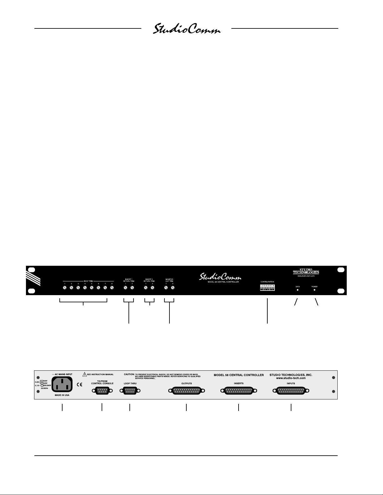
Figure 1. Model 58 Central Controller Front Panel
Input
trimpots
Insert 1
return trimpots
Figure 2. Model 58 Central Controller Back Panel
AC mains
connection
To/from
Model 59
Control
Console
to additional
return trimpots
Loop thru
connector
Model 58
Insert 2
Monitor out
trim pots
connections
Output
Insert
connections
Configuration
DIP switches
Data
active LED
Input
connections
Power
present LED
Issue 2, April 1998 Model 58/59 User Guide
Page 8 Studio Technologies, Inc.
Page 9
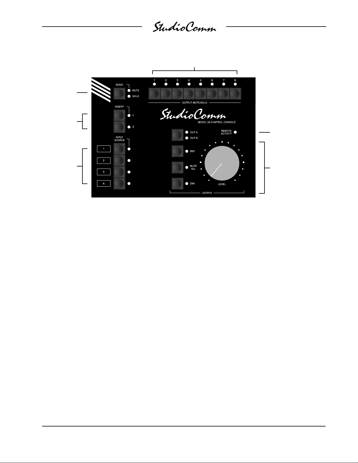
Mute/solo
mode select
Inserts 1 & 2
Input
Sources
1-4
for Surround
Output channel
mute/solo
Remote control
input
activity LED
Monitor Output
• Output A/B select
• Reference level
• Mute all
• Dim
• Rotary level control
Figure 3. Model 59 Control Console Front Panel
operating configuration simply depends on
the number of Model 58 Central Controller
units which are connected.
The Model 59 provides four buttons and
associated LEDs for selection of the input
source to be monitored. While in most
cases only one input source will be monitored at a time, multiple inputs can be
selected for simultaneous monitoring. This
allows two, three, or all four of the inputs
to be combined (“summed”). While there
is no independent control of the input
levels, this feature can be useful for creating rough mixes from the source signals.
It is also a fast, effective means of making
a “seat-of-the-pants” check on the phase
relationship between synchronized
signals.
The monitor output level is controlled
either through the use of a large, easyto-use rotary control, or by enabling the
preset reference level. For operator convenience, the dim function allows the
monitor output level to be reduced by a
fixed dB amount. The mute all function
disables all monitor outputs by activating
the mute relays on the Model 58 Central
Controller units. A push-button switch and
two LEDs are used to select the desired
monitor output—either A or B.
The StudioComm’s two insert sections are
directly accessible using push-button
switches. While they can perform a standard insert action, they can also be used
to provide a wide range of muting, routing,
and summing functions. Each insert can
be configured, on a channel-by-channel
basis, to act in one of four modes: Mute,
maintain connection of the normal signal,
insert the return signal in place of the
normal signal, or sum the return signal
with the normal signal.
Model 58/59 User Guide Issue 2, April 1998
Studio Technologies, Inc. Page 9
Page 10
for Surround
Control of the individual output channels
is provided by the mute/solo section. One
push-button switch sets the operating
mode for either mute or solo. In the mute
mode, individual channels can be muted
or un-muted as required. In the solo mode,
one channel can be monitored while the
others are automatically muted. (Of
course, multiple channels can be simultaneously selected for “soloing.”) The flexibility of having both mute and solo
available allows an operator to quickly
select the most comfortable and productive operating mode.
A major strength of the Model 59 is the
ability to configure, under software control,
many operating parameters. During initial
installation the Model 59 is “taught” the
number of output channels to be controlled, the number of channels associated
with each of the four inputs, and the routing to be performed by the insert sections.
The monitor output reference level is set
by taking an electronic “snapshot” of the
position of the rotary level control. The dim
level is selected from among four choices.
A number of other operating parameters
can also be configured, including how the
remote contact and level control inputs will
function. All configuration parameters are
stored in non-volatile memory.
A Model 59 Control Console connects to
a Model 58 Central Controller using a
standard 9-pin D-subminiature cable.
Multiple Model 58 units connect together
in a bus fashion. Power for the Model 59
is provided by the Model 58s. The Model
59 generates MIDI system-exclusive
messages to control the Model 58 units.
Remote control signals connect to the
Model 59 via pins in the 9-pin interconnecting cable.
Remote Control Capability
Three remote control functions can be
easily implemented: Mute all or dim, insert
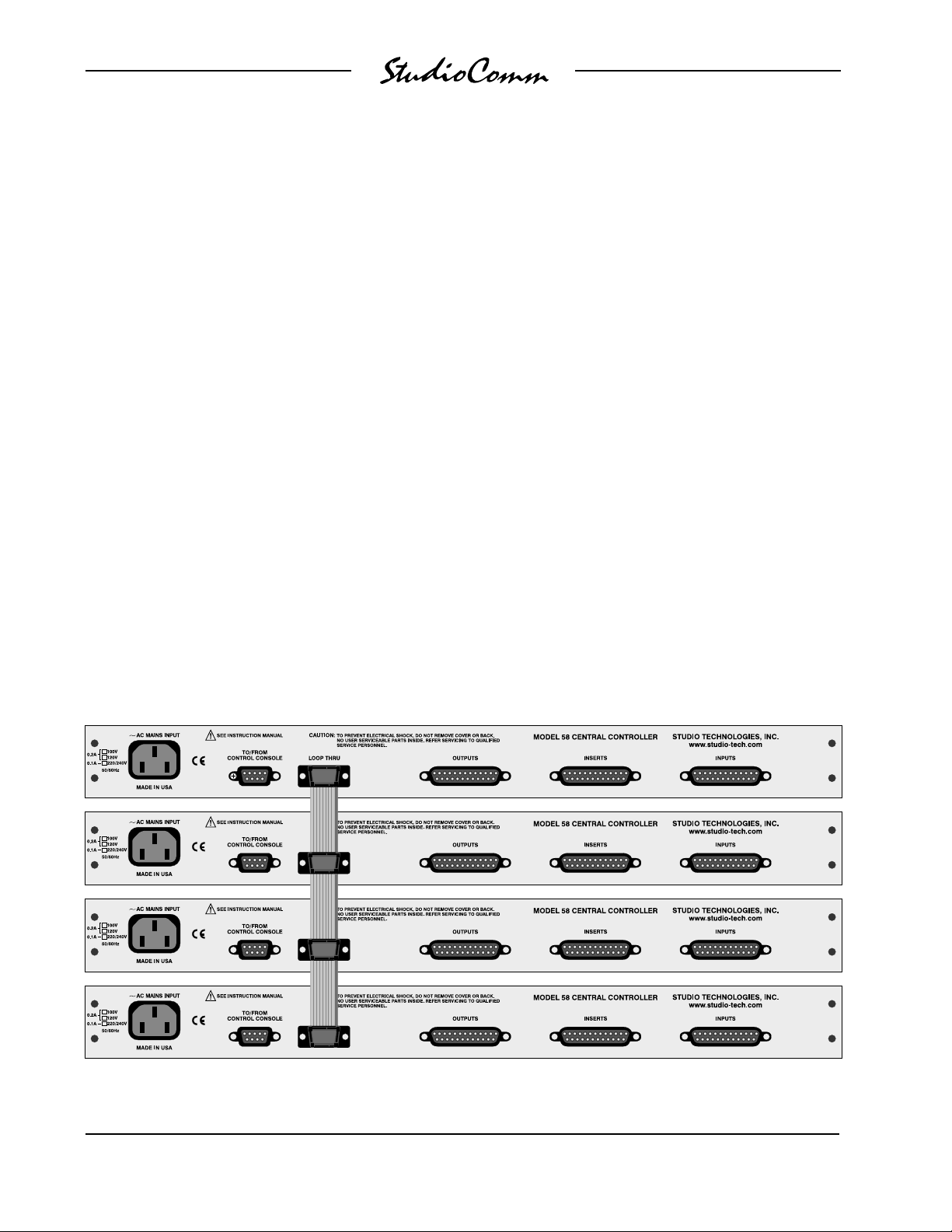
Figure 4. Multi-Channel Monitor System Showing Four Model 58 Central Controllers Interconnected
with Bus Assembly
Issue 2, April 1998 Model 58/59 User Guide
Page 10 Studio Technologies, Inc.
Page 11

for Surround
1 or 2 enable, and monitor level. Contact
input 1 can be configured as either a
remote mute all or a remote dim function.
This supports external functions such as
talk back or slate. Contact input 2 can
be used to remotely enable insert 1 or 2,
allowing the PFL/solo function on an audio
console to be interfaced with the StudioComm for Surround system. Using a
standard linear-taper potentiometer, a
remote level control can be implemented;
no special optical encoder or buffer circuitry is required. The remote control
functions allow creation of a secondary
monitoring position, such as a producer’s
or director’s desk or seating location
where level control or muting may be
desired. Provisions have been made in
the StudioComm’s operating software to
ensure that critical listening is not affected
by remote activity.
Expanded Input Capability
In the standard operating mode the Model
59 Control Console is designed to support
up to four Model 58 Central Controller
units. This provides eight output channels,
and allows connection of up to four 8channel sources. A special mode can be
enabled that lets a slightly modified Model
59 support up to eight Model 58 units.
This mode will again support eight output
channels, but will now allow connection
of up to eight 8-channel sources. Specialized playback applications, such as large
screening rooms at motion picture studios,
can benefit from this expanded operating
mode. Contact the factory for details.
Limitations on Signal Routing
While a StudioComm for Surround system
for multi-channel monitoring will do many
wonderful things, it is not designed to
selectively route input signals to the differ-
ent output channels. An input-channel-tooutput-channel relationship is maintained.
A signal that arrives on input 2, channel 6
will, when selected, output only on monitor
and meter output channel 6. Any rerouting
of the input signals must be done prior
to connection to the StudioComm for
Surround system. This should not be
an impairment in most facilities, but it’s
important to highlight this fact.
Applications
Configuration Examples
It can initially be confusing to fully understand how a Model 59 Control Console
and multiple Model 58 Central Controllers
work together to create a multi-channel
monitor system. How the input and output
channels are assigned to the Model 58
units can seem especially tricky. In this
section several examples are provided
that should present a clear picture of
how things go together. A careful review
of the associated diagrams should quickly
make you feel more comfortable. The
flexibility of the StudioComm for Surround
system is both a blessing and a curse. A
simpler system would make installation a
“no brainer,” but in the long run having the
ability to achieve your operational goals is
of overriding importance.
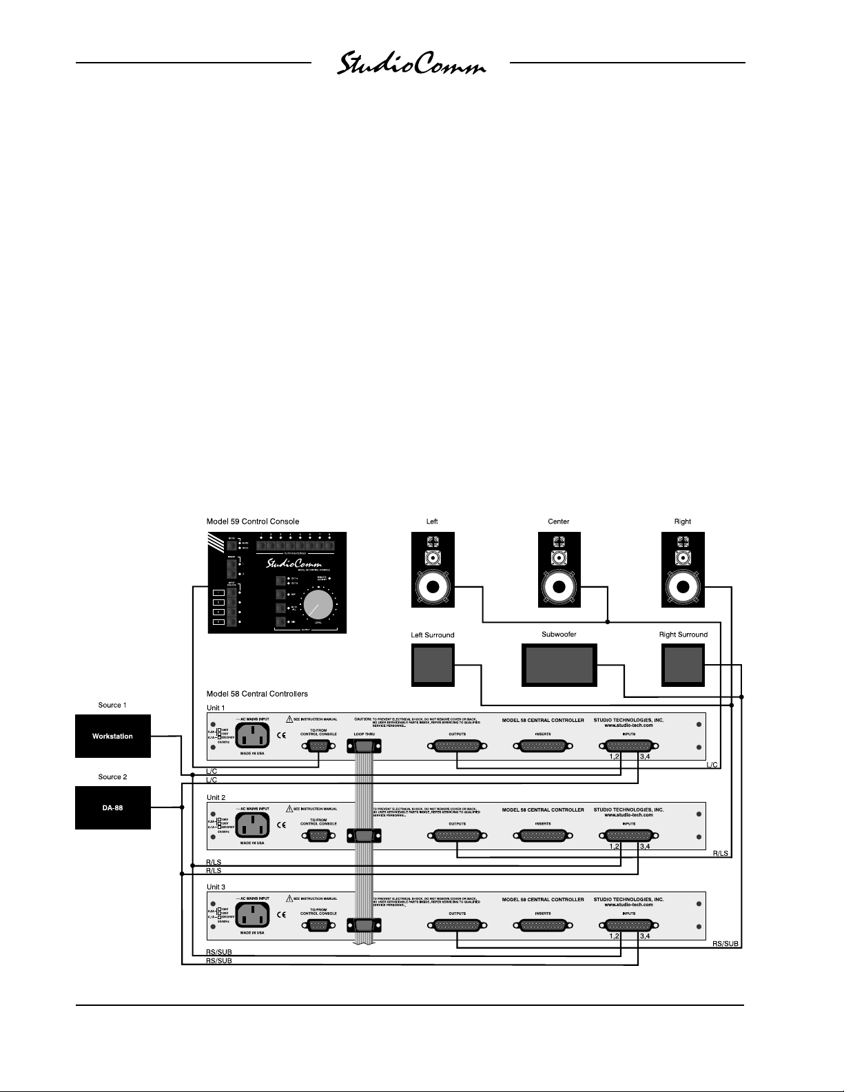
6-Channel (5.1) Configuration
Figure 5 provides an overview of a typical
6-channel installation. The channels are
organized in the standard 5.1 arrangement: left, center, right, left surround, right
surround, and sub. The sub or subwoofer
channel is sometimes referred to as the
LFE (low frequency enhancement) channel. (The term LFE is actually more descriptive but, as of this writing, isn’t as
Model 58/59 User Guide Issue 2, April 1998
Studio Technologies, Inc. Page 11
Page 12
for Surround
commonly used.) Two 6-channel audio
sources and one set of amplified monitor
loudspeakers are connected. Note carefully how the channels are assigned:
Model 58 unit 1 supports the left channel
and the center channel, Model 58 unit 2
supports the right channel and the left
surround channel, and Model 58 unit 3
supports the right surround channel and
the subwoofer channel. Three input and
three output wiring harnesses are required, each connecting to the Model 58s
with 25-pin D-subminiature plugs. These
wiring harnesses are not included with
the StudioComm for Surround system.
The Model 59 Control Console is connected to Model 58 unit 1 using a 9-pin
“D-sub” interconnecting cable. The three
Model 58 units are linked together using
the ribbon cable bus assembly. Both the
9-pin interconnecting cable and ribbon
cable bus are provided with the StudioComm for Surround system. AC mains
power needs to be connected to each
of the three Model 58s. In this example
installation many of the available resources are not utilized, including the
third and fourth 6-channel inputs, the
insert sections, the meter outputs, and
the remote control functions.
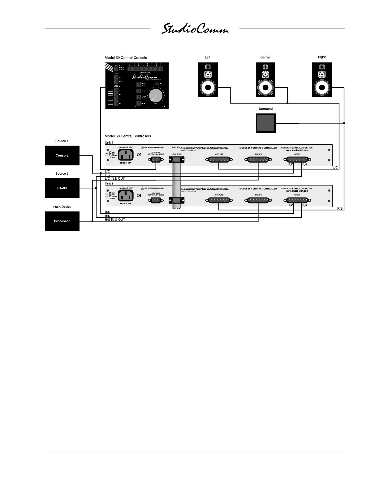
4-Channel (LCRS) Configuration
Figure 6 shows a 4-channel installation
that follows the traditional LCRS format:
Figure 5. Example of 6-Channel (5.1) Configuration
Issue 2, April 1998 Model 58/59 User Guide
Page 12 Studio Technologies, Inc.
Page 13
for Surround
Figure 6. Example of 4-Channel (LCRS) Configuration
left, center, right, and surround. Again,
two 4-channel sources are connected,
along with one set of amplified loudspeakers. The left and center channels are
supported by Model 58 unit 1, while the
right and surround channels are supported
by Model 58 unit 2. A processor device is
connected to one of the insert sections on
both Model 58 units. Two input, two insert,
and two output wiring harnesses are
utilized for audio interconnection.
The Model 59 Control Console is connected to Model 58 unit 1, and both Model
58s are interconnected using the ribbon
cable bus assembly. AC mains power
must be connected to both Model 58 units.
Many features are available for future use,
including inputs 3 and 4, the second insert
section, the meter outputs, and the remote
control functions.
Inserts
The Model 58 insert sections are applicable for far more than the usual console
inserts functions. Under control of the
Model 59 Control Console, each insert
channel can independently function in
one of four modes: mute normal signal
flow, maintain the normal signal flow,
replace the normal signal with the return
signal, or sum (combine) the return signal
with the normal signal. (Note that in all
cases the insert send signal will remain
active.) With this flexibility the inserts can
be used for a variety of insert, routing, and
mixing functions.
Using the insert returns, in conjunction
with contact input 2, allows a console’s
AFL/solo system to be directly integrated.
The console’s source of AFL/solo audio
Model 58/59 User Guide Issue 2, April 1998
Studio Technologies, Inc. Page 13
Page 14

for Surround
(usually the stereo monitor output) can be
connected to the insert returns associated
with the left and right channels. With this
arrangement, whenever the console’s
AFL/solo system is active, the audio will
automatically be monitored, overriding the
normal audio source. (Refer to the remote
control input paragraphs of the Installation
section for details on connecting to contact
input 2.)
The decision as to which insert section to
utilize for an AFL/solo function depends on
how the AFL/solo signal should flow
through the system; pre or post, relative
to the other insert section. In most cases
using insert 2 is preferable, ensuring that
the AFL/solo signal will not be processed
by insert 1.
A “phantom” center channel can be easily
created by connecting the insert send of a
surround channel to the insert returns on
the channels designated for left and right.
However, with this implementation, a level
“buildup” problem may occur. If this is the
case, the source of the phantom center
may need to be attenuated by 6dB (voltage). This would be easily accomplished
using a resistor “pad” to drop the level.
With the insert sends capable of driving
600 ohm loads, a simple three resistor
pad would work well; two 150 ohm and
one 300 ohm resistor would do the trick.
Remote Control
Provision has been made to allow remote
control of several operating parameters.
Contact input 1 allows remote activation
of the mute all or dim functions. Contact
input 2 allows remote activation of the
insert 1 or insert 2 functions. The level
control input allows remote control of the
monitor output level. The exact functioning
of the remote inputs is dependent on the
configuration of Model 59 Control Console
parameters. Refer to the Configuration
section of this guide for details.
Remote control of mute all or dim is provided to allow a variety of applications to
be supported. Placing a mechanical switch
adjacent to a telephone, allowing personnel to conveniently mute the monitor
loudspeakers, is a perfectly acceptable
application. Allowing a talk-back system to
automatically dim the monitors is another
typical application.
Remote control of insert 1 or insert 2 was
specifically provided to support interfacing
with an associated console’s PFL/solo
system. By connecting to an electronic
signal that indicates when the PFL/solo
system is active, audio signals connected
to insert return 1 or 2 will be automatically
monitored.
The remote level control input is one of
those features which is rarely going to be
used, but if you need it, you’ll really need
it! (Without having support built into the
Model 59 Control Console’s hardware and
software, it would be almost impossible to
add a remote level control later.) The
remote level control input was provided
specifically to allow a producer, director,
or other “big cheese” to have their own
level control for use when previewing
motion picture or video work-in-process.
The remote level control input, along with
the remote mute all and dim functions,
makes it simple to create a small control
console for secondary locations.
Note that software “smarts” in the Model
59 Control Console inhibits the use of the
remote level control any time the operator
selects the reference output level. This
Issue 2, April 1998 Model 58/59 User Guide
Page 14 Studio Technologies, Inc.
Page 15

for Surround
ensures that the calibrated monitor level
won’t accidentally be changed by some
maroon. This, along with a remote activity
LED indicator on the Model 59, keeps the
remote level control from doing more harm
than good.
Installation
In this section you will be installing the one
or more Model 58 Central Controllers in an
equipment rack. Multiple Model 58 units
will be interconnected using the bus assembly. Audio input, insert, and output
connections will be made. A location will
be selected for the Model 59 Control
Console, and it will be connected to one
of the Model 58 units. If required, external
equipment will be interfaced with the
remote control inputs. AC mains power
will be connected to the Model 58 units.
System Components
The main shipping carton contains the
Model 58/Model 59 base configuration.
This consists of one each of the following:
Model 58 Central Controller, Model 59
Control Console, 20-foot (6.1m) 9-pin
D-subminiature interconnecting cable,
ribbon-cable bus assembly, User Guide,
and warranty card. Units destined for
North America also include an AC mains
cord. Your dealer or distributor will provide
an AC mains cord for non-North American
destination. Each additional Model 58
Central Controller is shipped in a separate
carton. These Model 58 “solo” units include a warranty card and, where applicable, an AC mains cord.
Mounting Model 58 Central
Controllers
Each Model 58 Central Controller requires
one space in a standard 19-inch (48.3cm)
equipment rack. Select a location that is
convenient to both the analog audio signals and the Model 59 Control Console.
A 20-foot (6.1m) cable is supplied to
connect the Model 58 units to the Model
59. You can supply your own interconnecting cable, however 50 feet (15.3m) is the
recommended maximum length. Secure
each Model 58 in the equipment rack
using two mounting screws per side.
Consider selecting a mounting location
that can accommodate future expansion.
If, for example, you are installing three
Model 58 units to create a 6-channel
system, you may want to leave room in the
rack for one additional Model 58. This will
make upgrading to an 8-channel system
simple; install a fourth Model 58 and
you’re ready to go.
Interconnecting the Model 58
Units
In most applications multiple Model 58
units are going to be used together to
create a multi-channel monitor system. To
assist in this purpose, a ribbon-cable bus
assembly is provided with each Model 58/
Model 59 base configuration. The bus
assembly contains four 9-pin D-sub plugs,
spaced 2 inches apart, allowing up to four
Model 58s to be interconnected. Refer to
Figure 4 for a diagram depicting the interconnection of four Model 58 units. Each
Model 58 contains a 9-pin D-sub connector labeled LOOP THRU. Use the bus
assembly to link these connectors together. Locking hardware for the plugs
is not included as it is unnecessary for
Model 58/59 User Guide Issue 2, April 1998
Studio Technologies, Inc. Page 15
Page 16

for Surround
reliable interconnection. (If you are the
compulsive type, the D-subs on the Model
58 use 4-40 threads.)
Audio Input, Output and Insert
Connections
Audio input and output connections are
made by way of three 25-pin D-subminiature (“D-sub”) connectors. Located on the
Model 58’s back panel, the connectors are
labeled INPUTS, INSERTS, and OUTPUTS. Three cable harnesses, each with
a 25-pin D-sub plug (male) on one end,
and the desired connectors on the other
end, are necessary. These cable harnesses are not supplied by Studio Technologies.
The wiring scheme used by the D-subs
comply with that made familiar by
TASCAM with their DA-88 product. A
wiring harness prepared for the Model 58
input channels would be identical to that
of a DA-88 input harness. A wiring harness prepared for the Model 58 output
channels would be identical to that of a
DA-88 output harness. A harness for the
Model 58 inserts and outputs would be
wired in a slightly different fashion. Please
refer to Figures 7, 8, and 9 for exact connection details. Note that the Model 58’s
D-sub connectors use 4-40 threads.
When it came time for Studio Technologies to test the first Model 58 Central
Controller, standard DA-88 harnesses
were purchased. They turned out to be
of very good quality, and at a reasonable
price. Unless there’s a special need, it
may be cost and time effective for you to
purchase commercially made cable assemblies. Let the large market for DA-88style cabling help you painlessly install
your system!
Line Inputs
The connector labeled INPUTS is used to
interface with the eight line input circuits.
Please refer to Figure 7 for details on the
exact “pin out” of the D-sub connector.
The electronically balanced input circuitry
is intended for connection to balanced or
unbalanced sources with a nominal signal
level of +4dBu. A trim potentiometer is
associated with each input, allowing adjustment of the input sensitivity over a
±2dB range. The configuration sections of
this guide provides details on using the
trim pots.
Balanced sources should be wired so that
signal high is connected to + on the D-sub,
signal low to – on the D-sub, and shield to
the D-sub’s shield connection. With an
unbalanced source connect signal high to
the + connection on the D-sub, and shield
to both the – and the shield connection on
the D-sub. If connecting to an unbalanced
source in this manner results in hum or
Signal Signal
Connection High (+) Low (–) Shield
IN 1-1 24 12 25
IN 1-2 10 23 11
IN 2-1 21 9 22
IN 2-2 7 20 8
IN 3-1 18 6 19
IN 3-2 4 17 5
IN 4-1 15 3 16
IN 4-2 1 14 2
Notes: 1) Connector type on Model 58 is 25-pin
D-subminiature female. Installer must
provide plug (male). Connector uses 4-40
threaded inserts for locking with mating plug.
2) Wiring scheme follows Tascam DA-88
convention. Standard DA-88-type wiring
harnesses are directly compatible, with the
exception of 4-40 screw threads being
required.
Figure 7. Connector Pin Out for Inputs
Issue 2, April 1998 Model 58/59 User Guide
Page 16 Studio Technologies, Inc.
Page 17
for Surround
noise, connect signal high to + on the
D-sub, and shield to – on the D-sub; leave
the shield connection on the D-sub
unterminated.
It is important that at least one of the
multi-channel inputs be wired by way of an
audio patch bay. This will allow the channels associated with an input source to be
easily rerouted. While signals generated
within a facility will usually follow a specific
format, such as L, C, R, LS, RS, Sub, it is
possible that media provided by an outside
source will follow a different one.
Outputs
The connector labeled OUTPUTS provides access to the two, 2-channel monitor
outputs and the 2-channel meter output.
Please refer to Figure 8 for details on the
exact “pin out” of the D-sub connector.
Signal Signal
Connection High (+) Low (–) Shield
MONITOR A-1 24 12 25
MONITOR A-2 10 23 11
MONITOR B-1 21 9 22
MONITOR B-2 7 20 8
METER 1 18 6 (See Note 3) 19
METER 2 4 17 (See Note 3) 5
NOT USED 15 3 16
NOT USED 1 14 2
Notes: 1) Connector type on Model 58 is 25-pin
D-subminiature female. Installer must
provide plug (male). Connector uses 4-40
threaded inserts for locking with mating plug.
2) Wiring scheme loosely follows Tascam
DA-88 convention. Modified DA-88-type wiring
harnesses are required, along with 4-40 screw
threads.
3) Meter outputs are unbalanced. Pins 6 and
17 internally connected to Model 58 shield.
Figure 8. Connector Pin Out for Outputs
The monitor outputs are intended for
connection to audio amplifiers associated
with monitor loudspeakers, or to the inputs
of loudspeakers with integrated amplifiers.
Note that there are two monitor output
circuits which are switched, using relays,
to the 2-channel A and B output connections. Under normal operation only one
set of outputs, A or B, will be active at
the same time. The output which is not
active has a short-circuit placed across
its connections.
Note: While the electronically balanced
output circuits are capable of driving
loads of 600 ohms or greater, the output level will drop slightly as the load
impedance approaches 600 ohms. A
0.5dB difference in output level can
be expected as the load impedance
changes from 10k ohms to 600 ohms.
This applies to all of the electronically
balanced output circuits provided on
the Model 58.
The monitor outputs are electronically
balanced and are capable of driving balanced or unbalanced loads of 600 ohms
or greater. While balanced operation is
preferred, unbalanced operation does not
pose a problem. To connect to an unbalanced load connect the + terminal of the
D-sub as signal high, and both the – and
shield as the signal low/shield. For optimal
unbalanced operation, it is important to
connect both – and shield together directly
on the D-sub, and not at the other end of
the harness.
The same source, or sources, that feed
the monitor outputs are fed to meter outputs. The major difference is that the
meter outputs are not affected by the
Model 58/59 User Guide Issue 2, April 1998
Studio Technologies, Inc. Page 17
Page 18

for Surround
monitor output level control circuitry; they
are pre-fader (pre-VCA).
The meter outputs are intended for connection to the inputs of various mechanical, electronic, or electromechanical meter
systems. These could range from conventional analog “VU” or “PPM”-type meters,
to projection meter systems used in motion picture applications. The meter outputs can also serve as an additional audio
output for special applications, such as a
copy or “dub” output. In addition, the meter
outputs serve an important role in the input
calibration process, which is discussed in
the Configuration section of this guide.
The meter outputs are unbalanced, have
a nominal level of +4dBu, and are capable
of driving loads of 600 ohms and greater.
Even if the meter outputs are not going to
be used during normal operation it is
important to provide access to them. To
correctly and accurately calibrate the
system input-to-output gain an audio level
measurement device must be able to be
temporarily connected to the meter outputs. While not absolutely necessary,
terminating or routing the meter outputs
to points on an audio patch bay may prove
very helpful for long-term maintenance
assistance.
Inserts
The connector labeled INSERTS is used
to interface with the two, 2-channel insert
sections. Please refer to Figure 9 for
details on the exact “pin out” of the D-sub
connector. The use of the insert sections
will depend on the requirements of the
specific installation. In certain cases the
inserts sections won’t be required, and
no connections will need to be made.
The insert sends are electronically balanced, have a nominal level of +4dBu, and
are capable of driving balanced or unbalanced loads of 600 ohms or greater. While
balanced operation is preferred, unbalanced operation is not a problem. To
connect to an unbalanced load connect
the + terminal of the D-sub as signal high,
and both the – and shield as the signal
low/shield. For optimal unbalanced operation, it is important to connect both – and
shield together directly on the D-sub, and
not at the other end of the harness.
Note that the insert sends do not have
level trim potentiometers associated with
them. The output levels are nominally
+4dBu, with channel-to-channel variation
of up to ±0.5dB considered normal. It is
anticipated that the equipment connected
to the insert sends will have, if required,
input level adjustment controls.
The insert returns are electronically balanced, have a nominal input level of
Signal Signal
Connection High (+) Low (–) Shield
SEND 1-1 24 12 25
RETURN 1-1 10 23 11
SEND 1-2 21 9 22
RETURN 1-2 7 20 8
SEND 2-1 18 6 19
RETURN 2-1 4 17 5
SEND 2-2 15 3 16
RETURN 2-2 1 14 2
Notes: 1) Connector type on Model 58 is 25-pin
D-subminiature female. Installer must
provide plug (male). Connector uses 4-40
threaded inserts for locking with mating plug.
2) Wiring scheme loosely follows Tascam
DA-88 convention. Modified DA-88-type wiring
harnesses are required, along with 4-40 screw
threads.
Figure 9. Connector Pin Out for Inserts
Issue 2, April 1998 Model 58/59 User Guide
Page 18 Studio Technologies, Inc.
Page 19

for Surround
+4dBu, and are compatible with balanced
or unbalanced sources. A trim pot is associated with each insert return, allowing the
input sensitivity to be adjusted over a
±2dB range. Refer to the Configuration
section of this guide for details on using
the trim pots. Note that connection of
unbalanced sources should follow the
procedure described in the section covering the line inputs.
Connecting the Model 59 to a
Model 58
A cable utilizing a 9-pin D-sub plug (male)
on each end is used to interconnect a
Model 59 Control Console with a Model 58
Central Controller. A 20-foot (6.1m) cable
is provided with each Model 58/Model 59
base configuration.
that is going to be configured with unit ID 1.
Remote Control Connections
The remote control input circuitry is physically located in the Model 59 Control Console. Access to the remote control inputs is
by way of the 9-conductor cable that links
the Model 59 with the Model 58 Central
Controllers. In fact, five of the nine connections in this D-sub are dedicated for use by
the remote control inputs and have nothing
directly to do with the Model 58 Central
Controller. Since all the 9-pin D-sub connectors on the Model 58 units are connected in
parallel, access to the remote control inputs
is made using any available 9-pin D-sub on
any of the Model 58 units. Refer to Figure
10 for a detailed description of the 9-pin
D-sub connections.
Should a cable of different length be
required it should be wired in a one-to-one
fashion for all 9 pins. Pin 1 carries signal
common, and must be connected at both
ends. A shield connection from the cable
should be connected to pin 1 at one, or
both, ends. For best performance the
cable generally should not exceed 50 feet
(15.3m) in length. The reality is that a
cable much longer in length should work,
as long as an excellent-quality cable is
utilized. We define “excellent” as extensive
shielding along with very low capacitance.
The low cable capacitance limits the
amount of data-signal waveform distortion.
As far as the maximum length, go ahead
and try it—if it works, it works!
Each Model 58 contains a 9-pin D-sub,
labeled TO/FROM CONTROL CONSOLE.
Select one of these for connection to the
Model 59. While it doesn’t technically
matter which Model 58 is selected, it is
often best for clarity to use the Model 58
Pin Signal Direction
1 Common, Model 58 units to
2 +15V Model 58 units to
3 Data Current Model 59 to
4 Common Model 59 to
5 Contact Input 1 Remote Contact to
6 Contact Input 2 Remote Contact to
7 CCW Remote Level
8 Wiper Remote Level
9 CW Remote Level
Notes: 1) Connector type on Model 58 is 9-pin D-subminiature
Figure 10. Connector Pin Out for Control
Console and Loop Thru Connections
Power Supply Model 59
Model 59
Source Model 58 units
Model 58 units
Model 59
Model 59
Level
Control
female. Connector uses 4-40 threaded inserts for
locking with mating plug.
Potentiometer to Model 59
Potentiometer to Model 59
Potentiometer to Model 59
Model 58/59 User Guide Issue 2, April 1998
Studio Technologies, Inc. Page 19
Page 20

for Surround
Contact input 1 and contact input 2 are
+5V logic signals which are active when
they are brought to the logic low state.
While the inputs are protected from overcurrent and static (ESD) discharge care
should be taken to prevent nasty signals
from reaching them. To activate contact
input 1 simply connect pin 5 to system
common, pin 4. To activate contact input 2
connect pin 6 to pin 4. The contact inputs
are active when held in the low state; they
can’t be configured to change states
(“latch”) in response to a logic pulse.
All that is required to add a remote level
control is to connect a commonly available
linear taper potentiometer. (Yes, use a
linear pot! Software in the Model 59 Control Console converts its performance to
log.) Any high-quality pot with a nominal
“coil” resistance of between 1k and 25k
ohms should work fine. Simply connect
the pot in this fashion: pin 7 to counterclockwise, pin 8 to wiper, and pin 9 to
clockwise. As very little current travels
through the wiring and pot, there is really
no practical maximum cable length. Be
aware that the longer the cable run, the
more chance that an accidental short
circuit could take place. This would cause
the monitor level to go to maximum.
AC Mains Power
The Model 58 is internally configured to
operate from either 100, 120, or 220/240V,
50/60Hz. Units shipped to North America
are factory selected for 120V operation.
Units bound for Japan are selected for
100V, while our friends “down under” and
in Europe receive units set for 220/240V.
Before connecting the Model 58 to mains
power, check that it is configured to match
the local mains voltage. Look on the back
panel (adjacent to the power entry connector) for the configured voltage(s). Note
than an incorrect configuration could
seriously damage the unit. Should it be
necessary to change the unit’s operating
voltage it must be performed only at the
factory or by an authorized service
technician.
The Model 58 uses an IEC standard
connector to mate with the AC mains
cord. The wire colors in the AC mains
cord should conform to the internationally
recognized CEE color code and must be
wired accordingly:
Connection Wire Color
Neutral (N) Light Blue
Line (L) Brown
Protective Earth (E) Green/Yellow
Warning: Connecting to the remote
level control input requires very careful
attention to wiring and potentiometer
connections. Shorting pin 8 of the 9-pin
D-sub connector to common will raise
the monitor output level to maximum!
To address hearing safety issues, the
Model 59 is default configured to disable the remote level control input. A
safe and reliable installation must be
Safety Warning: The Model 58 does
not contain an AC mains disconnect
switch. As such, the mains cord plug
serves as the disconnection device.
Safety consideration requires that
the plug and associated outlet be
easily accessible to allow rapid disconnection of mains power should it prove
necessary.
completed prior to enabling the input.
Issue 2, April 1998 Model 58/59 User Guide
Page 20 Studio Technologies, Inc.
Page 21

for Surround
As soon as mains power is applied, the
Model 58’s power present LED will light.
The Model 59 will go through its power-up
sequence lighting each LED in a rapid
sequence.
Note that any time a Model 58 configuration DIP switch is changed, mains power
on all Model 58 units must be discon-
nected and reconnected. This ensures
that the logic circuitry is fully reset to the
new operating parameters. (This is not a
bug in software—we designed it this way
to ensure that the performance would be
correct!) Refer to the Configuration section
of this guide for details on setting the DIP
switches.
Configuration
After the physical installation has been
completed, several configuration issues
must be addressed. On the Model 58
Central Controllers, the unit ID and operating mode must be set. In addition, the
input and output signal levels must be
calibrated using the trim potentiometers.
As a final step, the operating parameters
of the system will be set using the Model
59 Control Console’s configuration mode.
Note that any time a Model 58 DIP switch
is changed, the data LED (located to the
right of the switches) will flash. This is
normal, being provided for factory confirmation of switch operation.
Model 58 Unit Identification
Numbers
A unique unit identification (ID) number
must be assigned to each Model 58.
This allows commands from the Model 59
Control Console can be correctly interpreted. A simple binary method sets the
unit ID, using positions one through four of
an 8-position DIP switch, which is located
on the front panel. The DIP switch positions are labeled 1-8, with position 1 on
the left side. A switch in the off (down)
position is considered to be in the 0 state.
A switch in the on (up) position is considered to be in the 1 state.
Setting the unit ID is very simple: A Model
58 set for unit ID 1 supports output channels 1 and 2 on the Model 59, a Model 58
set for unit ID 2 supports output channels
3 and 4, etc. A system using three Model
58 Central Controllers to create a 6-channel monitor system would have unit ID
numbers 1, 2, and 3 assigned. Refer
to Figure 11 for the exact DIP switch
settings.
You curious types might wonder why four
bits were reserved for unit IDs, rather than
just two or three. In most cases, only the
first four unit ID numbers will be used,
Unit ID DIP Switch 1-4
1 0000
2 1000
3 0100
4 1100
5 0010
6 1010
7 0110
8 1110
9 0001
10 1001
11 0101
12 1101
13 0011
14 1011
15 0111
16 1111
Figure 11. Model 58 DIP Switch Settings for
Unit ID
Model 58/59 User Guide Issue 2, April 1998
Studio Technologies, Inc. Page 21
Page 22

for Surround
allowing creation of an 8-channel monitor
system. In some special applications up to
eight Model 58 units can be used together,
utilizing unit ID numbers 1-8. (This is the
single-channel mode that will be discussed
in Appendix B.) Unit ID numbers 9-16 are
reserved for future applications, the likes
of which even we haven’t the foggiest idea
about—hopefully smart users like you will
come up with some cool ideas for us to
implement!
Model 58 Operating Mode
DIP switch position 5 is used to set the
Model 58 Central Controller’s operating
mode. In the off (down) position, the unit
operates in the normal 2-channel mode.
In the on (up) position, the unit operates
in a special single-channel mode. In the
2-channel mode each Model 58 supports
two output channels and four 2-channel
input pairs. This is correct for use with the
standard Model 59 Control Console. If this
is your application, ensure that DIP switch
5 is in the off (down) position.
The single-channel mode is provided for
special applications where the eight Model
58 input channels need to be routed to the
same output channel. Contact Studio
Technologies for details.
After the Model 58 unit ID and operating mode configurations have been set,
the AC mains power for all units must
be simultaneously disconnected, then
reconnected. This ensures that the
previous configuration is completely
erased and the new one is correctly
implemented.
Level Calibration
Fourteen multi-turn trim potentiometers
grace the front panel of the Model 58
Central Controller. Eight are provided for
the line inputs, four for the insert returns,
and two for the monitor outputs. Taking
time to carefully adjust the trim pots will
ensure that accurate monitoring can take
place. Each trim pot allows an adjustment
range of ±2dB, which is spread over the
trim pot’s 15 turns. Calibrating the levels
down to a tenth of a dB is easily performed.
The meter outputs are used as the measuring point when adjusting 12 of the trim
pots. Unless precision level meters are
already connected to the meter outputs,
a laboratory-grade audio level meter is
required. In addition, the audio sources
connected to the line inputs must be
configured to generate steady signals at
their nominal operating level. Those interested in where the trim pots are located
in the circuitry, and why the meter outputs
are specified as the main measurement
point, should refer to the Model 58 Block
Diagram, located at the end of this guide.
Input Trim Pots
This first procedure will ensure that all
Model 58 line inputs are level matched
against each other. The audio sources
connected to these inputs are normally
arranged as four 2-channel pairs; 1 and 2,
3 and 4, 5 and 6, 7 and 8. The trim pots
will be adjusted in pairs corresponding to
the input sources. In this procedure it is
assumed that precision metering devices
are not connected to the meter outputs.
1. On the first Model 58, connect the
audio level meter to meter output 1.
Issue 2, April 1998 Model 58/59 User Guide
Page 22 Studio Technologies, Inc.
Page 23

for Surround
2. Using the Model 59 Control console,
select input 1 as the audio source.
Be certain that insert 1 and 2 are not
enabled. Enable the mute all function,
ensuring that you won’t have to hear
a steady tone during the entire
procedure!
3. Confirm that the audio source connected to input 1 is generating a
steady signal at precisely its reference
level. (This is assumed to be nominally
+4dBu.)
4. Observing the level meter, adjust input
trim pot 1 to give a +4dBu level at
meter output 1.
5. Disconnect the level meter from meter
output 1 and reconnect it to meter
output 2.
6. Observing the level meter, adjust input
trim pot 2 to give +4dBu.
7. Repeat steps 1-6 for line inputs 2, 3,
and 4.
Once all eight line inputs on the first Model
58 have been calibrated, repeat the entire
procedure for the additional Model 58
units.
The following procedure would be appropriate when an insert section is configured
to place another device in the audio path.
A device commonly used in this type of
application would be a surround sound
encode/decode unit. The procedure also
assumes that precision metering devices
are not connected to the meter outputs.
1. On the first Model 58, connect the
audio level meter to meter output 1.
2. Using the Model 59 Control console,
select input 1 as the audio source.
Confirm that inserts 1 and 2 are disabled. Enable the mute all function,
ensuring that you won’t have to hear
a steady tone during the entire
procedure!
3. Confirm that the audio source connected to input 1 is generating a
steady signal at precisely its reference
level.
4. Observing the level meter, confirm that
the output level is exactly +4dBu. (If
this is not the case, the input trim pot
must be re-calibrated.)
5. Using the Model 59 Control Console,
enable insert 1.
Insert Return Trim Pots
Describing the calibration process for the
insert returns is a bit more difficult as the
exact implementation of the insert sections
is dependent upon the specific installation.
The goal is to have no level change occur
when switching an insert section between
disabled and enabled. Note that the insert
send outputs are not calibrated for a
precise +4dBu nominal level. Trim pots on
the insert returns allow inaccuracies in the
connected device’s input and output levels
6. Observing the level meter, adjust the
trim pot associated with insert 1, return
1 to give a +4dBu level.
7. Disconnect the level meter from meter
output 1 and reconnect it to meter
output 2.
8. Repeat steps 4, 5, and 6 for insert 1,
return 2.
9. If insert 2 is being utilized, repeat the
procedure for its two return trim pots.
to be accounted for.
Model 58/59 User Guide Issue 2, April 1998
Studio Technologies, Inc. Page 23
Page 24

for Surround
Once the insert returns on the first Model
58 have been calibrated, repeat the entire
procedure for the additional Model 58
units.
Monitor Output Trim Pots
A trim potentiometer is associated with
each of the two monitor output circuits.
Note that while there are two 2-channel
monitor output connections—A and B—
there is only one pair of output circuitry.
Relay contacts are used to switch the
output circuits between the A and B connections. Installation-specific requirements
will dictate how the monitor output trim
pots are to be adjusted. In most cases the
trim pots will be adjusted to give exactly
the same output level on all the channels.
Other installations may require the trim
pots to be adjusted in reference to the
outputs of the audio power amplifiers.
For this discussion, we’ll describe how
to match the output levels of the monitor
outputs.
1. Start by turning off the AC mains
power on all audio power amplifiers.
If loudspeakers with integrated amplifiers are being used, turn them off too.
This “power down” is critical, ensuring
that high-level test signals do not get
sent to the loudspeakers. Don’t mess
around—turn off the amps now!
2. Confirm that the audio source connected to input 1 is generating a
steady signal at precisely its reference
level.
3. Using the Model 59 Control Console,
select input 1 as the audio source.
Enable monitor output A. Confirm that
inserts 1 and 2, as well as the mute all
and dim functions are disabled. Slowly
turn the rotary level control clockwise.
If audio is heard, stop raising the level
and turn off any active amplifiers. Turn
the control until it is fully clockwise,
providing the maximum monitor output
level.
4. Connect the precision audio level
meter to channel 1 of monitor output
A.
5. Observing the level meter, adjust
monitor output trim pot 1 to give exactly +4dBu.
6. Disconnect the level meter and connect it to channel 2 of monitor output
A.
7. Observing the level meter, adjust the
monitor output 2 trim pot to give exactly +4dBu.
8. Once the monitor outputs on the first
Model 58 have been calibrated, repeat
steps 4-7 for the additional Model 58
units.
9. On the Model 59 Control Console, turn
the output level control to the fully
counterclockwise position.
10. After confirming that the level control
is fully counterclockwise, activate AC
mains power to the audio amplifiers
or amplified speakers.
Model 59 Operating
Parameters
Many StudioComm for Surround functions
can be configured to meet the exact needs
of your installation. Here’s an overview of
what you can configure:
• Number of output channels to be sup-
ported
• Input signals supported for each input
channel
Issue 2, April 1998 Model 58/59 User Guide
Page 24 Studio Technologies, Inc.
Page 25

for Surround
• Insert routing
• Remote controls
• Monitor output A/B select
• Reference level
• Dim level
The Model 59 Configuration Charts, lo-
cated at the end of this section, give details on how each configuration parameter
is set. An overview of the parameters is
provided in the following paragraphs.
Entering the Configuration
Mode
A small button is located on the back of
the Model 59 Control Console, adjacent
to the 9-pin D-sub connector. Pressing
and holding this button for two seconds
places the Model 59 into the configuration
mode. In the configuration mode the
buttons and LEDs no longer perform their
normal function, but instead allow you to
observe and change many of the operating parameters. The mute/solo mode
LEDs light alternately to indicate that the
configuration mode is active. Once again
pressing and holding the configure button
returns the Model 59 to normal operation.
Note that configuration changes are stored
only after the configuration mode is exited
by pressing and holding the button.
Our apologies to those of you who find the
configure button a pain to use, but it’s
supposed to be that way! Seriously, the
top of the button is slightly recessed from
the back panel, making it harder to accidentally activate. We don’t want normal
operation to cease because someone
pushes the Model 59 into a “rats nest”
of track sheets!
When to Use the
Configuration Mode
There is no problem frequently “tweaking”
the Model 59’s operating parameters to
achieve the desired performance. The
non-volatile memory chip is rated for
thousands of read and write cycles, and
has its retention time rated in years.
Output Channels Supported
The Model 59 hardware and software
supports up to eight output channels. The
Model 59 is configured, from the factory, to
generate commands for all eight outputs.
This would be correct for an installation
that uses four Model 58 Central Controllers operating in their dual-output-channel
mode. But there will often be cases where
one, two, or three Model 58 Central Controllers will be installed, creating 2-, 4-, or
6-channel systems. By configuring the
Model 59 to disable the unused output
channels, operator clarity is enhanced.
Specifically, the output mute/solo mode
buttons and LEDs for the unused output
channels will be disabled, along with the
underlying functionality. With the unused
output channels disabled, an operator
can’t accidentally select those channels
for solo or mute operation.
Supported output channels should always
start at channel 1 and run consecutively to
the last channel. For example, a 6-channel
system should support output channels
1-6, with channels 7 and 8 disabled. A
4-channel system should have channels
1-4 active, and 5-8 disabled.
Input Channels Supported
This configuration is a bit tricky to understand, but it is really quite simple—if we’re
Model 58/59 User Guide Issue 2, April 1998
Studio Technologies, Inc. Page 25
Page 26

for Surround
clear on our explanation, that is! The
number of channels associated with each
of the four inputs is dependent on the
number of output channels. As an example, a system that consists of one
Model 59 Console and three Model 58
Central Controllers supports six output
channels, and four 6-channel input
sources. The configuration parameter for
the number of input channels supported is
provided for those special cases where a
source has less channels than the number
of output channels.
Let’s look further at our mythical example,
the 6-channel system. Inputs 1 and 2 are
connected to 6-channel sources, so everything is fine there. But the source for input
3 is only four channels. While the source
for input 4 is stereo. This makes it not so
“cool” for the operator to select input 3 or 4
for monitoring, as the unused input channels will get routed to the meter and monitor outputs. Will the unused input channels
pick up lots of noise and hum? Unlikely,
but why take the chance of having a problem. Simply use the input channels supported configuration to disable the unused
channels associated with inputs 3 and 4.
Now when inputs 3 or 4 are selected, only
the active channels are monitored.
Note that when a channel associated with
an input is disabled, the input routing
circuitry, under software control, no longer
selects it; the corresponding output channel does not mute. With our 6-channel
example, when selecting input 4, the
stereo source, all six output channels
remain active, while the input routing
circuitry does not select the four unused
inputs. While to some this might seem
confusing, and a design fault, it was implemented this way because multiple inputs
can be selected for simultaneous monitor-
ing. A 6-channel source might be selected
at the same time as a stereo source. Having the output mute/solo mode LEDs going
on and off in response to the selected
input sources would be very annoying!
A special mode has been included to
allow an input to be disabled from being
accessed by the operator. This might be
useful, for example, when input 4 is not
connected to a source, and has no valid
reason to be selected. This might also be
useful when connecting a special source
to input 4, such as a house “tie line” or
router output that shouldn’t normally be
accessible. To disable an input is simple,
just disable all eight channels associated
with it. During configuration mode, all eight
LEDs will flash to show that this function
is active. Once the Model 59 is returned
to the normal operating mode the disabled
input simply cannot be selected.
Insert Sections
Configuring the insert sections is an excellent test of your manual dexterity. If you
have any doubts about your ability, don’t
chew gum at the same time! The insert
sections are unique in their ability to be
configured on a channel-by-channel basis.
Each channel of each insert can be independently set for one of four operating
modes: mute normal signal, maintain
normal signal flow, replace the normal
signal with the insert return signal, or mix
the insert return signal with the normal
signal. A detailed explanation of each
mode follows:
Mode 1, mute normal signal. In this mode
no signal flows through the insert section.
This is effectively a channel mute function.
The insert send continues to be active, but
the insert return is not active.
Issue 2, April 1998 Model 58/59 User Guide
Page 26 Studio Technologies, Inc.
Page 27

for Surround
Mode 2, maintain normal signal flow. In
this mode the normal audio signal continues to flow through the insert section. This
is effectively a “no-insert function” function!
The insert send continues to be active, but
the insert return is not active.
Mode 3, replace the normal signal with
the insert return signal. This is the conventional insert function that most consoles
provide. The normal signal no longer flows
through the insert. The return signal is
connected into the signal path.
Mode 4, mix the insert return signal with
the normal signal. In this mode the normal
signal is still active in the signal path, with
the insert return signal mixed (summed)
with it. No level change is performed, they
are mixed at nominal level. Any level
reduction required to prevent “buildup”
needs to be done externally.
If one of the insert sections is going to
used as part of an ALF/solo function, the
individual channels must be carefully
configured. The insert channels that are
connected to the AFL/solo audio should
be set to mode 3. The unused insert
channels must be set to mode 1.
A special mode has been included to allow
an insert section to be disabled from
operation. This is accomplished by configuring all eight channels to mode 2, maintain normal signal flow. With this configuration an operator can press the associated insert button “till the cows come
home” and the function will never activate.
This is another attempt at making the
Model 59 “idiot proof.”
In many cases both insert sections may
not be wired to external devices. This
doesn’t mean that both insert sections
can’t be used effectively. An unused insert
section could be configured to perform
a special mute. An example would be to
configure insert 2 to mute the surround
channels, leaving only the front channels
active. This would give an operator a quick
way of checking the effect of the surround
information on the total mix.
Monitor Output A/B Select
While the Model 58 Central Controller
supports the connection of two sets of
monitor loudspeakers, often only the A
output will be used. The monitor output A/
B select button on the Model 59 Control
Console can be disabled, preventing an
operator from selecting output B. Only the
A LED will be lit, and the button will be
inactive.
Reference Level
For audio-with-picture applications it’s
critical that mixing be done in reference
to a known monitor loudspeaker level. This
is often referred to as mixing to “85dB” on
the monitors. The Model 59 Control Console allows a precise monitor output level
to be stored, and then enabled by pressing
the button labeled REF. Setting the REF
level is very simple:
1. Place the StudioComm for Surround
system in the normal operating mode,
not the configuration mode.
2. Set up a precision sound pressure
level (SPL) measuring device at the
desired listening location.
3. Use the Model 59 Control Console
to select the reference signal source,
e.g., pink noise, as the input source.
Be certain that the ref and dim functions are not active.
Model 58/59 User Guide Issue 2, April 1998
Studio Technologies, Inc. Page 27
Page 28

for Surround
4. Set the Model 59’s rotary level control
to give the precise output level for the
reference setting.
5. Being careful not to touch the position
of the rotary level control, enter the
configuration mode by pressing and
holding the small button on the Model
59’s back panel.
6. Once the configuration mode has been
entered, the output signals will mute.
Again, don’t touch the rotary level
control! Press and hold the reference
button until its associated LED lights.
This will take approximately 5 seconds. The LED lights to indicate that
the new reference level has been
stored.
7. Exit the configuration mode by again
pressing and holding the configure
button, located on the back panel of
the Model 59.
This level is now permanently stored as
the reference level. Only by repeating the
procedure can the value be changed.
The output channels will again become
active. Confirm that the correct level has
been stored by pressing the ref button.
The sound pressure meter should report
your desired level.
Dim Level
The dim function is used to reduce the
monitor output level by a preset amount.
The reduction is in dB relative to the monitor output’s current level. By using the dim
button on the Model 59, you can take a
quick phone call without having to touch
the level control. Also, a remote control
signal can be connected, allowing an
external button or associated equipment to
activate the dim function. There are four
dim level values available: 10, 15, 20, or
25dB.
Restore Factory Defaults
The restore factory defaults function is
provided primarily for factory use. In this
way a system can be shipped with the
default settings selected. While you are
welcome to use this function, be careful
that your configuration efforts may be
wasted. Specifically, note that the reference level is reset to minimum level. All
the other parameters are fairly easy to set
up, but resetting the ref level would require
getting out the SPL meter and a calibrated
signal source. This is a hassle you may
not need!
You might wonder why you have to press
and hold the ref button for 5 seconds
before the value is stored. This is provided
specifically so that some Bozo won’t accidentally change the ref level while they are
playing around with the configuration
mode! You have to know the secret to be
able to store a new value.
Issue 2, April 1998 Model 58/59 User Guide
Page 28 Studio Technologies, Inc.
Page 29

for Surround
Model 59 Configuration Chart—Entering and Exiting
Configuration Mode
&
Press and hold the
configuration button for
2 seconds to enter or exit
the configuration mode.
These LEDs will light alternately
when configuration mode is active.
Model 58/59 User Guide Issue 2, April 1998
Studio Technologies, Inc. Page 29
Page 30

for Surround
Model 59 Configuration Chart—Input Channels Suppor ted
&
Press and hold an input
button (one at a time) to
display and select which
channels associated with
that input will be active.
When an input button
is pressed, use these
buttons to select which
input channels will be
active for that input.
When an input button is
pressed, these LEDs display
which input channels are
active for that input. A lit LED
indicates that the channel is active.
Default: All eight possible input sources are active for each input.
Note: When all channels associated with an input are disabled, all LEDs will flash to indicate this condition.
In this mode the input is disabled from use during normal operation. If an input is not going to have a
source associated with it, deselect all input channels! Then during normal operation this input will not be
able to be selected, minimizing the confusion caused by selecting an invalid input source.
Issue 2, April 1998 Model 58/59 User Guide
Page 30 Studio Technologies, Inc.
Page 31

for Surround
Model 59 Configuration Chart—Output Channels Suppor ted
&
Press and hold the mode
button to display and
configure the number of
output channels to be active.
When the mode button is
pressed, use these buttons
to select which output
channels are to be active.
When the mode button is pressed,
the LEDs display which output
channels are to be active. An
LED that is lit indicates that its
associated output channel is active.
Default: All eight output channels active.
Note: When no outputs are selected to be active all the LEDs flash to indicate an error condition.
Model 58/59 User Guide Issue 2, April 1998
Studio Technologies, Inc. Page 31
Page 32

for Surround
Model 59 Configuration Chart—Insert 1 and 2
When an insert button and
an output channel button is
pressed at the same time,
use these buttons to select
the insert mode.
&
Press and hold one of the
insert buttons to allow the
display and selection of
the insert mode.
When an insert button is
pressed, pressing the output
buttons (one at a time) allows
the display and selection of
the insert mode.
When an insert button and an output
channel button is pressed at the same
time, the insert mode is displayed.
LED 1 lit means mode 1, mute normal signal flow;
LED 2 lit means mode 2, maintain the normal signal flow;
LED 3 lit means mode 3, replace the normal signal with the return signal;
LED 4 lit means mode 4, sum (combine) the return signal with the normal signal.
Default: All channels associated with both inserts are in mode 3, return audio replaces normal audio.
Note 1: This is the hardest configuration to understand and perform! Two buttons must be simultaneously pressed
to display the mode; three buttons must be simultaneously pressed to change a configuration. A little
practice and it becomes easy!
Note 2: If all channels are set for mode 2 the insert function is disabled. This feature is provided so that the
operator won’t attempt to enable an unused insert, hopefully minimizing confusion.
Issue 2, April 1998 Model 58/59 User Guide
Page 32 Studio Technologies, Inc.
Page 33

for Surround
Model 59 Configuration Chart—Output Mode
When the Out A/B button is pressed,
use these buttons to select the
output mode. Press button 1 for the
A only output mode; button 2 for the
A or B output mode.
When the Out A/B button is pressed,
the LEDs display the output mode.
When LED 1 is lit the A only output
mode is selected; when LED 2 is lit
the A or B output mode is selected.
&
Press and hold the
Out A/B button to
display and select
the output mode.
Default: A or B output mode.
Model 58/59 User Guide Issue 2, April 1998
Studio Technologies, Inc. Page 33
Page 34

for Surround
Model 59 Configuration Chart—Setting Ref Level
&
Press and hold the Ref button for
5 seconds to take a “snapshot” of
the rotary level control’s present
setting. The Ref LED will light
when the value has been stored.
Default: Fully attenuated (minimum) output level.
Note: The 5-second delay is a safety feature, ensuring that the ref level will not be accidently changed.
Issue 2, April 1998 Model 58/59 User Guide
Page 34 Studio Technologies, Inc.
Page 35

for Surround
Model 59 Configuration Chart—Dim Level and Remote Input
Parameters
When the dim button
is pressed, press
these buttons to
select the dim level.
These LEDs display the status of remote
control input 1. LED 1 lit means that the
input is disabled. LED 2 lit means that the
input provides a remote mute all function.
LED 3 lit means that the input provides a
remote dim function. Use the buttons to
change modes.
These LEDs display the status of remote
control input 2. LED 4 lit means that the
input is disabled. LED 5 lit means that the
input provides a remote insert 1 function.
LED 6 lit means that the input provides a
remote insert 2 function. Use the buttons
to change modes.
These LEDs display
the status of the
remote level control
input. LED 7 lit means
that the remote level
control input is
disabled. LED 8 lit
means that the
remote level control
input is enabled. Use
the button to change
modes.
When the dim button is pressed, the
LEDs display the selected dim level:
LED 1 lit means 25dB dim;
LED 2 lit means 20dB dim;
LED 3 lit means 15dB dim;
LED 4 lit means 10dB dim.
Default: 20dB dim level, remote control inputs 1 and 2 disabled, remote level control input disabled.
Model 58/59 User Guide Issue 2, April 1998
Studio Technologies, Inc. Page 35
&
Press and hold the dim
button to display and
select the dim level and
remote input parameters.
Page 36

for Surround
Model 59 Configuration Chart—Restore Factory Defaults
&
Press and hold both insert buttons
for 5 seconds for the Model 59 to
restore its factory defaults. Once
defaults have been restored, both
insert LEDs will light until the
buttons are released.
Factory Defaults: All eight possible input sources are active for each input.
All eight output channels will be active.
All channels associated with both inserts are in mode 3, return audio replaces normal audio.
A or B output mode.
Fully attenuated (minimum) output level.
20dB dim level, remote control inputs 1 and 2 disabled, remote level control input disabled.
Note: The 5-second delay is a safety feature, ensuring that the factory defaults will not be accidently restored.
Issue 2, April 1998 Model 58/59 User Guide
Page 36 Studio Technologies, Inc.
Page 37

for Surround
Operation
Now that you’ve installed and configured
the system, you’re ready to go. You should
find operation very easy.
Model 58 Central Controller
The Model 58 front panel contains two
LEDs. The power LED should be lit whenever AC mains power is connected. The
data LED will light whenever a MIDI system-exclusive message matching the
Model 58’s configuration is received. With
multiple Model 58s installed, you’ll notice
that sometimes all the data LEDs will light
simultaneously, and sometimes they’ll light
independently. The patterns you’ll see are
simply in response to the commands
coming from the Model 59. If an operator
presses the mute all button, the command
generated is applicable to all Model 58s,
so all the data LEDs will light. If an operator “solos” an individual channel, only one
Model 58 will respond to the command.
Model 59 Control Console
The StudioComm for Surround functions
are controlled using the Model 59 Control
Console and, if installed, the remote contacts and level control. To make things
easy to describe, we’ve divided the
StudioComm for Surround functions into
five main groups: input source selection,
inserts, monitor output general functions,
mute/solo, and remote controls.
Input Source Selection
Input source selection is simple. To select
an input source for routing to the meter
and monitor outputs, press one of the four
input source buttons. The corresponding
LED will light to let you know that the input
has been selected. You can select more
than one input source simultaneously;
up to all four. The selected inputs will be
summed (combined). Start by pressing
and holding the button associated with
your first input source. While the button
is still pressed, add the extra inputs by
momentarily pressing the buttons associated with them. The LEDs will light to tell
you which inputs have been selected.
A special configuration mode allows an
input to be disabled. This would be appropriate if an input has not been connected
to an audio source. If you press an input
source button and the current source does
not change, the input has been disabled.
Inserts
Activating the two insert sections is as
simple as pressing the insert buttons.
When an insert function is active, its associated LED will be lit. Because of the
flexibility that is built into the insert functions it may be important for an operator
to understand how they are configured.
An insert may be configured to operate
in the usual manner (adding a processing
device into the audio path) or may be used
for another summing, routing, or muting
function.
In some cases, an insert section may have
been connected and configured to work in
conjunction with an audio console’s AFL/
solo function. If this is the case, pressing
the insert button will result in no action
occurring. However, when the AFL/solo
function is active, the insert LED will flash,
as will the remote activity LED.
A special configuration mode allows the
inserts to be disabled. This would be
appropriate if one or both the insert sections were not going to be used. In this
Model 58/59 User Guide Issue 2, April 1998
Studio Technologies, Inc. Page 37
Page 38

for Surround
case, pressing an insert button would
result in no action.
Monitor Output General Functions
Four buttons and one rotary control are
associated with the monitor output function. The buttons are A/B output select,
reference level, mute all, and dim. The
rotary level control is used to set the
monitor output level.
A/B Output Select
The A/B button is used to select the set
of monitor outputs to be connected to the
Model 58’s output circuitry. Two LEDs are
associated with the button, displaying the
active output. Pressing the button
“toggles” between the A and B outputs.
There is a special configuration that allows
this button to be disabled. This would be
appropriate if connections were made only
to output A. If this configuration has been
selected, pressing the A/B will result in no
action occurring.
Reference Level
The reference level button, labeled REF,
sets the monitor output to a preset level.
This level is normally set by a technician,
using a sound-pressure-level (SPL) meter,
at the time of installation. The LED associated with the reference level function lights
steadily whenever the function is active.
When reference level mode is active the
rotary level control is disabled, as is the
remote level control if it is connected.
The reference LED also serves as a calibration aid. If the reference level mode is
not active, and the rotary level control is
set at precisely the same level as that
stored for the reference value, the LED
will flash. This also holds true for the
remote level control, if configured.
Mute All
The mute all function is highly complicated
to operate—not! Pressing the mute all
button causes the active outputs (A or B)
to mute using the output relays. The LED
associated with the mute all button will
flash whenever mute all is active. This
would also hold true if mute all is enabled
via the remote mute all function. In this
case the mute all LED would flash, along
with the remote activity LED.
Turning on the mute all function causes
the current operating status to be saved
in the Model 59’s memory. Upon turning
off mute all, the operating status is returned to its previous state. This applies
specifically to the mute/solo, monitor level,
and dim functions.
Dim
The dim function is quite self-explanatory.
Press the dim button to enable the dim
mode, which will reduce the monitor output
level by a preset amount. The dim button
is always set to “latch” the function on and
off. Dim activity applies no matter whether
the level is being set by the rotary control,
the reference button, or, if configured, the
remote level control. The dim level can be
configured for 10, 15, or 20dB, so one of
those values will apply when dim is active.
The LED associated with the dim button
will flash whenever dim is active. This
would also hold true if dim is enabled via
the remote dim function. In this case the
dim LED would flash, along with the remote activity LED.
What’s not so self-explanatory is the autodim-off function. Whenever dim is on and
reference mode is not active, changing the
rotary level control or, if configured, the
remote level control, will automatically turn
Issue 2, April 1998 Model 58/59 User Guide
Page 38 Studio Technologies, Inc.
Page 39

for Surround
off dim. The auto dim off function is a
unique attempt at protecting the health of
audio engineers. No longer will there be
a heart-stopping blast of audio when the
dim button is pressed to turn dim on, but
it actually turns it off because dim was
already active. It’s hard to explain unless
you’ve used an audio console and experienced this in person—trust us, this situation does happen! Auto dim off is a
wonderful “real-world” function.
Note that the auto dim off function is not
active whenever dim is on due to the
remote dim function being active. This
allows remote control equipment, such
as a talk-back system, to reliably dim the
monitor outputs.
Rotary Level Control
The rotary level control is used to manually adjust the monitor output level. It is
active any time the reference level function
is not active. When the rotary level control
is set to give the same output level as the
preset reference level, the reference LED
will flash. Note that when the level control
is set to its fully counterclockwise position,
maximum attenuation is achieved, but not
a full mute. The mute all button should be
used to fully mute the monitor outputs.
The rotary level control and, if configured,
the remote level control work together in
an interesting fashion. The control which
is turned last sets the monitor output level.
This makes it very simple to move from
using one control to the other, with no
remote enable/disable buttons or switches
to activate.
As a visual aid, if the level is changed
using the remote level control, the remote
activity LED on the Model 59 flashes. The
LED continues to flash until a level-related
parameter on the Model 59 changes; the
rotary level control is turned, or the reference level, mute all, or dim function is
enabled. The remote activity LED flashes
in this manner so that an operator doesn’t
wonder why the level has changed “mysteriously.” A change in monitor level can
have serious consequences to an audio
mix, so this LED serves as an alert that
something has changed. Remember, if
you are worried about the monitor level
being changed remotely during an important mix, use the reference level function
to “lock out” the local and remote level
controls.
Mute/Solo
The mute/solo mode button and the eight
output channel buttons, along with associated LEDs, work together to provide excellent flexibility. The mute/solo mode switch
allows the user to select between industrystandard mute and solo functions. The
mute and solo functions use the mute
relays in the Model 58 units to enable or
disable output channels. Going from mute
to solo mode, or vice-versa, clears all
active mutes or solos. Pressing the mode
switch twice is a legitimate means of
quickly clearing muted or soloed channels.
In the mute mode, multiple channels can
be muted simultaneously. A channel that
is muted has its associated LED turned
off. In the solo mode multiple channels
can be soloed simultaneously. A channel
that is soloed has its associated LED flash.
Note that output channels which have
been configured to be disabled are not
accessible using the output channel buttons. This ensures that a 6-channel
StudioComm for Surround system doesn’t
have output channel buttons 7 and 8
available for access. This also ensures
Model 58/59 User Guide Issue 2, April 1998
Studio Technologies, Inc. Page 39
Page 40

for Surround
that an operator has access to only the
available channels. Unsupported channels
will have their LEDs permanently off.
Technical Notes
Monitor Output Gain Structure
The Model 58 Central Controller’s monitor
outputs are configured for unity gain.
When the rotary level control on the Model
59 Control Console is set for maximum
level (fully clockwise) the output level is
the same as the input level. Trim potentiometers allow precise adjustment of the
monitor output level. This was provided
so that slight level variations caused by
the Model 58’s circuitry and the associated
power amplifiers could be “trimmed out.”
Linking Multiple Model 58 Units
Included with each Model 58/Model 59
base configuration is a bus assembly that
includes four 9-pin D-sub plugs (males).
This allows the interconnection of up to
four Model 58 units, creating, in the usual
configuration, an 8-channel monitoring
system. Should a special application
require the interconnection of more than
four Model 58s, there is no problem in
creating a custom bus assembly. All pins
of the 9-pin D-subs are simply connected
one-to-one. There is no practical limit to
the number of D-subs that can be part of
the bus assembly.
If rack space or other considerations
prevent the Model 58 units from being
directly adjacent to each other, there is
no problem creating an extended bus
assembly. Note also that the two 9-pin
D-subs on the Model 58 are internally
connected in parallel. Clarity for the user
is the only reason that the connectors are
labeled differently. This means that a bus
assembly, such as provided by Studio
Technologies, isn’t the only means of
interconnecting Model 58s. Individual 9-pin
to 9-pin D-sub cables can be used to link
Model 58s, utilizing both the to/from control console and loop thru connectors.
Input and Output Levels
The inputs, inserts, and outputs were
designed for a +4dBu nominal operating
level. It was anticipated that signals with
lower operating levels may also get connected. While it was not practical to directly support multiple operating levels the
circuitry was specifically designed so that
operating level changes could easily be
performed by a qualified technician. The
Model 58/Model 59 Service Guide, available upon request from the factory, has
complete schematic diagrams. Checking
the “fine print” on the Model 58 schematic
pages, you’ll find the resistor identification
numbers and corresponding values to
change the input nominal level to –10dBu
operation. (The Model 58’s designer is
well aware that “–10” signals are supposed to be referenced to dBV, but finds
from experience that a nominal level of
–10dBu interfaces better!)
Definition of Level—dBu
Whenever possible, Studio Technologies
has opted to use the dBu designation as it
seems to be quite rational. Using dBm was
fine when all audio line outputs were
terminated with 600 ohm loads. In this way
it was easy to say that 0dBm is 1 milliwatt
dissipated in the known load (i.e., 0dBm
across 600 ohms will measure 0.775V).
In contemporary situations an output is
rarely terminated with 600 ohms; generally
10k ohms or higher. The dBu designation
is better because it refers to dB referenced
to 0.775V, with no reference to load
Issue 2, April 1998 Model 58/59 User Guide
Page 40 Studio Technologies, Inc.
Page 41

for Surround
impedance. This takes into account
today’s audio scene where signals have a
low source impedance, and a high input
impedance. The dBu designation is becoming the standard for the professional
audio industry.
“Hot” Disconnection of the Model 59
Control Console
Should you need to relocate the Model 59
while your StudioComm for Surround
system is operating, there is no reason
why you can’t disconnect the cable, move
the unit, and then connect it again. If the
Model 59 is disconnected while it is operating, the current operating parameters
are saved in nonvolatile memory and the
Model 58 Central Controllers will continue
to operate as they were when the link was
broken. No clicks, pops, or other noises
will occur when the Model 59 is again
connected. The Model 59 will go through
its standard power-up sequence, send a
message to reset power-up defaults, then
send the operating parameters as stored
in its memory. You may notice a brief
interval of silence while the Model 58s
respond to the reset defaults and operating parameter messages.
amplifiers have controls on their inputs
to allow easy adjustment of the input
sensitivity.
Monitor Output Transient Protection
The Model 58 Central Controller contains
a power up/power down transient protection feature. This limits the chance of
damage to the monitor loudspeakers
during the time when AC mains voltage
is connected, disconnected, or has significantly changed from nominal. A combination of hardware and software is used to
monitor one of the power supply “rails.”
Until the power supply exceeds 81% of its
nominal voltage, electromechanical relays
maintain a short circuit condition on the
A and B outputs. After a short delay the
relays are allowed to function normally.
Whenever the power supply drops below
79% of its nominal voltage, the relays
immediately go to their mute state. During
testing it was found that upon power up
the outputs remained very quiet; during
power down a moderate “tick” was the
worst that was heard.
Power Amplifier Input Sensitivity
Optimum StudioComm for Surround performance is obtained when the input
sensitivity of the associated audio power
amplifiers are adjusted to match the Model
58s monitor output level. With normal, but
loud, listening levels you should find the
level potentiometer on the Model 59 set to
about the “2-’clock” position. If you find
that you don’t have to turn up the Model
59’s control that high, reduce the input
sensitivity of the power amplifiers until you
get to the 2-o’clock position. Most power
Model 58/59 User Guide Issue 2, April 1998
Studio Technologies, Inc. Page 41
Page 42

Specifications
Model 58 Central Controller
General Audio:
Frequency Response: 20Hz-20kHz ±0.1dB
(down 1dB @ 85kHz), monitor out
Distortion (THD+N): 0.01%, measured at 1kHz,
+4dBu, monitor out
S/N Ratio: 89dB, ref +4dBu out
Crosstalk: 78dB, ref +4dBu in
for Surround
AC Mains Requirement:
100, 120, or 220/240V, ±10%, factory configured,
50/60Hz
Dimensions (Overall):
19.00 inches wide (48.3cm)
1.72 inches high (4.4cm)
8.75 inches deep (22.2cm)
(1 standard rack space)
Weight: 8.0 pounds (3.6kg)
Model 59 Control Console
Audio Inputs: 8 (four 2-channel pairs)
Type: electronically balanced
Impedance: 24k ohms
Nominal Level: +4dBu, adjustable ±2dB
Inserts: 2, 2-channel
Send Type: electronically balanced
Send Nominal Level: +4dBu
Send Maximum Level: +27dBu into 10k ohms,
+26dBu into 600 ohms
Return Type: electronically balanced
Return Impedance: 24k ohms
Return Nominal Level: +4dBu, adjustable ±2dB
Monitor Outputs: 2, 2-channel
Type: electronically balanced
A/B Switching: sealed, electromechanical relays,
output circuitry shared by both outputs
Nominal Level: unity gain, adjustable ±2dB
Maximum Output Level: +27dBu into 10k ohms,
+26dBu into 600 ohms
Application: supports up to four Model 58 Central
Controllers. (Special mode supports up to eight
Model 58s.)
Power: provided by Model 58 units
Output Data: generates MIDI system-exclusive
messages
Remote Control Inputs: 2 contact, 1 potentiom-
eter
Connector: 1, 9-pin D-subminiature female
Dimensions (Overall):
7.2 inches wide (18.3cm)
2.2 inches high (5.6cm)
5.4 inches deep (13.7cm)
Weight: 2.0 pounds (0.9kg)
Specifications subject to change without notice.
Meter Output: 1, 2-channel
Type: unbalanced
Nominal Level: +4dBu
Maximum Level: +21dBu into 10k ohms, +20dBu
into 600 ohms
Connectors:
Audio: 3, 25-pin D-subminiature female
Control: 2, 9-pin D-subminiature female
AC Mains: 3-blade IEC-type
Issue 2, April 1998 Model 58/59 User Guide
Page 42 Studio Technologies, Inc.
Page 43

for Surround
Appendix A
Controlling the Model 58
The Model 58 Central Controller uses
MIDI system-exclusive messages to control all functions. The Model 59 Control
Console is programmed to generate a
subset of what the Model 58 is capable
of doing. By using standard MIDI messages, the Model 58 can be used for a
wide range of special applications. Any
device that can be programmed to send
system-exclusive MIDI messages can be
used to control the Model 58.
While it is perfectly acceptable for devices
other than the Model 59 Control Console
to generate the MIDI system-exclusive
codes to “drive” the Model 58 Central
Controller units, a hardware detail must
be noted. The architecture of the Model 58
was created so that up to 8 units could be
connected together. A standard MIDI
hardware implementation would not allow
an output to drive this number of inputs.
To solve this problem the input impedance
of the Model 58’s MIDI input was raised
from the normal 220 ohms to 2000 ohms,
while on the Model 59 a more sophisticated output circuit was implemented.
The output circuit is essentially a current
source that can easily drive up to eight
of the modified inputs.
the Model 59’s output circuit, which consists of a few low-cost components. Alternately, the Model 58’s MIDI input
impedance can be changed to 220 ohms
by simply changing one resistor. This will
again limit the number of Model 58 units
that can be driven by a standard MIDI
output, but three or four should function
correctly. Schematic diagrams, included
as part of the Service Guide, are available
to purchasers of StudioComm for Surround systems. Contact the factory for
details.
General Notes:
All MIDI messages to be acted upon are
system-exclusive type (F0H). No channel
mode, system common, or system real
time messages are utilized.
Studio Technologies, Inc. manufacturer’s
ID number is 00H 00H 56H
The Model 58’s product device ID number
is 03H.
From our very limited tests, connecting
one or two Model 58 units to a standard
MIDI output works correctly. However,
connecting more than one or two will not
work reliably, or at all. Several solutions
to this problem are available. A custom
hardware implementation can duplicate
Model 58/59 User Guide Issue 2, April 1998
Studio Technologies, Inc. Page 43
Page 44

for Surround
Function: Reset to Power Up Default Configuration
Byte Value Description
1 F0 H System-Exclusive Message
st
2 00H 1
3 00H 2
4 56H 3
Byte of Studio Tech ID
nd
Byte of Studio Tech ID
rd
Byte of Studio Tech ID
5 03H Product ID (Model 58)
6 00H Function, Restore Power Up Default Configuration
7 F7H EOX, End of System Exclusive
Notes: Action taken after message is received:
Set all input sources to off.
Set all output channels to off.
Set output level to minimum.
Set Output A/B status to both off.
Set Insert 1 status to all normal.
Set Insert 2 status to all normal.
Issue 2, April 1998 Model 58/59 User Guide
Page 44 Studio Technologies, Inc.
Page 45

for Surround
Function: Input Source and Associated Channels
Byte Value Description
1 F0 H System-Exclusive Message
st
2 00H 1
3 00H 2
4 56H 3
Byte of Studio Tech ID
nd
Byte of Studio Tech ID
rd
Byte of Studio Tech ID
5 03H Product ID (Model 58)
6 01H Function, Input Source and Associated Channels
7 0nH Input Source, range 1-8, 1=input source 1, 2=input source 2, etc.
8 nnH Input Channel Status Bit Map (sum values from all seven channels):
Channel 1: off=00; on=01
Channel 2: off=00; on=02
Channel 3: off=00; on=04
Channel 4: off=00; on=08
Channel 5: off=00; on=10
Channel 6: off=00; on=20
Channel 7: off=00; on=40
9 0nH Input Channel Status
Channel 8: off=0; on=1
10 F7H EOX, End of System Exclusive
Model 58/59 User Guide Issue 2, April 1998
Studio Technologies, Inc. Page 45
Page 46

for Surround
Function: Output Channel Status
Byte Value Description
1 F0 H System-Exclusive Message
st
2 00H 1
3 00H 2
4 56H 3
Byte of Studio Tech ID
nd
Byte of Studio Tech ID
rd
Byte of Studio Tech ID
5 03H Product ID (Model 58)
6 02H Function, Output Channel Status
7 nnH Output Channel Status Bit Map (sum values from all seven channels):
Channel 1: off=00; on=01
Channel 2: off=00; on=02
Channel 3: off=00; on=04
Channel 4: off=00; on=08
Channel 5: off=00; on=10
Channel 6: off=00; on=20
Channel 7: off=00; on=40
8 0nH Output Channel Status
Channel 8: off=0; on=1
9 F7H EOX, End of System Exclusive
Note: Mute all function is implemented using the output enable command, not the output
channel status command
Issue 2, April 1998 Model 58/59 User Guide
Page 46 Studio Technologies, Inc.
Page 47

for Surround
Function: Output Level - Normal
Byte Value Description
1 F0 H System-Exclusive Message
st
2 00H 1
3 00H 2
4 56H 3
Byte of Studio Tech ID
nd
Byte of Studio Tech ID
rd
Byte of Studio Tech ID
5 03H Product ID (Model 58)
6 03H Function, Output Level - Normal
7 nnH Output Level, MSB, range 00-7F
8 0nH Output Level, LSB, range 0-1
9 F7H EOX, End of System Exclusive
Notes: Control console sends new value each time output level is changed.
Output level is 8-bit precision, spread over two MIDI bytes: 00H 00H lowest;
7FH 01H highest. MIDI byte 7 is output level bits 2-8; MIDI byte 8 is output level
bit 1.
Dim function is performed by control console and is sent using output level
command.
Model 58/59 User Guide Issue 2, April 1998
Studio Technologies, Inc. Page 47
Page 48

for Surround
Function: Output Level - Reverse
Byte Value Description
1 F0 H System-Exclusive Message
st
2 00H 1
3 00H 2
4 56H 3
Byte of Studio Tech ID
nd
Byte of Studio Tech ID
rd
Byte of Studio Tech ID
5 03H Product ID (Model 58)
6 04H Function, Output Level - Reverse
7 nnH Output Level, MSB, range 00-7F
8 0nH Output Level, LSB, range 0-1
9 F7H EOX, End of System Exclusive
Notes: Not sent by control console. Provided for special applications.
Output level is 8-bit precision, spread over two MIDI bytes: 00H 00H highest;
7FH 01H lowest. MIDI byte 7 is output level bits 2-8; MIDI byte 8 is output level
bit 1.
Issue 2, April 1998 Model 58/59 User Guide
Page 48 Studio Technologies, Inc.
Page 49

for Surround
Function: Output A/B Status
Byte Value Description
1 F0 H System-Exclusive Message
st
2 00H 1
3 00H 2
4 56H 3
Byte of Studio Tech ID
nd
Byte of Studio Tech ID
rd
Byte of Studio Tech ID
5 03H Product ID (Model 58)
6 05H Function, Output A/B Status
7 0nH Output A/B Bit Map (sum values from both channels):
Output A: off=0; on=1
Output B: off=0; on=2
8 F7H EOX, End of System Exclusive
Model 58/59 User Guide Issue 2, April 1998
Studio Technologies, Inc. Page 49
Page 50

for Surround
Function: Insert 1 Status
Byte Value Description
1 F0 H System-Exclusive Message
st
2 00H 1
3 00H 2
4 56H 3
Byte of Studio Tech ID
nd
Byte of Studio Tech ID
rd
Byte of Studio Tech ID
5 03H Product ID (Model 58)
6 06H Function, Insert 1 Status
7 nnH Insert Bit Map (sum values from all three channels):
Channel 1: mute=00; normal=01; replace=02; sum=03
Channel 2: mute=00; normal=04; replace=08; sum=0C
Channel 3: mute=00; normal=10; replace=20; sum=30
8 nnH Insert Bit Map (sum values from all three channels):
Channel 4: mute=00; normal=01; replace=02; sum=03
Channel 5: mute=00; normal=04; replace=08; sum=0C
Channel 6: mute=00; normal=10; replace=20; sum=30
9 nnH Insert Bit Map (sum values from both channels):
Channel 7: mute=00; normal=01; replace=02; sum=03
Channel 8: mute=00; normal=04; replace=08; sum=0C
10 F7H EOX, End of System Exclusive
Issue 2, April 1998 Model 58/59 User Guide
Page 50 Studio Technologies, Inc.
Page 51

for Surround
Function: Insert 2 Status
Byte Value Description
1 F0 H System-Exclusive Message
st
2 00H 1
3 00H 2
4 56H 3
Byte of Studio Tech ID
nd
Byte of Studio Tech ID
rd
Byte of Studio Tech ID
5 03H Product ID (Model 58)
6 07H Function, Insert 2 Status
7 nnH Insert Bit Map (sum values from all three channels):
Channel 1: mute=00; normal=01; replace=02; sum=03
Channel 2: mute=00; normal=04; replace=08; sum=0C
Channel 3: mute=00; normal=10; replace=20; sum=30
8 nnH Insert Bit Map (sum values from all three channels):
Channel 4: mute=00; normal=01; replace=02; sum=03
Channel 5: mute=00; normal=04; replace=08; sum=0C
Channel 6: mute=00; normal=10; replace=20; sum=30
9 nnH Insert Bit Map (sum values from both channels):
Channel 7: mute=00; normal=01; replace=02; sum=03
Channel 8: mute=00; normal=04; replace=08; sum=0C
10 F7H EOX, End of System Exclusive
Model 58/59 User Guide Issue 2, April 1998
Studio Technologies, Inc. Page 51
Page 52

for Surround
Appendix B
Model 58 Single-Channel
Mode
DIP switch 5 on the Model 58’s front panel
allows the operating mode to be set.
Installations that utilize a Model 59 Control
Console will use the two-channel mode,
configured by setting DIP switch 5 to the
down (off) position. In this mode, a Model
58 supports two output channels and four
2-channel input pairs. Special applications
can use the Model 58’s single-channel
operating mode, configured by setting DIP
switch 5 to the on (up) position. Figures
12, 13, and 14 provide detailed connection
information on the input, outputs, and
inserts when a Model 58 is operating in
the single-channel mode.
units. During 1998 Studio Technologies’
expects to release an additional control
console unit to support automatic direct/
play switching for film sound applications.
(Some of you may know this as PEC/direct
monitoring.) It is also anticipated that
custom installations will be created that
generate MIDI system-exclusive messages to “drive” Model 58 units. Contact
the factory for additional information.
Signal Signal
Connections High (+) Low (–) Shield
IN 1241225
IN 2102311
IN 3 21 9 22
IN 4 7 20 8
IN 5 18 6 19
IN 6 4 17 5
IN 7 15 3 16
IN 8 1 14 2
The concept of the single-channel mode
is simple: The signal flow is organized so
that any of the eight inputs can be routed
to one output. (This is in contrast to the
two-channel mode where the eight inputs
are organized as four pairs.) In the singlechannel mode, a maximum of four of the
8 inputs can be simultaneously routed to
one output channel. Specifically, monitor
output 1 (A and B), meter output 1, insert
1/channel 1, insert 2/ channel 2 are active
in the single-channel mode. Monitor output
2 (A and B), meter output 2, insert 1/
channel 2, and insert 2/channel 2 are
disabled.
It is expected that a number of applications for the single-channel mode will
arise. A special version of the Model 59
Control Console can be created at the
factory to allow up to eight 8-channel
sources to be connected to eight Model 58
Notes: 1) Connector type on Model 58 is 25-pin D-subminiature
female. Installer must provide plug (male). Connector
uses 4-40 threaded inserts for locking with mating plug.
2) Wiring scheme follows Tascam DA-88 convention.
Standard DA-88-type wiring harnesses are directly
compatible, with the exception of 4-40 screw threads
being required.
Figure 12. Single-Channel Mode Connector Pin
Out for Inputs
Issue 2, April 1998 Model 58/59 User Guide
Page 52 Studio Technologies, Inc.
Page 53

for Surround
Signal Signal
Connections High (+) Low (–) Shield
MONITOR A 24 12 2 5
NOT USED 10 23 1 1
MONITOR B 21 9 22
NOT USED 7 20 8
METER 18 6 (See Note 3) 19
NOT USED 4 17 (See Note 3) 5
NOT USED 15 3 16
NOT USED 1 14 2
Notes: 1) Connector type on Model 58 is 25-pin D-subminiature
female. Installer must provide plug (male). Connector
uses 4-40 threaded inserts for locking with mating plug.
2) Wiring scheme loosely follows Tascam DA-88
convention. Modified DA-88-type wiring harnesses are
required, along with 4-40 screw threads.
3) Meter outputs are unbalanced. Pins 6 and 17
internally connected to Model 58 shield.
Figure 13. Single-Channel Mode Connector Pin
Out for Outputs
Signal Signal
Connections High (+) Low (–) Shield
SEND 1-1 24 12 2 5
RETURN 1-1 1 0 2 3 1 1
SEND 1-2 21 9 22
RETURN 1-2 7 20 8
NOT USED 18 6 19
NOT USED 4 17 5
NOT USED 15 3 16
NOT USED 1 14 2
Notes: 1) Connector type on Model 58 is 25-pin D-subminiature
female. Installer must provide plug (male). Connector
uses 4-40 threaded inserts for locking with mating plug.
2) Wiring scheme loosely follows Tascam DA-88
convention. Modified DA-88-type wiring harnesses are
required, along with 4-40 screw threads.
Figure 14. Single-Channel Mode Connector Pin
Out for Inserts
Model 58/59 User Guide Issue 2, April 1998
Studio Technologies, Inc. Page 53
Page 54

for Surround
This page intentionally left blank.
Issue 2, April 1998 Model 58/59 User Guide
Page 54 Studio Technologies, Inc.
 Loading...