

Page 1

Model 5204
Dual Line Input to Dante™ Interface
User Guide
Issue 1, August 2014
This User Guide is applicable for serial numbers
M5204-00151 and later
Copyright © 2014 by Studio Technologies, Inc., all rights reserved
www.studio-tech.com
50278-0814, Issue 1
Page 2

Table of Contents
Introduction ................................................................... 3
Connections .................................................................. 6
Dante Configuration ...................................................... 7
Operation ...................................................................... 7
Technical Notes ............................................................ 10
Specifications ............................................................... 11
Page 3
Dual Line Input to Dante Interface
Model 5204
Introduction
The Model 5204 Interface is a generalpurpose audio device that supports applications utilizing the Dante™ Audio-overEthernet media networking technology. Two
2-channel (“stereo”) analog line-level audio
signals can be connected to the Model
5204 and then converted to two channels
on an associated Dante connection.
Analog audio signals connect to line input
A by way of a 3-conductor (“stereo”) 3.5
mm jack. This allows the direct interfacing
of signals from a variety of sources such
as personal audio and multimedia players,
smartphones, and personal computers.
These signals typically have an average
(nominal) signal level in the range of –20 to
–10 dBu. Line input B supports connection
of balanced analog audio signals using two
XLR connectors. Average signal levels for
these types of signals are typically in the
range of 0 to +4 dBu. Each input has an
associated dual-channel rotary level control
to optimize its audio performance. Following the level “pots” the signals from inputs
A and B are summed (combined or mixed
together) to create one 2-channel signal.
(The channel 1 signals of line inputs A and
B are summed to create output channel
1; channel 2 signals of line inputs A and B
are summed to create output channel 2.)
The two channels are then output by way of
the Dante interface. Multi-step LED meters
provide confirmation of the level of the two
output audio channels.
The audio quality of the Model 5204 is
excellent, with low distortion and noise and
high headroom. Careful circuit design and
excellent components ensure long, reliable
operation. A wide range of applications
can be supported, including TV, radio, and
streaming broadcast events, corporate and
government AV installations, and Dante
system testing.
For user convenience a dedicated charging port (DCP) is provided on a standard
USB type A connector. This allows power
ing and charging of associated devices,
such as personal audio players and tablets.
The compact, lightweight design allows the
Model 5204 to be used in portable or desktop situations or deployed as a permanent
solution in fixed applications. Standard connectors ensure fast, reliable deployment.
The unit requires only an Ethernet connection to supply both the data interface as
well as Power-over-Ethernet (PoE) power.
The Model 5204’s audio, data, and dedicated charging port use power provided by
the PoE connection.
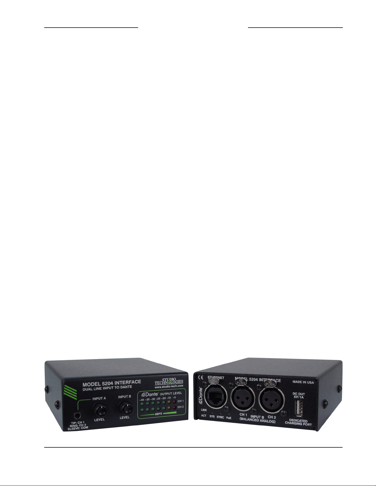
Figure 1. Model 5204 Dual Line Input to Dante Interface front and rear views
Model 5204 User Guide Issue 1, August 2014
Studio Technologies, Inc. Page 3
Page 4

Dual Line Input to Dante Interface
Model 5204
Applications
The Model 5204 is perfect for use in conjunction with a variety of fixed and portable audio
equipment that offer analog output signals.
An obvious application is with legacy equipment that only offers analog outputs. A few
simple connections are all that’s required to
covert those signals into the world of Audioover-Ethernet. When deploying, maintaining,
or modifying Dante networks the unit can
be a useful test tool, offering a simple, highquality means of creating a 2-channel signal
source. For permanent applications there’s
no reason why a Model 5204 can’t reside
within an equipment rack or be mounted,
using optional brackets, underneath a table
or on-air studio set. In a conference room
setting the unit can be permanently connected to a PoE-enabled Ethernet port, ready to
accept a signal source from various userprovided devices.
Line Input A
Using a 3-conductor (“stereo”) 3.5 mm jack,
it’s a simple matter to connect unbalanced
sources to the Model 5204’s line input A.
These signals would typically be provided
by personal computers, smartphones, or
personal audio devices which have average
(nominal) levels in the range of –20 to –10
dBu. One rotary control is used to adjust
the input level, making it a simple task to
optimize the conversion of the input analog
audio source to the Dante output. The level
knob is a push-in/push-out type which helps
prevent inadvertent adjustment.
Line Input B
The Model 5204’s line input B is designed for
use with professional line-level analog audio
signals. The 2-channel input is electronically
balanced, capacitor-coupled, and uses two
standard 3-pin female XLR connectors. A
single rotary level control allows the input
sensitivity of both channels to be adjusted.
Using the push-in/push-out knob it’s a
simple matter to adjust the input circuitry
to match average (nominal) signal levels
which would typically be in the range of
0 to +4 dBu. And with a maximum input
level of +24 dBu there will always be
sufficient headroom for “pro” audio performance. Protection components in the input
circuitry help ensure reliability in tough field
applications.
Summing (Mixing) of the Input
Signals
The two channels associated with line input
A and the two channels associated with line
input B are mixed (summed), sent to analog-to-digital conversion circuitry, and then
transmitted over the Dante network. The
two signals associated with the channel 1
(or “left”) inputs are combined and sent out
Dante channel 1. The two signals associated with the channel 2 (or “right”) inputs are
combined and sent out Dante channel 2.
(There is no provision for creating a monaural signal which is typically not an issue as
other connected Dante-enabled equipment
can usually perform such tasks.)
Metering
Two 7-step LED meters provide a real-time
level indication of the two audio output
channels. Scaled in dBFS (decibels referenced to full scale digital) the meters offer
a direct view of the signal levels as they
are transported in the digital domain via
Dante. Optimal audio performance requires
transporting signals at their proper levels
— without an accurate indication this can
be difficult to achieve.
Issue 1, August 2014 Model 5204 User Guide
Page 4 Studio Technologies, Inc.
Page 5

Dual Line Input to Dante Interface
Model 5204
Ethernet Data and PoE
The Model 5204 connects to a data network using a standard 100 Mb/s twistedpair Ethernet interface. The physical
interconnection is made by way of a
Neutrik® etherCON RJ45 connector.
While compatible with standard RJ45
plugs, etherCON allows a ruggedized and
locking interconnection for harsh or highreliability environments. An LED displays
the status of the network connection.
The Model 5204’s operating power is
provided by way of the Ethernet interface
using the Power-over-Ethernet (PoE) standard. This allows fast and efficient interconnection with the associated data network.
To support PoE power management, the
Model 5204’s PoE interface reports to the
power sourcing equipment (PSE) that it’s
a class 3 (mid power) device. An LED is
provided to indicate when power is being
supplied to the Model 5204. Note that no
provision has been made to allow an exter
nal power source to be connected. However, if the associated Ethernet switch does
not provide PoE capability a commonlyavailable mid-span PoE power injector
can be utilized.
Dedicated Charging Port
(DCP)
A unique resource is the Model 5204’s
dedicated charging port. Using a standard
USB type A receptacle, the port has a
5 volt output with a maximum current of
approximately 1 amp. This nominally
5 watt output should be sufficient to rapidly
charge a personal audio player, smartphone, or tablet device. An auto-detect feature supports divider mode, short mode,
and 1.2 V/1.2 V charging modes. Besides
charging, the port can allow a connected
device to continuously send audio to the
associated Dante network without requiring
an external power source. Note that in this
situation interfacing a device with the Model
5204 requires separate cables, one for the
analog audio source and one for powering/
charging.
One note of interest: the dedicated charging port derives its power from the Ethernet
with Power-over-Ethernet (PoE) connection. While the Model 5204’s audio and
data circuitry takes very little energy, the
dedicated charging port can source up to
approximately 5 watts. As such, the Model
5204’s Ethernet interface will identify itself
to upstream power-sourcing-equipment
(PSE), typically an Ethernet switch with
integrated PoE, as a PoE class 3 powered
device (PD).
-
Dante Audio-over-Ethernet
Audio data is sent from the Model 5204
using the Dante Audio-over-Ethernet media
networking technology. As a Dante-compliant device, the Model 5204’s two audio
channels can be assigned to other devices
using the Dante Controller software application. Bit depths of up to 24 and sample
rates of 44.1, 48, 88.2, and 96 kHz are
supported. Two bi-color LEDs provide an
indication of the Dante connection status.
The Model 5204 uses Audinate’s Ultimo™
integrated circuit for implementing Dante.
The integrated circuit’s firmware can be
updated via the Ethernet connection, helping to ensure that its capabilities remain up
to date.
Model 5204 User Guide Issue 1, August 2014
Studio Technologies, Inc. Page 5
Page 6

Dual Line Input to Dante Interface
Model 5204
Connections
In this section signal interconnections will be
made using the connectors located on the
front and back panel of the Model 5204. An
Ethernet data connection with Power-overEthernet (PoE) capability will be made using
either a standard RJ45 patch cable or an
etherCON protected RJ45 plug. Line-level
signal sources will be connected using the
3.5 mm jack associated with line input A and
the 3-pin XLR connectors associated with
line input B. The USB dedicated charging
port can be connected to power or charge
an external device.
System Components
Included in the shipping carton is a Model
5204 Interface and a printed copy of the
user guide.
Line Input A
Line input A is intended for connection
with a 2-channel (stereo) unbalanced linelevel analog audio signal source. This will
typically be associated with consumer and
semi-professional devices such as personal
audio players, AV equipment, and tablet
and personal computers. These signals
will typically have a nominal level in the
range of –15 to –10 dBu. Devices are connected to line input A by way of a 3.5 mm
3-conductor jack located on the Model
5204’s front panel. As is standard for 2channel (stereo) audio signals present on
this type of connector channel 1 (left) is
connected to the jack’s tip lead, channel 2
(right) to the jack’s ring lead, and the common connection to the jack’s sleeve.
Line Input B
Ethernet Connection
A 100BASE-TX Ethernet connection that
supports Power-over-Ethernet (PoE) is
required for Model 5204 operation. This
one connection will provide both the Ethernet data interface and power for the Model
5204’s circuitry. A 10BASE-T connection is
not sufficient and a 1000BASE-T (“GigE”)
connection is not supported unless it can
automatically “fall back” to 100BASE-TX
operation. For PoE switch (PSE) power
management the Model 5204 will enumerate
itself as a PoE class 3 device.
The Ethernet connection is made by way of
a Neutrik etherCON protected RJ45 connector that is located on the back panel of
the Model 5204. This allows connection by
way of a cable-mounted etherCON plug or
a standard RJ45 plug. The Model 5204’s
Ethernet interface supports auto MDI/MDI-X
so that most cabling implementations will be
correctly supported.
Line input B is intended for connection with
two balanced line-level analog audio signal
sources associated with professional audio
and video equipment. These will include
devices such as audio consoles, video
storage and playback systems, wireless
microphone receivers, and audio testing
equipment. The audio quality is such that
using line input B for on-air broadcast or
streaming applications would be appropriate. The two channels associated with line
input B are analog, electronically balanced,
and capacitor coupled.
The Model 5204 provides two 3-pin female
XLR connectors for interfacing signals with
line input B. Pin 2 on a mating connector
(3-pin male XLR) should be connected as
signal + (high), pin 3 as signal – (low), and
pin 1 as common/shield. With an unbalanced source connect signal + (high) to the
pin 2 and signal – (low/shield) to both pins
1 and 3.
Issue 1, August 2014 Model 5204 User Guide
Page 6 Studio Technologies, Inc.
Page 7

Dual Line Input to Dante Interface
Model 5204
USB Dedicated Charging Port
A USB type A receptacle is located on the
back panel of the Model 5204. It allows
connection to a wide variety of devices that
obtain power for operation and/or charging
via USB. No data is transferred to or from
the Model 5204 with this connector, only
power is provided. The dedicated charging port (DCP) is capable of automatically
enumerating (“handshaking”) with a number of the popular device protocols. This
allows operation with most mobile phones,
tablet computers, and personal audio devices. Using the appropriate cable, simply
connect the dedicated charging port to the
selected device. Up to 5 watts of energy
can be delivered on a continuous basis.
It’s possible that the device being powered and/or charged is also serving as the
source of analog audio for line input A. In
this case two interface cables will be used
to link the device with the Model 5204.
Dante
Configuration
Several Model 5204’s Dante-related
parameters can be configured. These
configuration settings will be stored in nonvolatile memory within the Model 5204’s
circuitry. Configuration will typically be
done with the Dante Controller software
application which is available for download
free of charge at www.audinate.com. Ver
sions of Dante Controller are available to
support Windows® and OS X® operating
systems. The Model 5204 uses the Ultimo
2-input/2-output integrated circuit to implement the Dante architecture. However, only
the two transmitter (output) channels are
utilized. This dictates which parameters
-
can be configured and what choices are
available.
The two transmitter channels associated
with the Model 5204’s Dante interface
must be assigned to the desired receiver
channels. Within Dante Controller a “sub
scription” is the term used for routing a
transmit flow (a group of output channels)
to a receive flow (a group of input channels). Note that as of the writing of this
guide the number of transmitter flows
associated with an Ultimo integrated circuit
is limited to two.
The Model 5204 will support audio sample
rates of 44.1, 48, 88.2, and 96 kHz with
a limited selection of pull-up/pull-down
values. The Model 5204 can serve as the
clock master for a Dante network but in
most cases it will “sync” to another device.
The Model 5204 has a default Dante device name of ST-M5204 and a unique suf-
fix. The suffix identifies the specific Model
5204 that is being configured (it relates to
the MAC address of the Ultimo integrated
circuit). The two Dante transmitter channels have default names of Ch1 and Ch2.
Using Dante Controller the default device
and channel names can be revised as ap
propriate for the specific application.
-
-
Operation
At this point an Ethernet connection with
Power-over-Ethernet (PoE) capability
should have been made. The unit’s Dante
configuration settings should have been
selected using Dante Controller software
application. At a minimum the Model
5204’s two Dante transmitter channels
should have been routed to receiver
channels on an associated device. Analog
Model 5204 User Guide Issue 1, August 2014
Studio Technologies, Inc. Page 7
Page 8

Dual Line Input to Dante Interface
Model 5204
signal source connections to line input A
and line input B should have been made
as desired. A device may have been connected to the USB dedicated charging
port. Normal operation of the Model 5204
can now begin.
Initial Operation
The Model 5204 will immediately begin to
function as soon as a Power-over-Ethernet
(PoE) power source is connected. At this
time the USB dedicated charging port will
become functional. However, full operation
may take up to 20 seconds to begin. Upon
initial power up the four status LEDs located on the back panel will begin to light. The
meter LEDs on the front panel will light in a
test sequence. After the meter LEDs complete their test sequence one meter LED
associated with channel 1 and one meter
LED associated with channel 2 will briefly
light to indicate the version number of the
unit’s firmware (embedded software). Once
that sequence has completed and the
Dante connection has been established
full operation will begin.
interface and associated network. The
SYS LED will light red upon Model 5204
power up to indicate that the Dante interface is not ready. After a short interval it
will light green to indicate that it is ready to
pass data with another Dante device. The
SYNC LED will light red when the Model
5204 is not synchronized with a Dante
network. It will light solid green when the
Model 5204 is synchronized with a Dante
network and an external clock source
(timing reference) is being received. It will
slowly flash green when the Model 5204 is
part of a Dante network and is serving as
a clock master.
How to Identify a Specific
Model 5204
The Dante Controller software application
offers an identify command that can be
used to help locate a specific Model 5204.
When identify is selected for a specific unit
the SYS and SYNC LEDs on that unit will
slowly flash green.
Level Meters
Ethernet, PoE, and Dante
Status LEDs
Four status LEDs are located below the
Ethernet connector on the Model 5204’s
back panel. The PoE LED will light green
to indicate that Power-over-Ethernet (PoE)
associated with the connected Ethernet
signal is providing operating power for the
Model 5204. The LINK/ACT LED will light
green whenever an active connection to
a 100 Mb/s Ethernet network has been
established. It will flash in response to data
packet activity. The SYS and SYNC LEDs
display the operating status of the Dante
Issue 1, August 2014 Model 5204 User Guide
Page 8 Studio Technologies, Inc.
Two 7-step LED meters will display the
level of the two Dante transmitter (output)
channels. The meter steps are calibrated
in dBFS which indicates the number of dB
below the maximum possible digital signal
level. The maximum level is 0 dBFS which
occurs when the digital audio data is all
“1”s. In typical applications a signal level
of –20 dBFS would be the desired nominal (normal average) value. The five meter
steps that have a threshold of –20 dBFS
and less light with the color green. The
step that lights at –15 dBFS and greater
is yellow in color and indicates a “hot” or
above average signal level. The top step
Page 9

Dual Line Input to Dante Interface
Model 5204
lights red in color when a signal levels is
–5 dBFS or greater, indicating that a potentially “clipped” (distorted due to excessive
level) signal is present.
Input A
The signal connected to the tip (left channel) connection of line input A’s 3.5 mm
jack is associated with Dante transmitter
(output) channel 1. The ring (right channel)
connection of the 3.5 mm jack is associated
with Dante transmitter channel 2. The pushin/push-out rotary control adjusts the input
level of both channels of line input A. In its
fully counterclockwise position the input
signal are essentially off (muted). Adjust
the control such that normal input signals
will cause the five green LEDs to light.
Peak signals can cause the yellow LED
to light on occasion. But the yellow LED
should never be continuously lit. The red
LED should never light, except possibly in
the case of an extreme peak. The red LED
lighting on a regular basis indicates that
the signal level is at risk of reaching digital
0 (0 dBFS) which is destructive to audio
quality.
Input B
The signal connected to line input B’s
channel 1 3-pin female XLR connector is
associated with Dante transmitter (output)
channel 1. The signal connected to line
input B’s channel 2 XLR connector is associated with Dante transmitter (output) channel 2. The push-in/push-out rotary control
adjusts the input level of both channels of
line input B. In its fully counterclockwise
position the input signals are essentially off
(muted). Adjust the control such that normal
input signals will cause the five green LEDs
to light. Peak signals can cause the yellow
LED to light on occasion. But the yellow
LED should never be continuously lit. The
red LED should never light, except possibly
in the case of an extreme peak. The red
LED lighting on a regular basis indicates that
the signal level is at risk of reaching digital
0 (0 dBFS) which is destructive to audio
quality.
Line Inputs A & B Combine
It’s important to highlight that the Model
5204’s two 2-channel line inputs (A and B)
combine in the analog domain. In effect
the Model 5204 is a dual-input 2-channel
(stereo) mixer and Dante converter. A signal present on channel 1 (left) of line input
A and a signal present on channel 1 of line
input B will combine (mix together or sum)
after (“post”) the two level controls. This
combined signal is routed to the analogto-digital converter circuitry and on to the
Dante transmitter (output) for channel 1.
A signal present on channel 2 (right) of line
input A and a signal present on channel 2
of line input B will combine (mix together
or sum) after (“post”) the two level controls.
This combined signal is routed to the analog-to-digital converter circuitry and on to
the Dante transmitter (output) for channel
2. But note that no monaural version of the
input signals is created.
USB Dedicated Charging Port
There are no special instructions when using
the dedicated charging port. Simply connect
the desired device and the function will typically automatically start. The only limitations
will be with the port’s 5 volt, 1 ampere (5
watt) maximum power supply capability.
A connected device that requires more
energy for operation may not enumerate
(handshake or negotiate) successfully. No
damage will occur in this case.
Model 5204 User Guide Issue 1, August 2014
Studio Technologies, Inc. Page 9
Page 10

Dual Line Input to Dante Interface
Model 5204
There are no LEDs or performance indicators or configuration settings associated
with the dedicated charging port. It’s really
just a “plug-in and go” feature.
Technical Notes
Ultimo Firmware Update
The Model 5204 implements Dante connectivity using the Ultimo integrated circuit
from Audinate. This 2-input/2-output device can be updated by way of the Model
5204’s Ethernet connection. As of the date
of writing this guide it’s not evident as to
whether or not newer firmware will ever
need to be loaded.
Identifying the Firmware
Version Number
As previously discussed in this guide,
upon power up the meter LEDs are used
to briefly display the version number of
the Model 5204’s firmware (embedded
software). This information is typically only
necessary when working with the factory on support issues. The meter LEDs
will first go through a display sequence
followed by an approximately 1-second
period where the version number will be
indicated. The top row of seven LEDs will
display the major version number with a
range of 1 to 7. The bottom row of seven
LEDs will display the minor version number
with a range of 1 to 7. Refer to Figure 2 for
details.
Major Version Number
1 2 3 4 5 6 7
O O O O O O
O O O O O O
.1 .2 .3 .4 .5 .6 .7
Minor Version Number
Figure 2. Detail of front panel showing the LEDs that display the firmware version.
In this example, the version shown is 1.1.
Issue 1, August 2014 Model 5204 User Guide
Page 10 Studio Technologies, Inc.
Page 11

Dual Line Input to Dante Interface
Model 5204
Specifications
Network Audio Technology:
Type: Dante Audio-over-Ethernet
Bit Depth: up to 24
Sample Rates: 44.1, 48, 88.2, and 96 kHz
Network Interface:
Type: twisted-pair Ethernet with Power-over-
Ethernet (PoE)
Data Rate: 100 Mb/s (10 Mb/s Ethernet not
supported)
Power: Power-over-Ethernet (PoE) per IEEE 802.3af
class 3 (mid power,
General Audio Parameters:
Frequency Response: 20 Hz to 20 kHz, ±0.5 dB,
line input B to Dante
Distortion (THD+N): 0.01%, measured at 1 kHz,
+4 dBu, line input B to Dante
Dynamic Range: >100 dB, A-weighted, line input B
to Dante
Line Input A:
Type: 2-channel (“stereo”) unbalanced, capacitor-
coupled
Input Impedance: 10 k ohms
Nominal Level: adjustable using rotary level control,
–3 dBu @ 100% rotation
Maximum Level:
≤12.95 watts)
+10 dBu
Line Input B:
Type: 2-channel (“stereo”) electronically balanced,
capacitor-coupled
Input Impedance: 20 k ohms
Nominal Level: adjustable using rotary level
control, +11 dBu @ 100% rotation
Maximum Level: +24 dBu
Meters:
Function: displays level of Dante output signals
Type: 7-segment LED, modified VU ballistics
Dedicated Charging Port:
Function: powering and charging of connected
devices; no data interface
Output (Nominal): 5 volts DC, 1 amp (5 watts)
Compatibility: auto-detect supports divider mode,
short mode, and 1.2 V/1.2 V charging modes
Connectors:
Ethernet: Neutrik etherCON RJ45
Line Input A: 3-conductor (“stereo”) 3.5 mm jack
Line Input B: 2, 3-pin female XLR
Dedicated Charging Port: USB type A receptacle
Dimensions (Overall):
4.2 inches wide (10.7 cm)
1.7 inches high (4.3 cm)
5.1 inches deep (13.0 cm)
Mounting Option: bracket kit
Weight:
2
0.8 pounds (0.35 kg)
Specifications subject to change without notice.
Model 5204 User Guide Issue 1, August 2014
Studio Technologies, Inc. Page 11
 Loading...