

Page 1

Model 5202
Dante™ to Phones and Line Output Interface
User Guide
Issue 1, August 2014
This User Guide is applicable for serial numbers
M5202-00151 and later
Copyright © 2014 by Studio Technologies, Inc., all rights reserved
www.studio-tech.com
50276-0814, Issue 1
Page 2

Table of Contents
Introduction ................................................................... 3
Connections .................................................................. 5
Dante Configuration ...................................................... 6
Operation ...................................................................... 6
Technical Notes ............................................................ 8
Specifications ............................................................... 9
Page 3
Dante to Phones and Line Output Interface
Model 5202
Introduction
The Model 5202 Interface is a generalpurpose audio device that supports
applications utilizing the Dante™ Audioover-Ethernet media networking technology.
Two Dante-associated audio channels can
be assigned to the Model 5202 which provides headphone and balanced line-level
outputs. The audio quality is such that
virtually any audio application can be supported, from simple headphone or loudspeaker monitoring to interfacing with
high-performance on-air broadcast, stadium
AV, or corporate audio systems. Multi-step
LED meters provide confirmation of the level
of the two input audio channels. The compact, lightweight design allows the Model
5202 to be used in portable or desktop situ
ations or deployed as a permanent solution
in fixed applications. Standard connectors
ensure fast, reliable deployment. The unit
requires only an Ethernet connection to
supply both the data interface as well as
Power-over-Ethernet (PoE) power.
Applications
The Model 5202 is perfect for use in conjunction with the Dante Controller software
application. Driving a pair of headphones
or set of amplified speakers, audio flows
and associated channels can be quickly
-
confirmed for content as well as signal level.
For field applications the unit can serve
as both a test tool and a general-purpose
source of analog audio outputs. With level
controls associated with both the headphone and line outputs interfacing with
virtually any analog audio input is a simple
matter. For permanent applications there’s
no reason why a Model 5202 can’t reside
within an equipment rack or be mounted,
using optional brackets, underneath a table
or on-air studio set. The low-power circuitry
is intended for continuous operation.
Headphone Output
A sonically-excellent 2-channel (stereo)
headphone output is provided. It is capable
of driving contemporary headphones, headsets, and earbuds to substantial levels at
very low distortion. A rotary control is used
to adjust the headphone output level. The
level knob is a push-in/push-out type which
helps prevent inadvertent adjustment. For
flexibility the headphone output is provided
on two separate 3-conductor jacks: a 3.5
mm on the front panel and a ¼-inch on the
back. The audio quality of the headphone
output is such that it can also be used as a
2-channel unbalanced line output. The output level control will make it a simple task
to optimally interface the headphone output
with inputs on personal computers, portable
audio devices, and “semi-pro” equipment.
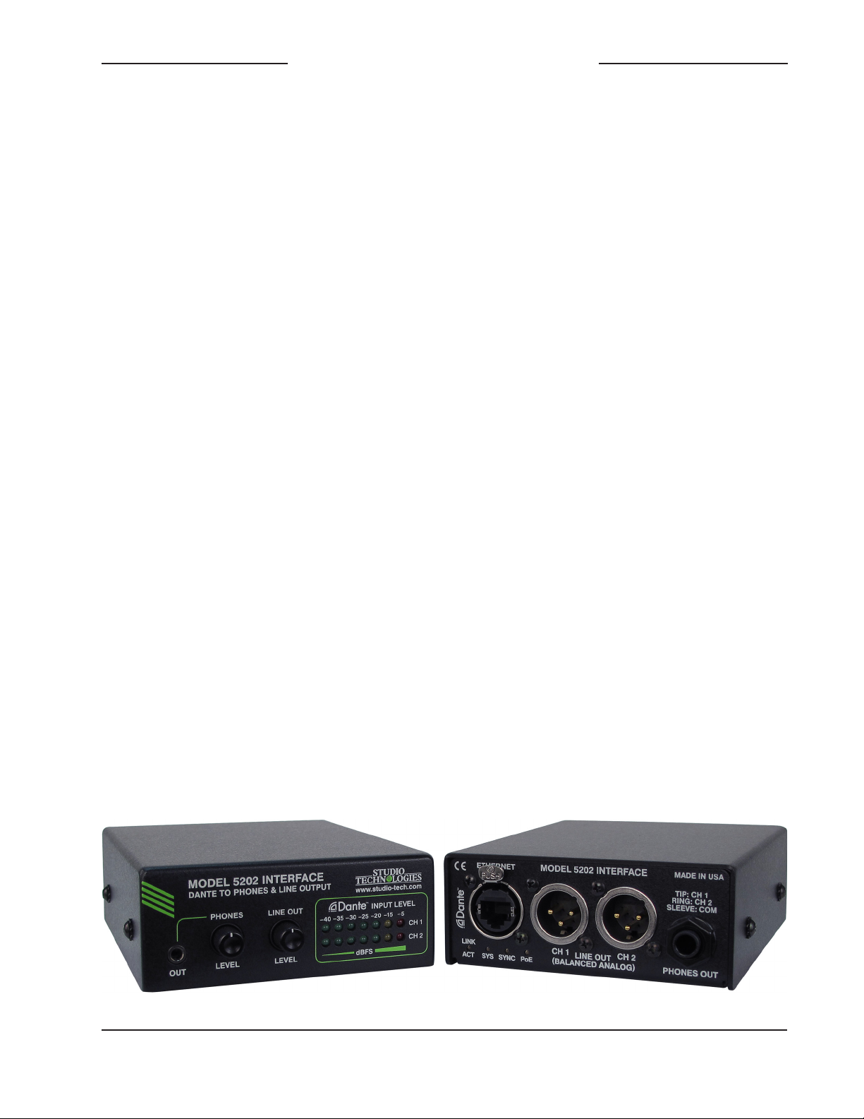
Figure 1. Model 5202 Dante to Phones and Line Output Interface front and rear views
Model 5202 User Guide Issue 1, August 2014
Studio Technologies, Inc. Page 3
Page 4

Dante to Phones and Line Output Interface
Model 5202
Line Outputs
The Model 5202 provides a 2-channel
line-level, electronically-balanced analog
audio output by way of standard 3-pin male
XLR connectors located on the back panel.
A rotary level control allows the nominal
(average) level of the line outputs to be
adjusted. Using the push-in/push-out knob
it’s a simple matter to achieve the desired
nominal output levels which include –10,
0, or +4 dBu. And with a maximum output level of +24 dBu there will always be
sufficient headroom for “pro” audio per
formance. Protection components in the
output circuitry help ensure reliability in
field applications.
The line outputs can serve a number of
monitoring and interfacing uses. Audio
amplifiers or amplified speakers can be
directly connected. The level control can be
used to adjust the speaker volume or used
as a level trim function to match the speaker’s input sensitivity. The line outputs can
also serve as a source for interfacing with
analog inputs on audio consoles, wireless
in-ear or IFB monitor systems, as well as
audio recording devices. The level control
will help to ensure that the nominal level
of the line outputs will match the requirements of the connected equipment.
-
Metering
Two 7-step LED meters provide a real-time
level indication of the two Dante-supplied
audio channels. Scaled in dBFS (decibels
referenced to full scale digital) the meters
offer a direct view of the signal levels as
they arrive in the digital domain. Optimal
audio performance requires transporting
signals at their proper levels — without an
accurate indication this can be difficult to
achieve.
Ethernet Data and PoE
The Model 5202 connects to a data network
using a standard 100 Mb/s twisted-pair
Ethernet interface. The physical interconnection is made by way of a Neutrik®
etherCON RJ45 connector. While compatible with standard RJ45 plugs, etherCON
allows a ruggedized and locking intercon
nection for harsh or high-reliability environments. An LED displays the status of the
network connection.
The Model 5202’s operating power is provided by way of the Ethernet interface using
the Power-over-Ethernet (PoE) standard.
This allows fast and efficient interconnection with the associated data network. To
support PoE power management the Model
5202’s PoE interface reports to the power
sourcing equipment (PSE) that it’s a class 1
(very low power) device. An LED is provided
to indicate when power is being supplied
to the Model 5202. Note that no provision
has been made to allow an external power
source to be connected. However, if the
associated Ethernet switch does not provide
PoE capability a commonly-available midspan PoE power injector can be utilized.
-
Dante Audio-over-Ethernet
Audio data is sent to the Model 5202
using the Dante Audio-over-Ethernet
media networking technology. As a Dantecompliant device, two audio channels can
be assigned to the unit using the Dante
Controller software application. A single
mouse-click is all that’s required to route
an audio signal to the Model 5202. Bit
depths of up to 24 and sample rates of
44.1, 48, 88.2, and 96 kHz are supported.
Two bi-color LEDs provide an indication of
the Dante connection status. The Model
5202 uses Audinate’s Ultimo™ integrated
Issue 1, August 2014 Model 5202 User Guide
Page 4 Studio Technologies, Inc.
Page 5

Dante to Phones and Line Output Interface
Model 5202
circuit for implementing Dante. The integrated circuit’s firmware can be updated via the
Ethernet connection, helping to ensure that
its capabilities remain up to date.
Connections
In this section signal interconnections will
be made using the connectors located on
the front and back panel of the Model 5202.
An Ethernet data connection with Powerover-Ethernet (PoE) capability will be made
using either a standard RJ45 patch cable
or an etherCON protected RJ45 plug.
Headphones can be connected using either
the 3.5 mm or ¼-inch 3-conductor phone
jack. Line output connections are made
using two 3-pin male XLR connectors.
System Components
Included in the shipping carton are a Model
5202 Interface and printed copy of the user
guide.
Ethernet Connection
A 100BASE-TX Ethernet connection that
supports Power-over-Ethernet (PoE) is
required for Model 5202 operation. This
one connection will provide both the Ether
net data interface and power for the Model
5202’s circuitry. A 10BASE-T connection is
not sufficient and a 1000BASE-T (“GigE”)
connection is not supported unless it can
automatically “fall back” to 100BASE-TX
operation. For PoE switch (PSE) power
management the Model 5202 will enumer
ate itself as a PoE class 1 device.
The Ethernet connection is made by way
of a Neutrik etherCON protected RJ45 connector that is located on the back panel of
the Model 5202. This allows connection by
way of a cable-mounted etherCON plug or
-
-
a standard RJ45 plug. The Model 5202’s
Ethernet interface supports auto MDI/MDI-X
so that most cabling implementations will be
correctly supported.
Headphone Output
The Model 5202’s headphone output is
compatible with standard stereo headphones, headsets, or earbuds. Connecting
devices with a nominal impedance of 100
ohms or greater is recommended. But this
shouldn’t be an issue since essentially all
of the contemporary devices meet this
recommendation.
Devices are connected to the headphone
output by way of either a 3.5 mm 3-conductor jack located on the Model 5202’s front
panel or a ¼-inch 3-conductor phone jack
located on the Model 5202’s back panel.
As is standard for stereo headphones, the
left channel is connected to the jacks’ tip
lead, the right channel to the jacks’ ring
lead, and the common connection to the
jacks’ sleeve. Inside the Model 5202 the
connections on the two jacks are wired in
parallel (“multed”); the same output circuitry
drives both connectors. While it’s expected
that typically only one pair of headphones
or earbuds will be connected at a time,
there is no reason why two pairs can’t be
connected at the same time.
Line Outputs
The line outputs are designed for generalpurpose use which could include connecting to inputs on audio consoles, amplified
speakers, audio storage devices or systems, or transmitters associated with wireless in-ear monitors. The audio quality is
such that using the line outputs for on-air
broadcast or streaming applications would
be appropriate. The line outputs are analog,
Model 5202 User Guide Issue 1, August 2014
Studio Technologies, Inc. Page 5
Page 6

Dante to Phones and Line Output Interface
Model 5202
electronically balanced, capacitor coupled,
and will perform optimally when driving
loads of 2 k (2000) ohms or greater. The
nominal output level depends on the setting
of the rotary level control. When the control
is set to its fully clockwise position the nominal level is +4 dBU. This means that if there
is a Dante transmitter (output) channel that
has a nominal level of –20 dBFS, when it’s
routed to a Model 5202 the associated line
output will have a nominal level of +4 dBu.
The Model 5202 provides two 3-pin male
XLR connectors for interfacing with associated equipment. Pin 2 should be connected
as signal + (high), pin 3 as signal – (low),
and pin 1 as common/shield. To connect
to an unbalanced load use pin 2 as signal
+ (high) and pin 1 as low/shield. Pin 3
should be left unconnected. To clarify, for
correct unbalanced operation it is important
not to connect pin 3 to anything; do not
connect pins 1 and 3 together.
Dante
which parameters can be configured and
what choices are available.
The two audio input channels associated
with the Model 5202’s Dante interface must
be assigned to the desired output sources.
Within Dante Controller a “subscription” is
the term used for routing a transmit flow
(a group of output channels) to a receive
flow (a group of input channels). The Model
5202 will support audio sample rates of
44.1, 48, 88.2, and 96 kHz with a limited
selection of pull-up/pull-down values. The
Model 5202 can serve as the clock master
for a Dante network but in most cases it will
“sync” to another device.
The Model 5202 has a default Dante device
name of ST-M5202 and a unique suffix.
The suffix identifies the specific Model
5202 that is being configured (it relates
to the MAC address of the Ultimo integrated circuit). The two Dante receiver channels have default names of Ch1 and Ch2.
Using Dante Controller the default device
and channel names can be revised as
appropriate for the specific application.
Configuration
Several Model 5202’s Dante-related parameters can be configured. These configuration settings will be stored in non-volatile
memory within the Model 5202’s circuitry.
Configuration will typically be done with the
Dante Controller software application which
is available for download free of charge at
www.audinate.com. Versions of Dante Controller are available to support Windows®
and OS X® operating systems. The Model
5202 uses the Ultimo 2-input/2-output
integrated circuit to implement the Dante
architecture. However only the two receiver
(input) channels are utilized. This dictates
Issue 1, August 2014 Model 5202 User Guide
Page 6 Studio Technologies, Inc.
Operation
At this point an Ethernet connection with
Power-over-Ethernet (PoE) capability
should have been made. The unit’s Dante
configuration settings should have been
made using Dante Controller software
application. At a minimum a transmitter
source should have been routed to the
Model 5202’s two Dante receiver channels.
Headphone and line output connections
should have been made as desired.
Normal operation of the Model 5202
can now begin.
Page 7

Dante to Phones and Line Output Interface
Model 5202
Initial Operation
The Model 5202 will immediately begin to
function after a Power-over-Ethernet (PoE)
power source is connected. However, full
operation may take up to 20 seconds to
begin. Upon initial power up the four status
LEDs located on the back panel will begin
to light. The meter LEDs on the front panel
will light in a test sequence. After the meter
LEDs complete their test sequence one
meter LED associated with channel 1 and
one meter LED associated with channel
2 will briefly light to indicate the version
number of the unit’s firmware (embedded
software). Once that sequence has completed and the Dante connection has been
established audio signals can be available.
Ethernet, PoE, and Dante
Status LEDs
Four status LEDs are located below the
Ethernet connector on the Model 5202’s
back panel. The PoE LED will light green
to indicate that Power-over-Ethernet (PoE)
associated with the connected Ethernet
signal is providing operating power for the
Model 5202. The LINK/ACT LED will light
green whenever an active connection to
a 100 Mb/s Ethernet network has been
established. It will flash in response to data
packet activity. The SYS and SYNC LEDs
display the operating status of the Dante
interface and associated network. The SYS
LED will light red upon Model 5202 power
up to indicate that the Dante interface is
not ready. After a short interval it will light
green to indicate that it is ready to pass
data with another Dante device. The SYNC
LED will light red when the Model 5202 is
not synchronized with a Dante network. It
will light solid green when the Model 5202
is synchronized with a Dante network and
an external clock source (timing reference)
is being received. It will slowly flash green
when the Model 5202 is part of a Dante
network and is serving as a clock master.
How to Identify a Specific
Model 5202
The Dante Controller software application
offers an identify command that can be
used to help locate a specific Model 5202.
When identify is selected for a specific unit
the SYS and SYNC LEDs on that unit will
slowly flash green.
Level Meters
Two 7-step LED meters will display the level of the two Dante audio receiver (input)
channels. The meter steps are calibrated
in dBFS which indicates the number of dB
below the maximum possible digital signal
level. The maximum level is 0 dBFS which
occurs when the digital audio data is all
“1”s. In typical applications a signal level
of –20 dBFS would be the nominal (normal
average) value. The five meter steps that
have a threshold of –20 dBFS and less
light with the color green. The step that
lights at –15 dBFS and greater is yellow
in color and indicates a “hot” or above
average signal level. The top step lights
red in color when a signal level is –5 dBFS
or greater, indicating that a potentially
“clipped” (distorted due to excessive level)
signal is present.
Headphone Output
Dante input channel 1 is routed to the left
headphone output channel. This signal is
connected to the tip connection on both
the 3.5 mm and ¼-inch headphone output
Model 5202 User Guide Issue 1, August 2014
Studio Technologies, Inc. Page 7
Page 8

Dante to Phones and Line Output Interface
Model 5202
jacks. Dante input channel 2 is routed to
the right headphone output channel which
is associated with the ring connection on
the output jacks. The push-in/push-out
headphone level control adjusts the level of
both the left and right channels of the headphone outputs. In the fully counterclockwise
position the output level is essentially off.
Care must be taken when adjusting the
headphone output level control. The output
circuitry is capable of driving headphones,
headsets, or earbuds to damaging levels.
Hearing damage is a real possibility and
caution must be exercised.
Technical Notes
Ultimo Firmware Update
The Model 5202 implements Dante connectivity using the Ultimo integrated circuit from
Audinate. This 2-input/2-output device can
be updated by way of the Model 5202’s
Ethernet connection. As of the date of writing this guide it’s not evident as to whether
or not newer firmware will ever need to be
loaded.
Identifying the Firmware
Version Number
Line Outputs
Dante input channel 1 is routed to line
output channel 1. Dante input channel 2 is
routed to line output channel 2. The associated push-in/push-out rotary control adjusts
the level of both line output channels. In its
fully counterclockwise position the output
level of the two channels are essentially
off. In its fully clockwise position the output
levels will be approximately +4 dBu with
a Dante input signal that has a level of
–20 dBFS.
As previously discussed in this guide,
upon power up the meter LEDs are used
to briefly display the version number of
the Model 5202’s firmware (embedded
software). This information is typically only
necessary when working with the factory on
support issues. The meter LEDs will first go
through a display sequence followed by an
approximately 1-second period where the
version number will be indicated. The top
row of seven LEDs will display the major
version number with a range of 1 to 7. The
bottom row of seven LEDs will display the
minor version number with a range of 1
to 7. Refer to Figure 2 for details.
Major Version Number
1 2 3 4 5 6 7
O O O O O O
O O O O O O
.1 .2 .3 .4 .5 .6 .7
Minor Version Number
Figure 2. Detail of front panel showing the LEDs that display the firmware version.
In this example, the version shown is 1.1.
Issue 1, August 2014 Model 5202 User Guide
Page 8 Studio Technologies, Inc.
Page 9

Dante to Phones and Line Output Interface
Model 5202
Specifications
Network Audio Technology:
Type: Dante Audio-over-Ethernet
Bit Depth: up to 24
Sample Rates: 44.1, 48, 88.2, and 96 kHz
Network Interface:
Type: twisted-pair Ethernet with Power-over-
Ethernet (PoE)
Data Rate: 100 Mb/s (10 Mb/s Ethernet not
supported)
Power: Power-over-Ethernet (PoE) per IEEE
802.3af class 1 (very low power,
General Audio Parameters:
Frequency Response: 20 Hz to 20 kHz, ±0.5 dB,
Dante to line output
Distortion (THD+N): 0.01%, measured at 1 kHz,
+4 dBu, Dante to line output
Dynamic Range: >100 dB, A-weighted, Dante to
line output
≤3.84 watts)
Line Outputs: 2
Type: electronically balanced, capacitor-coupled,
intended to drive balanced or unbalanced loads of
2 k ohms or greater
Source Impedance: 200 ohms
Nominal Level: adjustable using rotary level control,
+4 dBu @ 100% rotation
Maximum Level: +24 dBu into 2 k ohms
Meters:
Function: displays level of Dante input signals
Type: 7-segment LED, modified VU ballistics
Connectors:
Ethernet: Neutrik etherCON RJ45
Headphone Output: 3.5 mm and ¼-inch
3-conductor jacks
Line Outputs: 3-pin male XLR
Dimensions (Overall):
4.2 inches wide (10.7 cm)
1.7 inches high (4.3 cm)
5.1 inches deep (13.0 cm)
2
Headphone Output:
Type: stereo, configured to drive headphones
through 100 ohm series resistors
Compatibility: intended for connection to headphones with impedance of 100 ohms or greater
Level: adjustable using rotary level control
Maximum Voltage: 8 Vpp, 100 ohm load
Mounting Option: bracket kit
Weight: 0.8 pounds (0.35 kg)
Specifications subject to change without notice.
Model 5202 User Guide Issue 1, August 2014
Studio Technologies, Inc. Page 9
 Loading...