

Page 1

Model 5150
Video Generator Module
User Guide
Issue 1, June 2013
This User Guide is applicable for
Model 5150 modules with the following order codes:
M5150, M5150-01, M5150-02, M5150-03X, and M5150-04X
with serial numbers 00151 and later
and firmware versions
MCU 1.3 (m5150.s19) and FPGA 1.2 (m5150.bit)
Copyright © 2013 by Studio Technologies, Inc., all rights reserved
www.studio-tech.com
50184-0613, Issue 1
Page 2

This page intentionally left blank.
Page 3

Video Generator Module
Model 5150
Table of Contents
Introduction ................................................................... 5
Installation .................................................................... 7
Configuration ................................................................ 11
Operation ...................................................................... 13
Technical Notes ............................................................ 16
Specifications ............................................................... 22
Appendix A—Model 5150 Versions .............................. 23
Appendix B—DC Input/Data Interconnection Details ... 24
Appendix C—Model 5150 Front Panel and
Printed Circuit Board (PCB) Dimensions ...................... 26
Model 5150 User Guide Issue 1, June 2013
Studio Technologies, Inc. Page 3
Page 4

Video Generator
Model 5150
Module
This page intentionally left blank.
Issue 1, June 2013 Model 5150 User Guide
Page 4 Studio Technologies, Inc.
Page 5
Video Generator Module
Model 5150
Introduction
The Model 5150 Video Generator Module
is a unique device suited for a variety of
custom broadcast, post-production, industrial, and corporate multimedia installations. As a member of the 5100-Series
of modules, the Model 5150’s compact
size belies its powerful video feature set.
Advanced circuitry within the Model 5150
supports the generation of a broadcaststandard high-definition SDI signal. And
rather than reproducing a fixed test pattern, the Model 5150 has the capability
to store and output two custom video
images. The images, one for “720” and
one for “1080,” are based on bitmap (.bmp)
files that can be created using a personal
computer’s graphics program.
For convenience, the .bmp files are loaded
into the module’s nonvolatile memory via a
standard USB flash drive. The appropriate
“720” or “1080” image is automatically connected to the SDI output whenever an SDI
input signal is not present. This ensures
that an SDI output signal is always sent to
equipment further along the signal chain.
The Model 5150’s video signal generation
capability can be extremely useful, serving as both a “keep-alive” signal as well as
allowing a detailed graphics image to be
displayed for identification purposes. To
clarify, when a valid HD- or 3G-SDI signal
is connected to the module’s input it will
pass through, unchanged, to the module’s
SDI output. Only when an input is not present will the custom image be generated.
The format and rate of the custom image
will match that of the previously-connected
SDI input signal. This “learning” capability allows a Model 5150 to automatically
adapt to the SDI format and rate utilized
by a specific facility or application.
General Highlights
Applications for the Model 5150 include
sports broadcasting booth packages,
“POV” (point-of-view) remote-controlled
camera systems, stadium video interface
(I/O) locations, and government/corporate
facilities. The module’s performance is
completely “pro” with video quality, reliability, and installation flexibility matching that
of much larger-scale equipment.
For operation the Model 5150 only requires connection of a few signals. These
consist of SDI inputs and outputs, an
external source of nominal 12 volts DC
and, optionally, two wires associated with
a local RS-485 data bus. Coaxial SDI input
and output support is standard. Optical
input and output support is optional. The
acceptable DC input voltage range is 10 to
18, allowing a variety of power sources to
be utilized.
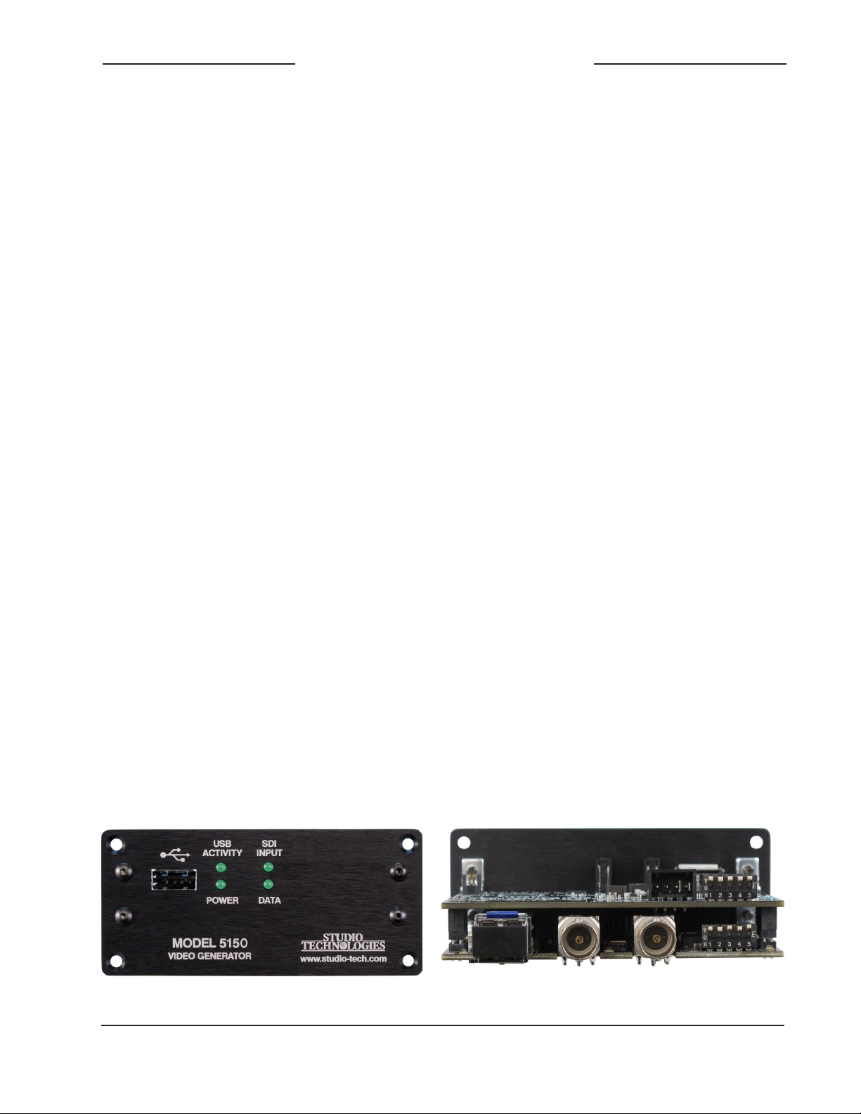
Figure 1. Model 5150 Video Generator Module front and rear views
Model 5150 User Guide Issue 1, June 2013
Studio Technologies, Inc. Page 5
Page 6

Video Generator
Model 5150
Module
The Model 5150 uses standard connectors
for fast, convenient interfacing. Coaxial
SDI input and output signals use BNC connectors. An optional video SFP fiber optic
module can be installed at the factory. The
module supports interconnection of singlemode optical fibers using LC plugs. The DC
power input and data bus connections use
a 4-position, 0.1-inch header. Low-cost IDC
(insulation-displacement connector) mating
sockets allow simple interconnection with a
variety of wire gauges. Four status LEDs
offer users both performance confidence
and troubleshooting assistance.
The Model 5150 is compatible with the
Studio Technologies’ Model 5190 Remote
Access Module. This will allow remote
monitoring and control, via an Ethernet
connection, of key module operating and
status parameters. A local RS-485 data bus
allows up to 16 of the 5100-Series modules
to be connected to a Model 5190.
Several switches are accessible during
installation and allow configuration of key
operating parameters. Updating the Model
5150’s firmware (embedded software) is
possible using a USB flash drive loaded
with personal-computer-compatible files.
Model 5150 Video Generator Modules do
not include a mounting enclosure or chassis. They are intended for mounting in custom 19-inch rack panels, equipment boxes,
broadcast furniture, “NEMA” I/O boxes, or
other specialized enclosures. It is expected
that integration firms will create applications
that use Model 5150 modules as part of
complete broadcast, production, corporate,
and government solutions. Sophisticated
users will be able to easily create “one-off”
solutions to solve unique challenges.
SDI Inputs and SDI Outputs
High-definition SMPTE-compatible SDI signals with data rates of 1.485 Gb/s nominal
(HD-SDI) and 2.97 Gb/s nominal (3G-SDI)
can be connected. Virtually all of the commonly-utilized “720” and “1080” formats are
supported. Standard-definition SDI signals
with a data rate of 270 Mb/s nominal (SDSDI) are not supported. It was felt that
users looking for advanced solutions such
as provided by the Model 5150 will not typically be working with SD-SDI signals. But
be assured that many HD-SDI and 3G-SDI
formats and rates are supported, allowing
the Model 5150 to be appropriate for worldwide use.
Coaxial (BNC) Support
Using standard BNC connectors, the Model
5150 supports one coaxial SDI input and
one coaxial SDI output.
Optical Fiber Support
Factory-implemented options allow the
Model 5150 to support SDI signals that
are transported using single-mode optical
fibers. Using video SFP modules a range
of optical input, output, and transceiver
capabilities can be supported. For a list
of available Model 5150 versions refer
to Appendix A.
The standard 1310 nanometer optical
transmit wavelength is available, as are the
more-esoteric CWDM wavelengths. When
a Model 5150 has been provided with an
optical SDI input from the factory a configuration choice selects whether it, or the
coaxial (BNC) input, is active. A module that
includes an optical SDI output will always
have its optical output active, transporting
the same SDI data as that present on the
coaxial (BNC) output.
Issue 1, June 2013 Model 5150 User Guide
Page 6 Studio Technologies, Inc.
Page 7

Video Generator Module
Model 5150
Video Generation Capability
During typical operation an HD- or 3G-SDI
signal is connected to the Model 5150’s
SDI input. It’s then “passed through” to the
module’s SDI output and on to the next
part of the signal chain. But what happens
when the external SDI signal is not present? That’s when the Model 5150’s internal
SDI generator becomes active. When a
signal is not present on the SDI input the
module will generate a high-definition
(HD- or 3G-SDI) image that will serve as
a “slate,” ID, or “SDI-active” signal.
From the factory two bitmap (.bmp) image
files are stored in nonvolatile memory. One
file is used for generating the image for
1280 x 720 pixel formats and the other for
1920 x 1080 pixel formats. But alternate
bitmap image files can be created and
stored in the Model 5150. These alternate
images can supply site- or applicationspecific information useful to “downstream”
users. Using a personal-computer graphics program, such as Microsoft® Paint® or
Adobe® Photoshop®, generating custom
images and storing them in the appropriate
bitmap format is a simple matter.
A USB port, located on the Model 5150’s
front panel, allows direct connection of
a standard USB flash drive. If the Model
5150’s firmware (embedded software)
recognizes compatible FAT32 bitmap
(.bmp) files on the USB flash drive they will
be automatically loaded into nonvolatile
memory. The USB flash drive can then be
removed with the custom images safely
stored within the Model 5150.
the Model 5150 will output a few seconds
of solid-gray color before the stored image appears. This will help to ensure that
technicians or operators will be visually
“warned” that the module’s input signal
has been lost and that the custom image
will soon be taking its place. It’s hoped
that the gray video image will be innocuous for on-air viewers yet different enough
to encourage operators to switch the
module’s output away from being “on air.”
A unique feature of the Model 5150 is its
ability to automatically adapt to the format
and rate of a connected SDI signal. This
allows the custom image to be output at
the same format and rate as that used by
the associated network, local facility, or
event. If, for example, a connected input
is “1080i/59.94” then the Model 5150 will
automatically detect and store that information. From then on whenever an SDI
input signal is not present the internal
generator will output the custom image at
“1080i/59.94.” Changing the format and
rate of the generator only requires connection of an SDI signal with the desired
characteristics. (A minimum required connection time helps to ensure that an accidental format/rate change won’t occur.)
However, there may be situations where
maintaining the format and rate of the
internally-generated signal is important.
To support this condition one configuration
choice allows the automatic format/rate
selection function to be disabled.
Installation
One subtle but important feature has
been included for situations where the
Model 5150’s output is used in on-air
broadcast applications. When a signal
is removed from the module’s SDI input,
Model 5150 User Guide Issue 1, June 2013
Studio Technologies, Inc. Page 7
Integration of the Model 5150 into a selected application should prove quite simple,
only connecting SDI input and output
signals as well as DC power is required.
Page 8

Video Generator
Model 5150
Module
Some applications will also require connection to the module’s data bus. The coaxial
(BNC) input and output connections are
compatible with most HD-SDI and 3G-SDI
signals. If the specific Model 5150 being
installed also includes optical support one
or two single-mode fiber interconnections
will be made. The fiber connections utilize
miniature LC plugs.
The DC power source is nominal 12 volts
with an acceptable range of 10 to 18 volts.
It’s possible that the module will be part of
a local RS-485 data bus that’s associated
with a Studio Technologies’ Model 5190
Remote Access Module. If so, two additional
wires are required to connect the module
to the data bus. After the connections have
been completed the module can then be
secured into the designated mounting
location.
Coaxial (BNC) SDI Output
The Model 5150 provides an SDI output
that utilizes a broadcast-standard BNC
socket. This output is referred to as the
coaxial (BNC) SDI output. Refer to Figure 2
for a detailed view of the connector’s location on the rear of the module. The coaxial
(BNC) output, depending on operating
conditions, will be either an SMPTE-compli
ant HD-SDI (1.485 Gb/s nominal) or 3GSDI (2.97 Gb/s nominal) signal. The exact
format/rate combinations supported by the
Model 5150 are listed in the Specifications
section of this guide.
Coaxial (BNC) SDI Input
An SDI source can be connected to the
Model 5150 by way of a broadcast-standard
BNC connector. This is referred to as the
coaxial (BNC) SDI input. Refer to Figure 2
for a detailed view of the connector’s
location on the rear of the module. The
coaxial (BNC) input is compatible with
SMPTE-compliant HD (1.485 Gb/s nominal) and 3G (2.97 Gb/s nominal) SDI
signals. It is not compatible with standard
definition SD-SDI (270 Mb/s nominal) signals. The exact format/rate combinations
supported by the Model 5150 are listed in
the Specifications section of this guide.
A configuration switch setting must be
made for the coaxial (BNC) SDI input to be
active. Refer to the Configuration section of
this guide for details.
Optical SDI Output
This section applies only when the specific
Model 5150 module being installed was
configured at the factory to provide an optical output. A video SFP (small form-factor
pluggable) optical module is used to provide the optical SDI output. A range of SFP
modules can be installed in the “cage” at
the back of the Model 5150. These include
transceiver modules that have both an
optical output (transmitter) and an optical input (receiver), as well as output-only
(transmitter) modules. The technical char
acteristics of the optical output will depend
on the specific module installed. The most
common transceiver or output-only SFP
module used in the Model 5150 will have
an FP (Fabry-Perot) laser emitting “light” at
a wavelength of 1310 nanometers. Other
modules can utilize a higher-performance
DFB (distributed feedback) laser that is
manufactured to produce light at one of
the 18 CWDM wavelengths. (For broadcast
applications, the common first-utilized
CWDM wavelengths are often 1490 and
1550 nanometers.)
-
Issue 1, June 2013 Model 5150 User Guide
Page 8 Studio Technologies, Inc.
Page 9
Video Generator Module
Model 5150
An LC plug terminated on a single-mode
optical fiber is used to mate with the SFP’s
optical output. When referenced to the
front of an SFP transceiver or output-only
SFP module the optical output is located
on the SFP module’s left side. To indicate
the optical output port a graphic arrow icon
pointing “out” may be present on the top of
the module. Refer to Figure 2 for a detailed
view. When terminating the LC plug with
the socket on the SFP module be certain
that the plastic plug’s locking tab is fully en
gaged into the slot of the SFP module. This
will help prevent the LC plug from becoming disconnected due to physical stress or
vibration on the fiber. Also ensure that the
end (“face”) of the plug’s ferrule has been
cleaned using appropriate methods.
Note that as of the time this user guide
was written the Model 5150 supports only
single-mode optical cable. Contact Studio
Technologies should support for multimode fiber be required.
The Model 5150 module should remain
without power whenever its optical output
has not been terminated. This ensures that
the optical energy will not project into free
space and possibly into the eyes of installation personnel. The optical output power
of video SFP modules selected by Studio
Technologies adheres to the class 1 laser
standard. As such, they do not emit sufficient power to be considered hazardous.
But best safety practices require that the
-
optical output port and all unconnected
fiber ends not be directly viewed.
No configuration switches or other settings are required to activate the optical
output. It is always active and will contain
the same SDI data as that found on the
coaxial (BNC) output. As such there is no
problem in simultaneously connecting to
both the optical and coaxial (BNC) outputs.
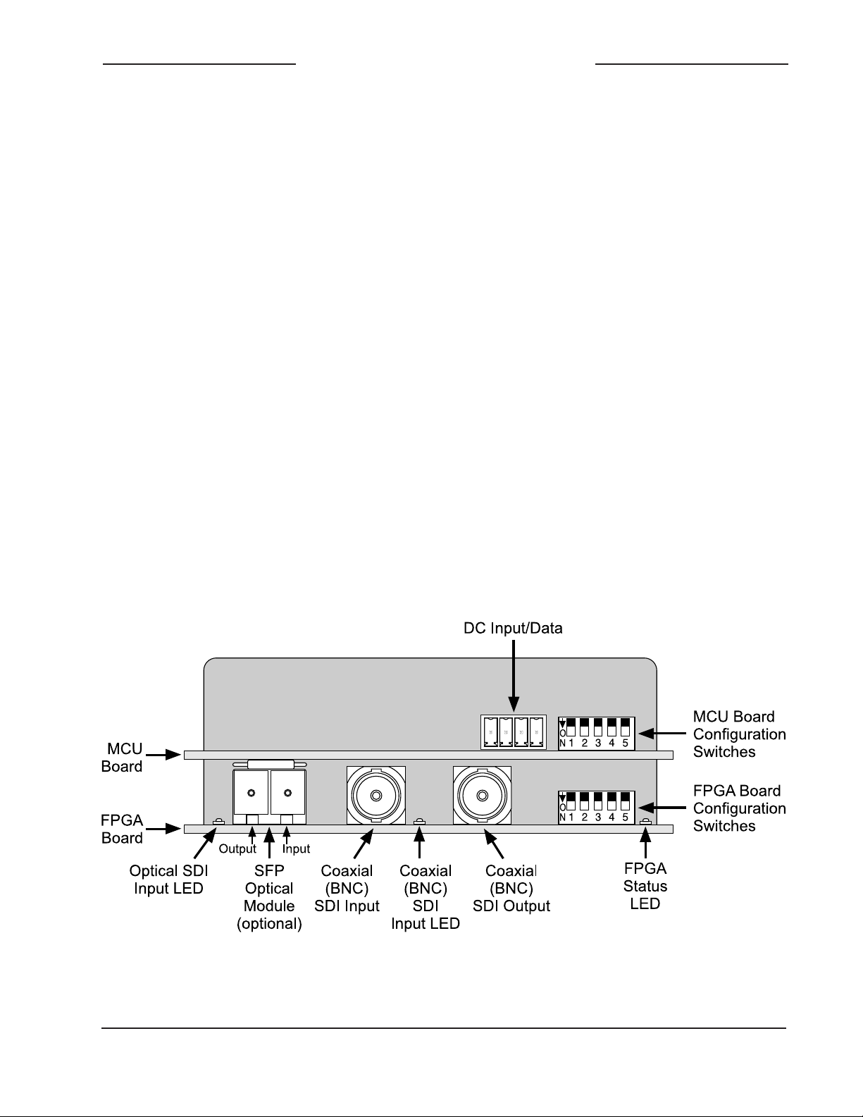
Figure 2. Detailed rear view of the Model 5150 Video Generator Module showing the MCU
and FPGA boards
Model 5150 User Guide Issue 1, June 2013
Studio Technologies, Inc. Page 9
Page 10

Video Generator
Model 5150
Module
Optical SDI Input
If supported by the specific Model 5150
module being installed, an HD- or 3G-SDI
signal transported on a single-mode optical fiber can be connected. For an input to
be present a video SFP transceiver or a
receive-only SFP module must have been
installed in the SFP “cage” in the back of
the unit. The optical receiver circuitry in an
SFP module is “broadband” and doesn’t
need to receive a specific wavelength of
single-mode optical signal for correct operation. As long as the optical signal has a
wavelength between 1250 and 1650 nanometers and meets the applicable SMPTE
standards it will be recognized correctly.
A single-mode optical fiber terminated
with an LC plug can be connected to the
receive port on the SFP module. This port
is on the right side when looking directly at
the back of the SFP module. Typically there
will be a graphic arrow icon pointing “in” on
the top of the module. Refer to Figure 2 for
details on the location of the SFP module.
Ensure that the LC plug fully “mates” with
the receive port and its tab is locked into
the slot of the SFP module.
A configuration switch must be appropriately set to enable the optical SDI input.
There is no automatic switching between
the optical and coaxial (BNC) SDI inputs.
Only one of the two SDI inputs can be
selected and active at a time. Refer to
the Configuration section of this guide
for details.
DC Input and Data Bus
A 4-position header is used to connect DC
power and a local RS-485 serial data bus
to the Model 5150. Two pins on the mating
connector are used to connect a source
of nominal 12 volts DC. The acceptable
range is 10 to 18 volts DC with a maximum
current of 400 milliamperes at 12 volts DC.
For remote control operation two pins on
the mating connector will implement the
data bus connection from a Studio Technologies’ Model 5190 Remote Access
Module.
The mating connector is compatible with
the AMP MTA-100 series of IDC recep
tacles. For 22 AWG wire the closed-endstyle receptacle is AMP 3-643813-4; the
feed-through-style receptacle, used for
busing connections, is AMP 3-644540-4.
The body color for both receptacles is red,
following the convention of the MTA-100
series for compatibility with 22 AWG wire.
Refer to Appendix B of this guide for addi
-
tional connector details.
1. – DC (Common)
2. + DC (10-18 volts)
+ Data (RS-485)
3.
4. – Data (RS-485)
Figure 3. DC Input and Data Bus Connections
Mounting
The Model 5150 is intended for mounting in an installation-specific enclosure or
rack panel. Refer to Appendix C at the end
of this guide for details on the required
mounting opening and screw locations.
Please contact the factory to discuss
mounting options.
Issue 1, June 2013 Model 5150 User Guide
Page 10 Studio Technologies, Inc.
Page 11

Video Generator Module
Model 5150
Configuration
Seven DIP switches are used to configure
the Model 5150’s operating functions. The
functions relate to SDI input selection, SDI
output image format/rate mode, RS-485
address, and moving image overlay. The
seven switches are located on the two circuit boards that comprise the Model 5150.
Two of the switches are on the FPGA
board which is the lower board. (There is
a total of five switches on the FPGA board
but only two are used to configure Model
5150 functions.) The other five switches
are on the MCU board which is the upper
board. The switches are a “piano key” type
with their up position being defined as off
and their down position defined as on.
SDI Input Select
The Model 5150 is capable of having its
SDI input in the form of a coaxial signal
(BNC connector) or an optical signal (SFP
module). All versions of the Model 5150
support the coaxial (BNC) input. The optical input is an option and may or may not
be present on the specific module you are
configuring.
Switch 1 on the FPGA board is used to
select which SDI input is active. When the
switch is in its off (up) position the coaxial
(BNC) input is selected. When the switch
is in its on (down) position the optical input
is selected. Of course an optical input will
only function if a factory-supplied SFP
module is physically present.
Figure 4. Rear view of Model 5150 showing
FPGA and MCU board configuration switches
Figure 5. SDI Input Select Settings
SDI Output Image Format/
Rate Mode
Switch 5 on the FPGA board is used to
configure how the format and rate of the
internal SDI generator is selected. (The in
ternal SDI generator creates the solid-gray
video image and plays back the custom
“720” and “1080” images.) When the switch
is in its off (up) position the format and rate
will automatically “follow” that of the connected SDI input. This allows the Model
5150 to automatically “learn” the specific
format and rate used by a broadcast facility
or live event.
-
Model 5150 User Guide Issue 1, June 2013
Studio Technologies, Inc. Page 11
Page 12
Video Generator
Model 5150
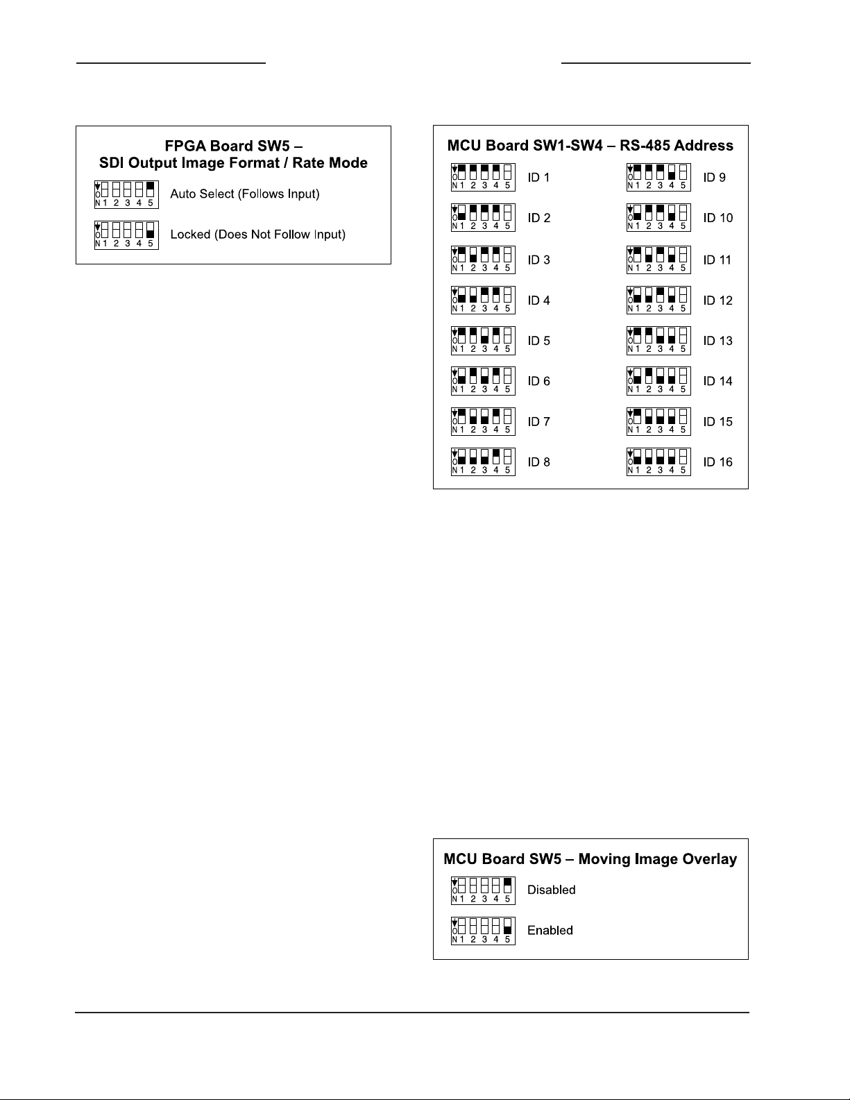
Figure 6. SDI Output Image Format/Rate Mode
Settings
The format and rate of the internal SDI generator can also be “locked” so that it will not
change. When switch 5 is in its down (on)
position the format and rate that’s currently
being used cannot be changed, no matter
what signal is connected to the SDI input.
Module
While the format and rate is “locked” when
switch 5 is down, it’s not difficult to change
the Model 5150 to a different “locked” format and rate. Begin by changing the mode
back to automatic by placing switch 5 on the
FPGA board to off (up). Then connect (or
leave connected) an SDI signal that has the
desired format and rate. After approximately
five seconds the new format and rate values
will be saved in nonvolatile memory. This will
serve as the new format/rate parameters.
Then return switch 5 to its on (down) position to “lock” the format/rate and prevent
further changes.
RS-485 Address
One configuration setting must be performed
for applications that implement remote control of Model 5150 functions. While up to 16
Model 5100-Series modules can “share” the
RS-485 data bus, each module must have
a unique address. Selecting the device’s
address involves setting four configuration
switches on the MCU board.
Figure 7. RS-485 Address Settings
Moving Image Overlay
A “moving” graphic image can be overlaid
onto the stored “720” and “1080” images
when either is being output by the Model
5150. The image is a red-colored box that
slowly moves around the screen. This
simple icon provides an indication to personnel located downstream of the Model
5150 that the SDI signal is active. This can
be important to ensure that a distinction
can be made between an active image and
an image that’s the result of the last valid
frame being held and displayed while an
SDI input is no longer present.
Figure 8. Moving Image Overlay Settings
Issue 1, June 2013 Model 5150 User Guide
Page 12 Studio Technologies, Inc.
Page 13

Video Generator Module
Model 5150
When switch 5 on the MCU board is in its
off (up) position the stored images (“720”
and “1080”) will be displayed without the
moving image being added. When the
switch is in its on (down) position the moving image will be added.
Note that the characteristics of the image
(color, size, and movement) can’t be modified. The image overlay function is created
in firmware (embedded software) with no
provision for users to alter it.
Operation
Power Up
Upon 12 volt DC power being applied to
the Model 5150 the four front-panel LEDs
will perform a “walk-through” test, with
each LED briefly lighting in sequence.
Then the LEDs will light in patterns that
represent the version numbers of the
firmware (embedded software) files that
are loaded into the module. Upon completion, the Power LED will continuously light.
For normal operation to commence, prior
to powering up the module ensure that
a USB flash drive is not plugged into the
USB port on the front panel.
Notes section of this guide for details. Fol
lowing the power-up sequence, the Power
LED will light and remain lit.
The USB Activity LED will not light during
normal Model 5150 operation. It will be lit
continuously or in a pattern when a USB
flash drive is plugged into the USB port
on the front panel and file transfer activity is taking place. Details on how the LED
functions when the USB port is active are
covered in the Technical Notes section of
this guide.
The SDI Input LED lights whenever a valid
SDI signal is connected to the coaxial
(BNC) or optical SDI input. (A configuration
choice selects whether the coaxial (BNC)
SDI input or optical SDI input is active.)
The Data LED will light whenever data activity is taking place over the local RS-485
signal bus that is used to link the Model
5150 to a Studio Technologies’ Model 5190
Remote Access Module. The LED will flash
on and off each time data associated with
this specific Model 5150 is present. Not all
applications will include a connection to
the data bus so it’s certainly possible that
the Data LED may never flash except during module power up.
-
LED Indicators
FPGA Board LEDs
A brief discussion of the Model 5150’s status LEDs will be covered in this section.
Front-Panel LEDs
As previously discussed, upon power up
the four front-panel LEDs will light in a
short sequence as an initialization test.
Afterwards they are used to display the
version number of the installed MCU and
FPGA firmware. Refer to the Technical
Model 5150 User Guide Issue 1, June 2013
Studio Technologies, Inc. Page 13
Three LEDs are located on the back edge
of the FPGA printed circuit board and
serve as factory- and field-diagnostic aids.
Upon Model 5150 power up each LED
will light for several brief durations with
no specific meaning associated with them.
Then the FPGA Status LED, located
adjacent to the configuration switches,
will light and remain lit. This indicates that
the FPGA and MCU boards are correctly
communicating.
Page 14

Video Generator
Model 5150
Module
The LED located adjacent to the coaxial
SDI input’s BNC connector will light whenever that input has been configured to be
active and a valid SDI signal is connected.
It will not light if a valid SDI signal is con
nected but the SDI input configuration
switch is not set to activate the coaxial
(BNC) input.
The LED located adjacent to the “cage”
that holds the SFP module will light if the
optical SDI input has been selected and a
valid SDI optical signal is connected. It will
not light if a valid optical signal is connected but the SDI input configuration switch
is not set to activate the optical input.
A fourth LED is located near the front of
the FPGA board. Called the FPGA Done
LED, it lights whenever the logic device
(FPGA) has loaded its firmware and is
operating normally. This LED is provided
only for factory troubleshooting use.
Initial SDI Output
After the power-up sequence has been
completed the module’s SDI output will become active. (This will be both the coaxial
(BNC) output and, if present, the optical
SDI output.) If a valid signal is connected
to the SDI input it will be routed to the SDI
output. If a signal is not connected to the
SDI input the internal SDI generator will
supply a signal to the SDI output. In the
latter case, after the Model 5150 power-up
sequence has taken place (about seven
seconds) a solid-gray image will be output
for approximately seven seconds. Then
either the custom “720” or “1080” image
will be displayed.
SDI Input and SDI Output
Depending on the exact Model 5150 version that has been installed and how it was
configured an SDI signal can be connected
to the coaxial (BNC) input or the optical
input. When a signal that’s compatible with
the Model 5150 has been connected the
front-panel SDI Input LED will light. This
indicates that the signal is being routed
to the SDI output and the internal SDI
generator is not active. SDI signals that
comply with most HD (1.485 Gb/s nominal)
and 3G (2.97 Gb/s nominal) standards
are compatible. Refer to the Specifications
section of this guide for a list of the sup
-
ported standards.
The Model 5150 always provides an active
SDI signal on the coaxial (BNC) output.
Some Model 5150 versions also provide
an optical output. This is accomplished at
the factory by installing one of a variety of
available SFP optical modules in the backpanel SFP “cage.” If an optical output is
present it will always be active and provide
an identical copy to the signal present on
the coaxial (BNC) output.
If a valid SDI signal is not connected to the
selected SDI input the custom image will
be present on the coaxial (BNC) output
and, if present, optical output. Depending
on the stored format and rate values, the
output will be either a 1280 x 720 pixel
(“720”) or 1920 x 1080 pixel (“1080”) fixed
image.
Stored Images
When a valid signal is not connected to
the selected SDI input, the module generates one of two fixed images. The two
images, one “720” and one “1080,” are
stored in nonvolatile memory within the
Model 5150. From the factory two images
are pre-loaded. The two are quite different from one another with each having a
unique photo background and overlaid text.
Issue 1, June 2013 Model 5150 User Guide
Page 14 Studio Technologies, Inc.
Page 15

Video Generator Module
Model 5150
The overlaid text provides support details
on how alternate custom images can be
created.
It’s expected that these pre-loaded images
will be replaced with application-specific
images. They can be easily created and
what they consist of is limited only by one’s
imagination. Refer to the Technical Notes
section of this guide for details.
Transitions between External
and Internal SDI Signals
Whenever a valid SDI signal is connected
to the selected Model 5150 input it will immediately be routed to the coaxial (BNC)
and, if present, optical SDI outputs. The
situation is a little different when a valid
signal that’s been connected to the SDI
input is subsequently removed. When
the Model 5150 detects that an SDI input
signal is no longer present the SDI output
switches to an image with a solid-gray
color. This color remains active for approximately seven seconds as a benign warning
to users that the normal SDI source is no
longer present. During this time period it’s
expected that any on-air use of the Model
5150’s output can be terminated without
alerting viewers that anything is amiss.
This gray image can also be helpful as a
marker when editing recorded video. After
the seven-second interval has elapsed the
internal generator will output either the
“720” or “1080” stored image.
It’s important to note that the Model 5150
does not perform a smooth transition when
switching between an external SDI source
and the internal SDI generator. The same
holds true when the internal color or image
generator is active and then a valid source
is connected to the SDI input. The SDI
output does not stay “locked” during the
transition as the circuitry in the Model 5150
was not designed to that level of sophistication. This shouldn’t cause an operational
issue as the Model 5150 was not designed
to be “on air” during those transitions; the
changeover process is not seamless by
design. One can assume that up to two
seconds of interruption will occur during
transitions but typically it will be considerably shorter.
Output Format and Rate
When a valid signal is connected to the
SDI input it will be routed to the SDI output at the identical format and rate of the
source. When the SDI input is no longer
present the internally-generated signal will
become active and be routed to the SDI
output. The format and rate of the internally-generated SDI signal will depend
on parameters that are stored within the
Model 5150. Whether these parameters
can change depends on the configuration
of the module’s SDI output image format/
rate mode. Typically, the mode will be set
for Auto Select which allows the Model
5150 to revise its parameters by following
the format and rate of the connected SDI
signal. This ensures that the Model 5150
can generate an SDI signal that matches
the requirements of a facility or event. For
the module to “learn” a new format and
rate simply requires the momentary connection of an SDI signal that has the desired format and rate. As long as the signal
is present on the SDI input for a minimum
of five seconds the Model 5150 will store
the “new” format and rate parameters in
nonvolatile memory. The module will then
use those parameters whenever the internal generator is active. The only caveat
for the module to “learn” a new format/rate
Model 5150 User Guide Issue 1, June 2013
Studio Technologies, Inc. Page 15
Page 16

Video Generator
Model 5150
combination is that it must be a compatible
combination. Refer to the Specifications
section of this guide for a complete list.
There are some applications that will benefit from the internally-generated SDI output
signal always having a specific format and
rate. In this case the SDI output image
format/rate mode can be set for Locked.
No matter what the format and rate of a
connected SDI signal, the stored parameters will not change. Changing the stored
parameters would require the format/rate
mode to be changed to Auto Select, an
SDI signal with the desired format and
rate be connected for a minimum of five
seconds, and then the format/rate mode
changed back to Locked.
Moving Image Overlay
The Model 5150 has the ability to overlay
a moving image on top of the stored “720”
and “1080” images. A configuration setting
selects whether the moving image overlay
will be active. The moving image, a box
that’s red in color, slowly moves around
and on top of whatever stored image is
present on the SDI output. The color, size,
and rate of motion of the “box” are fixed in
the FPGA’s firmware (embedded software)
and can’t be altered.
The moving image is provided specifically
so that users who are “downstream” from
the Model 5150’s SDI output are assured
that the “720” or “1080” image they are
viewing is active. And, just to clarify, if
a signal is present on the Model 5150’s
selected SDI input it will be passed on to
the coaxial (BNC) and, if present, optical
SDI outputs. The moving image will never
overlay an input signal—it can only overlay
on top of the stored image.
Module
Technical Notes
Bitmap Image File
Requirements
The Model 5150 allows two bitmap (.bmp)
images to be stored and output when an
SDI input signal is not present. One image has a pixel size of 1280 x 720 while
the other has a pixel size of 1920 x 1080.
To be stored with the Model 5150 the
files must be FAT32-compatible and have
names of img720.bmp and img1080.
bmp, respectively.
The reason two files are required is simple:
the Model 5150 does not have the ability to
digitally “scale” a 1920 x 1080 image down
to 1280 x 720. But it does have the ability
to store two unique files. Most users will
create a single image using a personalcomputer graphics program and then save
it in the two required formats. So when the
Model 5150 generates either of the two
images (“720” or “1080”), a user will see
what appears to be an identical image.
But there is no reason why the two images
(“720” and “1080”) have to be based on the
same original graphics. Studio Technolo
gies chose to create two different “720”
and “1080” bitmap files that are pre-loaded
in the Model 5150 at the time of manufacture. They feature two unique background
images with text highlighting the main
requirements for updating them.
While the two bitmap files (img720.bmp
and img1080.bmp) are “standard” in the
sense that they are FAT32-compatible and
have the extension .bmp, they must adhere
to one important requirement that not all
personal-computer graphics programs support. Their DIB (bitmap information header)
must be a BITMAPINFOHEADER type.
-
Issue 1, June 2013 Model 5150 User Guide
Page 16 Studio Technologies, Inc.
Page 17

Video Generator Module
Model 5150
The Microsoft Paint and Adobe Photoshop
applications will create .bmp files that meet
this requirement. But some other programs
may produce non-compatible files. For example, the open-source GIMP graphics program is very good but appears to save .bmp
files only as a BITMAPV4HEADER type.
These are not compatible with the Model
5150. The possibility that various .bmp files
will have different header types doesn’t
seem to be an issue for displaying them
successfully with most personal-computer
programs. This is most likely due to the PC’s
large code space allowing essentially all the
possible header types to be supported. But
the Model 5150, due to its target application, has limitations in the file support area.
(For additional background information,
please refer to the Wikipedia online entry
that discusses the structure of .bmp files.)
A compatible 1280 x 720 (“720”) .bmp file
created using Microsoft Paint or Adobe
Photoshop will have a size of approximately
2.63 MB; a 1920 x 1080 (“1080”) .bmp file
will have a size of approximately 5.63 MB.
The actual size of the files when created in
Microsoft Paint should be 2,764,854 bytes
and 6,220,854 bytes, respectively. When
created in Adobe Photoshop, the file sizes
should be 2,764,856 bytes and 6,220,856
bytes, respectively. (Why are they each two
bytes in size different? Who knows! But both
use the appropriate BITMAPINFOHEADER
DIB type.)
Bitmap Image Update
Procedure
It’s expected that the Model 5150’s bitmap
(.bmp) files associated with the custom
“720” and “1080” images will always be
updated to best serve specific applications.
This will typically take place soon after a
Model 5150 has been installed. (While the
pre-loaded images are nice, they aren’t
really appropriate for actual active applica
tions.) There’s no problem changing the
files whenever the application warrants
alternate images. The module has the
ability to automatically load revised files by
way of its USB interface. The Model 5150
implements a USB host function that
directly supports connection of a USB
flash drive.
Updating the Model 5150’s “720” and
“1080” images is quite simple but requires
some care. The process begins by preparing a USB flash drive. The flash drive
doesn’t have to be empty (blank) but must
be in the personal-computer-standard
FAT32 format. Save the new image (.bmp)
files in the root directory. Their names
must be img720.bmp and img1080.bmp.
Typically both .bmp files will be updated at
the same time. But there’s no requirement
to do so. Individual files can be updated
whenever desired. Simply copy the desired
file or files to the root directly on the USB
flash drive. Be certain that there are no
Model 5150 firmware files (m5150.s19 and
m5150.bit) present on the USB flash drive
during this process.
As previously reviewed in this guide, the
1280 x 720 image must have a file name of
img720.bmp; the 1920 x 1080 image must
have a file name of img1080.bmp. Also
ensure that both have the DIB header type
BITMAPINFOHEADER so that they can be
recognized correctly by the Model 5150.
To install the new image files:
1. Power down the Model 5150 module.
2. Insert the prepared USB flash drive into
the module’s USB port.
Model 5150 User Guide Issue 1, June 2013
Studio Technologies, Inc. Page 17
Page 18

Video Generator
Model 5150
Module
3. Apply power to the module.
4. The module will go through its power-up
LED sequence and normal operation will
begin. At about the same time that normal operation starts the new .bmp files
will begin to load, one after the other.
The USB Activity LED on the module’s
front panel will flash while the loading
process is taking place. Loading both
.bmp files will take approximately 6.5
minutes. (Loading only the img720.bmp
file takes approximately 2 minutes; loading only the img1080.bmp file takes
approximately 4.5 minutes.) Once the
loading process has been completed the
USB Activity LED will change from flashing to being continuously lit.
Note: If the module is currently output-
ting one of the stored images and a new
image of the same type (“720” or “1080”)
has just completed loading, the output
will automatically change to the new image. (It’s possible that a few seconds of
a solid color could be output during the
transition from the old image to the new
image.)
5. Power down the module.
6. Remove the USB flash drive from the
module’s USB port.
7. Power up the Model 5150 module. It will
go through its normal power-up LED
sequence and begin operation. It will use
the updated images whenever the internal SDI generator is active.
It’s possible that during the update process
any LEDs located on the USB flash drive
may light steadily or flash with varying patterns. These actions are not significant to
the Model 5150’s update procedure. (The
status LEDs on various USB flash drives
seem to behave in different ways so there
are no universal patterns that can be
identified.)
Firmware Update Procedure
It’s possible that updated versions of the
firmware (embedded software) that runs
the Model 5150 will be released to add
features or correct issues. The module
has the ability to automatically load revised files by way of its USB interface. The
Model 5150 implements a USB host function that directly supports connection of a
USB flash drive. The Model 5150 uses two
firmware files to perform its functions. One
file is used by the microcontroller integrated circuit (MCU) and has a file name
of m5150.s19. The microcontroller is the
overall “boss” of the Model 5150, doing
pretty much everything but the SDI-related
tasks. The other firmware file is used by
the logic chip (FPGA) and has a name
of m5150.bit. This firmware, running in
the FPGA, creates the video images and
processes the SDI signals. The factory will
provide updates of these firmware files if
it’s warranted for your specific Model 5150
module.
To update the Model 5150’s firmware is
quite simple but requires careful execution.
The process begins by preparing a USB
flash drive. The flash drive doesn’t have
to be empty (blank) but must be in the
personal-computer-standard FAT32 format.
Save the new firmware files in the root
directory. Their names must be m5150.s19
and m5150.bit. Be certain that any custom
image files (img720.bmp and img1080.
bmp) are not present on the USB flash
drive during this process.
Issue 1, June 2013 Model 5150 User Guide
Page 18 Studio Technologies, Inc.
Page 19

Video Generator Module
Model 5150
Studio Technologies will supply the MCU
and FPGA files inside individual .zip archive files. While the firmware file inside
of each zip file will adhere to the naming
convention required by the Model 5150, the
name of the zip file itself will include the
version number. For example, a file named
m5150v1r2MCU.zip would indicate that
version 1.2 of the MCU firmware (m5150.
s19) is contained within this zip file; a file
named m5150v1r1FPGA.zip would indicate
that version 1.1 of the FPGA (m5150.bit)
is contained within this zip file. The version
numbers of the files that are copied to the
USB flash drive should be noted for later
reference. Once the new files are loaded
into a Model 5150 the module’s front-panel
LEDs should be used to confirm that the
correct firmware versions have been successfully installed.
Note: The firmware update procedure itself
will not erase or overwrite bitmap image files
that are already saved in the Model 5150.
However, this requires that the custom im
age files (img720.bmp and img1080.bmp)
are not present on the USB flash drive.
To install the firmware files:
1. Power down the Model 5150 module you
intend to upgrade.
2. Ensure nothing is inserted into the USB
port on the module. Power up the module and “read” the version numbers of
the currently-installed MCU (m5150.s19)
and FPGA (m5150.bit) files. Write these
numbers down for reference. The next
section of this guide details how to “read”
the installed firmware version levels.
3. Power down the Model 5150 module.
4. Insert the prepared USB flash drive into
the module’s USB port.
5. Apply power to the Model 5150 module.
6. The module will run a “boot loader”
program that will immediately load the
new MCU (m5150.s19) file. This takes
approximately six seconds. Once the
file is loaded the module will perform
a normal power-up sequence with the
microcontroller using its newly-loaded
MCU firmware.
7. After the power-up sequence has been
completed the module will begin operation. It will process video as well as
checking for an FPGA (m5150.bit) file on
the USB flash drive. If it doesn’t find this
file normal operation will continue. If it
locates this file it will begin to load it from
the USB flash drive. In that case, some
Model 5150 functions will halt, including reading changes to the configuration
switches. As an indication that the file
transfer is under way, the USB Activity
LED will flash on and off.
8. The process of loading the FPGA
(m5150.bit) file will take approximately
90 seconds to complete. When the file
loading process is complete you will
see the module’s front-panel USB Activity LED change from flashing to being
continuously lit. At that time the Model
5150’s logic chip (FPGA) will reboot and
run under the newly-loaded firmware.
9. Power down the module.
10. Remove the USB flash drive from the
module’s USB port.
11. Power up the Model 5150 module and
it will begin operation using the updated
MCU and FPGA firmware. The version
numbers of the installed MCU and FPGA
firmware should be “read” by way of the
front-panel LEDs. Compare and confirm
that these numbers match those from the
zip file names that were provided by the
factory.
Model 5150 User Guide Issue 1, June 2013
Studio Technologies, Inc. Page 19
Page 20

Video Generator
Model 5150
Module
Note: It’s possible that during the update
process any LEDs located on the USB
flash drive may light steadily or flash with
varying patterns. These actions are not
significant to the Model 5150’s firmware
update process. (The status LEDs on various USB flash drives seem to behave in
different ways so there are no universal
patterns that can be identified.)
Identifying the Installed
Firmware Versions
The four status LEDs on the front panel
of the Model 5150 are used during the
power-up sequence to identify the version
number of the installed MCU and FPGA
firmware (embedded software). While the
display method is a bit unique, once a
user gets accustomed to what’s actually
happening during power up it should be
fairly straightforward to “read” the version
numbers.
To identify the installed firmware versions:
The USB Activity LED lights to represent the number 1
The SDI Input LED lights to represent the number 2
The Power LED lights to represent the number 3
The Data LED lights to represent the number 4
Figure 9. Detail of front panel showing how
the LEDs display the MCU and FPGA firmware
version numbers.
3. After another slight pause one of the
LEDs will light briefly. This will indicate
the major number of the FPGA’s firmware version. The LED will stop lighting
then another one of the four LED will light
briefly to indicate the minor number of
the FPGA’s firmware version. The range
of each is 1-4. A period (.) is inserted
between the major and minor numbers.
1. Power up the Model 5150. The four
LEDs will perform a “walk-through”
test, with each LED briefly lighting
in a sequence.
2. After a slight pause one of the four
LEDs will light briefly. This will indicate
the major number of the MCU’s firmware version. The LED will stop lighting then another one of the four LED
will light briefly to indicate the minor
number of the MCU’s firmware version.
The range of each is 1-4. A period (.) is
inserted between the major and minor
numbers.
As an example, if the USB Activity LED
lights first followed by the SDI Input
LED lighting this would indicate version
1.2 of the MCU firmware.
Issue 1, June 2013 Model 5150 User Guide
Page 20 Studio Technologies, Inc.
As an example, if the SDI Input LED
lights twice this would indicate version
2.2 of the FPGA firmware.
4. After a final short pause the four LEDs
will begin performing in their normal operating manner. The Power LED will light
and remain lit. The USB Activity LED will
only be active when a USB flash drive is
inserted and file transfer activity is taking place. The SDI Input LED will light
whenever a valid SDI signal is connected
to either the coaxial (BNC) input or the
optical input, depending on the module’s
capability and configuration setting. The
Data LED will light whenever local data
is received via the RS-485 data bus
from a Studio Technologies’ Model 5190
Remote Access Module.
Page 21

Video Generator Module
Model 5150
SFP Module Flexibility
The Model 5150 was designed to allow an
MSA-compliant SFP optical module to be
installed at the factory. Optical modules are
available with a range of input and output
capabilities to meet the needs of various
applications. For maximum flexibility the
SFP mating connector and associated
“cage” on the Model 5150’s FPGA circuit
board were implemented to meet the
electrical and mechanical requirements
of the MSA SFP standard. The MSA SFP
standard was originally developed for use
with optical data (Ethernet) modules. It
has also become popular for use with SFP
modules that support SMPTE-compliant
SDI signals.
It’s interesting to note that several companies offer non-optical SFP modules that
support the MSA SFP standard as well.
For example, Embrionix of Canada offers
a wide range of specialized SFP modules.
These include coaxial SDI input and output
modules that use DIN 1.0/2.3 and HD-BNC
connectors. In addition, they offer SFP
modules that provide an HDMI® output.
Several of these modules have been installed and tested in Model 5150 modules
at the factory and acceptable performance
was confirmed. It’s possible that special
applications could benefit from the features
provided by installing these non-optical
SFP modules in a Model 5150. For further
dialog about this topic please contact
Studio Technologies technical support.
USB Port Capabilities
The USB port, accessible on the Model
5150’s front panel, is provided for use in
only a few specific tasks. While it implements a high-speed USB host interface,
it is not intended for general-purpose use
and does not support connection with
mass-storage devices, personal computers, printers, etc. It is intended only for use
with USB flash drives. These devices can
contain image and firmware files that are
intended for loading into the Model 5150.
Details on these file-transfer functions can
be found in other sections of this guide.
Model 5150 User Guide Issue 1, June 2013
Studio Technologies, Inc. Page 21
Page 22

Video Generator
Model 5150
Specifications
SDI Compatibility, Supported Formats and Rates:
HD-SDI per SMPTE ST 292:2011:
720p: 50, 59.94, 60
1080i: 50, 59.94, 60
1080p: 23.98, 24, 25, 29.97, 30
1080psf: 23.98, 24, 25
3G-SDI Level A per SMPTE ST 424:2006 and
ST 425:2011:
1080p: 50, 59.94, 60
SD-SDI per SMPTE® ST 259:2008:
Not supported
Module
Connectors:
Coaxial SDI Input and Output: BNC, 3G-SDI
optimized, gold plating on center pin, per IEC
61169-8 Annex A
Optical Module: MSA-compliant SFP
DC Input/Data: 1, 4-position male header. Refer
to Appendix B for mating connector details.
Power Requirement: 12 volts DC nominal,
400 mA max; acceptable range 10-18 volts DC,
480 mA max at 10 volts
Dimensions (Overall):
3.75 inches wide (9.5 cm)
1.69 inches high (4.3 cm)
2.30 inches deep (5.8 cm)
Coaxial (BNC) SDI Input and Output:
Type: unbalanced
Impedance: 75 ohms
Level: 800 mV p-p, nominal
Optical Input (optional):
Compliance: SMPTE ST 297:2006 (as applicable)
Fiber Type: single mode
Wavelengths Supported: 1250 to 1650 nm
Receive Sensitivity: –17 dBm, nominal @
2.97 Gb/s
Maximum Input Power: –3 dBm, nominal
Optical Output (optional):
Compliance: SMPTE ST 297:2006 (as applicable)
Fiber Type:
Wavelength: 1310 nm (FP laser) or CWDM (DFB
laser), as per order
Launch Power:
Typical Fiber Interconnect Length:
minimum
single mode
–3 dBm, nominal
10 km
Mounting: requires custom implementation;
no mounting method provided. Refer to Appendix C
for details.
Weight: 0.2 pounds (91 g)
Specifications and information contained in this
User Guide subject to change without notice.
Remote Control Data Interface: RS-485 115.2 Kb/s,
8-1-N; compatible with Studio Technologies’ Model
5190 Remote Access Module
Issue 1, June 2013 Model 5150 User Guide
Page 22 Studio Technologies, Inc.
Page 23

Video Generator Module
Model 5150
Appendix A–Model 5150 Versions
The following list describes the available Model 5150 versions along with their respective
order codes. List is current as of the publication date of this guide.
Version Order Code Figure
Model 5150 Video Generator Module M5150 A
Model 5150 Video Generator Module with Optical Output (1310 nm) M5150-01 B
Model 5150 Video Generator Module with Optical Input/Output (1310 nm) M5150-02 C
Model 5150 Video Generator Module with CWDM Optical Output M5150-03X* B
Model 5150 Video Generator/ Module with Optical Input/CWDM Output M5150-04X* C
* For order codes -03X and -04X, X = the standard CWDM wavelength letter code, e.g., L=1490 nm.
Figure A (No SFP)
Figure B (Optical-Output-Only SFP)
Figure C (Transceiver SFP)
Model 5150 User Guide Issue 1, June 2013
Studio Technologies, Inc. Page 23
Page 24

Video Generator
Model 5150
Module
Appendix B–DC Input/Data Interconnection Details
The required mating receptacle is from the TE Connectivity (formerly AMP) MTA-100 series
of IDC (insulation displacement) connectors. This series was selected because of its lowcost and wide range of offerings. Separate connectors are offered for compatibility with 22,
24, 26, and 28 AWG (American Wire Gauge) insulated wire. The connector color indicates
its AWG-compatibility. Unfortunately, with flexibility can come some confusion. The MTA-100
offers a number of different connectors that will work with the DC input/data header. Before
obtaining receptacles it’s important to determine two things: wire gauge and wiring arrangement. For this application 22 AWG is recommended.
DC Input/Data
• For 22 AWG wire this receptacle (red in color) is recommended:
TE Connectivity (AMP) 3-643813-4, closed-end type
Digi-Key part number A31108-ND
Mouser part number 571-3-643813-4
TE Connectivity (AMP) 3-644540-4, feed-through type
Digi-Key part number A31122-ND
Mouser part number 571-3-644540-4
Tools for Connecting Wires to the Mating Receptacles
For applications where just a few Model 5100-Series modules are going to be installed a
manual IDC termination tool is recommended. While requiring a steady hand to achieve
reliable wire connections to the mating receptacles, the price, at less than US$40, is fairly
reasonable:
• “T Handle” termination hand tool:
TE Connectivity (AMP) 59803-1
Digi-Key part number A9982-ND
Mouser part number 571-598031
Issue 1, June 2013 Model 5150 User Guide
Page 24 Studio Technologies, Inc.
Page 25

Video Generator Module
Model 5150
Appendix B–Interconnection Details, continued
Tools for Connecting Wires to the Mating Receptacles, continued
For applications where a larger number of Model 5100-Series modules are going to be
installed it’s worth considering a semi-automatic termination tool. The recommended tool
consists of a handle assembly and crimp die for MTA-100 receptacles. The total price for
both, approximately US$300 as of this writing, is steep but the performance that this tool
assembly provides is excellent. We feel that the time savings and reliability of the connections may warrant the price when many terminations are going to be made:
• Handle Tool, Pistol Grip:
TE Connectivity (AMP) 58074-1
Digi-Key part number A2031-ND
Mouser part number 571-580741
• Crimp Head Die Assembly for MTA-100 Receptacles:
TE Connectivity (AMP) 58246-1
Digi-Key part number A1998-ND
Mouser part number 571-58246-1
Header on the Model 5150 Printed Circuit Board
The actual part number of the header connector that is soldered into the Model 5150’s
printed circuit board is provided in this section. But do not order this part number with
the intent of interconnecting signals with the Model 5150! We are providing this detail only
so that interested technical personnel can have the full background on the Model 5150’s
interconnect system. The appropriate mating receptacle is detailed in a previous section
of this Appendix.
• DC Input/Data:
TE Connectivity (AMP) 2-644486-4 (DO NOT ORDER THIS NUMBER!)
Model 5150 User Guide Issue 1, June 2013
Studio Technologies, Inc. Page 25
Page 26

Video Generator
Model 5150
Module
Appendix C–Model 5150 Front Panel and Printed Circuit Board (PCB) Dimensions
Issue 1, June 2013 Model 5150 User Guide
Page 26 Studio Technologies, Inc.
Page 27

 Loading...