

Page 1

Model 5120
Line/IFB Output Module
User Guide
Issue 3, November 2011
This User Guide is applicable for serial numbers
M5120-00151 and later
Copyright © 2011 by Studio Technologies, Inc., all rights reserved
www.studio-tech.com
50176-1111, Issue 3
Page 2

This page intentionally left blank.
Page 3

Model 5120
Line/IFB Output Module
Table of Contents
Introduction ................................................................... 5
Installation .................................................................... 7
Configuration ................................................................ 8
Operation ...................................................................... 9
Technical Notes ............................................................ 11
Specifications ............................................................... 16
Appendix A—Model 5120 Front Panel and
Printed Circuit Board (PCB) Dimensions ...................... 17
Model 5120 User Guide Issue 3, November 2011
Studio Technologies, Inc. Page 3
Page 4

Model 5120
Line/IFB Output Module
This page intentionally left blank.
Issue 3, November 2011 Model 5120 User Guide
Page 4 Studio Technologies, Inc.
Page 5
Model 5120
Line/IFB Output Module
Introduction
The Model 5120 Line/IFB Output Module is
a compact, self-contained 2-channel module intended for use in custom broadcast,
live-performance, and other specialized
audio applications. The module provides
broadcast and production talent cueing
interfaces, specifically two line-level (“dry”)
and one IFB (“wet”) outputs, in an easy-touse yet technically sophisticated package.
(Note that IFB is an acronym for Interrupted Fold Back, an arcane broadcast technical term meaning the cue signals sent
to on-air talent or other technical support
personnel.) The module’s basic functions
include selectable analog and digital audio
inputs, input level and status LED indicators, two analog line-level outputs, and a
2-channel DC-biased (“wet”) broadcaststandard IFB output. Module operation
requires only a source of analog or digital
audio, along with an externally-provided
source of 12 volts DC.
Applications for the Model 5120 include
sports broadcasting booth packages,
remote news gathering “fly-packs,” stadium
audio/video interface (I/O) locations, and
other broadcast-infrastructure projects.
The number of Model 5120 modules used
in a project can vary widely—from one to
dozens. In each case the Model 5120’s
performance will be completely “pro” with
audio quality, reliability, and installation
flexibility matching that of larger-scale
audio consoles, matrix intercom systems,
and stand-alone IFB systems. Typical
applications will find the Model 5120’s
analog and digital inputs being interfaced with outputs provided by fiber-optic
transport modules, audio/video routers,
broadcast/production consoles, and matrix
intercom systems.
The Model 5120’s line-level outputs would
typically be connected to battery-powered
listen-only headphone amplifiers, amplified
speakers, or inputs on broadcast media
storage systems. In remote-broadcast
applications these two outputs may be
referred to as “dry” (no DC voltage present)
IFB signals. The Model 5120’s IFB output
is directly compatible with listen-only por
table IFB amplifiers, such as the Models
32A, 33A, or 34A from Studio Technolo
gies, Inc. The 2-channel IFB output provides signal common on one pin, +28 volt
DC power with superimposed analog audio
on a second pin, and analog audio only on
a third pin. This complies with a long-popular broadcast-standard implementation.
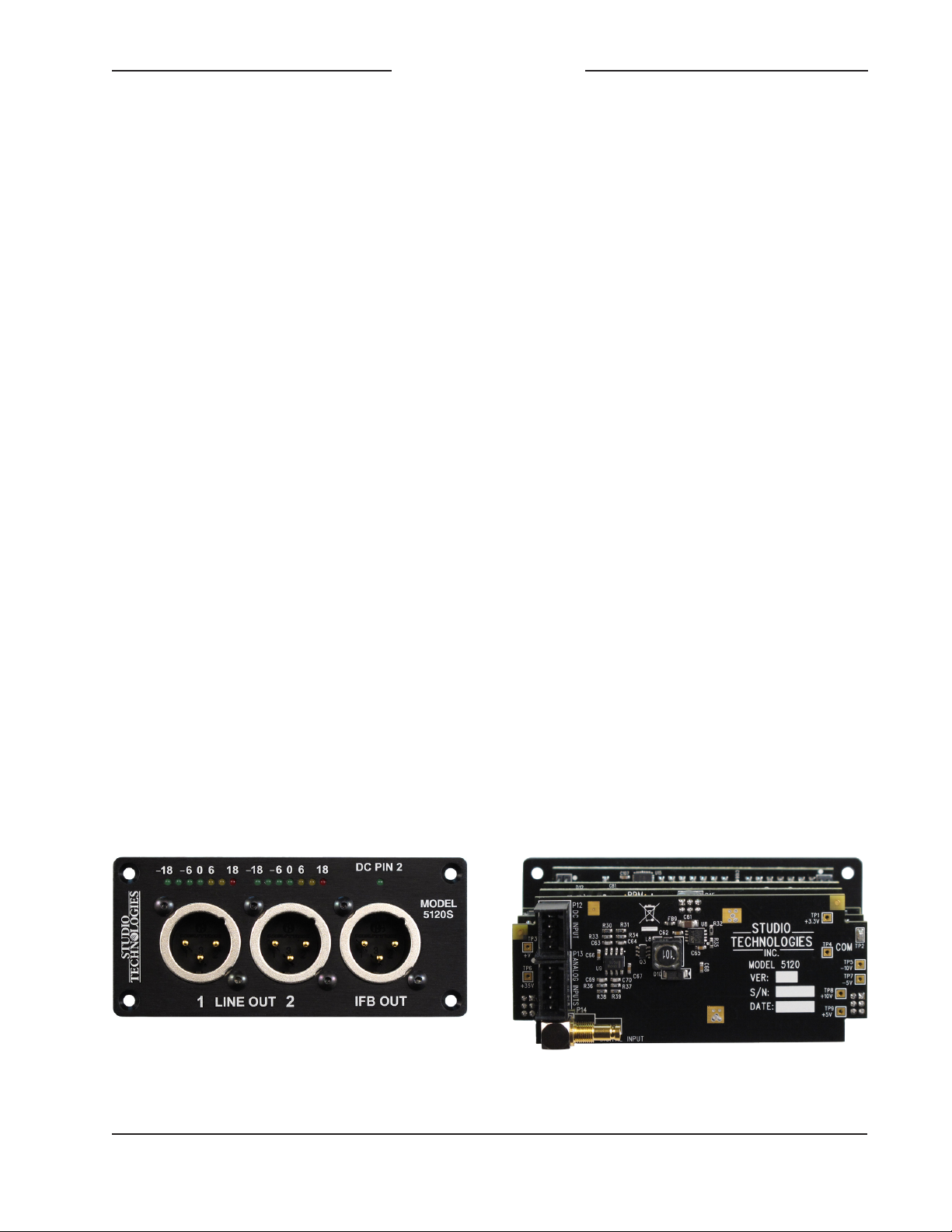
Figure 1. Model 5120S Line/IFB Output Module front and back views
Model 5120 User Guide Issue 3, November 2011
Studio Technologies, Inc. Page 5
Page 6

Model 5120
Line/IFB Output Module
Model 5120 Line/IFB Output Modules do
not include a mounting enclosure or chassis. They are intended for mounting in
custom 19-inch rack panels, equipment
boxes, broadcast furniture, or other spe
cialized settings. It is expected that integration firms will create applications that use
Model 5120 modules as part of complete
broadcast, production, corporate, and
government solutions.
Separate audio inputs are provided for
interfacing with analog and digital audio
sources. The two analog inputs are balanced (differential) and compatible with
line-level signals. An unbalanced AES3id
digital audio input allows the connection
of two digital audio channels. A configuration DIP-type switch allows selection of the
desired input signal. Two 7-segment LED
meters provide the user with an indication
of the inputs levels.
The Model 5120’s audio performance is
very good. Low-noise, wide dynamic-range
circuitry ensures that the input audio quality is preserved. The audio from the digital
audio input is routed to a high-performance
digital-to-analog conversion (DAC) section
that supports sample rates of up to 48 kHz
with a bit depth of up to 24. The outputs
of the analog inputs or DAC circuitry are
routed to two line-level analog audio out
put sections. These provide the line-level,
balanced (differential), ESD-protected,
capacitor-coupled output signals.
The two analog signals from the selected
input channels are also routed to the IFB
circuitry. One channel is used to modulate
the DC power source circuitry. The second
channel is routed to a single-ended (unbalanced) line-driver circuit. The IFB power
source circuitry provides a low-noise,
current-limited source with a nominal
28 volt DC output. This is essentially identical to that created by “big time” broadcast
IFB systems. Logic circuitry contained
within the Model 5120 monitors the DC
output voltage. Should a low-voltage/overcurrent condition be detected the DC
output enters a protection mode. Once the
fault condition is removed normal operation will again resume. An LED, located on
the Model 5120’s front panel, provides an
indication of the IFB output’s status. Note
that for additional flexibility, the source
impedance of both IFB output channels is
200 ohms, allowing intercom “beltpacks” to
also serve as listen-only devices.
All audio inputs and outputs were carefully
designed for use in permanent as well as
field applications. Filtering on the inputs
minimizes the chance that radio frequency
(RF) energy will interfere with audio input
sources. Other components were included
to address ESD (“static”) and DC overvoltage conditions The DC power input is
protected from accidental polarity reversal.
The Model 5120 requires an external
source of nominal 12 volts DC for operation. The acceptable input voltage range
is 10 to 18 allowing a variety of power
sources to be utilized. Internal power sup
ply circuitry within the Model 5120 creates
the voltages required for the analog audio,
digital audio, and IFB circuitry.
Standard connectors are used throughout the Model 5120. Line-level and IFB
output connections are made using 3-pin
male XLR-type connectors. The two analog audio inputs use a 5-position, 0.1-inch
“header” connector. A DIN 1.0/2.3 coaxial
connector is used to interface with the digital audio input. The DC power input connections use a 4-position, 0.1-inch header.
Low-cost IDC (insulation displacement)
Issue 3, November 2011 Model 5120 User Guide
Page 6 Studio Technologies, Inc.
Page 7

Model 5120
Line/IFB Output Module
mating connectors allow simple interconnection with the analog audio inputs and
DC power signals.
For compliance with international broadcast audio level standards two versions of
the Model 5120 are available. The Model
5120S supports SMPTE® audio levels
where the analog audio reference level is
+4 dBu and the digital audio reference level
is –20 dBFS (SMPTE RP155). The Model
5120E supports applications that require
European Broadcast Union (EBU) compli
ance with an analog audio reference level
of 0 dBu and a digital audio reference level
of –18 dBFS (EBU R68).
Installation
Integration of the Model 5120 into the
selected application is quite simple, only
requiring connecting sources of audio and
DC power. The audio source can be either
analog or digital. The DC power source is
nominal 12 volts with an acceptable range
of 10 to 18 volts. After the connections
have been completed, the module can then
be secured into the designated mounting
location.
circuit board. For connecting to balanced
sources the signal + (high), signal – (low),
and common/shield connections should
be used. With unbalanced sources connect signal high to the Model 5120’s signal
+ (high) and signal low to both the signal
– (low) and common/shield connections.
The required mating receptacle is from
the AMP MTA100 series of IDC (insulation
displacement) connectors. Parts are available that are compatible with 22-28 AWG
wire. The color of the receptacle indicates
the intended wire gauge. The part number
for compatibility with 24 AWG is AMP
3-643814-5. This receptacle is white in
color.
For effective and reliable termination a
semi-automatic termination tool is recommended. At Studio Technologies we get
excellent results using the AMP 58074-1
handle assembly with associated die
58246-1. (For reference you’ll find these
items stocked by Digi-Key: www.digikey.
com.) This tool assembly will support
22-28 AWG and stranded wire should
be used.
The analog audio inputs should be connected following the details in Figure 2.
Analog Audio Inputs
The Model 5120 allows two channels of
analog line-level audio to be connected.
The circuitry is electronically balanced and
capacitor coupled. The nominal input level
of Model 5120S (SMPTE) version modules
is +4 dBu with a maximum input level of
Analog Audio Inputs
1. Common/Shield
2. + CH1
3. – CH1
4. + CH2
+24 dBu. The nominal input level of Model
5120E (EBU) version modules is 0 dBu
5. – CH2
with a maximum level of +18 dBu.
Connections to the analog audio inputs are
Figure 2. Analog audio inputs
made using a 5-position header connector located on the Model 5120’s rear-most
Model 5120 User Guide Issue 3, November 2011
Studio Technologies, Inc. Page 7
Page 8

Model 5120
Line/IFB Output Module
Digital Audio Input
The Model 5120’s two audio input channels can be supplied in the form of a 75
ohm unbalanced digital signal that is
compatible with AES3id (technically the
“id” suffix is no longer part of the AES standard). The physical connection is made by
way of a DIN 1.0/2.3-compliant receptacle.
This receptacle is located adjacent to the
analog audio input connector. This type of
signal and connector is commonly used in
broadcast and related applications. It was
specifically selected for the Model 5120
because of its small size.
The digital audio input signal is intended to
have a sample rate of 48 k/sec, although
the less-common 32 k/sec and 44.1 k/sec
are also compatible. The recommended
nominal level of the connected digital
audio source will depend on the specific
Model 5120 version being installed. For
Model 5120S (SMPTE) version modules
the nominal level should be –20 dBFS. For
Model 5120E (EBU) version modules the
nominal level should be –18 dBFS.
DC Power
A 4-position header, located adjacent to
the analog audio input connector, is used
to connect DC power to the Model 5120.
A source of nominal 12 volts DC, with an
acceptable range of 10 to 18, is required
for Model 5120 operation. The maximum
current is 600 milliamperes at 12 volts DC.
Only pins 1 and 2 of the connector are
used to connect to DC power; pins 3 and 4
should remain unconnected.
The mating connector is, like the analog
audio inputs, compatible with the AMP
MTA series of IDC receptacles. For 22
AWG wire the receptacle would be AMP
part number 3-644540-4 with a body color
of red. For 24 AWG the AMP part number
is 3-643814-4 and the color is white. Refer
to Figure 3 for details.
DC Power Input
1. – DC (Common)
2. +DC (10-18 volts)
3. No connection
4. No connection
Figure 3. DC Power input interface connector
Mounting
The Model 5120 is intended for mounting
into an installation-specific enclosure or
rack panel. Refer to Appendix A for the
required mounting opening and screw
locations. Please contact the factory to
discuss mounting options.
Configuration
One configuration step must be performed
to ensure that the desired audio input
source is selected. One DIP switch is used
to select which audio source, analog or
digital, is to be used by the Model 5120.
Refer to Figure 4 for details.
DIP Switch 1
Off Digital Input
(
)
0
OFF
(
)
1
ON
Switches 2 through 4 not used.
Figure 4. Model 5120 audio source selection
On Analog Input
Issue 3, November 2011 Model 5120 User Guide
Page 8 Studio Technologies, Inc.
Page 9

Model 5120
Line/IFB Output Module
Operation
The Model 5120 is designed for continuous operation with no adjustment or
maintenance required. On the input side,
maintaining the correct levels coming from
the analog or digital audio sources is very
important. This will ensure proper signal
levels are being presented to users and
maintain optimal audio fidelity. The audio
meters and IFB output voltage status LED
function (“DC PIN 2”) will assist users in
confirming that correct operation is taking
place. In addition, the under-voltage shut
down function will help to protect the IFB
output circuitry should a fault condition be
detected.
The line outputs are designed for generalpurpose use and can drive balanced or
unbalanced loads. The IFB output is intended to directly support listen-only beltpacks
such as the Models 32A, 33A, and 34
Talent Amplifiers from Studio Technologies.
Level Meters
The two audio level meters on the Model
5120 are calibrated differently from typical
“VU” meter scales. Their “steps” are labeled
in reference to the nominal level of both the
line and IFB outputs. For 5120S modules
the green “0” LED corresponds to a +4 dBu
line output and a –10 dBu IFB output audio level. For 5120E modules the “0” LED
corresponds to 0 dBu and –10 dBu output
levels respectively. The ballistics of the meters is also different, being a cross between
VU and peak.
The four green LEDs indicate that the output levels are in the normal range. The two
yellow LEDs light when the signals are 6 to
approximately 17 dB above the reference
level. The red LEDs, labeled “18,” will light
-
when the output levels have come close to,
or have reached, the maximum level. An
optimal input signal will result in the four
green LEDs lighting almost solidly with the
yellow LEDs lighting only on peak signals.
The red LED lighting is not a good thing
and indicates that the input signal level
must be reduced.
Line Outputs
The line outputs are designed for generalpurpose use which could include connecting to externally-powered listen-only user
beltpacks, transmitters associated with
wireless in-ear monitors, audio consoles,
or amplified speakers. The audio quality is such that using the line outputs for
on-air applications would be appropriate.
The outputs are analog, electronically balanced, capacitor coupled, and will perform
optimally when driving loads of 2000 (2 k)
ohms or greater. When using Model 5120S
(SMPTE-compatible) modules the line output level will be +4 dBu when a signal at
reference level is applied to the input. (An
SMPTE reference level signal will either be
+4 dBu analog or –20 dBFS digital.) With
Model 5120E (EBU-compatible) modules
the line output level will be 0 dBu when an
input signal at reference level is applied.
(An EBU reference level will either be
0 dBu analog or –18 dBFS digital.)
The Model 5120 provides two 3-pin male
XLR connectors for interfacing with associated equipment. Pin 2 should be connected as signal + (high), pin 3 as signal
– (low), and pin 1 as common/shield. To
connect to an unbalanced load use pin 2
as signal + (high) and pin 1 as low/shield.
Pin 3 should be left unconnected. To clarify, for correct unbalanced operation it is
important not to connect pin 3 to anything,
e.g., do not connect pins 1 and 3 together.
Model 5120 User Guide Issue 3, November 2011
Studio Technologies, Inc. Page 9
Page 10

Model 5120
Line/IFB Output Module
The line output circuitry is protected from
damage should a moderate DC voltage be
applied. For example, no damage will occur
if a Model 5120’s IFB output (28 volts DC)
is accidentally connected. This protection
would also be effective should a party-line
intercom circuit or microphone phantom
power signal be accidentally connected.
IFB Output
One or more listen-only broadcast-standard
IFB devices can be connected to the IFB
output. The only restriction on the number
of units that can be connected is that the
total current draw must be equal to or less
than 120 milliamperes. Devices such as
the Studio Technologies’ Models 32A,
33A, or 34 are directly compatible and will
provide excellent performance. While not
cost-effective, it’s also possible to connect intercom beltpacks such as the RTS®
BP325 as listen-only devices.
An interesting Model 5120 characteristic
is that its IFB output maintains a 200 ohm
impedance on both pin 2 and pin 3. This
effectively creates a low-current party-line
intercom power supply. With this capability
two BP325 beltpacks connected to a Model
5120 IFB output cannot only listen to the
IFB signals but also communicate between
themselves; a very small party line indeed,
but possibly a useful one too.
To clarify, the signals that are present on
the IFB output’s 3-pin male XLR connector:
pin 1 is power and audio common; pin 2 is
28 volts DC with channel 1 audio modulated
on it; pin 3 is channel 2 audio. The nominal
audio output level on the IFB output channels is –10 dBu, no matter if the module
is a 5120S or a 5120E. The maximum
current draw from pin 2 to pin 1 is 120
milliamperes. The circuitry associated with
pin 3 is protected from damage should pin
2 (nominal 28 volts DC) be connected to it.
DC Voltage Monitoring
The Model 5120’s microcontroller integrated circuit, under software control,
“watches” to ensure that the DC voltage
present on pin 2 of the IFB output is at an
acceptable level. The low-voltage threshold
for the Model 5120’s nominal 28 volt DC
output is 24 volts. The DC Pin 2 status LED
provides an indication of the DC voltage
on the IFB output’s XLR connector. The
LED will “flash” at a moderate cadence if
the voltage on the IFB circuit falls below
the acceptable value. This can be caused
by a temporary over-current or short-circuit
condition, such as when interconnecting
user devices to the IFB circuit using portable cabling.
An under-voltage condition that’s present for a continuous 1-second period will
cause a fault condition to be recognized.
The status LED will indicate this condition
by flashing at a faster rate. In addition, the
output voltage on the IFB circuit will automatically shut down to an essentially off
condition. A 5-second “cool-down” period
will then take place, after which the output
voltage will again become active. As soon
as the output is enabled normal output
voltage monitoring will again take place.
A continuous short-circuit presented to
the IFB output will result in a continuous
4-seconds-on, 5-seconds-off error cycle.
It’s important to note that during the
5-seconds-off period no voltage monitoring
takes places. Removing the fault condition
will not result in the output voltage immediately turning on again; the 5-second shutdown period must first elapse.
Issue 3, November 2011 Model 5120 User Guide
Page 10 Studio Technologies, Inc.
Page 11

Model 5120
Line/IFB Output Module
Technical Notes
Maintaining Correct Input
Signal Levels
The Model 5120’s two audio inputs are designed for either SMPTE (5120S) or EBU
(5120E) audio level compatibility. Applying
signal levels significantly lower than the
intended nominal will reduce the signalto-noise ratio (raising the perceived noise
floor) and can prevent the connected user
devices from operating optimally. Applying signal levels significantly higher than
nominal will reduce the headroom and
greatly increase the chance of reaching
audio “clipping.” Obviously, these cautions
are not unique to the Model 5120, but apply to most audio equipment. The frontpanel level meters provide an easy means
of confirming that a Model 5120 is being
presented with the correct audio levels.
For the Model 5120S the nominal input
signal level is +4 dBu for an analog source
and –20 dBFS for a digital source. For the
Model 5120E the nominal input level is
0 dBu for analog and –18 dBFS for digital. The analog output level for nominal
level input signals is +4 dBU for the Model
5120S and 0 dBu for the Model 5120E. For
both versions the nominal output level of
the two channels associated with the IFB
output is –10 dBu. (Of course pin 2 on the
IFB output has both DC and audio present
on it.)
To confirm correct IFB circuit operation at
locations away from where the Model 5120
is installed, it’s possible to use the Model
72 Level Meter/Interface, also available
from Studio Technologies. The Model 72
is a compact, portable device that plugs
directly into an IFB or intercom circuit and
provides two useful functions. Two 5segment LED meters display the audio
levels present on pins 2 and 3. In addition,
“dry” line-level audio outputs are provided,
one for each channel. Complete information
on the Model 72 is available on the Studio
Technologies website.
Maintaining Correct IFB
Circuit Current Draw
The Model 5120’s IFB output is designed
to provide up to 120 milliamperes of DC
current. By design, the IFB circuit is protect
ed so that an overload condition, or even
a complete short circuit, should not cause
damage. Exceeding 120 milliamperes for
more than one second will cause the auto
shut-down mode to become active. A continuous overload condition will cause the
output voltage to cycle through a 1second-on, 5-seconds-off sequence.
Restoring the output load to be within the
rated 120 milliamperes will allow the IFB
output to again operate normally. In extreme
cases, such as where the Model 5120 is
located in an environment with elevated
temperatures, a few minutes may be required from the time an overload condition
is removed to when normal operation will
again take place. Please don’t test the Model 5120’s ability to sustain frequent overload
or short-circuit conditions! The long-term
reliability of the unit can be impacted by the
stresses caused by these fault conditions.
The DC Pin 2 status LED makes it simple to
know if an excessive load, or a short circuit,
is being placed on the IFB circuit. Technically the LED, under software control, provides a direct indication of the IFB circuit’s
DC output voltage. And the output voltage
is directly related to the amount of current
being drawn.
-
Model 5120 User Guide Issue 3, November 2011
Studio Technologies, Inc. Page 11
Page 12

Model 5120
Line/IFB Output Module
The LED lights steadily when the IFB’s
DC output is within its normal range. During normal operation the DC level on pin 2
of the IFB output will be approximately 28
volts. The LED will begin to flash on and
off if the level falls below approximately 24
volts DC. This will occur when the current
draw is greater than nominally 120 milliamperes. If the fault lasts for more than one
second the LED will flash at a faster rate.
In addition, the DC output will shut down
for a 5-second period.
There’s really only one piece of advice
when it comes to understanding how to
use the status LED: if it flashes there’s a
problem that must be corrected! The most
likely cause will be too many user devices
being connected to the IFB output connector. It’s also possible that a wiring problem
could cause a partial or full short circuit
between pin 1 (common) and pin 2 (power
with channel one audio). Troubleshooting
should prove quick and easy. Begin by disconnecting the IFB user devices. Observe
the status LED and see if the problem
has gone away. If not, review the interconnecting cables and find the fault condition.
Within five seconds of the problem being
“cleared” the status LED will stop flashing.
Cable Length
There are no “hard and fast” rules defining
the maximum cable length possible when
connecting user devices to the Model
5120’s IFB output. The maximum cable
length is directly related to the amount of
resistance in the connecting cable; the lower the resistance per foot (or meter), the
longer the cable can be (although cable
capacitance affects high-frequency perfor
mance, resistance is the limiting factor in
most cases). For example, a contemporary
-
microphone cable is Belden 1172A which
has 18 ohms resistance per conductor pair
per 1000 feet. Since we’re using 2-conductor pairs to carry the signal (pins 1 and 2)
you’d get 36 ohms per 1000 feet of cable.
By knowing the cable resistance value,
along with the minimum voltage and maximum load current required by an IFB user
device, a simple “ohms law” calculation will
tell you the maximum cable length.
Let’s use the example of a Studio Technologies Model 32A Talent Amplifier being
connected to a Model 5120 IFB circuit.
We’ll select Belden 1172A as the interconnecting cable. For correct operation,
the Model 32A needs at least 24 volts
DC between pins 1 and 2 of its IFB input
connector. It has a current draw of 35 milliamperes. The Model 5120’s IFB circuit
presents an output voltage of 28 volts
across pins 1 and 2 and can supply a
maximum current of 120 milliamperes. (As
the Model 32A’s current draw is well within
the Model 5120’s capability, this is not a
limiting factor.) The difference between
the voltage supplied by the Model 5120
(28 volts) and the voltage required by the
Model 32A (24 volts) allows a 4 volt maximum drop over the interconnecting cable.
Using the current draw and maximum
voltage drop figures, the maximum cable
resistance can easily be calculated: 4 volts
divided by 0.035 amperes equals 114
ohms. And finally, with 1172A’s 36 ohms
(total) per 1000 feet of cable, a maximum
of approximately 3100 feet of cable can be
used and still be less than or equal to 114
ohms. Using this example as a guide, entering the appropriate values will allow you
to determine the maximum cable length for
your application.
Issue 3, November 2011 Model 5120 User Guide
Page 12 Studio Technologies, Inc.
Page 13

Model 5120
Line/IFB Output Module
Cabling Issues – Crosstalk
The Model 5120’s IFB output conforms to
a broadcast-industry standard for sending
DC power and two channels of audio over
a single pair with shielded audio cable. This
implementation allows standard portable
cables, such as are used for microphone
signals, to interconnect various IFB user
devices. This method is undoubtedly convenient and practical, but is not without
limitations. The main audio quality issue is
the possibility of crosstalk between the two
audio channels. This issue arises due to the
capacitance presented by the two wires that
form the twisted pair. The greater the capacitance presented and the longer the cable
run, the greater the crosstalk will become. Is
this normally a problem during actual use?
No. But it’s something that should be noted.
Superior Power Delivery and
Audio Quality
One of the Model 5120’s strengths is its
ability to very effectively deliver energy to
the connected IFB user devices. This allows
the devices to be supported over longer
cable runs. How does the Model 5120 accomplish this? Simply by having circuitry
that is superior to that used in most of the
“industry-standard” equipment. In most
IFB interface devices, an adjustable voltage regulator integrated circuit is used as a
combination of audio modulator and current
limiter. While this is a simple and inexpensive solution, it’s not without significant limitations. The major problem with this method
is the type of voltage-current “knee” that is
created. As the load current increases past
about 50 percent of the rated maximum
the output voltage begins to decrease. This
means that the usable power delivered to
the connected device(s) will start to drop
well before the rated output is reached. This
limitation will become significant in applications that use long cable runs. As the IFB
circuit voltage begins to drop problems with
user device performance can occur.
Contrast this situation with the performance
provided by the Model 5120. The DC volt
age supplied by its IFB circuit won’t “poop
out” when loaded over its entire 0 to 120
milliampere range. This will allow IFB beltpack devices to work correctly in many
more applications. Figure 5 shows the IFB
circuit voltage-current curves for the RTS
4000-series and the Model 5120’s IFB output. The performance differences are quite
interesting. While the RTS Model 4010 is
rated to support a much higher maximum
current (versus the Model 5120) it doesn’t
effectively deliver it. The Model 5120’s
output voltage varies little over its rated
output current range. Not so with the RTS
4010. Well before its maximum rated
current is reached its output voltage falls
off precipitously.
It’s also interesting to note the reason why
typical IFB circuit audio quality is less than
pristine. It’s not hard to notice the background “hiss” that is seemingly always
present on pin 2 (DC with channel 1 audio)
of the interface connector. Technically, it’s
white noise that comes from the adjustable
voltage regulator being used as an “AM”
modulator and current limiter. The noise is
an artifact of the design topology and simply can’t be overcome. How does Studio
Technologies know this? Because our first
“breadboard” designs used this method and
achieved the same poor results! Only after
the problem came to light did work on an
improved circuit begin. The result was well
worth the effort.
Model 5120 User Guide Issue 3, November 2011
Studio Technologies, Inc. Page 13
Page 14

Model 5120
Line/IFB Output Module
Figure 5. IFB circuit voltage-current curves for RTS 4000-Series and Model 5120 Line/IFB Output
Module
Issue 3, November 2011 Model 5120 User Guide
Page 14 Studio Technologies, Inc.
Page 15

Model 5120
Line/IFB Output Module
Software Version Display
After the Model 5120’s power-up sequence
has completed, the unit’s LEDs are used to
automatically display the software version
number. This is useful when working with
factory personnel on application support
and troubleshooting situations. The seven
LEDs associated with the channel 1 audio
level meter are used to display the major
release number with a range of 1 through
7. The seven LEDs associated with the
channel 2 audio level meter are used to
display the release sub-number which
ranges from 0 to 7. (No channel 2 LEDs lit
indicates sub-number 0.) The software version number will display for approximately
one second after the power-up sequence
has completed but before normal operation
will begin. Refer to Figure 6 for a detailed
view of the LEDs and the corresponding
software version numbering scheme.
Note that while it’s easy to determine
which software version is loaded into
the Model 5120 a trip back to the fac
tory is required to update it. The 8-bit
microcontroller that provides the unit’s
logic “horsepower” also includes internal
FLASH memory. This nonvolatile memory
is used to store the operating software
(“firmware”). Re-programming this memory
requires using a specialized programming
unit. While not outrageous in price, it still
costs in the range of US$500. The programmer uses a ribbon cable and socket
to interface with a 6-pin “header” on one
of the Model 5120’s printed circuit boards.
And, as you would guess, once connected
reprogramming takes only a matter of seconds. But unfortunately the programmer
is not something that would be found in a
typical “field shop” or repair facility.
Release Sub-Number
Major Release Number (No LED lit indicates .0)
O O O O O O O O O O O O
1 2 3 4 5 6 7 .1 .2 .3 .4 .5 .6 .7
Figure 6. Detail of front panel showing the level meter LEDs
that display the software version. In this example, the software
version is 1.2.
Model 5120 User Guide Issue 3, November 2011
Studio Technologies, Inc. Page 15
Page 16

Line/IFB Output Module
Specifications
Digital Audio Input: 1 (2-channel)
Type: AES3id, unbalanced, 75 ohms
Maximum Sample Rate/Bit Depth: 48 kHz/24
Nominal Level: –20 dBFS (Model 5120S);
–18 dBFS (Model 5120E)
Analog Audio Inputs: 2
Type: electronically balanced, capacitor-coupled,
20 k ohms
Nominal Level: +4 dBu (Model 5120S), 0 dBu
(Model 5120E)
Maximum Level: +24 dBu
Analog Inputs to Line Outputs:
THD+N: 0.005% (–86 dB), +4 dBu input, 1 kHz
Frequency Response: ±2 dB, 20 Hz to 20 kHz
Signal-to-Noise Ratio (A Weighted): 93 dB
Dynamic Range: 113 dB
Crosstalk: 105 dB, +23 dBu in, 1 kHz and 10 kHz
Digital Inputs to Line Outputs:
THD+N: 0.022% (–73 dB), +4 dBu input, 1 kHz
Frequency Response: ±1 dB, 20 Hz to 20 kHz
Signal-to-Noise Ratio (A Weighted): 82 dB
Dynamic Range: 102 dB
Crosstalk: 98 dB, –1 dBFS in, 1 kHz; 91 dB,
–1 dBFS in, 10 kHz
Digital Inputs to IFB Output, Pin 2:
THD+N: 0.07% (–63 dB), +4 dBu input, 1 kHz
Frequency Response: ±1 dB, 100 Hz to 20 kHz
Signal-to-Noise Ratio (A Weighted): 64 dB
Dynamic Range:
84 dB
Model 5120
Digital Inputs to IFB Output, Pin 3:
THD+N: 0.03% (–71 dB), +4 dBu input, 1 kHz
Frequency Response: ±1 dB, 20 Hz to 20 kHz
Signal-to-Noise Ratio (A Weighted): 70 dB
Dynamic Range: 90 dB
IFB Output:
Type: DC power with two channels of unbalanced
audio
Connections: common on pin 1, DC (+28 V
nominal) modulated with channel 1 audio
(–10 dBu nominal) on pin 2, channel 2 audio
(–10 dBu nominal) on pin 3
Maximum Audio Output Level:
Pin 2: +9 dBu with +23 dBu on audio input
Pin 3: +10 dBu with +24 dBu on audio input
DC Current Output: 120 milliamperes maximum
Output Impedance: 200 ohms, nominal
Meters: 2, 7-segment LED, modified VU ballistics
Connectors:
Line and IFB Outputs: 3, 3-pin male XLR-type
AES3id Digital Audio Input: 1, DIN 1.0/2.3-
compliant coaxial
Analog Audio Input: 1, 5-position male header,
AMP® MTA-100-series, part number 2-644486-5
DC Input: 1, 4-position male header, AMP MTA-
100-series, part number 2-644486-4
Power Requirement: 12 volts DC nominal,
600 milliamperes max; acceptable range 10-18
volts DC, 700 milliamperes max at 10 volts
Dimensions (Overall):
3.75 inches wide (9.5 cm)
1.69 inches high (4.3 cm)
2.30 inches deep (5.8 cm)
Mounting: requires custom implementation;
no mounting method provided
Weight: 0.2 pounds (91 g)
Specifications and information contained in this
User Guide subject to change without notice.
Issue 3, November 2011 Model 5120 User Guide
Page 16 Studio Technologies, Inc.
Page 17

Model 5120
Line/IFB Output Module
Appendix A
Model 5120 Front Panel and Printed Circuit Board (PCB) Dimensions
Model 5120 User Guide Issue 3, November 2011
Studio Technologies, Inc. Page 17
 Loading...