

Page 1

Model 45DC
Dante™ to Dual Party-Line
Intercom Interface
User Guide
Issue 1, January 2015
This User Guide is applicable for serial numbers
M45DC-00151 and later with application firmware 2.2 and later
Copyright © 2015 by Studio Technologies, Inc., all rights reserved
www.studio-tech.com
50017-0115, Issue 1
Page 2

This page intentionally left blank.
Page 3

Table of Contents
Introduction ................................................................... 5
Installation ..................................................................... 9
Configuration ................................................................ 12
Operation ...................................................................... 14
Technical Notes ............................................................. 19
Specifications ................................................................ 23
Model 45DC User Guide Issue 1, January 2015
Studio Technologies, Inc. Page 3
Page 4

This page intentionally left blank.
Issue 1, January 2015 Model 45DC User Guide
Page 4 Studio Technologies, Inc.
Page 5
Introduction
The Model 45DC Dante™ to Dual Party-Line
Intercom Interface is designed for applications that utilize single-channel analog party-line (PL) intercom technology. The unit
provides two independent single-channel
interfaces that each support one party-line
audio channel. Single-channel party-line
intercom systems are commonly used in
theater, entertainment, and education applications where a simple, reliable, low-cost,
and easy to use solution is desired. Analog
party-line products from Clear-Com® and
ASL are directly compatible with the Model
45DC. The Dante Audio-over-Ethernet media networking technology is used to transport the send and receive audio channels
associated with each of the two party-line
circuits. Two hybrid circuits with automatic
nulling provide excellent audio quality and
high return-loss. (These hybrid circuits are
sometimes referred to as 2-wire to 4-wire
converters.) The Model 45DC is directly
compatible with the latest broadcast and
audio equipment that uses Dante technology. An Ethernet connection is all that’s
required to make the Model 45DC part of a
sophisticated, networked audio system.
A Model 45DC can interconnect with devices such as matrix intercom systems,
DSP processors, and audio consoles. The
Model 45DC is directly compatible with the
RTS ADAM® OMNEO® matrix intercom
network. Alternately, two Model 45DC units
can interconnect by way of the associated
Ethernet network. The Model 45DC can be
powered by Power-over-Ethernet (PoE) or
an external source of 12 volts DC. Two party-line power sources with impedance termination networks can be supplied by the
Model 45DC, allowing connection of two
sets of user beltpacks such as the ClearCom RS-501 and RS-701. A Model 45DC
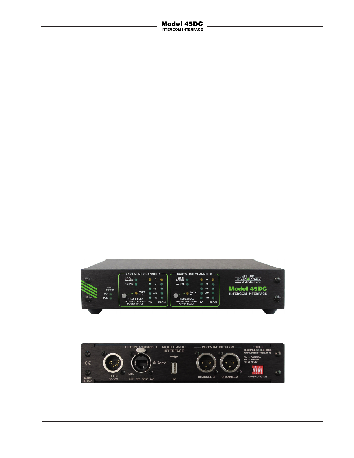
Figure 1. Model 45DC standard “throw-down” front view
Figure 2. Model 45DC back view
Model 45DC User Guide Issue 1, January 2015
Studio Technologies, Inc. Page 5
Page 6

can also connect with one or two existing
powered and terminated intercom circuits.
Audio level meters provide confirmation
of system performance during setup and
operation. Support for transporting call
light signals between Model 45DC units is
also provided.
Standard connectors are used for partyline intercom, Ethernet, and DC power
interconnections. The Model 45DC’s
enclosure has a “1/2-rack” 1U form factor
and weighs less than two pounds, making
it well suited for use in portable applications. Alternately, using one of the optional
rack-mount front panels, one or two Model
45DC units can be mounted in a single
space (1U) of a standard 19-inch rack
enclosure.
Applications
There are two main ways that the Model
45DC can be used in applications. The
first is to add party-line intercom support
for matrix intercom systems. The second
is to link two stand-alone party-line intercom systems. Ports on matrix intercom
systems that support Dante, such as the
RTS ADAM with OMNEO, can be routed to
the Model 45DC’s Dante input (receiver)
and output (transmitter) channels. The
Model 45DC’s circuitry will then convert
these signals into two single-channel party-line intercom circuits. In this way adding
party-line support to RTS + OMNEO is a
simple task. The Model 45DC can also be
used with matrix intercom systems that
don’t support Dante. An external analogto-Dante interface can be used to convert
analog intercom ports to Dante channels.
Once in the digital domain, these Dante
channels can be interconnected with the
Model 45DC’s audio input and output
channels.
Two separate sets of party-line intercom
circuits can easily be interconnected using
two Model 45DC Interfaces. At each end
a Model 45DC is connected to one or two
party-line circuits as well as the Dante
network. The Dante Controller application will then be used to route the audio
channels between the two units. That’s
it — nothing else is required to achieve
excellent performance.
The Model 45DC can also be used to
“bridge” two single-channel party-line
intercom circuits with one 2-channel partyline intercom circuit. This involves using
a Model 45DC for the two single-channel
circuits and one of the Studio Technologies Model 45DR Intercom Interface units
for the 2-channel circuit. The Model 45DR
is the “cousin” of the Model 45DC and
supports one 2-channel party-line intercom circuit rather than two single-channel
circuits. These 2-channel circuits, typically
supported by equipment from RTS, are
commonly used in broadcast applications.
Party-Line Interfaces
The Model 45DC’s two party-line intercom
interfaces are optimized for connection
with two single-channel party-line circuits
and user devices such as those associated with equipment from Clear-Com. (While
the Model 45DC will function in a limited
manner with a 2-channel RTS TW circuit,
the Model 45DR Intercom Interface is the
much-preferred choice.) Each interface
has a party-line active detection function
to ensure that should a beltpack or active party-line circuit not be connected
the Model 45DC’s interface circuitry will
remain stable. This unique feature makes
certain that objectionable audio signals,
including oscillations and “squeals,” won’t
be sent to other Dante-enabled devices.
Issue 1, January 2015 Model 45DC User Guide
Page 6 Studio Technologies, Inc.
Page 7

A significant capability of the Model 45DC’s
two party-line intercom interfaces is their
ability to supply DC power and 200 ohm
AC terminations to “create” two independent intercom circuits. The 28 volt DC
output can power user devices such as
beltpacks. With up to 150 milliamperes
(mA) of current available, a typical entertainment application could connect up to
three RS-501 or five RS-701 beltpacks to
each of the Model 45DC’s two interfaces.
In many applications this can eliminate the
need for an external intercom power supply, thereby reducing total system cost,
weight, and required mounting space. The
power supply outputs are monitored for
over-current and short-circuit conditions.
Under firmware (embedded software)
control the outputs will automatically cycle
off and on to help prevent damage to the
circuitry and connected equipment.
Dante Audio-over-Ethernet
Audio data is sent to and from the Model
45DC using the Dante Audio-over-Ethernet
media networking technology. Audio
signals with a sample rate of 48 kHz and
a bit depth of up to 24 are supported.
Audio input (receiver) and output (transmitter) channels on associated Dante-enabled
devices can be assigned to the Model
45DC using the Dante Controller software
application. This makes selecting the way
in which a Model 45DC fits into a specific
application a simple matter.
Analog Hybrids with Auto
Nulling
Two circuits referred to as “hybrids” interface the Dante input and output channels
with the two party-line interface channels.
The hybrids provide low noise and distortion, good frequency response, and high
return-loss (“nulling”), even when presented
with a wide range of party-line conditions.
Unlike telephone-line (“POTS”) oriented
DSP-based hybrid circuits, the Model
45DC’s analog circuitry maintains extended
frequency response. With a passband of
100 Hz on the low end and 8 kHz on the
high end, natural-sounding voice signals
can be sent to and received from a partyline circuit.
The Model 45DC’s sophisticated hybrid
auto nulling function uses a combination
of digital and analog circuitry under microprocessor control to achieve significant
trans-hybrid loss. This return-loss “null” is
achieved by making a series of firmwaredirected adjustments to account for the resistive, inductive, and capacitive conditions
that are present on the connected party-line
cabling and user devices. Whenever one
of the Model 45DC’s auto null buttons is
pressed digital circuitry adjusts the associated hybrid to achieve its maximum returnloss in less than 15 seconds. While the
nulling process is automatic, it only takes
place upon user request. The resulting
null parameters are stored in non-volatile
memory.
Pro Audio Quality
The Model 45DC’s audio circuitry was designed in the spirit of professional
audio equipment rather than that found
in typical party-line intercom gear. High-performance components are used throughout, providing low-distortion, low-noise, and
high headroom. Using passive and active
filters the frequency response of the audio
channels is limited to nominally 100 Hz to
8 kHz. This range was selected to provide
excellent performance for human speech
while maximizing the ability of the hybrid
circuits to create substantial “nulls.”
Model 45DC User Guide Issue 1, January 2015
Studio Technologies, Inc. Page 7
Page 8

Audio Meters
The Model 45DC contains two sets of 5segment LED level meters. Each set of
two meters displays the level of the signals
being sent to and received from a party-line
interface channel. At the time of installation and setup the meters are invaluable in
helping to confirm correct operation. During
normal operation the meters offer rapid confirmation of audio signals flowing in to and
out of the unit. Additional LED indicators are
also provided on the front panel, offering a
status indication of the party-line DC power
sources, party-line activity status, and the
auto null functions. Two other LEDs offer a
direct indication of which source is powering
the Model 45DC.
Call Light Support
Typical single-channel party-line intercom
circuits provide a call light function by way
of a DC voltage applied to the audio path.
The Model 45DC can detect call light activity, convert it to a 20 kHz audio tone, and
transport the tone over the Dante audio
path. A Model 45DC unit at the “far end”
will detect the tone and re-generate the call
signal as a DC voltage on the audio path.
This allows full “end-to-end” call light support between two or more Model 45DC
units. It also allows a Model 45DC to send
and receive call light status with an interconnected Model 45DR Dante to 2-Channel
Party-Line Intercom Interface. The Model
45DR is typically used with the RTS TWseries of party-line user beltpacks including
the popular BP-325.
Ethernet Data, PoE, and DC
Power Source
The Model 45DC connects to a data network using a standard 100 Mb/s twisted-pair
Ethernet interface. The physical interconnection is made by way of a Neutrik®
etherCON RJ45 connector. While compatible with standard RJ45 plugs, etherCON
allows a ruggedized, locking interconnection for harsh or high-reliability environments. The Model 45DC’s operating power
can be provided by way of the Ethernet
interface using the Power-over-Ethernet
(PoE) standard. This allows fast and efficient interconnection with the associated
data network. To support PoE power management, the Model 45DC’s PoE interface
reports to the power sourcing equipment
(PSE) that it is a class 3 (medium power)
device. The unit can also be powered
using an external source of 12 volts DC.
For redundancy, both power sources can
be connected simultaneously. An internal
switch-mode power supply ensures that all
Model 45DC features, including party-line
intercom circuit power, are available when
the unit is powered by either source. Four
LEDs on the back panel display the status
of the network connection, Dante interface,
and PoE power source.
Simple Installation
The Model 45DC uses standard connectors to allow fast and convenient interconnections. An Ethernet signal is connected
using a Neutrik etherCON RJ45. If Powerover-Ethernet (PoE) is available operation
will commence immediately. An external
12 volt DC power source can also be connected by way of a 4-pin XLR. Party-line
intercom connections are made using two
3-pin male XLR connectors. The Model
45DC is housed in a rugged yet lightweight
aluminum enclosure that is designed to be
“field tough.” It can be used as a standalone portable unit, supporting what’s
Issue 1, January 2015 Model 45DC User Guide
Page 8 Studio Technologies, Inc.
Page 9

known in the broadcast world as “throwdown” applications. Rack-mount options
are also available allowing one or two
units to be mounted in one space (1U) of
a standard 19-inch rack enclosure.
Future Capabilities and
Firmware Updating
The Model 45DC was designed so that its
capabilities can be enhanced in the future.
A USB connector, located on the Model
45DC’s back panel, allows the application firmware (embedded software) to be
updated using a USB flash drive. To implement the Dante interface the Model 45DC
uses Audinate’s Ultimo™ integrated circuit. The firmware in this integrated circuit
can be updated via the Ethernet connection, helping to ensure that its capabilities
remain up to date.
Installation
In this section signal interconnections will
be made using the connectors located on
the back panel of the Model 45DC. Connections to one or more party-line user
devices or one or two existing party-line
intercom circuits will be made using the
3-pin XLR connectors. An Ethernet data
connection will be made using either a
standard RJ45 patch cable or an etherCON protected RJ45 plug. A 4-pin XLR
connector allows the connection of an
external source of 12 volts DC.
System Components
Included in the shipping carton are the
Model 45DC Intercom Interface and a user
guide. If a rack-mount front panel is going
to be used as part of the installation it will
typically be shipped in a separate carton.
If the installation or specific application requires an external source of 12 volts DC it
needs to be provided separately. An applicable power supply, the Studio Technologies PS-DC-02, is available as an option.
Locating the Model 45DC
The location of the Model 45DC will depend on the length of the cable runs
needed to link the unit with the associated
party-line intercom devices. This type of
circuit carries unbalanced audio which can
be susceptible to interference and crosstalk issues. And since party-line intercom
circuits typically carry DC power a voltage
drop due to resistive loss can become an
issue. In general, minimizing the length
of the party-line intercom cables will help
ensure more reliable and consistent intercom system performance. Of equal importance is the 100-meter (325-foot) Ethernet
cable limitation. A final location criterion is
to ensure that access to the Model 45DC’s
front panel is available. An optimal location
will allow convenient use of the auto null
pushbutton and easy observation of the
status and level meters LEDs.
Protecting the Enclosure
The Model 45DC is shipped as a selfcontained unit suitable for portable use
or placement in a semi-permanent location. Installed on the bottom of the chassis
are screw-on “bump on” protectors (also
known as “rubber feet”). These are useful
if the unit is going to be placed on surfaces
where scratching of either the Model 45DC
or the surface material could take place.
The “feet” can be removed, without the use
of a tool, when rack- or custom-mounting
the unit.
Model 45DC User Guide Issue 1, January 2015
Studio Technologies, Inc. Page 9
Page 10

Rack Mounting the Model
45DC
For permanent or mobile applications it
might be desirable to mount one or two
Model 45DC units into one space (1U) of
a 19-inch rack enclosure. Two rack-mount
front panels, purchased separately, are
available from Studio Technologies. The
following provides details on how to install
and use the panels.
Mounting a Model 45DC to a dual-unit
rack-mount panel follows the same procedure but will apply to two units. Store both
of the removed standard front panels and
the eight “bump on” protectors for possible later use. Note that on the rack-panels
graphics the unit on the left is designated
as A while the unit on the right is designated as B. This is provided so that each
can be easily identified during installation,
troubleshooting, and operation.
To attach a Model 45DC unit to the singleunit rack-mount panel, begin the process
by using a 5/64-inch hex wrench to remove
the four 4-40 thread hex-head machine
screws that hold the standard front panel
to the chassis. Note that the screws might
be quite tightly affixed. Ensure that a goodquality hex wrench is used and press and
hold it firmly while turning counterclockwise. Unless this recommendation is followed the wrench can “cam out” and the
head could be “stripped.”
Using the screws that were just removed,
attach the rack-adapter front panel to the
Model 45DC’s chassis. To prevent damage
care is required when aligning the front
panel with the LEDs and auto null pushbutton switch that protrude through both
the Model 45DC’s chassis and front panel.
Tighten the four screws only after a careful
inspection ensures that the switch and all
28 of the LEDs protrude through the front
panel without interference. To allow vertical
clearance in the associated rack, remove
the four “bump on” protectors from the
bottom of the chassis. They are removed
by using the fingers to rotate them counter-clockwise; no tool is required. Carefully
protect and store the standard front panel,
along with the “bump on” protectors, for
possible later use.
Once the desired one or two Model 45DC
units have been installed in a rack-mount
front panel, the assembly can be mounted into the designated equipment rack.
One space (“1U” or 1.75 vertical inches)
in a standard 19-inch equipment rack
is required. Secure the front panel into
the equipment rack using two mounting
screws per side.
Ethernet Connection
An Ethernet connection that supports
100BASE-TX (100 Mb/s over twisted-pair) is
required for the Model 45DC’s Dante Audio-over-Ethernet connectivity. A 10BASE-T
connection is not sufficient for Model 45DC
operation. A 1000BASE-T (“GigE”) connection is not supported unless it can automatically “fall back” to 100BASE-TX operation.
An Ethernet connection that supports
Power-over-Ethernet (PoE) is preferred as it
will provide operating power for the Model
45DC. To support PoE switch (PSE) power
management the Model 45DC will enumerate itself as a PoE class 3 device. If PoE is
not available an external 12 volt DC power
source can be connected. This will be discussed in the next section of this guide.
The 100BASE-TX Ethernet connection is
made by way of a Neutrik etherCON protected RJ45 connector that is located on
Issue 1, January 2015 Model 45DC User Guide
Page 10 Studio Technologies, Inc.
Page 11

the back panel of the Model 45DC. This
allows connection by way of a cablemounted etherCON plug or a standard
RJ45 plug. The Model 45DC’s Ethernet
interface supports auto MDI/MDI-X so
that most cabling implementations will
be correctly supported.
External 12 Volt DC Input
An external source of 12 volts DC can be
connected to the Model 45DC by way of a
4-pin male XLR connector which is located
on the back panel. While the requirement
for the external source is to be nominally
12 volts, correct operation will take place
over a 10 to 18 volt range. The Model 45DC
requires 1.0 amperes maximum for correct operation. The DC source should be
terminated to a 4-pin female XLR connector
with pin 1 negative (–) and pin 4 positive
(+). Purchased as an option, the PS-DC-02
power supply is available from Studio Technologies. Its AC mains input allows connection to 100-240 volts, 50/60 Hz and its 12
volt DC, 1.5 amperes maximum output is
terminated on a 4-pin female connector.
As previously discussed in this guide, an
Ethernet connection that provides Powerover-Ethernet (PoE) can serve as the Model
45DC’s power source. Alternately, an external 12 volt DC source can be connected.
For redundancy, both PoE and the external
12 volt DC source can be connected at
the same time. If both PoE and an external
12 volt DC source are connected, power
will be drawn only from the PoE supply. If
the PoE source becomes inoperative the
12 volt DC source will provide the Model
45DC’s power with no interruption in operation. (Of course, if both PoE and Ethernet
data support are lost that is a very different
situation!)
Party-Line Intercom
Connections
The Model 45DC’s party-line intercom
interface is designed to function in two
distinct ways. It can be connected to one
or two “powered” broadcast-standard
2-channel party-line intercom circuits or
directly to one or two sets of party-line
intercom user devices. A single-channel
party-line intercom circuit, such as frequently associated with equipment from
Clear-Com, has DC power and one audio
channel on a 3-pin XLR connector. The
connector is wired such that common is
on pin 1, 22 to 30 volts DC is on pin 2,
and audio is on pin 3. An impedancegenerating network provides a 200 ohm
audio load from pin 3 to pin 1. When the
Model 45DC’s party-line interfaces are
connected to existing intercom circuits
they act, from an audio standpoint, as
standard user devices. They don’t draw
(nor supply) any DC power.
The Model 45DC’s two party-line interfaces can serve to create two “mini” intercom circuits. They each provide a 28
volt DC intercom power source and a 200
ohm impedance generator, allowing a
limited number of single-channel intercom
user devices to be directly connected.
The Model 45DC’s two internal 28 volt DC
power sources each have a maximum
current of 150 mA. This modest amount
of power can be very useful but requires
that the type and number of connected
user devices be selected appropriately.
Many entertainment applications use
the legacy Clear-Com RS-501 beltpack
and each Model 45DC intercom circuit
can directly support up to three of them.
With the newer and more energy efficient
Clear-Com RS-701 it should be possible
Model 45DC User Guide Issue 1, January 2015
Studio Technologies, Inc. Page 11
Page 12

to connect up to five of them. Wiring from
the Model 45DC intercom interface’s 3-pin
male XLR connectors to the user devices
requires that a 1-to-1, 2-to-2, 3-to-3 wiring
scheme on the mating 3-pin XLR connectors be maintained.
Compatibility with 2-Channel
Intercom Systems
As previously discussed in this guide, the
Model 45DC is designed to support singlechannel party-line intercom circuits and
user devices. It’s possible that applications
that involve 2-channel party-line intercom
circuits and user devices (typically associated with the RTS TW-series of products)
can also be supported. These circuits and
devices typically utilize common on pin 1,
28 to 32 volts DC and channel 1 audio on
pin 2, and channel 2 audio on pin 3. When
connected to a Model 45DC only channel
2 will be active; channel 1 would not be
utilized. A better means to support these
2-channel circuits and devices is to use the
Studio Technologies Model 45DR Interface.
This unit, the “cousin” of the Model 45DC,
is optimized for 2-channel party-line intercom applications. Rather than providing
two single-channel interfaces the Model
45DR provides one 2-channel interface.
Detailed information about the Model 45DR
is available on the Studio Technologies, Inc.
website (www.studio-tech.com).
Model 45DC’s call light support function to
be disabled. Switches 2-4 are not currently
utilized and have no impact on Model
45DC operation.
Call Light Support
When switch 1 is in its off (down) position
the call light support function is enabled.
When switch 1 is in its on (up) position
the function is disabled. For most applications the call light support function
should remain enabled. Only special
circumstances would merit disabling the
function. Note that the call light function
between user devices connected to the
same Model 45DC interface will always
be active. Disabling the Model 45DC’s call
light support function only impacts the call
function that’s sent and received by way of
the Dante audio connections.
Figure 3. Call light support configuration switch
Dante Configuration
To integrate the Model 45DC into an application a number of Dante-related param-
Configuration
Back-Panel DIP Switches
A 4-position DIP switch assembly, labeled
Configuration, is located on the Model
45DC’s back panel. Switch 1 allows the
Issue 1, January 2015 Model 45DC User Guide
Page 12 Studio Technologies, Inc.
eters can be configured. At a minimum,
the audio input (receiver) and audio output (transmitter) channels must be routed.
The configuration settings will be stored
in non-volatile memory within the Model
45DC’s circuitry. The Model 45DC uses
the Ultimo 2-input/2-output integrated
Page 13

circuit to implement the Dante architecture.
This dictates which parameters can be configured and what choices are available.
The audio input (receiver) and output
(transmitter) channels associated with the
Model 45DC’s Dante interface must be
assigned to desired sources and destinations. This will typically be done with the
Dante Controller software application which
is available for download free of charge at
www.audinate.com. Versions are available
to support Windows® and OS X® operating systems. Within Dante Controller a
“subscription” is the term used for routing
a transmitter flow (a group of output channels) to a receiver flow (a group of input
channels). Note that as of the writing of this
guide the Ultimo integrated circuit limits
the number of Dante flows to two in each
direction (two transmitter and two receiver).
These can either be unicast, multicast, or a
combination of the two.
The Model 45DC has a default Dante
device name of ST-M45DC followed by
a unique suffix. The suffix identifies the
specific Model 45DC that is being configured; it relates to the MAC address of the
unit’s Ultimo integrated circuit. The Model
45DC provides two Dante transmitter (output) channels with the default names of
From PL Ch1 and From PL Ch2. The
Model 45DC has two Dante receiver (input)
channels with default names of To PL Ch1
and To PL Ch2. Using Dante Controller
these names can be revised as appropriate
for the specific application.
The Model 45DC only supports an audio
sample rate of 48 kHz but does have the
ability to select a pull-up/pull-down value.
This value can be selected using the Dante
Controller application. The Model 45DC
can serve as the clock master for a Dante
network but in most cases that would not
be optimal.
Model 45DC units will typically be used in
either of two configurations: “point-to-point”
or in association with other Dante-enabled
equipment. The first configuration finds two
units working together to “link” two physical
locations. At each location there will either
be one or two existing party-line intercom
circuits or one or two sets of user devices.
The two Model 45DC units will be operating “point-to-point,” interconnected by way
of the associated Ethernet network. For
this application the audio routing would be
very simple. To PL Ch1 on each unit would
be routed to From PL Ch1 on the other
unit. And To PL Ch2 on each unit would be
routed to From PL Ch2 on the other unit.
The other typical applications will have one
Model 45DC connected to one or two existing party-line intercom circuits or supporting one or two sets of user devices. The
unit’s audio channels would be routed to
input and output audio channels on associated Dante-enabled equipment. For example, the RTS ADAM matrix intercom system
provides Dante interconnection capability
using its OMNEO interface card. The audio channels on the Model 45DC would
be routed to and from audio channels on
the OMNEO card. Other equipment that
supports Dante, such as audio consoles
or audio interfaces (Dante-to-MADI, Danteto-SDI, etc.), can have their audio channels
routed to and from a Model 45DC.
Model 45DC User Guide Issue 1, January 2015
Studio Technologies, Inc. Page 13
Page 14

Operation
At this point the Model 45DC should have
its party-line and Ethernet connections
made. Depending on the application an
external 12 volt DC power connection may
have also been made. The Dante input
(receiver) and output (transmitter) channels
should have been routed using the Dante
Controller software application. Normal operation of the Model 45DC can now begin.
Initial Operation
The Model 45DC will begin functioning a
few seconds after its power source is connected. As previously discussed, the power
source can be provided by Power-overEthernet (PoE) or an external source of
12 volts DC. If both are connected the PoE
source will power the unit. Should PoE subsequently no longer be available, operation
will continue using the external source.
Upon Model 45DC power up many of
the status and meter LEDs will activate in
test sequences. The PoE and USB LEDs,
located on the back panel, will light one
after another. On the front panel the input
power, channel status and level meters
LEDs will light in a sequence. Once the test
sequences have completed two columns
of front-panel level meter LEDs will momentarily display the version number of the
unit’s application firmware. Details on how
to “read” the version number is provided in
the Technical Notes section of this guide.
The Model 45DC will now begin normal
operation. The way in which the LINK/ACT,
SYS, SYNC, and PoE LEDs (all located on
the back panel below the Ethernet connector) light will depend on characteristics
related to the connected Ethernet signal
and the configuration of the unit’s Dante
interface. Details will be covered in the next
paragraph. The user is presented on the
front panel with two pushbutton switch, two
input power status LEDs, six channel status
LEDs, and four 5-segment LED level meters. These resources are simple to operate
and understand, as will be described in
later paragraphs.
Ethernet, PoE, and Dante
Status LEDs
Four status LEDs are located below the
Ethernet connector on the Model 45DC’s
back panel. The LINK/ACT LED will light
green whenever an active connection to a
100 Mb/s Ethernet network has been established. It will flash on and off in response to
data packet activity. The PoE LED will light
green whenever Power-over-Ethernet (PoE)
associated with the connected Ethernet
signal is providing operating power for the
Model 45DC. The SYS and SYNC LEDs
display the operating status of the Dante
interface and associated network. The SYS
LED will light red upon Model 45DC power
up to indicate that the Dante interface is
not ready. After a short interval it will light
green to indicate that it is ready to pass
data with another Dante device. The SYNC
LED will light red when the Model 45DC is
not synchronized with a Dante network. It
will light solid green when the Model 45DC
is synchronized with a Dante network and
an external clock source (timing reference)
is being received. It will slowly light on and
off green when the Model 45DC is part of
a Dante network and is serving as a clock
master.
Issue 1, January 2015 Model 45DC User Guide
Page 14 Studio Technologies, Inc.
Page 15

How to Identify a Specific
Model 45DC
The Dante Controller software application
offers an identify command that can be
used to help locate a specific Model 45DC.
When identify is selected for a specific
unit the SYS and SYNC LEDs on that unit
will together light slowly on and off green.
This makes it a simple task to observe the
selected Model 45DC unit.
Level Meters
The Model 45DC contains four 5-segment
LED level meters. These meters are provided as a support aid during installation,
configuration, operation, and troubleshooting. The meters represent the strength of
the audio signals going to and coming
from the two party-line intercom interfaces.
General
Each interface has two meters associated
with it, one represents audio being sent to
the party-line circuit and the other representing audio coming from the party-line
circuit. The meters are calibrated to reflect
the level in dB relative to the reference
(nominal) level of the party-line circuit. In
the case of the Model 45DC the nominal
level of the party-line was selected to be
–14 dBu since that matches that of the typical single-channel party-line circuit. (Very
early single-channel Clear-Com systems
had a nominal level of -20 dBu but that’s
no longer true for contemporary units.)
As an example of how the meters function
let’s review the situation where the channel
A TO meter has its bottom three LEDs
(–18, –12, and –6) lit solid and its 0 LED
just barely lighting. This would indicate
that a signal with an approximate level of
–14 dBu is being sent to the associated
party-line intercom circuit. (Also note that
this –14 dBu signal on the party-line in
tercom circuit will translate to a –20 dBFS
digital audio signal on the Dante interface.
This is due to Studio Technologies selecting –20 dBFS as the reference (nominal)
level for Dante.)
Each level meter contains four green LEDs
and one yellow LED. The four green LEDs
indicate party-line circuit signal levels at or
below –14 dBu. The top LED is yellow and
indicates a signal that is 6 dB or greater
than the –14 dBu nominal level. An audio
signal that causes the yellow LED to light
doesn’t necessarily indicate an excessive
level condition, but it does provide a warning that at some stage reducing the signal
level may be prudent. Typical operation
with normal signal levels should find the
meters lighting near their 0 point. Signal
peaks may cause the yellow LEDs to flash.
But a yellow LED that lights fully during
normal operation will typically indicate excessive signal level and/or a configuration
problem with associated Dante-enabled
equipment.
Non-Optimal Signal Levels
If the meters consistently display levels
that are lower or higher than the 0 (reference) point it’s possible that a configuration issue exists. This would typically be
related to incorrect settings on the equipment connected to the associated Dante
input and output channels. (This situation
is almost impossible to occur if two Model
45DC units were configured “point-topoint” as no Dante digital audio level
adjustment is provided.) With a digital
matrix intercom system this problem could
be due to an incorrect configuration having been made to a specific channel or
port. For example, the RTS ADAM system
-
Model 45DC User Guide Issue 1, January 2015
Studio Technologies, Inc. Page 15
Page 16

has a published nominal level of +8 dBu,
but it’s not clear how this translates into a
digital audio level on an associated Dante
channel. Using its configuration software
it’s most likely possible to set the nominal
level of intercom key panels or ports to
something different than +8 dBu. The best
solution in this case would be to adjust the
associated OMNEO (Dante-compatible)
port such that it results in a nominal level of
–20 dBFS on the associated Dante channels. This should lead to the best performance of the Model 45DC and associated
party-line user devices.
Audio Levels and Party-Line Termination
The FROM meters display the level of signals that come from the party-line circuit.
These signals are then sent as digital audio
to the associated Dante output channels.
An issue may arise if the signals coming
from the connected party-line circuit or user
devices aren’t at a sufficient level so that a
normal meter display level can be reached.
For a party-line circuit to function correctly
the impedance (resistance to AC signals
such as audio) must be approximately 200
ohms. Typically to achieve this depends
on a single piece of equipment providing
a single audio termination. This termination, 200 ohms nominally, is almost always
made at the power supply source. But it’s
possible that another device, such as a
second active power supply on the same
party-line circuit, will cause a “doubletermination” condition. This will result in
a 100 ohm party-line circuit impedance and
an audio level drop of about 6 dB. Removing the unwanted termination is the only
valid means of correcting the problem.
In most cases this will be simple to solve.
It’s easily possible for the Model 45DC’s
local power source, which also provides
200 ohm termination networks for the
audio channel, to be enabled when the
Model 45DC is connected to an externallypowered party-line circuit. This would
be incorrect, leading to the “doubletermination” condition. Turning off the
Model 45DC’s local power source by
pressing and holding the auto null button
is all that is required.
Power Status LEDs
Two green LEDs are located on the front
panel and are associated with operating
power. The PoE LED indicator will light
whenever an Ethernet connection with
Power-over-Ethernet (PoE) capability is
connected. The DC power LED will light
whenever an external DC voltage has
been applied. The acceptable range is 10
to 18 volts DC. If both power sources are
present the PoE source will provide the
Model 45DC’s operating power.
Party-Line Operating Mode
Selection
As discussed previously in this guide, the
Model 45DC provides two main operating
modes. One mode is used when a Model
45DC channel is required to create a party-line circuit, providing 28 volts DC and
a 200 ohm termination impedance. In this
mode user devices such as beltpacks can
be directly supported. When this mode
is selected the local power status LED
will be lit. The second mode allows the
Model 45DC to be connected to an existing powered party-line intercom circuit. In
this mode the local power status LED will
not be lit. To select the desired operating
mode is simple, only requiring the audio
Issue 1, January 2015 Model 45DC User Guide
Page 16 Studio Technologies, Inc.
Page 17

null pushbutton switch of the desired interface channel to be pressed and held for two
seconds. The mode will change and the local power LED will display accordingly. The
button can then be released. The selected
operating mode for each interface channel
will be stored in non-volatile memory so that
they will restore after a power-down/powerup cycle.
Local Power Mode Operation
When a channel’s local power LED is lit the
Model 45DC provides party-line power and
a 200 ohm termination impedances to create a single-channel party-line circuit. The
party-line interface supplies 28 volts DC on
pin 2 of the 3-pin XLR connectors. A maximum current draw of 150 mA per interface
is available. This current is sufficient to power intercom user devices such as beltpacks.
A common entertainment or corporate
application might use Clear-Com RS-501
or RS-701 beltpacks. Select the connected
devices so that their total maximum current
doesn’t exceed 150 mA. That’s not always
the easiest figure to calculate but a web
search will generally find specifications for
all commonly used devices. For example, a
search finds that the ubiquitous RS-501 will
consume a maximum of 50 mA of current.
According to this figure up to three of these
units can be connected to a Model 45DC. A
newer version, the RS-701 has a quiescent
current draw of 12 mA and an approximate
maximum of 23 mA. From this information
one could estimate that up to five of these
units can easily be supported.
The active LED will light when a minimal
amount of current is flowing from the Model
45DC intercom interface to the connected
user device or devices. This current,
approximately 5 mA, provides a “circuitactive” signal to the Model 45DC’s firmware, indicating that normal operation
is taking place. This helps to prevent unwanted audio signals from passing to and
from the Dante audio channels when no
party-line devices are connected.
The Model 45DC’s two party-line intercom
power supply circuits operate independently under firmware control. This allows
detection of fault conditions and protection of the Model 45DC’s circuitry. Upon
initial Model 45DC party-line intercom
power up no monitoring of the intercom
power outputs takes place for three seconds. This allows the Model 45DC’s circuitry and the connected intercom user
devices to stabilize. The active LEDs,
which monitor the DC voltage on pin 2 of
the 3-pin XLR connectors associated with
the intercom channels, will light to indicate
that an output is active. After this initial
delay period monitoring becomes active.
A fault condition is detected if the voltage
on pin 2 falls below 24 for a continuous
1-second interval. The hardware and firmware responds to this condition by turning
off the associated power source to pin 2
and flashing the active LED as a warning.
After a 5-second “cool-down” interval the
output returns to the same condition as
upon initial power up. Power is again
applied to pin 2, the active LED will light,
and monitoring won’t begin for another
three seconds. A full short-circuit condition
applied to either of the Model 45DC’s
party-line circuits will result in a continuous cycle of four seconds on (three
seconds for start up and one second for
detection) and five seconds off on that
specific circuit.
Model 45DC User Guide Issue 1, January 2015
Studio Technologies, Inc. Page 17
Page 18

External Party-Line Circuit
Operation
When an interface channel’s local power
LED is not lit that interface is intended to
be connected to an external party-line
circuit. The external circuit must provide
power and termination impedances to
“create” the party-line, with the Model
45DC simply serving as a user device.
When connected to an external party-line
circuit the active LED associated with that
interface channel will light when the voltage on pin 2 is equal to or greater than approximately 18. If this condition is present
then normal Model 45DC operation will be
able to take place.
Auto Null
The Model 45DC contains circuitry to
automatically null the hybrid networks associated with the two party-line interfaces.
This procedure minimizes the mixing of
the audio signals being received by and
sent to each party-line interface circuit.
Normally the nulling processes are performed at the time of initial Model 45DC
configuration but there’s no reason why either or both can’t be initiated any time one
desires. The only time that an auto null
must be performed is if conditions have
changed with the party-line user devices
and wiring connected to a Model 45DC’s
party-line connector. Even a small change
to a party-line intercom circuit, such as
adding or removing a section of cable, is
often enough to require that the auto null
process be performed.
Two pushbutton switches are provided
to activate the auto null process for each
interface. To initiate auto null first requires
that an interface’s active LED be lit. When
an interface’s operating mode is set for
local power the active LED will light when
current is flowing from the internal power
supply. When the local power LED is not lit
the active LED must be lit, indicating that
sufficient DC voltage is present on pin 2
of the connected party-line circuit. Once
the active LED is lit initiating an auto
null function only requires pressing and
releasing (“tapping”) the appropriate auto
null button. An LED provides a visual indication of the status of the auto null process,
flashing when the auto null process is active. If the auto null button is pressed when
its associated active LED is not lit the auto
null process will not start. The auto null
LED will quickly flash on and off a few times
to indicate this condition. Only one auto
null process can be active at any one time.
Nothing will happen if either auto null button is pressed when the auto null process
is active for an interface. (An interface’s
mode can be changed when the auto null
is active on the other interface.)
An auto null sequence begins in this manner: If local power is being provided to the
party-line interface by the Model 45DC it
will momentarily turn off and then turn on
again. This will act as a “mic kill” signal,
ensuring that microphones associated
with the connected user devices will be
placed in their off state. Then the audio
input and output signal paths associated
with the Dante input and output channels
will mute. Next a series of tones will be
sent to the party-line interface’s audio path.
Other Model 45DC circuitry, under firmware
control, will rapidly perform adjustments to
achieve the best null possible. After the adjustments have been made the results are
stored in non-volatile memory. Once the
process is complete the Dante audio input
and output paths are again activated.
Issue 1, January 2015 Model 45DC User Guide
Page 18 Studio Technologies, Inc.
Page 19

If possible, prior to performing an auto null
it’s polite to warn all personnel who are actively using connected party-line intercom
devices. The tones sent to the party-line
circuit during the nulling process are not
excessively loud or obnoxious, but most
users might want to remove their headsets
during the process. In addition to warning
users, it’s a good idea to ask them to mute
any active microphones. Muting the microphones can be significant as obtaining
a “deep” null requires that no extraneous
signals be present on the intercom circuit.
As previously discussed, if the Model 45DC
is supplying local intercom power the microphones will automatically be muted. But
for applications that connect to an existing
party-line intercom circuit the user’s must
manually mute the microphones.
The Model 45DC provides a call light support function, allowing call light signals
associated with user devices on two Model
45DC interfaces to work together. The
function also allows a Model 45DC interconnected with a Model 45DR Dante to
2-Channel Party-Line Intercom Interface to
have common call light activity. No operator action is required for the call light support function to perform its task. However,
placing DIP switch 1, located on the back
panel, to its on (up) position will disable the
function.
USB Interface
A USB type A connector and associated
status LED is located on the back panel of
the Model 45DC. This data interface is used
only for updating the unit’s application firmware. No audio data of any kind will pass
through it. For details please refer to the
Technical Notes section of this guide.
Technical Notes
Call Light Support
A “call” or “call light” indication on a ClearCom party-line intercom circuit is transmitted by way of a DC voltage that is applied
to the audio path, which is typically pin 3
of the interconnecting cable. This DC voltage is summed (added) to any audio that
is present. The Model 45DC detects when
a call light signal is active by monitoring the
audio path for the presence of a DC voltage.
A signal of approximately 5 Vdc or greater
is needed to indicate that the call function
is active. The Model 45DC can also generate a call signal by applying a DC voltage to
audio path. The DC, approximately 16 V, is
ramped up and down to minimize the addition of clicks or pops to the audio signal.
While the Model 45DC can detect and generate a call signal, it’s not possible to directly send and receive these DC signals over a
Dante interconnection that’s intended only
for audio transport. The Model 45DC works
around this issue by converting the DC call
light signaling to one that’s based on a 20
kHz audio tone. An astute user will recognize this as the call method used by the TWseries from RTS; instead of signaling via DC
in the audio path a 20 kHz signal is used.
In the “telco” world this would be referred
to as in-band signaling, not dissimilar to the
touch-tone dialing method that’s used on
analog telephone lines. But unlike touchtone signals, a 20 kHz signal has the advantage of being above the hearing range of
most humans. This allows normal intercom
audio and a 20 kHz call signal to be active
simultaneously. And transporting this combined talk/call signal over the Model 45DC’s
Dante connection shouldn’t be a problem
as a digital audio path that has a 48 kHz
Model 45DC User Guide Issue 1, January 2015
Studio Technologies, Inc. Page 19
Page 20

sample rate can easily transport a 20 kHz
signal.
When the Model 45DC detects DC on the
audio path (pin 3 of the back-panel interface connector) it will digitally generate
a 20 kHz tone and mix (sum) it with any
audio signals present on the associated
Dante output (transmit) channel. Detection
circuits in the Model 45DC’s Dante input
(receive) audio paths continually monitor
for the presence of a 20 kHz tone. If this
signal is detected (in the digital domain)
it will cause a DC voltage to be applied to
the audio path of the associated party-line
interface circuit. When the 20 kHz signal
is no longer present the DC voltage will
be removed. The 20 kHz-to-DC translation
takes place automatically with no configuration required. This method is very useful for a number of reasons. It allows two
Model 45DC units that are interconnected
in a point-to-point manner to transport both
audio and call signals between them. It will
also allow the support of call signals between a Model 45DC (supporting two single-channel Clear-Com party-line circuits)
and a Model 45DR (supporting a 2-channel
RTS party-line circuit). And finally it will allow equipment that’s capable of transporting 20 kHz call signals associated with RTS
party-line circuits, such as RTS ADAM OMNEO ports, to send and receive DC-based
call signals associated with single-channel
Clear-Com party-line devices.
Note that digital filters in the Model 45DC’s
firmware prevent essentially all information
above 10 kHz from being sent to the partyline audio channels. This helps to ensure
that the hybrid circuits provide a “deep”
null as was as keeping the 20 Hz call signal
from each party-line audio path.
Common Ground
The Model 45DC provides two independent
single-channel party-line intercom interfaces.
These interfaces can be connected to two
sets of user devices, two existing party-line
intercom circuits, two channels from an
external party-line intercom power supply,
or any combination thereof. An important
thing to remember is that the power source
and audio channel connections associated
with the Model 45DC’s two single-channel
party-line interface channels share a
common ground. This is as expected but
does provide one application limitation.
The two interfaces are not intended to
interconnect (bridge) two intercom circuits
that are isolated from each other. If this
is done through the linking of the pin 1
connections on the Model 45DC’s two
3-pin XLR connectors one can expect hum,
noise, or other audio artifacts to be created.
This would be the result of the potential
difference that would typically be found on
two separate party-line intercom circuits. If
this linking with isolation function is required
a product such as the Clear-Com TW-12C
would be necessary.
3-Position Header
An internal 3-position header connector
allows support for an alternate cover. The
cover, purchased as an option, has an
Anton-Bauer QR-Gold battery bracket
that is electrically wired in parallel with the
4-pin XLR DC input connector. The header,
located on the Model 45DC’s printed circuit
board, is Molex® part number 22-23-2031.
It mates with Molex housing number 22-01-
3037. To make the interconnection, separate
crimp terminals are attached to three loose
wires and then “snapped” into the housing.
Molex part number 08-50-0114 specifies
crimp terminals that are appropriate for 22
Issue 1, January 2015 Model 45DC User Guide
Page 20 Studio Technologies, Inc.
Page 21

to 30 gauge wires. These terminals are
available worldwide from sources such as
Digi-Key (www.digikey.com).
Application Firmware Version
Display
As part of the Model 45DC’s power-up
sequence the unit’s application firmware
version number is displayed. This is useful when working with factory personnel on
application support and troubleshooting
situations. The five To meter LEDs associated with interface B are used to display
the major release number with a range of 1
through 5. The five From meter LEDs associated with interface B are used to display
the release sub-number which ranges from
1 through 5. Refer to Figure 4 for a detailed
view of the LEDs and the corresponding
application firmware version numbering
scheme. The Model 45DC’s initial application firmware release is version 2.2 which is
represented by the second from the bottom
LED of each column being lit.
Application Firmware Update
Procedure
It’s possible that updated versions of the
application firmware (embedded software)
that runs the Model 45DC’s microcontroller
(MCU) integrated circuit will be released to
add features or correct issues. Refer to the
Studio Technologies’ website for the latest
application firmware file. The unit has the
ability to automatically load revised files
into the MCU’s non-volatile memory by
way of its USB interface. The Model 45DC
implements a USB host function that directly supports connection of a USB flash drive.
The Model 45DC’s MCU updates using a
file named M45DC.bin.
Major Release Number Release Sub-Number
O 4 .4 O
O 3 .3 O
2 .2
O 1 .1 O
Figure 4. Detail of front panel showing the
status LEDs that display the application
firmware version. In this example, the
application firmware version is 2.2.
The update process begins by preparing
a USB flash drive. The flash drive doesn’t
have to be empty (blank) but must be in
the personal-computer-standard FAT32
format. Save the new firmware file in the
root directory with a name of M45DC.bin.
Studio Technologies will supply the application firmware file inside a .zip archive
file. While the firmware file inside of the zip
file will adhere to the naming convention
required by the Model 45DC, the name of
the zip file itself will include the file’s version number. For example, a file named
M45DCv2r2MCU.zip would indicate that
version 2.2 of the application firmware
(M45DC.bin) is contained within this zip
file. Two of the LED meters should be used
to confirm that the correct application
firmware version has been successfully
installed.
Model 45DC User Guide Issue 1, January 2015
Studio Technologies, Inc. Page 21
Page 22

To install the application firmware file
follow these steps:
1. Remove power from the Model 45DC.
This will entail removing the Ethernet
connection if it is providing PoE power
and/or removing the external source of
12 volts DC if that is being used.
2. Ensure that nothing is present in the
USB port. Then again apply power to
the unit and “read” the currently loaded application firmware version during the power-up sequence using the
interface B level meters. (Refer to the
Application Firmware Version Display
paragraph earlier in this section.) Note
this for later reference.
3. Remove power from the Model 45DC.
4. Insert the prepared USB flash drive into
the Model 45DC’s USB port, located
on the back panel of the unit.
7. At this time the Model 45DC is functioning with the newly-loaded application firmware and the USB flash drive
can be removed. But to be conservative, remove power first and then
remove the USB flash drive.
8. Apply power to the Model 45DC and
“read” the application firmware version
number by observing the channel B
level meters. Ensure that this is the desired version and that it’s different from
that noted in step 2.
Note that upon power being applied to the
Model 45DC if the USB flash drive doesn’t
have the correct file (M45DC.bin) in the
root folder no harm will occur. Upon power
up the USB LED will flash on and off
rapidly for a few seconds to indicate this
condition and then normal operation using
the unit’s existing application firmware will
begin.
5. Apply power to the Model 45DC.
Power can be provided by Power-overEthernet (PoE) associated with a connected Ethernet signal or can be from
an external 12 volt DC source.
6. The Model 45DC will run a “boot
loader” program that will immediately
load the new application firmware file
(M45DC.bin). This process takes only
a few seconds. During this time period the LED located below the USB
connector will flash slowly on and off
green. Once the entire loading process
is over, taking approximately 10 seconds, the Model 45DC will restart using
the newly-loaded application firmware.
Ultimo Firmware Update
As previously discussed in this guide, the
Model 45DC implements Dante connectivity using the Ultimo integrated circuit from
Audinate. This 2-input/2-output device can
be updated by way of the Model 45DC’s
Ethernet connection. The latest Dante
firmware file is available on the Studio
Technologies website. The Dante Firmware Update Manager application is used
to install the firmware. This program is
also available for download on the Studio
Technologies website.
Issue 1, January 2015 Model 45DC User Guide
Page 22 Studio Technologies, Inc.
Page 23

Specifications
Power Sources:
Power-over-Ethernet (PoE): class 3 (medium
power) per IEEE 802.3af
External: 10 to 18 volts DC, 1.0 amp max @
12 volts DC
Network Audio Technology:
Type: Dante Audio-over-Ethernet
Bit Depth: up to 24
Sample Rate: 48 kHz
Number of Input (Receiver) Channels: 2
Number of Output (Transmitter) Channels: 2
Network Interface:
Type: twisted-pair Ethernet, Power-over-Ethernet
(PoE) supported
Data Rate: 100 Mb/s (10 Mb/s Ethernet not
supported)
General Audio:
Frequency Response (PL to Dante): –0.3 dB @
100 Hz (–4.8 dB @ 20 Hz), –2 dB @ 8 kHz (–2.6 dB
@ 10 kHz)
Frequency Response (Dante to PL): –3.3 dB @
100 Hz (–19 dB @ 20 Hz), –3.9 dB @ 8 kHz
(–5.8 dB @ 10 kHz)
Distortion (THD+N): <0.01%, measured at 1 kHz,
Dante input to PL interface pin 3
Signal-to-Noise Ratio: >73 dB, A-weighted, measured at 1 kHz, Dante input to PL interface pin 3
Party-Line (PL) Intercom Interface: 2
Type: single-channel PL (pin 1 common; pin 2 DC;
pin 3 unbalanced analog audio)
Compatibility: single-channel PL intercom systems such as those offered by Clear-Com® and
ASL
Power Source, Pin 2: 28 volts DC, 150 mA
maximum
Impedance, pin 3 – Local Power Not Enabled:
>10 k ohms
Impedance, pin 3 – Local Power Enabled:
200 ohms
Analog Audio Level: –14 dBu, nominal, +7 dBu
maximum
Call Light Signal Support: DC voltage on pin 3;
detect @ >5 Vdc nominal; generate @ 16 Vdc
nominal
Mic Kill Signal Support – Local Power Enabled:
momentary break in DC voltage on pin 2
Party-Line (PL) Hybrids: 2
Topology:
for resistive, inductive, and capacitive loads
Nulling Method: automatic upon user initiation,
processor implements digital control of analog
circuitry; settings stored in non-volatile memory
Nulling Line Impedance Range: 120 to 350 ohms
Nulling Cable Length Range: 0 to 3500 feet
Trans-Hybrid Loss:
Meters: 4
Function: displays level of audio input and output
channels
Type: 5-segment LED, modified VU ballistics
Connectors:
Party-Line (PL) Intercom: two 3-pin male XLR
Ethernet: Neutrik etherCON RJ45
External DC:
USB: type A receptacle
Dimensions – Overall:
8.7 inches wide (22.1 cm)
1.72 inches high (4.4 cm)
8.3 inches deep (21.1 cm)
Mounting Options: single- or dual-unit rack-mount
front panels; uses one space (1U) in a standard
19-inch rack
Weight: 1.7 pounds (0.77 kg); rack-mount front
panels add 0.2 pounds (0.09 kg)
Specifications and information contained in this
User Guide subject to change without notice.
3-section analog circuitry compensates
>55 dB, typical at 800 Hz
4-pin male XLR
Model 45DC User Guide Issue 1, January 2015
Studio Technologies, Inc. Page 23
 Loading...