

Studio Technologies 45A User Manual
User Guide
Issue 2, November 2011
This User Guide is applicable for serial numbers
M45A-00151 and later
Copyright © 2011 by Studio Technologies, Inc., all rights reserved
www.studio-tech.com
50217-1111, Issue 2

This page intentionally left blank.

Table of Contents
Introduction ................................................................... 5
Installation ..................................................................... 10
Configuration ................................................................ 16
Operation ...................................................................... 19
Technical Notes ............................................................. 24
Specifications ................................................................ 27
Appendix A—Interfacing with RTS®
Matrix Intercom Systems .............................................. 28
Appendix B—Interfacing with Riedel® Artist™
Matrix Intercom Systems .............................................. 29
Appendix C—Interfacing with Clear-Com®
Matrix Intercom Systems .............................................. 30
Appendix D—Model 45A Interface Front-Panel
DIP Switch Configuration Chart .................................... 31
Model 45A User Guide Issue 2, November 2011
Studio Technologies, Inc. Page 3

This page intentionally left blank.
Issue 2, November 2011 Model 45A User Guide
Page 4 Studio Technologies, Inc.
Introduction
The Model 45A is designed to interface 2wire full-duplex party-line (PL) intercom circuits with 4-wire audio circuits associated
with matrix intercom systems. Applications
for the Model 45A include television sports
and live-event broadcasting, theme park
and theater installations, corporate AV,
and industrial testing environments. The
unit provides one full-featured two-channel 2-wire-to-4-wire interface. The interface features hybrid circuitry that includes
automatic nulling capability. The analog
hybrids, under software control, provide
excellent audio quality and high returnloss.
The Model 45A can be powered by an external source of 24 volts DC. The circuitry
is designed so that full isolation from the
connected party-line circuit is maintained.
The connected party-line intercom circuit
can also provide the Model 45A’s operating power. For maximum flexibility the unit
is capable of supplying 30 volt DC power
and AC terminations, thus creating a
2-wire party-line intercom circuit. This
allows direct support for devices such
as intercom belt packs.
Configuration settings allow the Model
45A’s performance to be optimized. Audio
level meters provide user confirmation
of system performance during setup and
operation. Standard audio connectors
are used for interfacing audio input, audio
output, party-line intercom, and DC power
signals. The Model 45A is housed in a
compact “1/2-rack” form factor that meets
the needs of broadcast “throw-down”
applications. Optional front panels allow
one or two Model 45A units to be mounted
in a single space of a standard 19-inch
rack enclosure or one unit can be mounted in a special 10.5-inch rack.
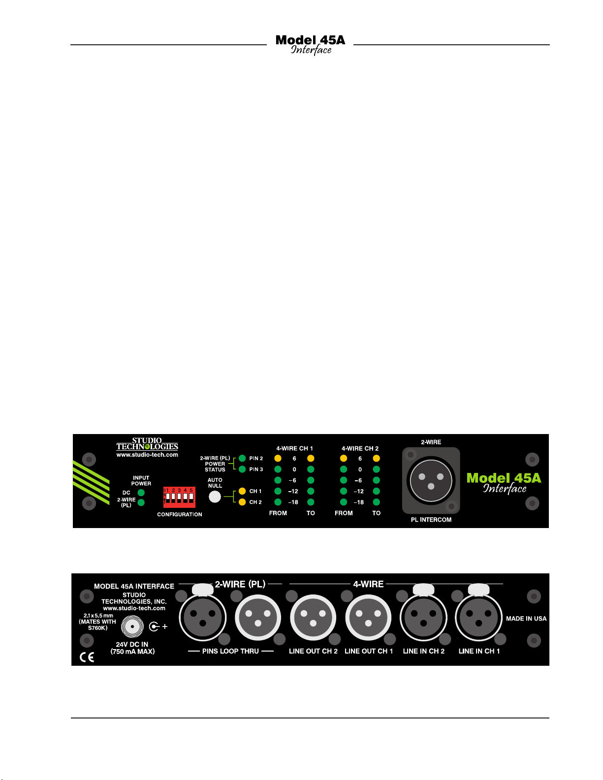
Figure 1. Model 45A with standard “throw-down” front panel
Figure 2. Model 45A back panel
Model 45A User Guide Issue 2, November 2011
Studio Technologies, Inc. Page 5

2-Wire Party-Line Interface
The Model 45A’s two-channel 2-wire partyline interface is optimized for direct connection with a dual-channel party-line intercom
circuit. In addition, single-channel partyline intercom circuits can also be connected. Many broadcast applications use the
dual-channel TW-series from RTS®, which
includes their popular BP325 belt pack.
The Model 45A’s 2-wire interface is configured for a –10 dBu nominal level, exactly
matching the level of the TW-series. Other
industry-standard single- and dual-chan
nel party-line intercom systems, including
those from Clear-Com®, are also directly
compatible. While their nominal level is
approximately 4 dB lower (–14 dBu) their
greater dynamic range tends to compensate for any operational differences.
The Model 45A’s 2-wire party-line interface
is typically connected to a powered (“wet”)
unbalanced intercom circuit. Powered
party-line circuits have a DC voltage present, typically provided by power supplies
from RTS or Clear-Com. This DC power,
normally 30-32 volts, provides energy for
connected devices such as user stations or
belt packs. A configuration setting is used
to select how the Model 45A will impact
the connected 2-wire circuit. In the default
mode the Model 45A’s circuitry maintains
a high-impedance load and draws no
power from the party-line circuit. An alternate mode allows the power required by
the Model 45A’s circuitry to be supplied by
the connected party-line circuit.
-
source mode the 30 volt, 300 milliampere
maximum output can power devices such
as user stations and belt packs. In many
applications this will eliminate the need for
an external intercom power supply. Besides
reducing total system cost, this feature can
also lower system weight, reduce required
mounting space, and decrease the mains
energy requirement.
With the 2-wire interface’s ability to supply
up to 300 milliamperes of current a typical
broadcast application which uses two or
three BP325 belt packs can easily be supported. The circuitry’s output regulation is
such that little change in the output voltage
will occur over its entire rated output current. The power source is an “industrystandard” 30 volts DC, helping to ensure
that applications requiring long intercom
cable runs will function correctly. Also,
the design of the power supply circuitry
helps to minimize the noise and “hiss”
often associated with intercom power
supplies. Under software control the DC
power supply’s output is monitored for
over-current and short-circuit conditions.
This allows protection shut-down of the
output DC, as well as providing an alert
by way of a visual indicator.
An auto terminate function ensures that
should a party-line circuit not be connected,
the Model 45A’s interface circuitry will remain stable. This unique feature makes certain that objectionable audio signals, such
as oscillations and “squeals,” will rarely be
sent to the connected 4-wire device.
A significant capability of the Model 45A’s
2-wire interface is its ability to create a
fully functioning 2-wire party-line intercom
circuit, supplying the required DC power
and 200 ohm AC terminations. Referred
to as the Model 45A’s 2-wire (PL) power
Issue 2, November 2011 Model 45A User Guide
Page 6 Studio Technologies, Inc.
Analog Hybrids with Auto
Nulling
A key reason that the Model 45A achieves
excellent audio performance is the design
of its 2-wire-to-4-wire hybrid circuits. Each

of the two independent circuits provides
low noise and distortion, good frequency
response, and high return-loss (“nulling”),
even when presented with a wide range
of 2-wire party-line conditions. Unlike telephone-line (“POTS”) oriented DSP-based
hybrid circuits, the Model 45A’s analog
circuitry provides extended frequency
response. With a pass band of 100 Hz
on the low end and 8 kHz on the high
end natural-sounding voice signals can
be sent to, and received from, the 2-wire
party-line circuit.
A hybrid’s ability to isolate the transmit
signal from the receive signal in the 2-wireto-4-wire interface is critical. The quality of
this isolation, technically known as returnloss or trans-hybrid loss, is measured in
dB. A high value is important, especially
in applications where multiple 2-wireto-4-wire interfaces are used together.
Remote sports broadcast applications
are especially sensitive to this requirement. The Model 45A’s sophisticated
auto nulling function uses analog circuitry
under microprocessor control to achieve
significant trans-hybrid loss. This returnloss “null” is achieved by making a set of
adjustments to account for the resistive,
inductive, and capacitive conditions that
are present on the connected 2-wire partyline circuit. The party-line’s conditions are
the sum of the impact made by the type
and quantity of cable, the connected user
devices, and the intercom power source.
Whenever a user presses the Model 45A’s
auto null pushbutton switch digital circuitry
adjusts the analog hybrids to achieve their
maximum return-loss. The nulling process
takes approximately 12 seconds for each
interface channel. And it’s important to
highlight that while the nulling process is
automatic, it only takes place upon user
request. The parameters obtained during
the nulling process are stored in nonvolatile memory; power interruptions won’t
require the auto nulling function to be
performed again.
The Model 45A generates a sine-wave
audio tone for use during the auto nulling
process. The signal’s frequency is software-controlled to maximize the ability
of the hybrid circuits to reach a “deep”
null. In addition, at the beginning of each
auto nulling sequence a short period of
24 kHz tone is sent to the associated
channel of the 2-wire party-line interface.
This serves as a microphone disable (“mic
kill”) signal for user devices such as the
RTS BP325. By automatically disabling
“open” microphones the auto nulling
process can achieve a better result.
4-Wire Interfaces
Associated with the 4-wire portion of
the Model 45A’s dual-channel interface
are analog line-level inputs and outputs.
These are intended to interconnect with a
variety of 4-wire devices, including matrix
intercom systems, audio-over-fiber transmission systems, and specialized audio
equipment. The input and output circuitry
is transformer-coupled to minimize the
chance of hum, noise, or ground “loop”
issues. The nominal input and output
levels are +4 dBu, helping to ensure
compatibility with professional audio
equipment. Some digital matrix intercom
systems use other nominal levels but with
their configuration flexibility they can be
easily adjusted to match the Model 45A.
For example, the Riedel Artist® system
has a nominal level of +6 dBu so an adjustment of only 2 dB is required. The RTS
ADAM™ series of matrix intercom systems has a nominal level of +8 dBu. This
Model 45A User Guide Issue 2, November 2011
Studio Technologies, Inc. Page 7

level also applies to their RVON-I/O VoIP
products. As such, reducing their nominal
input and output levels by 4 dB will ensure
optimal compatibility.
The Model 45A contains four 5-segment
LED level meters with two displaying the
level of the signals being received on the
4-wire inputs and two displaying the level
being sent out the 4-wire outputs. During
installation and setup the meters are invaluable in helping to confirm that proper
operation is taking place. The meters are
also useful during normal operation, allowing confirmation of audio signal flow into
and out of the Model 45A.
Pro Audio Quality
The Model 45A’s audio circuitry was
designed in the spirit of professional
audio equipment, rather than that found
in typical party-line intercom gear. Highperformance components are used
throughout, providing low distortion, low
noise, and high headroom. Using passive
and active filters, the frequency response
is limited to nominally 100 Hz to 8 kHz.
This range was selected to provide excellent performance for human speech, while
maximizing the ability of the hybrids to
create substantial “nulls.” When the Model
45A’s internal DC power source is selected to provide 2-wire party-line intercom
power enhanced audio performance can
also be expected. The quality of the DC
supply circuit is very good, with very little
noise, hum, or “hiss” being added to the
2-wire connection. In addition, the impedance characteristics of the interface’s DC
powered (“wet”) channel was tailored
to be essentially identical to that of the
unpowered (“dry”) channel. This unique
situation allows the automatic nulling
circuitry to provide excellent, consistent
results for both the powered and unpowered channel.
Attention to detail is a hallmark of the
Model 45A’s design. For example, during
the brief auto nulling process the interface
channel’s 4-wire input and output signals
are normally muted, preventing unwanted
audio from reaching the connected equipment. Associated with the 2-wire party-line
interface is circuitry that, under software
control, applies 200 ohm terminating
impedances to the 2-wire party-line circuit.
This, along with other circuitry that monitors DC voltages present on pins 2 and
3 of the 2-wire circuit, ensures that audio
instability associated with unterminated
circuits will rarely occur.
Special Applications
While the Model 45A is designed to directly integrate into typical applications,
it’s ready to support the “one-in-a-million”
situations too. To accomplish this five DIP
switches, accessible on the front panel,
allow control over some of the unit’s
features. For example, one DIP switch
changes the way the auto null pushbutton
switch operates. Normally pressing the
button begins the process of auto nulling
both channels. The alternate switch mode
allows each auto null sequence to be
activated independently. One “tap” of the
auto null button will begin the auto null
process for channel 1. Two “taps” of the
button will begin the auto null process
for channel 2. Another DIP switch allows
the auto terminate feature to be disabled.
While this feature can help maintain audio
quality, advanced users might need
to disable it. This would allow full control
over the Model 45A’s two hybrid circuits,
enabling them to be used in a completely
independent manner.
Issue 2, November 2011 Model 45A User Guide
Page 8 Studio Technologies, Inc.

Simple Installation
The Model 45A uses standard 3-pin XLRtype connectors, allowing convenient 2-wire
party-line and 4-wire interconnection in
broadcast and general audio environments.
For flexibility, access to the 2-wire party-line
intercom interface can be made using
either a male or female XLR connector on
the back panel or a male XLR connector
on the front panel.
In many applications the Model 45A will be
powered by an external source of 24 volts
DC. A compact, lightweight 24 volt DC output power source is supplied with each unit.
The power supply’s universal mains input
capability (100-230 volts, 50/60 Hz) allows
operation virtually anywhere in the world.
The Model 45A can also be powered by the
connected 2-wire party-line intercom circuit.
The four LED meters (previously mentioned)
make it simple to confirm operation of the
connected 4-wire inputs, 4-wire outputs,
and 2-wire party-line circuit. Additional LED
status indicators are also provided, offering
a clear view of the 2-wire DC power source,
auto null functions, and input operating
power.
The Model 45A is housed in a rugged,
lightweight aluminum enclosure that is
designed to be “road tough.” The “1/2rack” unit is ready for portable or standalone “thrown-down” applications. Three
rack-mount options are also available allowing one or two units to be mounted in one
space (1U) of a standard 19-inch rack
enclosure or one unit to be mounted in
a special 10.5-inch rack.
conventional terms, the real strength of
the unit rests in the way it integrates and
performs in the “real world.” Studio Technologies learned from conversations with
industry experts that installing and configuring 2-wire-to-4-wire interface equipment
has traditionally been a time-consuming,
aggravating process, requiring the efforts
of an expert to achieve reasonable results.
And even under those constraints the resulting audio performance was often mediocre.
This “history lesson” made it clear that any
new design had to start with a unique set
of requirements. This led to an overriding
design goal: create a “new breed of cat,”
fundamentally changing how broadcast
2-wire-to-4-wire interface equipment fits into
actual applications.
An important first step was to eliminate
the requirement that a senior technician,
along with a screwdriver, be present during every installation. (It was universally
acknowledged that their time can be better
spent elsewhere!) The need to adjust trim
potentiometers, fabricate special cabling
and connector straps, use nulling earpieces, etc. had to be eliminated. For example, in virtually all instances, input and
output levels fall within just a few dB of their
nominal values and, as such, could be supported with one industry-standard nominal
audio level. In addition, it was acknowledged that in this application analog audio
circuitry was capable of providing excellent
audio performance, but that the required
manual nulling process was operationally taxing. By adding digital control to the
analog circuitry, automatic nulling could be
performed—the best of both worlds!
Design Philosophy
While the “bits and pieces” that make up
the Model 45A have been described in
Model 45A User Guide Issue 2, November 2011
Studio Technologies, Inc. Page 9
The next step was to identify resources that
would improve the installation process and
make operation more reliable. This led to

the use of standard 3-pin XLR-type audio
connectors, enabling rapid installation and
troubleshooting in any locale. The inclusion
of LED level meters allowed continuous
monitoring of the input and output signals.
Additional status LEDs were also deemed
to be valuable. Configuration DIP switches
would allow crucial operating modes to be
selected.
A subtle but critical requirement was the
need for the Model 45A to receive its operating power from either an external 24 volt
DC source or the connected 2-wire partyline intercom circuit. It also turned out that
in many applications only a small number
of user devices, such as belt packs, were
typically connected to a 2-wire party-line
circuit. So by adding a DC power source
to the Model 45A’s 2-wire interface the
need for an external intercom power supply
could often be eliminated.
The final step was to create a physical
package that would provide significant
resources in a format that allowed simple
and reliable integration with other equipment. This was accomplished by specifying
a convenient “1/2-rack” form factor which
would be excellent for “thrown-down” use.
And by creating three “1U” rack-mount
options, it would be possible to install one
or two Model 45A units in one space of
a 19-inch rack or one unit in a special
10.5-inch rack space.
Installation
In this section you will be preparing the
Model 45A for use. Since the standard unit
is housed in a self-contained enclosure,
getting it ready for use in portable applications requires only making a few interconnections. These include 4-wire audio input,
4-wire audio output, and 2-wire party-line
intercom connections that use 3-pin XLRtype connectors. In many applications an
external source of 24 volts DC will be connected using the supplied power adapter.
For permanent installations one or two
Model 45A units can be mounted in one
of the optional rack panel adapters. The
resulting one-rack-space unit will be
mounted in either a 19-inch or a special
10.5-inch equipment rack.
Shipping Carton Contents
The shipping carton contains a Model
45A Interface, a universal input/24 volt DC
output power supply, and a user guide.
A North-American standard mains power
cord will be provided for use with the
power supply. If necessary, the dealer or
distributor will provide an AC mains cord
that is appropriate for your location. If a
rack-mount front panel is going to be used
as part of the installation it will typically be
shipped in a separate carton.
Locating the Model 45A
The location of the Model 45A will dictate
the length of the cable runs needed to link
the unit with the other required intercom
devices. This factor really only relates to
the 2-wire party-line intercom circuit.
These circuits carry unbalanced audio
which can be susceptible to interference
and crosstalk issues. And since party-line
intercom circuits typically carry DC power
a voltage drop due to resistive loss can
become an issue. In general, minimizing
the length of the 2-wire party-line intercom
cables will help to ensure more reliable
and consistent intercom system performance. The differential (“balanced”) 4-wire
circuits are typically not impacted by the
Issue 2, November 2011 Model 45A User Guide
Page 10 Studio Technologies, Inc.
 Loading...