

Page 1
User Guide
Issue 2, September 2006
This User Guide is applicable for serial numbers:
M44-00151 and later
Copyright © 2006 by Studio Technologies, Inc., all rights reserved
www.studio-tech.com
50030-0906, Issue 2
Page 2

This page intentionally left blank.
Page 3
Introduction
The Model 44 is designed to work with
200-series announcer’s console products
from Studio Technologies. The unit serves
as an interconnection “hub,” providing
power and signal routing for up to six
announcer’s consoles. The Model 44 is
appropriate for in-studio as well as field
broadcast applications. Of special note is
its applicability for use in the live television
sports industry. The compact, one-rackspace enclosure is constructed using
heavy-gauge steel components.
For installation simplicity the Model 44 connects to the announcer’s consoles using
Ethernet-type twisted-pair cable assemblies.
Each of the Model 44’s six channels connects to its associated announcer’s console
using an RJ45 jack. Of the four pairs in the
jack, two are intended for transmission of
digital audio signals. A third pair can be used
to carry digital or analog audio signals, as
well as being used for special installationspecific applications. The fourth pair is used
to carry 24 volt DC, 150 milliamperes nominal maximum, to the announcer’s console.
The power provided by each of the Model
44’s six channels is individually over-current
and short-circuit protected. This minimizes
the chance that an error on one channel will
impact the others.
A second set of six RJ45 jacks provides
access to two pairs from the announcer’s
consoles’ RJ45 jacks. These jacks are
normally used to connect the digital audio
input and output signals to the main broadcast system equipment, such as a digital
matrix intercom system, an audio console,
or a routing switcher. The Model 44 also
provides a 25-pin D-subminiature connector that is used to provide access to a third
cable pair from the announcer’s consoles’
RJ45 jacks.
The unit’s mains power input can be in the
range of 100 to 230 volts, 50/60 hertz. This
“universal input” ensures correct operation
virtually anywhere in the world. Two 24 volt
nominal, 30 watt internal power supplies
provide redundancy for critical broadcast
applications. For special applications an
external source of 24 volts DC can also be
connected. This allows, for example, battery
operation of the Model 44 and associated
announcer’s consoles. Three LED indicators, located on the unit’s front panel, provide status indication of the two internal and
one external power sources.
For special applications the Model 44
provides a nominal 24 volt, 70 milliamperes
nominal maximum power source. This
source could be useful when connecting
devices such as “tally” status indicators.
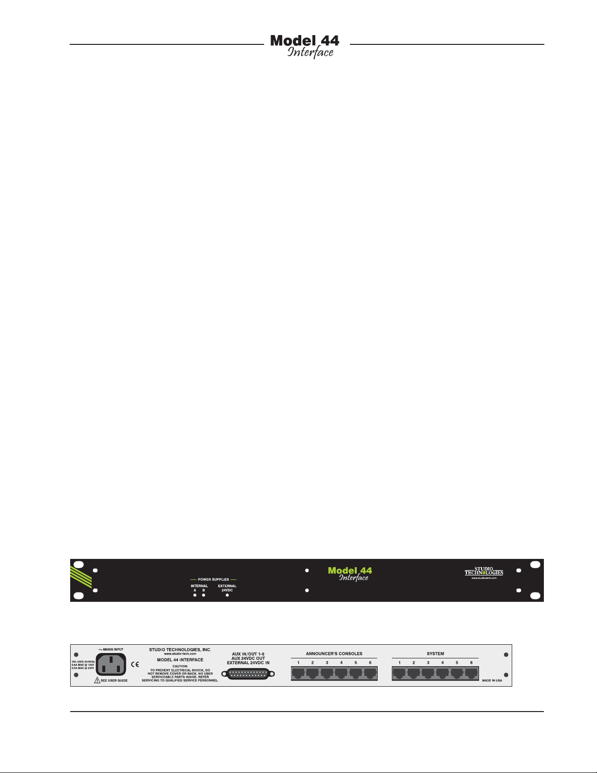
Model 44 Front Panel
Model 44 Back Panel
Model 44 User Guide Issue 2, September 2006
Studio Technologies, Inc. Page 3
Page 4

Typical Application
A typical application would be to use the
Model 44 Interface with up to six of the
Model 212 Announcer’s Consoles. The
Model 212 features digital audio inputs and
outputs with support for both AES3id (75
ohm unbalanced) and AES3 (110 ohm balanced) signals. To provide RJ45 interfacing
capability, an EtherCon® interface connector kit, available from Studio Technologies,
would be installed in one of the spare connector locations on the back of the Model
212. Using jumper wire assemblies three of
the four cable pairs are assigned to Model
212 functions. One pair carries nominal 24
volt DC power from the Model 44 to the
Model 212’s circuitry. Two other pairs are
used to carry AES3 (110 ohm balanced) digital audio signals to and from the Model 212.
The fourth pair can remain unused, or be
used to implement a special function such
as a remote microphone on/off switch.
Installing and wiring the Model 44 in our
typical application is very simple. Standard
unshielded twisted-pair cable assemblies,
ubiquitous to the computer industry, can
be used to connect the Model 212 units
to the RJ45 jacks on the back panel of the
Model 44. Alternately, ruggedized cable
assemblies can be fabricated using Neutrik®
EtherCon connectors. A second set of six
RJ45 jacks, also located on the Model 44’s
back panel, are used to link the digital audio
input and output signals with other equipment. For example, to interface with the
Riedel® Artist® intercom system would
require only the use of standard Ethernettype 4-pair cable assemblies. If the fourth
pair of the interconnecting cables has been
implemented with a Model 212 function,
its signals are accessible using the 25-pin
D-subminiature connector. The “D-sub”
connector, located on the Model 44’s back
panel, is also used for connecting to the
auxiliary 24 volt DC output and the external
24 volt DC input. To complete the installation typically requires only the power cord
to be connected to the designated source
of AC mains power.
Installation
In this section you will be installing and
interconnecting the Model 44. The onerack-space unit will be mounted in an
equipment rack. Connections to the announcer console units and associated
equipment will be made using twelve RJ45
jacks. Installer-selected input, output, or
control signals can be connected using
pins on the female 25-pin D-subminiature
connector. An external source of 24 volts
DC power can also be connected using
pins on the female 25-pin D-subminiature
connector. The same female 25-pin “D-sub”
is also used to access the auxiliary 24 volt
DC output. AC mains power is connected
by means of a detachable cord set that is
compatible with the Model 44’s 3-pin IEC
320 C14-type inlet connector.
System Components
The shipping carton contains the Model 44
Interface and associated user guide. Units
destined for North America and Japan also
include an AC mains cord. Your dealer or
distributor should provide an AC mains
cord for other destinations.
Locating the Model 44
In most cases the 100 meter cable length
limit for AES3 digital audio signals will
dictate the Model 44’s mounting location.
One cable will link the Model 44 to the
announcer’s console units. A second cable
will connect the Model 44 to the associated
digital audio equipment. Ensure that the
Issue 2, September 2006 Model 44 User Guide
Page 4 Studio Technologies, Inc.
Page 5

total length of the two cable segments
doesn’t exceed 100 meters.
Mounting the Model 44
Once the desired mounting location has
been selected, the Model 44 will require one
space (1.75 vertical inches) in a standard
19-inch equipment rack. Secure the unit
into the equipment rack using two mounting
screws per side.
Announcer’s Console
Connections
The Model 44 provides support for up to six
announcer’s consoles. In most cases these
will be digital audio-compatible units such
as the Model 212 from Studio Technologies.
On the Model 44’s back panel are six RJ45
(8-position modular) jacks, one for each
announcer’s console connection. The eight
signal connections in the RJ45 jacks are
organized as four pairs and use the Ethernet convention: pins 4 and 5 (pair 1), pins 1
and 2 (pair 2), pins 3 and 6 (pair 3), and pins
7 and 8 (pair 4). Pair 4 is used to provide
power to the announcer’s console: +24 volts
DC on pin 7, common on pin 8. Pair 2 (pins
1 and 2) is intended to carry digital audio
signals from the announcer’s console to the
connected equipment. Pair 3 (pins 3 and 6)
is intended to carry digital audio signals from
the connected equipment to the announcer’s
console.
Inside the Model 44 pairs 2 and 3 are routed
directly to six additional RJ45 jacks. Pair 1
(pins 4 and 5) is intended for use in installerselected applications. These include sending
or receiving analog audio, digital audio, control, or “tally” signals. The connections from
pair 1 (pins 4 and 5) on all six announcer’s
console RJ45 jacks are connected inside
the Model 44 to pins on the female 25-pin
D-subminiature connector.
Figure 1. RJ45 Jack (8-Position Modular)
Figure 2. RJ45 Plug (8-Position Modular)
In fixed installations standard CAT5 or
CAT5e Ethernet-style 4-pair cabling can
be used to link the Model 44 with the
announcer’s consoles. The cables should
be implemented with a straight-through
“568A” or “568B” wiring scheme. For remote broadcast or sound reinforcement
applications it may be desirable to use
ruggedized “tactical” cables. In this case
using protected RJ45 plugs, such as the
Neutrik EtherCon, may be appropriate. An
input/output (I/O) panel, separate from the
jacks on the Model 44, should be created
Model 44 User Guide Issue 2, September 2006
Studio Technologies, Inc. Page 5
Page 6

as the interconnection point. Short “jumper”
cables can be used to link the RJ45 jacks
on the Model 44 with the connectors on
the I/O panel. Using feed-through adapters (standard RJ45 to ruggedized RJ45) on
the I/O panel, such as the Neutrik NE8FDP,
make this type of installation simple.
System Connections
Inside the Model 44, pairs 2 and 3 (pins 1
and 2, 3 and 6) on the RJ45 jacks associated with the announcer’s consoles are connected directly to six addition RJ45 jacks.
These jacks, located on the Model 44’s
back panel, maintain a one-to-one connection scheme: pin 1 to pin 1, pin 2 to pin 2,
pin 3 to pin 3, pin 6 to pin 6. These six RJ45
jacks, labeled System, are intended to connect to the audio equipment that will send
and receive digital audio signals associated
with the announcer’s consoles.
The required system interconnecting cables
will depend on the type of equipment to be
interfaced. In some cases standard Ethernet
CAT5 or CAT5e “patch” cables may be all
that is required. An example would be ports
on a digital matrix intercom system from
Riedel Communications. In other cases
adapters going from RJ45 to 3-pin XLR-type
may be appropriate.
Auxiliary Input/Output Connections
As previously mentioned, connections
from pair 1 (pins 4 and 5) of the RJ45 jacks
associated with the announcer’s consoles
are directly connected to pins on a female
25-pin D-subminiature connector. This
connector, located on the Model 44’s back
panel, is provided for installer-selected applications. A cable harness is required with
a male 25-pin D-sub plug on one end and
the desired mating connectors on the other.
This cable harness is not supplied by Studio
Technologies. (Note that in some locations
the term “cable loom” may be used instead
of “cable harness.”) Some of you might
observe that the wiring scheme used by the
D-sub complies with the now-ubiquitous
one made familiar by TASCAM® with their
DA-88® product. A wiring harness prepared
for connection to the Model 44’s audio
inputs is identical to a DA-88-style input harness. Please refer to Figure 3 for connection details. Note that unlike a DA-88-style
harness, the Model 44’s D-sub connector’s
hold-down screws use 4-40 threads. This
complies with the original design standard
for D-subminiature connectors which used
English rather than metric thread pitch.
RJ45 RJ45
Connections Pin 4 Pin 5 Shield
To/From Announcer’s Console 1 24 12 25
To/From Announcer’s Console 2 10 23 11
To/From Announcer’s Console 3 21 9 22
To/From Announcer’s Console 4 7 20 8
To/From Announcer’s Console 5 18 6 19
To/From Announcer’s Console 6 4 17 5
Notes: 1) Connector type on Model 44 is 25-pin
D-subminiature female. Installer must provide plug
(male). Connector uses 4-40 threaded inserts for
locking with mating plug.
2) Wiring scheme follows TASCAM DA-88 convention.
Standard DA-88-style wiring harnesses are directly
compatible, with the exception of 4-40 screw threads
being required.
Figure 3. Connections for Auxiliary Input/Outputs
Auxiliary DC Output
A source of 24 volts DC, 70 milliamperes
nominal maximum, is provided for installerselected applications. It may prove useful
in specialized installations such as where
broadcast remote control and tally signals
are required. The DC output is accessible
by way of pins on the female 25-pin
Issue 2, September 2006 Model 44 User Guide
Page 6 Studio Technologies, Inc.
Page 7

D-subminiature connection, located on the
Model 44’s back panel. Refer to Figure 4 for
connection details.
External DC Input
For flexibility, provision has been made
to allow an external source of 24 volts DC
to power the Model 44. The source must
be filtered and regulated, with a minimum
current capability of 1.2 amperes. The external DC source is connected using two pins
on the female 25-pin D-subminiature connector which is located on the Model 44’s
back panel. For connection details refer
to Figure 4.
The external 24 volt DC source can be used
instead of, or in addition to, the DC power
created by the two internal power supplies.
These three possible power sources are
safely connected together (diode “OR’d”)
within the Model 44’s circuitry.
match a location’s nominal AC mains voltage. For locations that have an AC mains
power source of 240 volts, contact Studio
Technologies for confirmation that a direct
connection can be made.
The Model 44 uses a 3-pin IEC 320 C14type inlet connector to mate with a detachable mains cord set. For units shipped to
North America and Japan a cord is supplied that has a North-American (NEMA
15L) standard plug on one end and an IEC
320 C13-type connector on the other. Units
bound for other destinations require that
the appropriate cord set be obtained. The
wire colors in the mains cord must conform
to the internationally recognized color code
and should be terminated accordingly:
Connection Wire Color
Neutral (N) Light Blue
Line (L) Brown
Earth/Ground (E) Green/Yellow
No
Connections + – Connect
Aux 24 Vdc Output 15 3 16
External 24 Vdc Input 1 14 2
Notes: 1) Connector type on Model 44 is 25-pin
D-subminiature female. Installer must provide plug
(male). Connector uses 4-40 threaded inserts for
locking with mating plug.
2) Wiring scheme follows TASCAM DA-88 convention.
Standard DA-88-style wiring harnesses are directly
compatible, with the exception of 4-40 screw threads
being required.
Figure 4. Connections for Auxiliary 24 Volt DC
Output and External 24 Volt DC Input
AC Mains Power
The Model 44’s two internal power supplies
operate directly from AC mains power of
100 to 230 volts, 50/60 hertz. The power
supplies are “universal input” type with
no switches to set or jumpers to install to
Safety Warning: The Model 44 does not
contain an AC mains disconnect switch.
As such, the AC mains cord plug serves
as the disconnection device. Safety
considerations require that the plug and
associated inlet be easily accessible to
allow rapid disconnection of AC mains
power should it prove necessary.
As soon as AC mains power is applied the
Model 44 will begin operation. An LED status indicator is associated with each of the
two internal power supplies. Both should
light as soon as mains power is applied.
Operation
The Model 44 is designed for continuous
operation with no adjustment or maintenance required. Three red-colored LEDs,
Model 44 User Guide Issue 2, September 2006
Studio Technologies, Inc. Page 7
Page 8

visible from the front panel, provide a status
indication of the active power source(s).
Two of the LEDs light whenever their respective internal power supplies are functioning. With AC mains power connected
both should be lit. If an external source of
24 volts DC is connected it’s LED should
also be lit.
be checked. Straight-through wiring is required. The connection is polarity sensitive,
with positive on pin 7 and common on pin 8.
Specifications
Applications: designed to work with up to six
Model 200-series announcer’s consoles from
Studio Technologies
Troubleshooting
If you’re having trouble getting the Model 44
up and running, this section may help.
If you haven’t read the previous sections
of this guide, you should do so before
proceeding.
The first thing to confirm, no matter what
symptoms are present, is that the desired
source of incoming power has been correctly connected. If a source of AC mains
power is being provided to the Model 44,
the two LEDs associated with the internal
power supplies should be lit. If neither is lit
check the AC mains source to ensure that it
is active and that the power cord is securely
mated with the power entry connector. If
only one of these LEDs is lit, a defective
power supply is most likely the cause. While
temporary operation with one only functioning internal power supply is acceptable,
long-term reliability will be compromised. In
this case the Model 44 needs to be returned
to the factory for repair. If an external source
of 24 volts DC has been connected, its associated LED indicator, located on the front
panel, should be lit. If it is not, check the
power source and associated wiring.
Correct operation of the connected announcer’s consoles is primarily dependent
on accurate interconnect wiring. If the
announcer’s consoles do not “power up”
then the wiring associated with pair 4 (pins
7 and 8) of the interconnecting cable must
Announcer’s Console Power Sources: 6
24 volts DC nominal (26 volts actual with internal
power supplies active), 150 milliamperes nominal
maximum; over-current and short-circuit protected
Interconnection Cable Limit: designed to correctly
support 200-series announcer’s consoles located up
to 100 meters from Model 44 when using standard
computer-type unshielded twisted-pair cabling
Auxiliary 24 Volt DC Output: 24 volts DC nominal
(26 volts actual with internal power supplies active),
70 milliamperes nominal maximum; over-current and
short circuit protected
External 24 Volt DC Input: 24 volts nominal
(24-28 volts acceptable), 1.2 amperes minimum
Connectors:
Announcer’s Console: 6, RJ45 (8-position
modular)
System: 6, RJ45 (8-position modular)
Aux In/Out, Aux 24 Volt DC Output, External 24 Volt
DC Input: female 25-pin D-subminiature, 4-40 threads
AC Mains: 3-blade, IEC 320 C14-compatible (mates
with IEC 320 C13)
AC Mains Requirement: 100-230 volts, 50/60 Hz,
0.8 A maximum @ 100 volts, 0.5 A maximum
@ 230 volts
Dimensions (Overall):
19.00 inches wide (48.3 cm)
1.72 inches high (4.4 cm)
9.58 inches deep (24.3 cm)
Mounting: one space in a standard 19-inch rack
Weight: 6.3 pounds (2.9 kg)
Specifications and information contained in this User
Guide subject to change without notice.
Issue 2, September 2006 Model 44 User Guide
Page 8 Studio Technologies, Inc.
Page 9

 Loading...