

Page 1
User Guide
Issue 1, July 2004
This User Guide is applicable for serial numbers:
M43-00151 and later
Copyright © 2004 by Studio Technologies, Inc., all rights reserved
www.studio-tech.com
50020-0704, Issue 1
Page 2

Table of Contents
Introduction ................................................................... 5
Setup ............................................................................. 7
Operation ...................................................................... 10
Troubleshooting ............................................................ 10
Technical Notes ............................................................. 12
Specifications ................................................................ 14
Appendix A .................................................................... 16
Block Diagram
Model 43 User Guide Issue 1, July 2004
Studio Technologies, Inc. Page 3
Page 3

This page intentionally left blank.
Issue 1, July 2004 Model 43 User Guide
Page 4 Studio Technologies, Inc.
Page 4
Introduction
The Model 43 is designed to create a
broadcast-standard IFB circuit from two
line-level audio sources. The unit will find
use in on-air and production broadcast
applications, as well as specialized applications such as post-production, recording
studio, and equipment test and maintenance. The Model 43 is a unique and versatile product, providing the resources to
easily create a high-performance “wet” IFB
circuit in a compact, easy-to-use package.
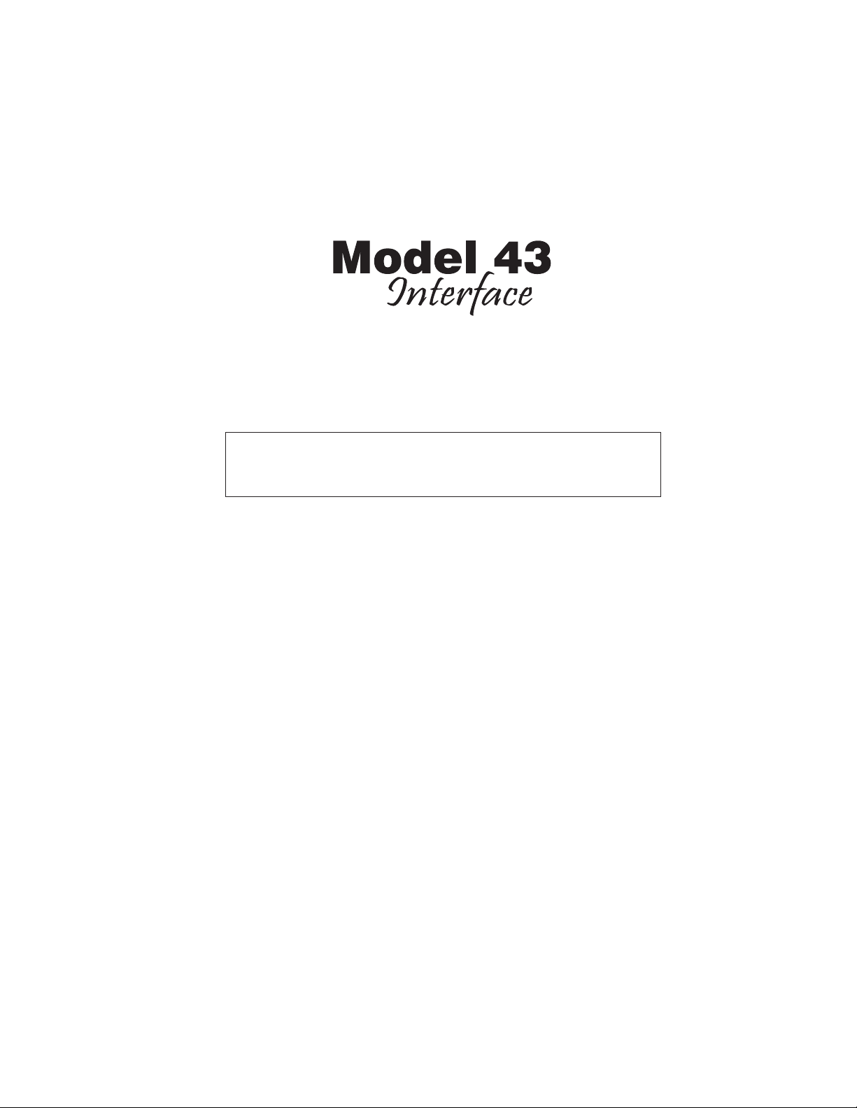
The Model 43’s audio inputs are compatible
with standard line-level audio sources, including analog outputs associated with digital matrix intercom systems. The unit’s IFB
circuit provides DC power and two analog
audio signals to support a range of IFB user
devices. The audio quality is excellent—little
hiss, hum, or other artifacts are present. The
Model 43 is housed in a rugged aluminum
enclosure, making it suitable for permanent
or temporary applications. All inputs and
outputs interface using industry-standard
3-pin male and female XLR-type connectors. The connectors are manufactured by
Neutrik® and feature gold-paled contacts
and metal housings. A source of 24 volts
DC is required for operation. Included with
each unit is an external wall-mount 24 volt
DC power source.
View showing left and right audio inputs
There may be persons not familiar with
the term IFB. That’s not unreasonable as
it’s a somewhat obscure acronym for interrupted foldback. (It can also be known
as interruptible foldback.) On its own, the
term “foldback” is an alternate way of describing a cue or monitor function. Adding
“interrupted” before it means that the cue
source can be temporarily replaced with
an audio signal originating from a producer, director, or other production personnel. IFB circuits are often used in the
broadcast industry for talent cueing applications, in both studio and field settings.
Both “dry” and “wet” IFB circuits can be
deployed and their characteristics are
worth reviewing. The term “dry” IFB typically refers to a transformer-balanced linelevel audio circuit with a +4 dBu nominal
level. This is essentially a standard audio
circuit that is commonly used to interconnect audio equipment. The term “wet” IFB
refers to a circuit that combines DC power
and one or two channels of analog audio.
The audio is unbalanced with a typical
nominal level of –10 dBu. A wet IFB circuit
is the type implemented by the Model 43.
As such, in this user guide the term IFB
will always indicate a wet circuit.
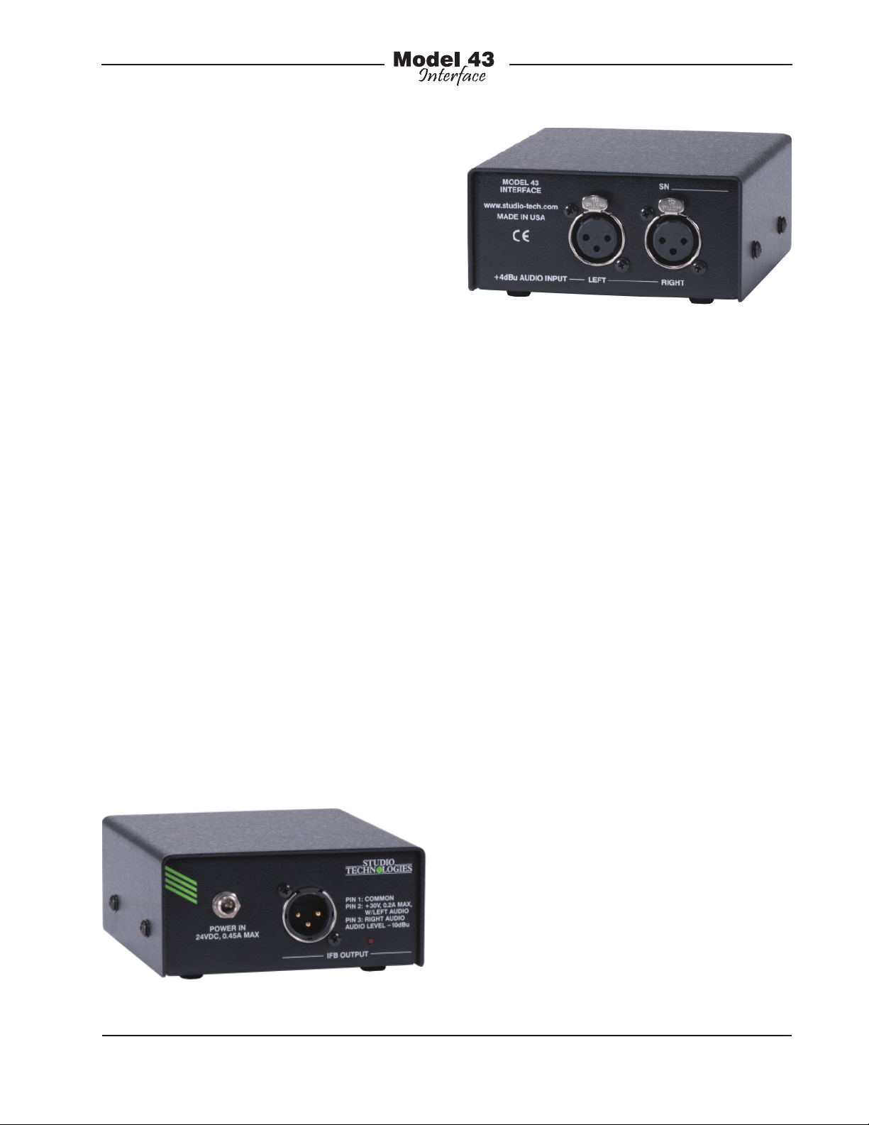
IFB circuits provide an effective means
View showing 24 volt DC input and IFB circuit
connections
Model 43 User Guide Issue 1, July 2004
Studio Technologies, Inc. Page 5
of delivering power and two channels
Page 5

of audio to user devices by means of standard audio cables. These cables, ubiquitous to the audio industry, interface using
3-pin male and female XLR-type connectors. With IFB circuits and standard audio
cables it’s a simple matter to support user
devices such as listen-only belt packs and
announcer’s consoles with no external
power source required. Whether the distance from the source to the user device is
100 or 1000 feet, reliable operation can be
provided.
In many cases, the Model 43 Interface will
be used in on-air television applications.
No matter if a unit is installed in a fixed
location or as part of a remote facility,
excellent performance can be obtained.
In addition, the Model 43 is applicable for
non-broadcast applications. For example,
audio recording and post-production
facilities can also effectively use the unit.
Combined with stereo or mono listenonly belt packs, also available from Studio
Technologies, a variety of headphone
cue systems can easily be deployed.
Maintenance facilities and test benches
will appreciate having a Model 43 available to provide assistance during the
testing and repair of IFB user devices. As
the unit’s audio inputs are compatible with
standard line-level audio signals virtually
any analog source can be connected.
from matrix intercom systems. If this is the
case, two sources are typically designated
to feed user cue signals to stereo or monaural headsets or headphones. Generally
one source is configured in the matrix
intercom system as “interrupt” while the
other is configured as “program.” An alternate term often used for the “interrupt”
channel is “program-with-interrupt.” This
may be more descriptive as the function
is actually a program source that gets
interrupted with talkback audio. The “program” channel is typically a continuous
source of program audio. An alternate
term is “program-only.” For other applications the Model 43’s audio inputs can
be connected to one or two monaural
sources, or alternately, to a stereo audio
source. This configuration may prove useful in radio broadcasting, audio-with-picture, or recording studio applications.
Maintaining excellent audio performance
was a major Model 43 design goal—the
hiss, hum, and noise associated with
typical IFB circuits was simply not acceptable. The Model 43 meets those requirements with audio that is “on-air” quality:
low distortion, high signal-to-noise ratio,
and ample headroom. On-air talent and
guests, production personnel, and technicians will all appreciate the clean, quiet
cue signal.
IFB Circuit
The Model 43 supplies one circuit that
incorporates two audio inputs and a
“wet” IFB output. The audio inputs are
transformer coupled, have a nominal
level of +4 dBu, and are compatible with
balanced or unbalanced sources. In onair television broadcast applications the
audio sources will often be analog outputs
43’s IFB circuit provides DC power and
two channels of unbalanced audio over
a single 3-conductor output. The DC output is nominally 30 volts with a maximum
rated current of 200 milliamperes. A major
strength of the Model 43 is the IFB circuit’s
ability to effectively deliver DC power over
a variety of conditions. Unlike other interface devices that use a common but lessthan-ideal circuit topology, a unique IFB
Issue 1, July 2004 Model 43 User Guide
Page 6 Studio Technologies, Inc.
As previously covered briefly, the Model
Page 6

circuit was developed by Studio Technologies to achieve the desired performance
goals. The result is a major improvement
in effectively supporting IFB user devices
over a wide range of conditions. Connected devices can draw up to the full
rated 200 milliamperes of current with little
drop in DC voltage. This output voltage
stability is the key—whether drawing 50,
100, or 200 milliamperes, the output will
remain close to 30 volts. In practical terms
this means that reliable IFB-based cue
systems can now be deployed in more
stadiums, concert halls, or motor racing
facilities than was previously possible.
Compatibility
The Model 43’s audio inputs are compatible with virtually every digital matrix
intercom system, including those from
Clear-Com®, Drake, RTS™, and Riedel
Communications. Interfacing requires
only the connection of analog output ports
from the intercom system to the Model
43’s audio inputs. The Model 43’s IFB
circuit allows virtually any IFB user device
to be supported. These include the Model
30-series listen-only belt packs and Model
200-series announcer console products
from Studio Technologies. The announcer
console units combine a variety of microphone control, headphone monitoring,
IFB and intercom system interfacing, and
related functions into compact desktop
units. Industry-standard listen-only belt
packs from RTS, including the 4020 and
4030, can also be directly supported.
Alternate Applications
In addition to broadcast IFB applications,
the Model 43 can be used to create a
high-performance stereo headphone cue
system. Line-level signals coming from
audio consoles, routing switchers, or off-air
receivers can be connected to the Model
43’s audio inputs. The IFB circuits can be
connected to listen-only belt packs, several
models of which are available from Studio
Technologies. For example, the Model 35
Talent Amplifier will allow one or two pairs
of stereo headphones to be supported. The
Model 43’s IFB circuit will support up to six
Model 35 Talent Amplifiers.
Setup
In this section you will be unpacking and
reviewing the Model 43. For permanent
applications a specific location will be
selected. Audio input and IFB circuit output
connections will be made by way of 3-pin
XLR-type connectors. A 24 volt DC power
source will be connected by way of the
2.1 x 5.0 mm coaxial input power jack.
System Components
The shipping carton contains the Model
43 Interface, 24 volt DC power supply, and
associated user guide. For units shipped
to destinations in North America and Japan
the power supply will have a nominal AC
mains input of 120 volts. For other destinations a power supply compatible with
220/240 volts will be included.
Locating the Model 43
The location selected for the Model 43
depends on how the unit is going to be
used. In a permanent application the unit
can be placed on a shelf that’s available
in an equipment room or rack cabinet.
For portable applications the unit can be
placed on most any table or available
surface. (The reality might be that the unit
is simply “tossed” in a convenient location
Model 43 User Guide Issue 1, July 2004
Studio Technologies, Inc. Page 7
Page 7

inside the maze of wires, equipment, and
road cases associated with field production!) The unit generates essentially no
heat so providing special ventilation isn’t
an issue; any environment where the longterm ambient temperature is less than 80
degrees Fahrenheit is adequate. When
selecting a location keep in mind that an
outlet must be available to allow the 24
volt DC power source to be plugged in.
As one would expect, the specific location
selected for the Model 43 will dictate the
length of cable that will be needed to link
the unit with the connected device(s). In
some cases the location choice will have
already been established. For example,
in field broadcast applications the Model
43 will almost always be located in a
production truck or trailer. But in fixed applications it may be possible to select the
mounting location so as to minimize cable
length. In general, a shorter cable run will
lead to a more reliable and better performing system.
Audio Input Connections
For simplicity, the Model 43’s two linelevel audio inputs are designated as left
and right. In many broadcast settings
the left input would correspond to channel 1 and the right channel to channel 2.
For on-air television applications the IFB
sources are generally configured to provide a single- or dual-channel cue “feed”
to talent personnel. In such cases the left
channel is generally designated as the
“interrupt” channel while the right channel
is the “program” channel. For other broadcast applications, such as live radio, it’s
possible that a stereo cue source will be
connected. In this situation the left source
would connect to the left input while the
right would connect to the right input. This
might also be the case with other professional audio applications, such as recording and post-production.
Audio input connections are made by
way of two 3-pin female XLR-type connectors which are located on one side of
the Model 43’s enclosure. The audio input
circuits are transformed coupled with a
nominal impedance of 10 K ohms. They
have a nominal signal level of +4 dBu
and are compatible with balanced or unbalanced sources. With balanced sources
the mating connectors (males) should be
wired so that signal high (+ or hot) is connected to pin 2, signal low (– or cold) to
the pin 3, and shield to pin 1. With unbalanced sources, connect signal high to
pin 2, and shield to both pins 1 and 3. If
connecting an unbalanced source in this
manner results in hum or noise, try connecting signal high to pin 2, and shield to
pin 3; leave pin 1 unterminated.
As previously mentioned, the Model 43 is
compatible with matrix intercom systems
from Riedel Communications. Appendix
A, located near the end of this user guide,
provides detailed connection information.
Audio Input Source Level
Adjustment
Literally any audio source with a nominal
operating level of +4 dBu can be successfully connected to the Model 43’s audio inputs. Transformer coupled, the inputs are
compatible with balanced or unbalanced
signals. In some applications two analog
outputs from a digital matrix intercom
system will be connected to the Model 43.
It’s important to confirm and, if required,
adjust the nominal output level provided
by the specific system. In reality, it’s acceptable that the nominal level deviates
Issue 1, July 2004 Model 43 User Guide
Page 8 Studio Technologies, Inc.
Page 8

slightly from precisely +4 dBu. But with
the power of contemporary computer-controlled intercom systems there’s no reason why sources with precisely calibrated
levels can’t be easily supplied.
From our research we found that the
Clear-Com Eclipse™ system specifies a
nominal level of 0 dBu. Since their headroom is listed as greater than 18 dB,
increasing the nominal level of their analog output ports by 4 dB (to achieve the
desired +4 dBu) should be acceptable.
RTS in their ADAM™ and ZEUS™ systems
specify nominal output levels of +8 dBu.
With these systems maximum Model 43
performance would be provided by reducing their nominal output levels by 4 dB.
With the Artist™ system from Riedel,
the analog ports have a nominal level
of +6 dBu. A 2 dB reduction in their output level would be beneficial.
IFB Circuit
As mentioned previously, the Model 43
supplies one IFB circuit that provides DC
power and two channels of unbalanced
audio. The IFB circuit is designed to
connect to a variety of user devices that
conform to the broadcast IFB standard.
In this implementation pin 1 is used for
a combination of shield, DC power return, and audio common; pin 2 supplies a
combination of DC power and one channel of unbalanced audio; pin 3 supplies
a second channel of unbalanced audio.
With the Model 43, the DC power supplied
on pin 2 is 30 volts nominal with a maximum rated current of 200 milliamperes.
The audio superimposed on the DC power
comes from the left audio input and has a
nominal signal level of –10 dBu. The audio
on pin 3 has a nominal level of –10 dBu.
Its source is the right audio input.
The Model 43’s IFB circuit is interfaced
using a 3-pin male XLR-type connector
which is located on one side of the unit’s
enclosure. The associated interface cable
must be terminated with 3-pin female XLRtype connector. In permanent applications
it’s a good idea for the IFB circuit to be
wired by way of an input/output connector panel rather than directly to the user
device(s). It’s also recommended that the
panel have “mults” (multiple connectors)
for the IFB circuit. For troubleshooting
purposes it also may be useful to have
the IFB circuit pass through points on an
audio patch bay.
The type of interconnecting cable used
between the Model 43’s IFB circuit and
the user device(s) will vary by application.
In a fixed installation it would be typical
to use 22AWG shielded cable in either a
single- or 2-pair configuration. With singlepair cable, pin 1 of the “XLR” should be
connected to the shield and pins 2 and 3
connected to the cable pair. If 2-pair cable
is used, pin 1 should be connected to one
side of each pair, with pin 2 going to one
side of the first pair and pin 3 going to one
side of second pair. The shields can either
go only to the XLR connector shell or to
both the connector shell and pin 1.
As any audio person “worth his salt”
knows, effectively shielding unbalanced
audio signals can be a tricky proposition.
It is recommended that the focus be on
using excellent twisted-pair cable, rather
than worrying about whether or not it is
shielded. The typical foil shield used in
most contemporary audio cable generally
offers very limited effectiveness. The best
rule to follow is to always try to minimize
exposure to large noise sources. (Okay,
so that’s hardly ever practical but at least
it’s a nice dream!)
Model 43 User Guide Issue 1, July 2004
Studio Technologies, Inc. Page 9
Page 9

In the event that a very long cable run is
required, the resistance of the cable can
impact the DC power supplied by the
Model 43. There’s no way to get around the
fact that some DC voltage will be dropped
by the interconnecting cable. A simple
ohms law calculation will tell you the impact
a specific cable run will have. You’ll need
to know the current draw of the connected
device(s), the minimum voltage required by
the connected device(s), and the resistance
of the cable’s conductors. This is generally
stated as ohms per 1000 feet. Make sure
that you account for the resistance in both
the pin 1 and pin 2 legs! In general, if there
is the potential for a cable-length problem,
moving to a more substantial cable gauge,
such as 20, 18, or 16 can be effective.
24 Volt DC Power
An external source of 24 volts DC nominal
is required for Model 43 operation. (In reality, correct operation will take place with
any source that is in the range of 20 to 32
volts.) The unit requires 450 milliamperes
(0.45 amperes) maximum for correct operation. The power source is connected by
way of a 2.1 x 5.0 mm coaxial power jack
that is located on one side of the Model
43’s enclosure, adjacent to IFB circuit’s
connector. The center pin of the jack is
the positive (+) connection.
A 24 volt DC external power supply is
included with each Model 43. The power
supply’s DC output cable is terminated
with a compatible but non-locking power
plug. For special applications, a provision
has been made to support a positive “lock”
between the external source and the Model
43’s jack. An installer can terminate the
cable associated with the external source
using a Switchcraft® S760K “locking” plug.
Using its threaded bushing, this plug can
be secured onto the Model 43 power entry
jack. As soon as 24 volts DC is applied,
the Model 43’s power present LED will
light. The unit is now fully functional.
Operation
There are no switches, potentiometers,
or user controls associated with the Model
43. It’s designed for continuous operation
with no adjustment or maintenance required. Proper operation will take place
as long as attention is paid to the level
presented on the audio inputs and the
loading placed on the IFB circuit.
Troubleshooting
If you’re having trouble getting the Model
43 up and running, this section may help.
If you haven’t read the previous sections
of this guide, you should do so before
proceeding.
If the Model 43 Doesn’t Work
At All
A source of nominal 24 volt DC power
must be connected to the Model 43. The
unit is fairly forgiving of the power that is
applied; generally anything between 20
and 32 volts DC is acceptable. Whenever
power is connected the power present
LED should be lit. This LED is powered by
the 30 volts DC that is provided on pin 2
of the IFB circuit output connector. If the
LED is not lit confirm that external 24 volt
DC power source is active and that its
connector is securely mated with the inlet
connector. Also ensure that an acceptable
load is being place on the IFB circuit.
Issue 1, July 2004 Model 43 User Guide
Page 10 Studio Technologies, Inc.
Page 10

In all foreseeable situations, both normal and abnormal, the LED should be lit.
However, it’s possible that if the IFB circuit
is presented with an over current or short
circuit condition the circuitry may enter
its protection mode and shut down. In
this case the LED will not light, or will light
intermittently. If the LED presents this
scenario, even after confirming that 24
volts DC is correctly being applied, try
removing the load from the IFB circuit.
The easiest way to do this is to remove
the 3-pin female XLR-type connector that
is plugged into the Model 43. If after a few
seconds the LED again lights, carefully
check the IFB circuit wiring for a fault
condition.
The easiest means of confirming that the
Model 43 is being presented with the
correct audio levels is to use a Model 72
Level Meter/Interface, also available from
Studio Technologies. The Model 72 is
a compact, portable device that plugs
directly into an IFB or intercom circuit
and provides two useful functions. Two
5-segment LED meters display the audio levels present on pins 2 and 3 of the
circuit. In addition, two “dry” line-level
audio outputs are provided. The Model 72
should prove to be very useful, both during initial Model 43 installation and routine
system testing. Complete information on
the Model 72 is available on the Studio
Technologies website.
If the LED still doesn’t light, even after confirming that an external source of 24 volts
DC is present and that the IFB circuit
is not shorted, it’s likely that the unit
requires factory service. The Model 43
must be returned to the factory, or an
authorized service location, for review
and repair.
Maintaining Correct Input
Signal Levels
The Model 43’s two audio inputs are designed for nominal signal levels of
+4 dBu. Applying signal levels significantly lower than +4 dBu will reduce the
signal-to-noise ratio (raising the perceived
noise floor) and can prevent the connected user devices from operating optimally.
Applying signal levels significantly higher
than +4 dBu will reduce the headroom
and greatly increase the chance of reaching audio “clipping.” Obviously, these cautions are not unique to the Model 43, but
apply to most audio equipment.
Maintaining Correct IFB
Circuit Current Draw
The Model 43’s IFB circuit is designed
to provide up to 200 milliamperes of DC
current. By design, the circuit is protected
so that an overload condition, or even a
complete short circuit, should not cause
damage. Exceeding about 220 milliamperes will cause the protection circuitry to
come into play. An overload condition will
cause the output voltage to shut off continually or intermittently. The exact action
will depend on the specific overload condition that is present. In general, the more
extreme the overload condition, the sooner normal operation will cease. Restoring
the output load to be within the rated 200
milliamperes will allow the output to again
operate normally. A few seconds may be
required from the time an overload condition is removed and when normal operation again takes place. Please don’t test
the Model 43’s ability to sustain frequent
overload or short-circuit conditions! The
Model 43 User Guide Issue 1, July 2004
Studio Technologies, Inc. Page 11
Page 11

long-term reliability of the unit can be impacted by the stress caused by these fault
conditions.
If there is concern that an excessive load
is being placed on the IFB circuit, performing a simple test is recommended. This
can be performed using any good-quality
digital multimeter. Begin by setting the meter to measure DC current. Then place the
meter leads in series with the pin 2 lead of
the XLR-type connector. The easiest way
to measure the pin 2 current is to create
a simple adapter cable using one female
and one male 3-pin XLR-type connector.
Connect pin 1 on both connectors together. Connect pin 3 on both connectors
together. Connect separate wires to the
pin 2 leads on both connectors. Then connect the meter leads to these two wires.
The meter will indicate the DC current
being drawn while normal operation of
the connected device(s) takes place. Be
certain to connect the maximum number
of devices that might be powered by the
IFB circuit. That is, measure the worstcase condition and ensure that the load is
within the rated 200 milliamperes output.
If possible, leaving a 10 or 20% reserve
margin is a good practice.
Technical Notes
Cable Length
There are no hard and fast rules defining
the maximum cable length possible when
connecting user devices to the Model 43’s
IFB circuit. The maximum cable length is
directly related to the amount of resistance
in the connecting cable; the lower the resistance per foot (or meter), the longer the
cable can be. (Although cable capacitance
affects high-frequency performance, resistance is the limiting factor in this case.) For
example, a standard 20 AWG microphonetype cable is Belden 8412, which has 10.9
ohms resistance per conductor per 1000
feet. Since we’re using two conductors
to carry the signal (pins 1 and 2) you’d
get 21.8 ohms per 1000 feet of cable. By
knowing the cable resistance value, along
with the minimum voltage and maximum
load current required by an IFB user device, a simple “ohms law” calculation will
tell you the maximum cable length.
Let’s use the example of a Studio Technologies Model 220 Announcer’s Console
being connected to the Model 43. We’ll
select Belden 8412 as the interconnecting
cable. For correct operation, the Model
220 needs at least 24 volts DC between
pins 1 and 2 of its IFB input connector. It
has a current draw of 125 milliamperes.
The Model 43’s IFB circuit presents an
output voltage of 30 volts across pins 1
and 2 and can supply a maximum current
of 200 milliamperes. (As the Model 220’s
current draw is well within the Model 43’s
capability, this is not a limiting factor.) The
difference between the voltage supplied
by the Model 43 (30 volts) and the voltage required by the Model 220 (24 volts)
allows a 6 volt maximum drop over the
interconnecting cable. Using the current
draw and maximum voltage drop figures,
the maximum cable resistance can easily be calculated: 6 volts divided by 0.125
amperes equals 48 ohms. And finally,
with 8412’s 21.8 ohms (total) per 1000
feet of cable, a maximum of 2200 feet of
cable can be used and still be less than or
equal to 48 ohms. Using this example as a
guide, entering the appropriate values
will allow you to determine the maximum
cable length for your application.
Issue 1, July 2004 Model 43 User Guide
Page 12 Studio Technologies, Inc.
Page 12

Cabling Issues – Crosstalk
The Model 43’s IFB circuit conforms to a
broadcast industry standard for sending
DC power and two channels of audio over
a single pair shielded audio cable. This
implementation allows standard portable
cables, such as are used for microphone
signals, to interconnect IFB user devices.
This method is undoubtedly convenient
and practical, but is not without limitations.
The main audio quality issue is the possibility of crosstalk between the two audio
channels. This issue arises due to the
capacitance presented by the two wires
that form the twisted pair. The greater the
capacitance presented and the longer the
cable run, the greater the crosstalk will
become. Is this normally a problem during actual use? No. But it’s something that
should be noted.
Studio Technologies did some experimenting with various cables and the
crosstalk that was created. For example,
a 1000-foot reel of 24-gauge 2-pair unshielded telephone cable was used to link
the Model 43’s IFB circuit with an IFB user
device. One pair carried the pin 2 (DC with
channel 1 audio) and pin 3 (channel 2 audio) connections. One wire from the second pair carried the pin 1 (DC and audio
common) connection. The inter-channel
crosstalk in the voice audio band was on
the order of –45 dB. Is this a good value
for “professional” audio? Of course not.
But for the intended talent cueing applications it should be fine. In almost all cases
the audio signals being carried are somewhat or fully phase-coherent. A bit of one
channel getting into the other won’t even
be noticed, especially since monitoring
is generally done using headsets, headphones, or ear pieces.
Is it possible to reduce the crosstalk that
is created? Absolutely, as long as a nonstandard cable connection is made. This
becomes a trade-off between an improved
crosstalk figure and ease of installation
and use. Using two full pairs can significantly reduce crosstalk. Several connection schemes are possible; the exact
one selected will depend on the specific
installation and personal technical philosophy. Two unshielded twisted pairs can be
effectively used. The first pair would carry
the DC and channel 1 audio signal and
common. The second pair would carry the
channel 2 audio signal, again along with
common. There will still be some capacitance between the conductors carrying
the two audio channels but it should be
significantly less. Two shielded pairs can
also be used, as was discussed in the
Installation section of this user guide.
Superior Power Delivery and
Audio Quality
As previously discussed, one of the Model
43’s strengths is its ability to very effectively deliver energy to the connected IFB
user device(s). This allows more devices
to be supported over longer cable runs.
How does the Model 43 accomplish this?
Simply by having circuitry that is superior
to that used in most of the “industry-standard” equipment. In most IFB interface
devices, an adjustable voltage regulator
integrated circuit is used as a combination of audio modulator and current limiter.
While this is a simple and inexpensive
solution, it’s not without significant limitations. The major problem with this method
is the type of voltage-current “knee” that
is created. As the load current increases
past about 50% of the rated maximum the
output voltage begins to decrease. This
Model 43 User Guide Issue 1, July 2004
Studio Technologies, Inc. Page 13
Page 13

means that the usable power delivered to
the connected device(s) will start to drop
well before the rated output is reached.
This limitation will become significant in
applications that use long cable runs.
As the IFB circuit voltage begins to drop
problems with user device performance
can occur. Contrast this situation with the
performance provided by the Model 43.
The DC voltage supplied by its IFB circuit
won’t “poop out” when loaded over its
0 to 200 milliamperes range. This will allow IFB belt pack and announcer’s console devices to work correctly in many
more applications. Figure 1 shows the IFB
circuit voltage-current curves for the RTS
4000-series and the Model 43 Interface.
The performance differences are quite
interesting.
It’s interesting to note the reason why
typical IFB circuit audio quality is less
than pristine. It’s not hard to notice the
background “hiss” that is always present
on pin 2 (DC with channel 1 audio) of the
interface connector. Technically, it’s white
noise that comes from the adjustable
voltage regulator being used as an “AM”
modulator and current limiter. The noise
is an artifact of the design topology and
simply can’t be overcome. How does
Studio Technologies know this? Because
our first “breadboard” designs used this
method and achieved the same poor results! Only after the problem came to light
did work on an improved circuit begin.
The results were worth the effort.
35
4010
Model 43
30
25
20
Voltage (V)
15
10
5
0
0 50 100 150 200 250
Current (mA)
Figure 1. IFB Circuit Voltage-Current Curves for RTS 4000-Series and Model 43 Interface
Issue 1, July 2004 Model 43 User Guide
Page 14 Studio Technologies, Inc.
Page 14

Specifications
General Audio:
Frequency Response:
Pin 2 Output (DC with Channel 1 Audio): 20 Hz20 kHz ±3 dB (80 Hz-20 kHz ±0.25 dB)
Pin 3 Output (Channel 2 Audio): 20 Hz-20 kHz
±0.25 dB
Distortion (THD+N): 0.02%, measured at 1 kHz,
+4 dBu, pin 2 output (DC with channel 1 audio)
S/N Ratio: 80 dB, ref +4 dBu out, 20 Hz-20 kHz,
pin 2 output (DC with channel 1 audio)
Crosstalk: 75 dB, typical, ref +4 dBu in,
20 Hz-20 kHz
Audio Inputs: 2
Type: transformer balanced, capacitor coupled,
compatible with balanced or unbalanced sources
Impedance: 10 k ohms, nominal
Nominal Level: +4 dBu
IFB Output Circuit:
Type: DC power with two channels of unbalanced
audio
Connections: common on pin 1, DC (+30 V
nominal) modulated with channel 1 audio (–10 dBu
nominal) on pin 2, and channel 2 audio (–10 dBu
nominal) on pin 3
Maximum Audio Output Level:
Pin 2: +9 dBu with +23 dBu on audio input
Pin 3: +14 dBu with +28 dBu on audio input
DC Current Output: 200 mA maximum
Connectors:
Audio Inputs: 2, 3-pin XLR-type female
IFB Circuit: 3-pin XLR-type male
24 Vdc: 2.1 x 5.0 mm locking coaxial power jack
(compatible with Switchcraft S760K plug)
Power Requirement:
20 to 32 Vdc, 0.4 A at 24 Vdc, 0.45 A @ 20 Vdc
Dimensions (Overall):
4.2 inches wide (10.7 cm)
2.0 inches high (5.1 cm)
4.7 inches deep (11.9 cm)
Weight: 0.8 pounds (0.35 kg)
Specifications and information contained in this
User Guide subject to change without notice.
Model 43 User Guide Issue 1, July 2004
Studio Technologies, Inc. Page 15
Page 15

Appendix A
Interfacing Riedel Artist™ Matrix Intercom Systems with the Model 43 Interface
Information courtesy of
Riedel Communications Inc.
Issue 1, July 2004 Model 43 User Guide
Page 16 Studio Technologies, Inc.
Page 16

 Loading...