

Page 1
User Guide
Issue 1, October 2004
This User Guide is applicable for serial numbers:
M41-00151 and later
Copyright © 2004 by Studio Technologies, Inc., all rights reserved
www.studio-tech.com
50012-1004, Issue 1
Page 2

Table of Contents
Introduction ................................................................... 5
Installation ..................................................................... 8
Post-Installation ............................................................. 12
Operation ...................................................................... 13
Troubleshooting ............................................................ 15
Technical Notes ............................................................. 17
Specifications ................................................................ 20
Appendix A .................................................................... 21
Block Diagram
Model 41 User Guide Issue 1, October 2004
Studio Technologies, Inc. Page 3
Page 3

This page intentionally left blank.
Issue 1, October 2004 Model 41 User Guide
Page 4 Studio Technologies, Inc.
Page 4
Introduction
The Model 41 is designed to create
broadcast-standard IFB circuits from linelevel audio sources. The unit’s primary
application is to interface analog outputs
associated with digital matrix intercom
systems with broadcast IFB user devices.
The Model 41 provides four independent
IFB circuits. Each IFB circuit provides DC
power and two analog audio signals to
support the connected IFB user devices.
The Model 41’s audio quality is excellent;
little hiss, hum, or other artifacts are present. To ensure optimal operation, the unit
provides extensive resources for visually
and audibly monitoring the audio and DC
output signals.
Installation of the Model 41 is very simple.
Audio input connections are made using a
25-pin D-subminiature connector. The IFB
output circuits interface using standard
3-pin XLR-type connectors. The compact,
one-rack-space package is constructed
using heavy-gauge steel components.
The unit’s mains power input can range
from 100 to 230 volts, 50/60 hertz. This
“universal input” ensures correct operation virtually anywhere in the world.
There may be persons not familiar with the
term IFB. That’s not unreasonable as it’s a
somewhat obscure acronym for interruptible foldback. On its own, the term foldback is an alternate way of describing a
cue or monitor function. Adding “interruptible” before it means that the cue source
can be temporarily replaced with an audio
signal originating from a producer, director, or other production personnel. IFB
circuits are often used in the broadcast industry for talent cueing applications, both
in studio and field settings. Both “dry”
and “wet” IFB circuits can be deployed
and their characteristics are worth reviewing. The term “dry” IFB typically refers to
a transformer-balanced line-level audio
circuit with a +4 dBu nominal level. This
is essentially a standard audio circuit that
is commonly used to interconnect audio
equipment. The term “wet” IFB refers to
a circuit that combines DC power and
one or two channels of analog audio. The
audio is unbalanced with a typical nominal
level of –10 dBu. The Model 41 implements wet IFB circuits. As such, in this
user guide the term IFB will always represent this type of circuit.
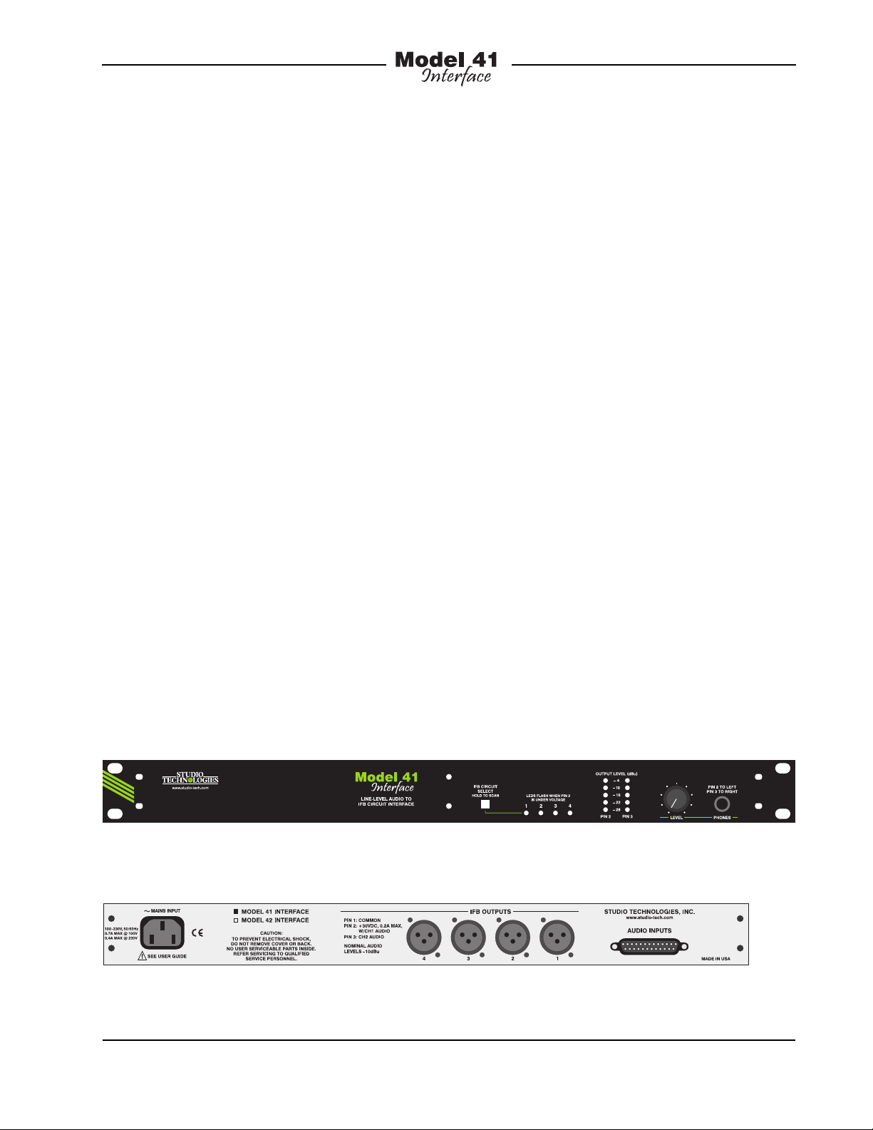
Model 41 Front Panel
Model 41 Back Panel
Model 41 User Guide Issue 1, October 2004
Studio Technologies, Inc. Page 5
Page 5

IFB circuits provide an effective means
of delivering power and two channels of
audio to user devices by means of standard audio cables. These cables, ubiquitous to the audio industry, interface using
3-pin male and female XLR-type connectors. With IFB circuits and standard audio
cables it’s a simple matter to support user
devices such as listen-only belt packs and
announcer’s consoles with no external
power source required. Whether 100 or
1000 feet apart, reliable operation can be
provided.
In many cases, the Model 41 Interface will
be used in on-air television applications.
Whether installed in a fixed location or as
part of a remote facility, excellent performance can be obtained. In addition, the
Model 41 is applicable for non-broadcast
applications. For example, audio recording and post-production facilities can also
effectively use the unit. Combined with
stereo or mono listen-only belt packs,
also available from Studio Technologies,
a variety of headphone cue systems can
easily be deployed. As the Model 41’s
audio inputs are compatible with standard
line-level audio signals virtually any analog
source can be connected.
to stereo or monaural headsets or headphones. Generally one source is configured in the matrix intercom system as
“interrupt” while the other is configured as
“program.” An alternate term often used
for the “interrupt” channel is “programwith-interrupt.” This may be more descriptive as the function is actually a program
source that gets interrupted with talkback
audio. The “program” channel is typically
a continuous source of program audio.
An alternate term is “program-only.” For
other applications, the Model 41’s audio
inputs can be connected to a 2-channel
or stereo audio source. This configuration
may prove useful in radio broadcasting,
audio-with-picture, or recording studio
applications.
Maintaining excellent audio performance
was a major Model 41 design goal—the
hiss, hum, and noise associated with
typical IFB circuits was simply not acceptable. The Model 41 meets those requirements with audio that is “on-air” quality:
low distortion, high signal-to-noise ratio,
and ample headroom. On-air talent and
guests, production personnel, and technicians will all appreciate the clean, quiet
cue signal.
Four Independent IFB Circuits
The Model 41 supplies four independent
IFB circuits. Each circuit consists of two
audio inputs and a “wet” IFB output circuit. The audio inputs are transformer
coupled, have a nominal level of +4 dBu,
and are compatible with balanced or
unbalanced sources. In on-air television
broadcast applications the audio sources
will often be analog outputs from matrix
intercom systems. Two sources are typically designated to feed user cue signals
power and two channels of unbalanced
audio over a single 3-conductor output.
The DC output is nominally 30 volts with
a maximum rated current of 200 milliamperes. A major strength of the Model 41
is the IFB circuit’s ability to effectively
deliver DC power over a variety of conditions. Unlike other interface devices that
use a common but less-than-ideal circuit
topology, a unique IFB circuit was developed by Studio Technologies to achieve
the desired performance goals. The result is a major improvement in effectively
Issue 1, October 2004 Model 41 User Guide
Page 6 Studio Technologies, Inc.
The Model 41’s IFB circuits provide DC
Page 6

supporting IFB user devices over a wide
range of conditions. Connected devices
can draw up to the full rated 200 milliamperes of current with little drop in DC
voltage. This output voltage stability is the
key—whether drawing 50, 100, or 200 milliamperes, the output will remain close to
30 volts. In practical terms this means that
reliable IFB-based cue systems can now
be deployed in more stadiums, concert
halls, or motor racing facilities than was
previously possible; longer cable runs,
more user devices, excellent performance.
Monitor Section
To help ensure proper installation and
operation, the Model 41 includes a sophisticated monitor section. Two 5-segment
LED meters provide an indication of the
IFB audio levels as they appear directly on
the output connectors. This unique feature
makes it simple to adjust and maintain the
correct level of the audio sources so as to
provide optimal IFB performance. A headphone output is also provided, allowing
“real world” checking of IFB audio quality.
In addition to being able to manually
select the IFB circuit to be monitored by
the meters and headphones, an “auto
scan” mode is included. This allows each
of the four IFB circuits to be monitored in
a continuously repeating sequence.
The DC output voltage present on pin 2
of each IFB circuit is also monitored. Four
LED indicators, one for each IFB circuit,
will “flash” if the voltage on its associated IFB circuit falls below the acceptable
value. Over-current or short-circuit conditions will no longer fall “below the radar,”
causing problems for IFB device users
with little chance of early detection.
Compatibility
The Model 41 is compatible with virtually every digital matrix intercom system,
including those from Clear-Com®, Drake,
RTS™, and Riedel Communications.
Interfacing requires only the connection
of analog output ports from the intercom
system to the Model 41’s audio inputs.
With the Model 41’s excellent audio and
power delivery performance it’s an ideal
alternative to the interface devices offered
by the intercom system vendors. Using
the Model 41 the intercom system’s audio
quality can be maintained all the way to
the IFB users.
The Model 41’s IFB circuits allow virtually
every IFB user device to be supported.
These include the Model 30-series listenonly belt packs and Model 200-series
announcer console products from Studio Technologies. The 200-series units
combine a variety of microphone control,
headphone monitoring, IFB and intercom
system interfacing, and related functions
into compact desktop units. Industrystandard listen-only belt packs from RTS,
including the 4020 and 4030, can also be
directly supported.
Alternate Applications
In addition to broadcast intercom applications, the Model 41 can be used to create
high-performance stereo headphone cue
systems. Stereo line-level signals coming
from audio consoles, routing switchers,
or off-air receivers can be connected to
the Model 41’s audio inputs. The IFB circuits can be connected to listen-only belt
packs, several models of which are available from Studio Technologies. For example, the Model 35 Talent Amplifier will allow
one or two pairs of stereo headphones to
Model 41 User Guide Issue 1, October 2004
Studio Technologies, Inc. Page 7
Page 7

be supported. Each of the four Model 41
IFB circuits will support up to six Model 35
Talent Amplifiers.
Installation
In this section you will be installing
and interconnecting the Model 41. The
one-rack-space unit will be mounted in
an equipment rack. Audio input connections will be made by way of a 25-pin
D-subminiature connector. IFB circuits will
be interfaced using four 3-pin XLR-type
connectors. AC mains power is connected
by means of a detachable cord set that is
compatible with the Model 41’s 3-pin IEC
320 C14-type inlet connector.
System Components
minimize cable length. In general, shorter
cables will lead to more reliable and
consistent system performance. It’s also
helpful if a technician can readily view and
access the monitor section that is located
on the right side of the Model 41’s front
panel. The output status LEDs and levels
meters can serve important roles in ensuring correct IFB circuit operation. Access
to the headphone output jack and level
control can also be useful.
Mounting the Model 41
Once the desired mounting location has
been selected, the Model 41 will require
one space (1.75 vertical inches) in a standard 19-inch (48.3 cm) equipment rack.
Secure the unit into the equipment rack
using two mounting screws per side.
The shipping carton contains the Model
41 Interface and associated user guide.
Units destined for North America and
Japan also include an AC mains cord.
Your dealer or distributor should provide
an AC mains cord for other destinations.
Locating the Model 41
The Model 41’s IFB circuits provide DC
power and unbalanced audio to operate
external IFB user devices. These devices
are often IFB “belt packs,” broadcast
announcer consoles, or other “talkback
boxes.” The Model 41’s mounting location will dictate the length of the cable
runs needed to link the unit with the connected devices. In some cases the location choice is already established. For
example, in field broadcast applications
the Model 41 will almost always be located
in a production truck or trailer. But in fixed
applications it may be possible to select
the Model 41’s mounting location so as to
Audio Input Connections
The Model 41 has eight line-level audio
inputs, arranged as four 2-channel pairs.
Each pair serves one of the four IFB circuits. Each IFB circuit, along with its two
associated audio inputs, is completely
independent. Literally any audio source
with a nominal operating level of +4 dBu
can be successfully connected. Transformer coupled, the inputs are compatible with balanced or unbalanced signals.
In many applications the analog outputs
from digital matrix intercom systems will
be connected to the Model 41.
For on-air television applications the IFB
sources are generally configured to provide a single- or dual-channel cue “feed”
to talent personnel. In such cases channel
one of a pair is generally designated as
the “interrupt” channel while channel two
is the “program” channel. For other broadcast applications, such as live radio, it’s
possible that a stereo cue source will be
Issue 1, October 2004 Model 41 User Guide
Page 8 Studio Technologies, Inc.
Page 8

Figure 1. Detail of back panel showing connector used for audio inputs
connected. In this situation the left source
would be connected to input channel one
while the right source would be connected
to input channel two. This might also
be the case with other professional audio
applications, such as recording and postproduction.
Audio input connections are made by way
of one female 25-pin D-subminiature connector which is located on the Model 41’s
back panel. A cable harness is required
with a 25-pin D-sub plug (male) on one
end and the desired mating connectors
on the other. This cable harness is not supplied by Studio Technologies. (Note that in
some locations the term “cable loom” may
be used instead of “cable harness.”) The
wiring scheme used by the D-sub complies
with the now-ubiquitous one made familiar
by TASCAM® with their DA-88® product.
A wiring harness prepared for connection
to the Model 41’s audio inputs is identical
to a DA-88-style input harness. Please refer
to Figures 2 and 3 for connection details.
Note that unlike a DA-88-style harness,
the Model 41’s D-sub connector’s holddown screws use 4-40 threads. This complies with the original design standard for
D-subminiature connectors which used
English rather than metric thread pitch.
The Model 41’s audio input circuits have
a nominal signal level of +4 dBu. They
are transformer coupled, have a nominal
impedance of 10 k ohms, and compatible
with balanced or unbalanced sources.
Balanced sources should be wired so that
signal high is connected to the + pins,
signal low to the – pins, and shield to the
shield pins. With unbalanced sources,
connect signal high to the + pins, and
shield to both the – and the shield pins.
Signal Signal
Connections High (+) Low (–) Shield
IFB Circuit 1-Interrupt 24 12 25
IFB Circuit 1-Program 10 23 11
IFB Circuit 2-Interrupt 21 9 22
IFB Circuit 2-Program 7 20 8
IFB Circuit 3-Interrupt 18 6 19
IFB Circuit 3-Program 4 17 5
IFB Circuit 4-Interrupt 15 3 16
IFB Circuit 4-Program 1 14 2
Notes: 1) Connector type on Model 41 is 25-pin
D-subminiature female. Installer must provide plug
(male). Connector uses 4-40 threaded inserts for
locking with mating plug.
2) Wiring scheme follows TASCAM DA-88 convention.
Standard DA-88-style wiring harnesses are directly
compatible, with the exception of 4-40 screw threads
being required.
Figure 2. Connections for Audio Inputs using
IFB Nomenclature
Model 41 User Guide Issue 1, October 2004
Studio Technologies, Inc. Page 9
Page 9

Signal Signal
Connections High (+) Low (–) Shield
IFB Circuit 1-Channel 1 24 12 25
IFB Circuit 1-Channel 2 10 23 11
IFB Circuit 2-Channel 1 21 9 22
IFB Circuit 2-Channel 2 7 20 8
IFB Circuit 3-Channel 1 18 6 19
IFB Circuit 3-Channel 2 4 17 5
IFB Circuit 4-Channel 1 15 3 16
IFB Circuit 4-Channel 2 1 14 2
Notes: 1) Connector type on Model 41 is 25-pin
D-subminiature female. Installer must provide plug
(male). Connector uses 4-40 threaded inserts for
locking with mating plug.
2) Wiring scheme follows TASCAM DA-88 convention.
Standard DA-88-style wiring harnesses are directly
compatible, with the exception of 4-40 screw threads
being required.
Figure 3. Connections for Audio Inputs using
Dual-Channel Nomenclature
If connecting an unbalanced source in
this manner results in hum or noise, try
connecting signal high to the + pins, and
shield to the – pins; leave the shield pins
unterminated.
As previously mentioned, the Model 41 is
compatible with matrix intercom systems
from Riedel Communications. Appendix
A, located near the end of this user guide,
provides detailed connection information.
IFB Circuits
As mentioned previously, the Model 41
has four independent IFB output circuits
each supplying DC power and two channels of unbalanced audio. The IFB circuits
are designed to connect to a variety of
devices that conform to the broadcast
IFB standard. In this implementation pin
1 is used for a combination of shield, DC
power return, and audio common; pin 2
supplies a combination of DC power and
one channel of unbalanced audio; pin 3
supplies a second channel of unbalanced
audio. The DC power supplied on pin 2 is
30 volts nominal with a maximum current
of nominally 200 milliamperes. The audio
superimposed on the DC power has a
nominal signal level of –10 dBu. Its audio
source is the channel one audio input
associated with that specific IFB circuit.
The audio on pin 3 also has a nominal
signal left of –10 dBu. Its audio source
is the channel two audio input channel
associated with that specific IFB circuit.
The Model 41’s IFB circuits are interfaced
using four 3-pin male XLR-type connectors which are located on the unit’s back
panel. The associated interface cables,
one for each IFB circuit, must be terminated with 3-pin female XLR-type connectors.
In most cases the IFB circuits should be
wired by way of an input/output connector
panel rather than directly to the external
devices. It’s also recommended that the
panel have “mults” (multiple connectors)
for each of the IFB circuits. For troubleshooting purposes it also may be useful
to have the IFB circuits pass through
points on an audio patch bay.
The type of interconnecting cable used
between the Model 41’s IFB circuits and
the user devices will vary by application.
In a fixed installation it would be typical
to use 22 AWG, shielded, stranded cable
in either a single- or 2-pair configuration.
With single-pair cable, pin 1 should be
connected to shield. Pins 2 and 3 would
connect to the cable pair.
If 2-pair cable is used, pin 1 should connect to one side of each pair, with pin 2
going to one side of pair one and pin 3
going to one side of pair two. The shields
Issue 1, October 2004 Model 41 User Guide
Page 10 Studio Technologies, Inc.
Page 10

Figure 4. Detail of back panel showing IFB circuit output connectors
can either go only to the XLR connector shells, or to both the connector shells
and pin 1. Shielding unbalanced audio
signals can be a tricky proposition. It is
recommended that the focus be on using
excellent twisted-pair cable, rather than
worrying about whether or not it is shielded. The typical foil shields used in much
of the contemporary audio cable generally
offers very limited effectiveness. The best
rule to follow is to try to minimize exposure
to large noise sources. (Okay, so that’s
hardly ever practical but at least it’s a
nice dream!)
In the event that very long cable runs are
required, the resistance of the cable can
impact the DC power supplied by the
Model 41. There’s no way to get around
the fact that some DC voltage will be
dropped by the interconnecting cable. A
simple ohms law calculation will tell you
the impact a specific cable run will have.
You’ll need to know the current draw of the
connected device(s), the minimum voltage required by the connected device(s),
and the resistance of the cable’s conductors. This is generally stated as ohms per
1000 feet. Make sure that you account for
the resistance in both the pin 1 and pin 2
legs! In general, if there is the potential for
a cable-length problem, moving to a more
substantial cable gauge, such as 20, 18,
or 16 can be effective.
AC Mains Power
The Model 41 operates directly from AC
mains power of 100 to 230 V, 50/60 Hz.
Being a “universal input” device, there
are no switches to set or jumpers to install to match a location’s nominal mains
voltage. For locations that have a mains
power source of 240 volts, contact Studio
Technologies for confirmation that a direct
connection can be made.
The Model 41 uses a 3-pin IEC 320 C14type inlet connector to mate with a detachable mains cord set. For units shipped to
North America and Japan a cord is supplied that has a North-American (NEMA
15L) standard plug on one end and an
IEC 320 C13-type connector on the other.
Units bound for other destinations require
that the appropriate cord set be obtained.
The wire colors in the mains cord must
conform to the internationally recognized
color code and should be terminated
accordingly:
Connection Wire Color
Neutral (N) Light Blue
Line (L) Brown
Earth/Ground (E) Green/Yellow
Model 41 User Guide Issue 1, October 2004
Studio Technologies, Inc. Page 11
Page 11

Safety Warning: The Model 41 does
not contain an AC mains disconnect
switch. As such, the AC mains cord
plug serves as the disconnection device. Safety considerations require that
the plug and associated inlet be easily
accessible to allow rapid disconnection of AC mains power should it prove
necessary.
As soon as AC mains power is applied
the Model 41 will begin its power-up sequence. As a “boot up” indication each of
the monitor section’s status LEDs will light
in an ascending order. After that has completed one of the status LEDs will remain
lit. The unit is now fully functional.
Figure 5. Detail of back panel showing AC
mains power connector
Post-Installation
Audio Input Source Level
Adjustment
It’s important to confirm and, if required,
adjust the level of the audio sources that
are connected to the Model 41’s inputs.
The monitor section’s dual 5-segment LED
level meters will help make this task simple. Begin by using the pushbutton switch,
located on the front panel, to select the
IFB circuit that is going to be calibrated.
Adjust the source levels so that the green
LEDs light when typical audio signals
are present. The desired nominal output
level of the IFB circuits is –10 dBu. This
is reflected in the top green LED being
calibrated to, and labeled, –10. The meters’ yellow LEDs, labeled –4, should light
infrequently, generally only when signal
peaks are present. Achieving a precise
level calibration is not critical. But getting
the levels within the optimum range is very
important!
It’s likely that the initial levels provided by
analog ports on a digital matrix intercom
system won’t be an exact match with the
Model 41’s inputs. This shouldn’t pose a
problem as the computer control available on contemporary intercom systems should make level adjustment very
simple. From our research we found that
the Clear-Com Eclipse™ system specifies a nominal level of 0 dBu. Since their
headroom is listed as greater than 18 dB,
increasing the nominal level of their analog output ports by 4 dB (to achieve the
desired +4 dBu) should be acceptable.
RTS in their ADAM™ and ZEUS™ systems
specify nominal output levels of +8 dBu.
With these systems correct Model 41
performance would be provided by reducing the ports’ output levels by 4 dB. With
the Artist™ system from Riedel, the analog
ports have a nominal level of +6 dBu. A
2 dB reduction in their output level would
be beneficial. In reality, a signal with a
nominal level that deviates somewhat from
precisely +4 dBu will be acceptable. But
with the power of contemporary computercontrolled intercom systems, there’s no
reason why a precisely calibrated system
can’t be easily implemented.
Issue 1, October 2004 Model 41 User Guide
Page 12 Studio Technologies, Inc.
Page 12

Audio Integrity
Monitor Section
At this stage the Model 41 should have
been installed and the input levels adjusted as required. The unit should now
be ready for many years of excellent performance. But before turning to another
task, performing a final Model 41 “reality
check” is highly recommended. Using
the monitor section, along with a pair of
high-quality stereo headphones, carefully
listen to each channel associated with the
four IFB circuits. Ensure that the correct
audio sources are assigned to the correct IFB circuits. Confirm that all interrupt
channels have the correct audio levels as
they switch from normal audio to interrupt
content. Overall, the audio quality should
be excellent, with no hum, noise, hiss, or
other objectionable content. Should any
issues be detected, now is the time to
work them out. Presenting IFB circuit users with a correctly implemented system
will make life better for everyone involved!
The Model 41’s monitor section allows
audible and visual monitoring of the audio
signals present on the four IFB circuits.
In addition, continuous monitoring of the
DC output voltages on the circuits is also
performed. The “heart” of the monitor section is logic circuitry created by a microcontroller integrated circuit and associated
firmware. This adds some “smarts” to an
otherwise pedestrian function. Using four
electromechanical relays, the monitor
section accesses the IFB circuits directly
on the Model 41’s output connectors.
This ensures that the impact of the actual
wiring and connected user devices is also
monitored, rather than just something
internal to the Model 41’s circuitry.
Operation
Overall, the Model 41 is designed for continuous operation with no adjustment or
maintenance required. On the input side,
maintaining the correct level coming from
the audio sources is very important. The
cabling that connects the Model 41’s IFB
circuits to the user devices must remain
free of full or partial short circuits. And
finally, the total current draw of the connected user devices must remain at 200
milliamperes or less. The monitor section
will help ensure that proper operation is
taking place. It will also prove invaluable
assistance should an issue arise.
Model 41 User Guide Issue 1, October 2004
Studio Technologies, Inc. Page 13
Figure 6. Detail of front panel showing four
status LEDs and associated pushbutton switch
Associated with the monitor section are
four status LEDs, one pushbutton switch,
two 5-segment LED level meters, a rotary level control, and a headphone jack.
The four monitor status LEDs are used to
display two conditions: the circuit being
monitored and low DC output voltage.
One of the LEDs is always lit, indicating
which of the four IFB circuits is currently
being monitored by the meters and headphone output. In addition, each status
LED will flash on and off should the level
Page 13

on pin 2 of its respective output connector
fall below 24 volts DC. This DC monitoring function is very powerful, allowing a
proactive approach to be taken should an
interconnecting cable or IFB user device
issue arise.
The pushbutton switch serves two purposes: selecting the source to be monitored
and enabling the auto scan feature. To
manually select an IFB circuit to be monitored, press and release the button until
the status LED associated with the desired
IFB circuit lights. Each press of the button will advance the circuit number to be
monitored by one. A delay is built into the
circuit selection process allowing a user to
move from, for example, circuit 1 to circuit
3. Simply by pressing the button twice in
rapid succession circuit 2 will be automatically skipped.
Unique to the Model 41 is its auto scan
feature. Pressing and holding the button
for two seconds will cause this feature to
begin operation. In this mode the monitor
source automatically “steps” through each
IFB circuit, pausing for eight seconds
before moving on to the next. Ideally, this
will allow technical personnel to observe
a problem through casual viewing of the
Model 41’s front panel.
The dual 5-segment LED level meters allow a direct observation of the audio levels
present on pins 2 and 3 of the selected
IFB circuit’s output connector. In television
broadcast settings, the left meter will typically display the “interrupt” signal while
the right meter will display “program.” A
quick glance at the meters will give an
accurate overall indication of a circuit’s
performance. Upon initial power up, the
meters may be observed “bouncing” each
time the IFB circuit selected for monitoring
Figure 7. Detail of front panel showing dual
5-segment LED level meters
changes. This is normal, caused by DC
blocking capacitors taking a minute or
two to reach their final state.
It’s important to note that the meters on
the Model 41 are calibrated differently
from the typical “VU” scale. The level
steps were selected so as to effectively
display the IFB circuit’s nominal –10 dBu
signal level. The ballistics of the meters
is also different, being a cross between
VU and peak. The bottom four LEDs are
green in color and indicate that signals are
in the normal range. The top LED, yellow
in color, lights when signals are 6 dB or
greater above –10 dBu. A correctly functioning IFB circuit should find signals lighting the four green LEDs, with the yellow
LED lighting only on peaks.
The headphone output allows audible
monitoring of the selected IFB circuit.
The 2-channel output is compatible with
virtually any pair of stereo headphones.
As the output circuitry meets “pro audio”
specifications, it’s recommended that
high-quality headphones be used. Pin 2
of the IFB circuit is the signal source for
the left channel of the headphone output.
Pin 3 of the IFB circuit is the source for the
right channel. The rotary control adjusts
the output level of both the left and right
Issue 1, October 2004 Model 41 User Guide
Page 14 Studio Technologies, Inc.
Page 14

Figure 8. Detail of front panel showing
headphone section
channels. Should it be necessary, there’s
no reason why the headphone output
couldn’t also be used as a line-level
monitor output.
Operating Parameters
As expected with professional equipment,
whenever mains power is disconnected
from the Model 41, the existing state of the
monitor section is stored in non-volatile
memory. This ensures that upon subsequent “power up” the unit will return to
how it was left. For example, if the auto
scan function was active when the Model
41 was powered down, auto scan will begin once mains power is again connected.
Troubleshooting
If you’re having trouble getting the Model
41 up and running, this section may help.
If you haven’t read the previous sections
of this guide, you should do so before
proceeding.
If the Model 41 Doesn’t Work
At All
A source of AC mains power must be
connected to the Model 41. The unit is
a “universal input” type so that applying
anything between 100 and 230 volts, 50/60
Hz is acceptable. Whenever mains power
is connected the four monitor status LEDs
should go through their power-up routine,
lighting one at a time in sequence. If this
does not occur confirm that AC mains
power is active (“hot”) and that the cord is
securely mated with the inlet connector on
the Model 41’s back panel.
In all foreseeable situations, both normal
and abnormal, the status LEDs should
go through the normal power-up routine.
However, it’s possible that if all four IFB
circuits are being presented with a shortcircuit condition, the internal 36 volt power
supply may enter its protection mode and
shut down. In this case no LED will light. If
the LEDs present this scenario, even after
confirming that mains power is correctly
being applied, try removing the loads from
the IFB circuits. The easiest way to do this
is to remove the 3-pin female XLR-type
connectors that are plugged into the Model
41’s back panel. If normal operation then
begins, carefully check the IFB circuit wiring for fault conditions.
If the status LEDs still don’t go through
their power-up routine, even after confirming that mains power is present and
that the IFB circuits are not shorted, it’s
likely that the unit requires factory service.
For safety in the event of a major internal
failure, the internal 36 volt power supply
contains a fuse in series with the incoming
mains power. This fuse will open (“blow”)
only if a serious failure occurs inside the
unit. The fuse is not field-replaceable.
The Model 41 must be returned to the
factory, or an authorized service location,
for review and repair.
Model 41 User Guide Issue 1, October 2004
Studio Technologies, Inc. Page 15
Page 15

Maintaining Correct Input
Signal Levels
The Model 41’s four 2-channel audio
inputs are designed for nominal signal
levels of +4 dBu. Applying signal levels
significantly lower than +4 dBu will
reduce the signal-to-noise ratio (raising
the perceived noise floor) and can prevent the connected user devices from
operating optimally. Applying signal levels
significantly higher than +4 dBu will reduce the headroom and greatly increase
the chance of reaching audio “clipping.”
Obviously, these cautions are not unique
to the Model 41, but apply to most audio
equipment. The front-panel level meters
provide an easy means of confirming that
the Model 41 is being presented with the
correct audio levels.
cause damage. Exceeding 200 milliamperes will cause the protection circuitry to
come into play. An overload condition will
cause the output voltage to shut off continually or intermittently. The exact action
will depend on the specific overload condition that is present. In general, the more
extreme the overload condition, the sooner normal operation will cease. Restoring
the output load to be within the rated 200
milliamperes will allow the output to again
operate normally. A few seconds may be
required from the time an overload condition is removed to when normal operation
will again take place. Please don’t test
the Model 41’s ability to sustain frequent
overload or short-circuit conditions! The
long-term reliability of the unit can be impacted by the stress caused by these fault
conditions.
To confirm correct IFB circuit operation
at locations away from where the Model
41 is installed, it’s possible to use the
Model 72 Level Meter/Interface, also available from Studio Technologies. The Model
72 is a compact, portable device that
plugs directly into IFB or intercom circuits
and provides two useful functions. Two
5-segment LED meters display the audio levels present on pins 2 and 3 of the
connected circuit. In addition, two “dry”
line-level audio outputs are provided.
Complete information on the Model 72
is available on the Studio Technologies
website.
Maintaining Correct IFB
Circuit Current Draw
Each of the four IFB circuits is designed
to provide up to 200 milliamperes of DC
current. By design, the IFB circuits are
protected so that an overload condition, or
even a complete short circuit, should not
The four status LEDs make it simple to
know if an excessive load, or a short circuit, is being placed on one or more of the
IFB circuits. The LEDs provide a direct indication of the IFB circuits’ DC output voltage. Each output voltage is directly related
to the amount of current being drawn, as
well as indicating when its output circuit
has entered protection mode and essentially shut down. During normal operation
the DC level on pin 2 of an output circuit
will range from approximately 28 to 30
volts. An LED will begin to flash on and off
if the level falls below approximately 24
volts DC. This will occur when the current
draw is greater than nominally 200 milliamperes. A complete short circuit condition will initially draw much more than 200
milliamperes and then change (due to
protection mode being entered) to being
only a few milliamperes. Even in protection mode, the output will remain much
less than 24 volts.
Issue 1, October 2004 Model 41 User Guide
Page 16 Studio Technologies, Inc.
Page 16

There’s really only one piece of advice
when it comes to understanding how
to use the under-voltage status LEDs: if
they’re flashing there’s a problem that
must be corrected! The most likely cause
will be a wiring fault that causes a partial
or full short circuit between pin 1 (common) and pin 2 (power with audio) on the
IFB circuit’s XLR-type output connectors.
Another cause can be due to problems
with the IFB user devices. Either a defective user device can be drawing too much
current, or too many user devices end up
being connected to the same IFB circuit.
Troubleshooting an IFB circuit problem
should prove quick and easy. Begin
by disconnecting the IFB user devices.
Observe the status LED and see if the
problem has gone away. If not, review the
interconnecting cables and find the fault
condition. Within a few seconds of the
problem being “cleared” the status LED
will stop flashing.
Determining the actual IFB circuit current
draw won’t often be required but can be
useful in a tough trouble-shooting situation. This measurement can be performed
using any good-quality digital multimeter.
Begin by setting the meter to measure
DC current. Then place the meter leads in
series with the pin 2 lead of the XLR-type
connector associated with the IFB circuit
to be tested. The easiest way to measure
the pin 2 current is to create a simple
adapter cable using one female and one
male 3-pin XLR-type connector. Connect
pin 1 on both connectors together. Connect pin 3 on both connectors together.
Connect separate wires to the pin 2 leads
on both connectors. Then connect the
meter leads to these two wires. The meter
will indicate the DC current being drawn
while normal operation of the connected
device(s) takes place. Be certain to connect the maximum number of devices
that might be powered by the IFB circuit.
That is, measure the worst-case condition
and ensure that the load is within the rated
200 milliamperes output. If possible, leaving a 10 or 20% reserve margin is a good
practice.
Technical Notes
Cable Length
There are no hard and fast rules defining
the maximum cable length possible when
connecting user devices to Model 41 IFB
circuits. The maximum cable length is
directly related to the amount of resistance
in the connecting cable; the lower the resistance per foot (or meter), the longer the
cable can be. (Although cable capacitance
affects high-frequency performance, resistance is the limiting factor in this case.) For
example, a standard 20 AWG microphonetype cable is Belden 8412, which has 10.9
ohms resistance per conductor per 1000
feet. Since we’re using two conductors
to carry the signal (pins 1 and 2) you’d
get 21.8 ohms per 1000 feet of cable. By
knowing the cable resistance value, along
with the minimum voltage and maximum
load current required by an IFB user device, a simple “ohms law” calculation will
tell you the maximum cable length.
Let’s use the example of a Studio Technologies Model 200 Announcer’s Console
being connected to a Model 41 IFB circuit.
We’ll select Belden 8412 as the interconnecting cable. For correct operation, the
Model 200 needs at least 24 volts DC
between pins 1 and 2 of its IFB input connector. It has a current draw of 95 milliamperes. The Model 41’s IFB circuit presents
Model 41 User Guide Issue 1, October 2004
Studio Technologies, Inc. Page 17
Page 17

an output voltage of 30 volts across pins 1
and 2 and can supply a maximum current
of 200 milliamperes. (As the Model 200’s
current draw is well within the Model 41’s
capability, this is not a limiting factor.) The
difference between the voltage supplied
by the Model 41 (30 volts) and the voltage required by the Model 200 (24 volts)
allows a 6 volt maximum drop over the
interconnecting cable. Using the current
draw and maximum voltage drop figures,
the maximum cable resistance can easily be calculated: 6 volts divided by 0.095
amperes equals 63 ohms. And finally,
with 8412’s 21.8 ohms (total) per 1000
feet of cable, a maximum of 2890 feet of
cable can be used and still be less than or
equal to 63 ohms. Using this example as
a guide, entering the appropriate values
will allow you to determine the maximum
cable length for your application.
Cabling Issues – Crosstalk
The Model 41’s IFB circuits conform to a
broadcast industry standard for sending
DC power and two channels of audio over
a single pair with shield audio cable. This
implementation allows standard portable
cables, such as are used for microphone
signals, to interconnect various IFB user
devices. This method is undoubtedly convenient and practical, but is not without
limitations. The main audio quality issue
is the possibility of crosstalk between the
two audio channels. This issue arises due
to the capacitance presented by the two
wires that form the twisted pair. The greater the capacitance presented and the longer the cable run, the greater the crosstalk
will become. Is this normally a problem
during actual use? No. But it’s something
that should be noted.
Studio Technologies did some experimenting with various cables and the crosstalk
that was created. For example, a 1000-foot
reel of 24-gauge 2-pair unshielded telephone cable was used to link a Model 41
IFB circuit with an IFB user device. One
pair carried the pin 2 (DC with channel 1
audio) and pin 3 (channel 2 audio) connections. One wire from the second pair
carried the pin 1 (DC and audio common)
connection. The inter-channel crosstalk
in the voice audio band was on the order
of –45 dB. Is this a good value for “professional” audio? Of course not. But for
the intended talent cueing applications it
should be fine. In almost all cases the audio signals being carried are somewhat or
fully phase-coherent. A bit of one channel
getting into the other won’t even be noticed, especially since monitoring is generally done using headsets, headphones, or
earpieces.
Is it possible to reduce the crosstalk that
is created? Absolutely, as long as a nonstandard cable connection is made. This
becomes a trade-off between an improved
crosstalk figure and ease of installation
and use. Using two full pairs can significantly reduce crosstalk. Several connection schemes are possible; the exact
one selected will depend on the specific
installation and personal technical philosophy. Two unshielded twisted pairs can be
effectively used. The first pair would carry
the DC and channel 1 audio signal and
common. The second pair would carry the
channel 2 audio signal, again along with
common. There will still be some capacitance between the conductors carrying
the two audio channels but it should be
significantly less. Two shielded pairs can
also be used as was discussed in the Installation section of this user guide.
Model 41 User Guide Issue 1, October 2004
Studio Technologies, Inc. Page 18
Page 18

Superior Power Delivery and
Audio Quality
As previously discussed, one of the Model
41’s strengths is its ability to very effectively deliver energy to the connected IFB
user devices. This allows more devices
to be supported over longer cable runs.
How does the Model 41 accomplish this?
Simply by having circuitry that is superior
to that used in most of the “industrystandard” equipment. In most IFB interface devices, an adjustable voltage
regulator integrated circuit is used as a
combination of audio modulator and current limiter. While this is a simple and inexpensive solution, it’s not without significant
limitations. The major problem with this
method is the type of voltage-current
“knee” that is created. As the load current increases past about 50% of the rated
maximum the output voltage begins to decrease. This means that the usable power
delivered to the connected device(s) will
start to drop well before the rated output
is reached. This limitation will become significant in applications that use long cable
runs. As the IFB circuit voltage begins to
drop problems with user device performance can occur. Contrast this situation
with the performance provided by the
Model 41. The DC voltage supplied by its
IFB circuits won’t “poop out” when loaded
over its 0 to 200 milliamperes range. This
will allow IFB belt pack and announcer’s
console devices to work correctly in many
more applications. Figure 9 shows the
IFB circuit voltage-current curves for the
RTS 4000-series and the Model 41 Interface. The performance differences are
quite interesting.
It’s interesting to note the reason why
typical IFB circuit audio quality is less
than pristine. It’s not hard to notice the
background “hiss” that is always present
on pin 2 (DC with channel 1 audio) of the
interface connector. Technically, it’s white
noise that comes from the adjustable
voltage regulator being used as an “AM”
modulator and current limiter. The noise is
an artifact of the design topology and simply can’t be overcome. How does Studio
Technologies know this? Because our first
“breadboard” designs used this method
and achieved the same poor results! Only
after the problem came to light did work
on an improved circuit begin. The results
were worth the effort.
Model 41 User Guide Issue 1, October 2004
Studio Technologies, Inc. Page 19
Page 19

35
4010
Model 41
30
25
20
Voltage (V)
15
10
5
0
0 50 100 150 200 250
Current (mA)
Figure 9. IFB Circuit Voltage-Current Curves for RTS 4000-Series and Model 41 Interface
Model 41 User Guide Issue 1, October 2004
Studio Technologies, Inc. Page 20
Page 20

Specifications
General Audio:
Frequency Response:
Pin 2 Outputs (DC with Channel 1 Audio):
20 Hz-20 kHz ±2.5 dB (80 Hz-20 kHz ±0.25 dB)
Pin 3 Outputs (Channel 2 Audio): 20 Hz-20 kHz
±0.25 dB
Distortion (THD+N): 0.01%, measured at 1 kHz,
+4 dBu, pin 2 outputs (DC with channel 1 audio)
S/N Ratio: 80 dB, ref +4 dBu out, 20 Hz-20 kHz,
pin 2 outputs (DC with channel 1 audio)
Crosstalk: 81 dB, typical, ref +4 dBu in, 20 Hz-20
kHz
Audio Inputs: 8, organized as four 2-channel
inputs
Type: transformer balanced, capacitor coupled,
compatible with balanced or unbalanced sources
Impedance: 10 k ohms, nominal
Nominal Level: +4 dBu
IFB Output Circuits: 4
Type: DC power with two channels of unbalanced
audio
Connections: common on pin 1, DC (+30 V
nominal) modulated with channel 1 audio (–10 dBu
nominal) on pin 2, and channel 2 audio (–10 dBu
nominal) on pin 3
Maximum Level:
Pin 2 Outputs (DC with Channel 1 Audio): +9 dBu
(+23 dBu on audio input)
Pin 3 Outputs (Channel 2 Audio): +14 dBu (+28
dBu on audio input)
Monitor Section – Headphone Output:
Type: stereo, drives headphones by way of 100
ohm series resistors
Compatibility: intended for connection to headphones with impedance of 100 ohms or greater
Maximum Voltage: 8 Vpp, 100 ohm load
Monitor Section – Output Voltage Detection:
Measures DC voltage level directly on pin 2 of IFB
circuit output connectors. Status LEDs flash when
level is less than approximately 24 volts DC.
Connectors:
Audio Inputs: 25-pin D-subminiature female,
4-40 threads
IFB Outputs: 3-pin male XLR-type
Headphone Output: ¼-inch 3-conductor phone
jack
AC Mains: 3-blade, IEC 320 C14-compatible
(mates with IEC 320 C13)
AC Mains Requirement:
100-230 volts, 50/60 Hz, 0.7 A maximum @ 100
volts, 0.4 A maximum @ 230 volts
Dimensions (Overall):
19.00 inches wide (48.3 cm)
1.72 inches high (4.4 cm)
9.58 inches deep (24.3 cm)
Mounting: one space in a standard 19-inch rack
Weight: 6.6 pounds (3.0 kg)
Specifications and information contained in this
User Guide subject to change without notice.
Model 41 User Guide Issue 1, October 2004
Studio Technologies, Inc. Page 21
Page 21

Appendix A
Interfacing Riedel Artist™ Matrix Intercom Systems with the Model 41 Interface
Information courtesy of
Riedel Communications Inc.
Model 41 User Guide Issue 1, October 2004
Studio Technologies, Inc. Page 22
Page 22

 Loading...