

Page 1

Model 40 Central Controller
and Related Components
User Guide
Issue 1, July 1994
© 1994 by Studio Technologies, Inc., all rights reserved
5520 West Touhy Avenue
Skokie, Illinois 60077 U.S.A.
Telephone (847) 676-9177
Fax (847) 982-0747
www.studio-tech.com
50065-794, Issue 1
Page 2

Tab le of Contents
Introduction ................................................................. 5
What This User Guide Covers ................................ 5
System Overview .................................................... 5
Model 40 Central Controller .................................... 5
Model 35 Talent Amplifier ....................................... 7
Model 38 Talent Amplifier ....................................... 7
Installation................................................................... 9
Configuration............................................................... 13
Operation .................................................................... 13
Model 40 Central Controller .................................... 1 3
Talent Amplifiers ..................................................... 1 4
Troubleshooting .......................................................... 15
Technical Notes .......................................................... 15
Circuit Description ....................................................... 17
Specifications .............................................................. 2 3
Appendix ..................................................................... 25
Block Diagrams
Model 40 Central Controller
Model 35/Model 38 Talent Amplifiers
Model 40 User Guide Issue 1, July 1994
Studio Technologies, Inc. Page 3
Page 3

This page intentionally left blank.
Issue 1, July 1994 Model 40 User Guide
Page 4 Studio Technologies, Inc.
Page 4

Introduction
The Model 40 Central Controller, along
with related components, are part of the
StudioComm series. StudioComm products provide monitoring and communications functions for professional audio
applications. The Model 40 Central
Controller, along with up to eight Model 35
or Model 38 Talent Amplifiers, allow the
creation of sophisticated headphone (cue)
systems for use in recording, broadcast,
film, and specialized applications. With a
totally unique, proprietary design, a specialized, high-quality headphone system
is easily configured and installed.
What This User Guide Covers
This User Guide is designed to assist
you when installing, configuring, and
using the Model 40 Central Controller,
Model 35 Talent Amplifier, and Model 38
Talent Amplifier. It also contains detailed
service information, including block and
schematic diagrams.
System Overview
cables to up to four Model 35 or Model 38
Talent Amplifiers. Two pairs of headphones can be connected to each talent
amp. By placing the final output stage in
the talent amplifiers, superior audio quality
can be delivered directly to the user.
The highlight of a StudioComm headphone system is the sonic quality; low
distortion, low noise “high fi” audio with an
output level loud enough for “rock ‘n roll.”
The entire audio path is optimized for one
thing: making headphones sound great.
The design and implementation of a
StudioComm headphone system is simple.
Cables terminated with standard 3-pin
XLR-type connectors link the Model 40
Central Controller with the talent amplifiers. For assistance, both input and loopthrough connectors are provided on
each talent amp. For the first time, cable
length simply stops being an issue.
Locating talent amplifiers over 500 feet
(164m) away from a Model 40 is perfectly
acceptable.
The underlying concept of a StudioComm
headphone system is distributed amplification. The Model 40 Central Controller
provides two stereo line inputs, each
which can be assigned to two output
groups. Each output group distributes linelevel stereo audio and DC power over
standard 3-conductor microphone-type
Model 40 User Guide Issue 1, July 1994
Studio Technologies, Inc. Page 5
Model 40 Central Controller
The Model 40 is the connection point for
the audio inputs, and provides the talent
amplifier outputs which connect to the
talent amplifiers. The unit mounts in one
standard rack space.
Page 5
Two Stereo Line Inputs
Talent Amplifier Output Groups
The analog outputs of consoles, workstations, off-air receivers, or virtually any
analog source can be connected to the
Model 40’s line inputs. The inputs accept
balanced or unbalanced signals, with an
acceptable input level range of –10dBV to
+10dBu. Signal Present LEDs provide
assistance when adjusting the input level
controls.
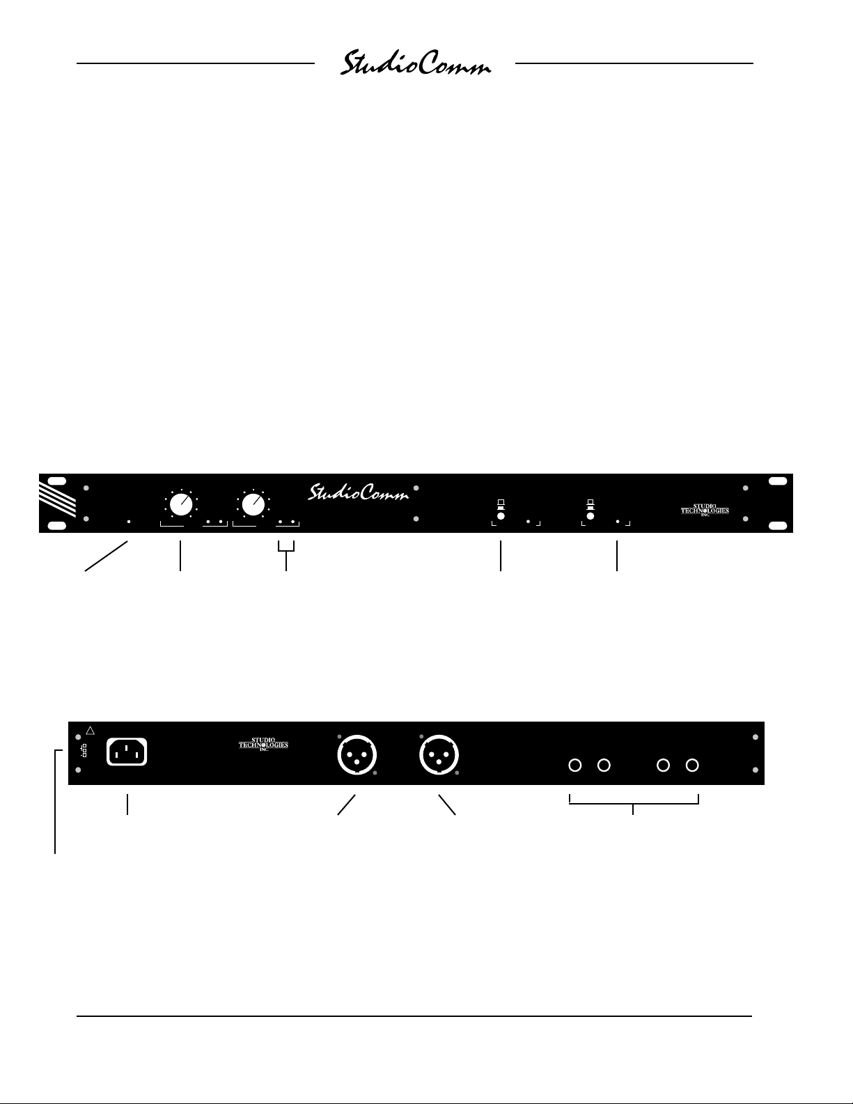
Model 40 Front Panel
POWER
INPUT LEVEL
INPUT 1
SIGNAL
PRESENT
LR
INPUT LEVEL
INPUT 2
SIGNAL
PRESENT
LR
MODEL 40 CENTRAL CONTROLLER
Each of the two output groups is designed
to feed up to four StudioComm talent
amplifier modules. The physical output
of each group is a 3-pin male XLR-type
connector that provides power and left
and right audio to the talent amplifiers.
The talent amplifier output groups are
short circuit protected. Error conditions
are displayed by the Over Current LEDs
on the Model 40’s front panel.
INPUT 1
INPUT 2
CURRENT
OUTPUT GROUP A
OVER
INPUT 1
INPUT 2
CURRENT
OUTPUT GROUP B
OVER
SKOKIE, ILLINOIS U.S.A.
Power
present LED
Input level adjustable
over –10dBV to
+10dBu range
Model 40 Back Panel
SEE INSTRUCTION MANUAL
!
100V
0.4A
120V
0.2A
220/240V
50/60Hz
AC mains
connection
Mains voltage
configuration chart
CAUTION:
TO PREVENT ELECTRICAL
SHOCK, DO NOT REMOVE
COVER OR BACK.
NO USER SERVICEABLE
PARTS INSIDE. REFER
SERVICINGTO QUALIFIED
SERVICE PERSONNEL.
Signal
Present LEDs
5520 WEST TOUHY AVE.
SKOKIE, IL 60077 U.S.A.
(708) 676-9177
MADE IN U.S.A.
Output to talent
TO TALENT AMPLIFIERS
OUTPUT B
amplifiers—
Group B
Switch between
Input 1 and 2 for the
Output Groups
TO TALENT AMPLIFIERS
OUTPUT A
Output to talent
amplifiers—
Group A
LEDs display
error conditions
MODEL 40 CENTRAL CONTROLLER
L
R
INPUT 2
Stereo line inputs
1 and 2
L
R
INPUT 1
Issue 1, July 1994 Model 40 User Guide
Page 6 Studio Technologies, Inc.
Page 6
Model 35 Talent Amplifier
Model 38 Talent Amplifier
The Model 35 Talent Amplifier is a portable amplifier unit capable of driving two
sets of high-impedance headphones
(>150Ω). The audio output is loud, and
very “clean.” The units feature a built-in
level control, a stereo/mono switch, and a
power present LED. A single microphonetype cable links the Model 35 with the
Model 40 Central Controller.
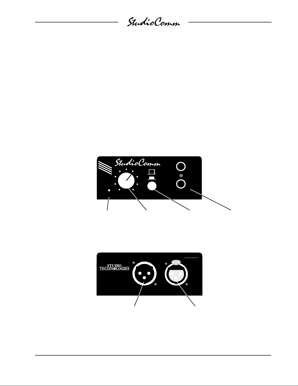
Model 35 Front Panel
The Model 38 Talent Amplifier takes the
basics from the Model 35 and adds a
unique stereo preamplifier section. This
allows a musician’s microphone or linelevel signal to be “looped” through the
Model 38, boosted by its preamp, and then
combined with the stereo cue mix supplied
by the Model 40. This allows the Model 38
user to create an individual headphone
1
STEREO
MONO (L+R)
2
OUTPUTLEVELPOWER
HEADPHONE
OUTPUT
Model 35 Back Panel
Power present
LED
MODEL 35 TALENT AMPLIFIER
5520 W. TOUHY AVE.
SKOKIE, IL. 60077
U.S.A.
Connects to additional
talent amplifiers
Headphone output
level control
Connects to the Model 40 or another talent
Switch between stereo
and mono (L+R) output
SN
PUSH
INPUTLOOP THRUMADE IN U.S.A.
amplifier’s loop thru connector
Two headphone
outputs
Model 40 User Guide Issue 1, July 1994
Studio Technologies, Inc. Page 7
Page 7
mix, solving the classic problem of wanting
“more me” in the phones! Like the Model
35, the Model 38 is linked with a Model 40
Central Controller by a single cable.
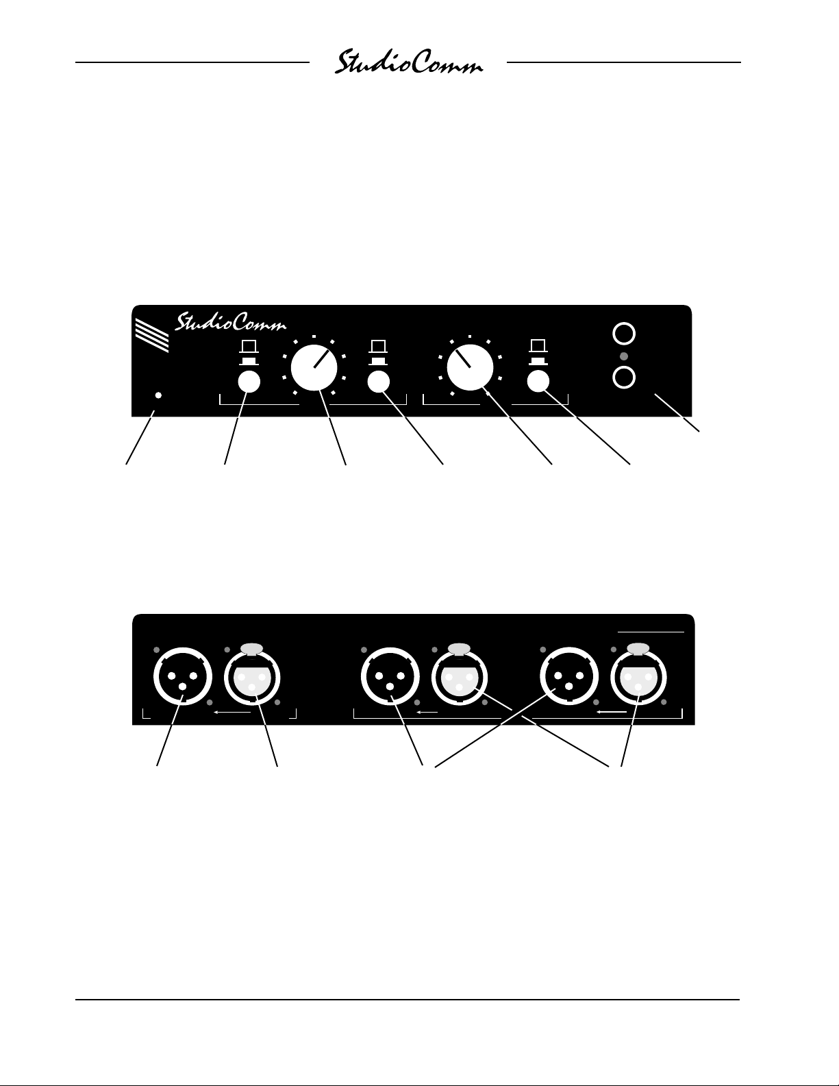
Model 38 Front Panel
MIC
LINE
POWER
Power
present LED
Mic/Line button switches
the talent input between
microphone and line level
Model 38 Back Panel
MODEL 38 TALENT AMPLIFIER
CUE MIX (FROM CENTRAL CONTROLLER)
LEVEL LEVEL
STEREO
MONO (L) MONO (L+R)
TALENT
Talent level
to phones
Switch between
stereo and mono
(L only) for the
talent input
STUDIO TECHNOLOGIES, INC., SKOKIE, IL U.S.A. (708) 676-9177
PUSHPUSH
MADE
IN
U.S.A.
LOOP THRU
CUE MIX
Cue mix level
to phones
TALENT
STEREO
LOOP THRUIN LEFT/MONO IN RIGHTLOOP THRU IN
1
2
HEADPHONE
OUTPUT
Two headphone
Switch between stereo
and mono (L+R) for
the cue mix
SN
PUSH
outputs
Connects to additional
talent amplifiers
Connects to the Model
40 or another talent
amplifier’s loop thru
connector
Loop thru connectors parallel the
talent inputs for routing to a digital
audio workstation, effects device,
microphone preamp, etc.
Connects to talent
sources such as key-
boards or microphones
Issue 1, July 1994 Model 40 User Guide
Page 8 Studio Technologies, Inc.
Page 8

Installation
In this section you will be installing the
Model 40 Central Controller in an equipment rack. Audio input connections will be
made. Wiring will be installed to allow
Model 35 or Model 38 Talent Amplifiers to
be connected. AC mains power will be
connected to the Model 40.
System Components
The main StudioComm shipping carton
contains a Model 40 Central Controller,
User Guide, and warranty card. Units
destined for North America are shipped
with an AC mains cord. Your dealer or
distributor will provide an AC mains cord
for non-North American destinations.
Model 35 and Model 38 Talent Amplifiers
will be contained in separate cartons.
Please check to ensure you have everything you need.
Sample Installation
Please refer to the following page for a
diagram detailing a possible Model 40 and
talent amplifier installation.
Mounting the Model 40
The Model 40 requires one space in a
standard 19-inch (48.3cm) equipment
rack. It is desirable to locate the Model 40
to allow easy access to both the front and
the back panels. The back panel contains
the input and output connectors, while the
front panel contains several controls,
switches, and LED indicators. The Model
40 is secured to the equipment rack using
two mounting screws per side.
Audio Inputs
The Model 40’s line-level audio input
connections are made using ¼-inch
3-conductor phone jacks. Don’t be con-
cerned about damage to your audio quality,
the jacks we use are manufactured by
Neutrik of Switzerland and feature goldplated contacts for excellent performance.
Caution: For reliable audio interconnection,
the plugs you use must comply with industry
standard RS-453. Switchcraft No. 297,
Neutrik NP3C, or equivalent will work correctly. Refer to the Technical Notes section
for details.
Stereo Line Inputs
The Model 40 allows two stereo line input
sources to be connected. During operation
either talent amplifier output group can
select either of the stereo inputs as its
source. This allows flexibility in routing the
desired source to the desired group of
talent amplifiers. In some installations only
one stereo source may be available. In this
case the one stereo source should be
connected to input 1. For future use it may
be wise to connect input 2 to points on a
patch bay. This will allow rapid connection
of another audio source should the need
arise.
The input circuitry is electronically balanced,
and is compatible with balanced or unbalanced signals that have a nominal level
range of –10dBV to +10dBu. The input
impedance is 50K ohms so that compatibility with virtually every source is assured.
Prepare the input plugs so that tip is positive (+ or hot), ring is negative (– or cold),
and sleeve is shield. The input jacks will
also accept unbalanced ¼-inch 2-conductor
phone plugs. With unbalanced phone plugs,
tip is positive (+ or hot) and sleeve is shield.
If 3-conductor phone plugs are used to
connect unbalanced input signals, connect
positive (+ or hot) to tip and shield to ring
and sleeve.
Model 40 User Guide Issue 1, July 1994
Studio Technologies, Inc. Page 9
Page 9
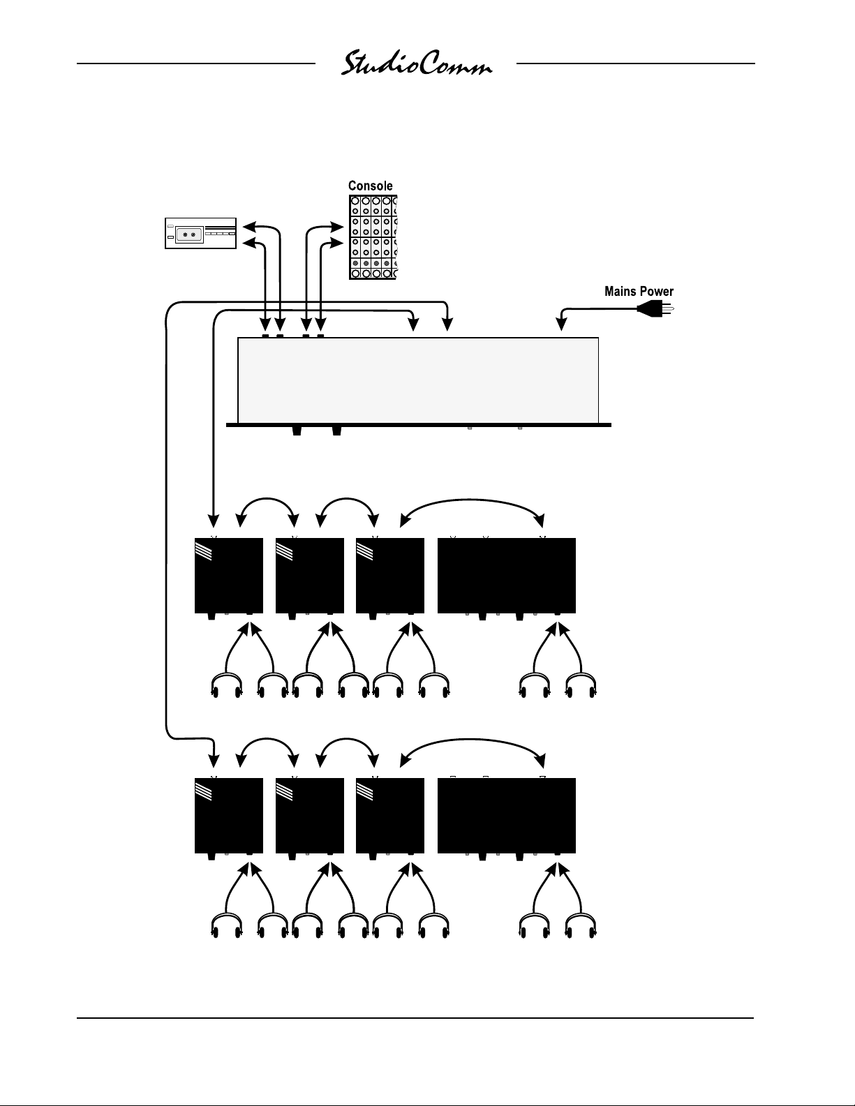
Example Installation
Recorder/Reproducer
Model 40 Central Controller
Model 35 Talent Amplifiers
Model 38 Talent Amplifier
Output Group 1
Output Group 2
Total of eight headphones per group
Issue 1, July 1994 Model 40 User Guide
Page 10 Studio Technologies, Inc.
Page 10

If one or both audio sources is monaural
several installation options are available:
• The mono signal is wired to both the
left and right inputs, thus sending
two channels of audio to the talent
amplifiers. This installation is simple,
but prevents the rapid connect of a
stereo source should the need arise.
• The mono source is connected to the
left input only. As both the Model 35
and Model 38 Talent Amplifiers contain
a monaural switch, talent amplifier
users can select to hear the signal in
both channels. This has the downside
of possibly confusing users who don’t
know to press the mono button.
• Our preferred installation has the left
and right inputs connected to points
on a patch bay. The mono source
would be connected to the “normal”
connections on both the left and right
patch points. This would feed the
mono signal to both the left and right
inputs, while giving the ability to
quickly “patch in” a stereo source.
Talent Amplifier Outputs
The Model 40 contains two talent amplifier
output groups which are designated Group
A and Group B. Each group will support up
to four Model 35 or Model 38 Talent Amplifiers in any combination. Two male XLRtype connectors are provided on the Model
40’s back panel for connecting to the
output groups.
Balanced Input
Connection
Ring (–)
Tip ( + )
Sleeve
(Shield)
(Switchcraft No. 297, Neutrik NP3C, or equivalent)
Unbalanced Input
Connection
Tip ( + )
Sleeve
(Shield)
(Switchcraft No. 280, Neutrik NP2C, or equivalent)
runs. Refer to the Technical Notes section
for additional information.
The simplest installation would use microphone cables to connect the Model 40 to
the first talent amplifier in each group; the
loop through connector on the first talent
amps sending the signal on to the next.
For convenience, you may want to wire
your facility to allow easy access to the
output groups at all locations where talent
amplifiers might be used. Talent amplifiers
connect to an output group in parallel, so
the connectors on the distribution panels
or mult boxes must be wired in parallel.
For best performance, use low-capacitance shielded microphone-type cable to
distribute the output groups. If you have a
choice, select cable with the heaviest wire
gauge commonly available. This will reduce voltage drop when using long cable
Model 40 User Guide Issue 1, July 1994
Studio Technologies, Inc. Page 11
Warning: Do not connect talent amplifier output signals to anything but Studio
Technologies’ talent amplifiers. Some
audio equipment may be damaged by
the +23Vdc contained on pin 2 of the
talent amplifier output group connectors.
Page 11

AC Mains Power
The Model 40 is internally configured to
operate from either 100, 120, or 220/240V,
50/60Hz. In most cases, units shipped to
North America are factory selected for
120V operation. Units bound for Japan are
selected for 100V, while our friends “down
under” and in Europe receive units set for
220/240V. Before connecting the Model 40
to mains power, check that it is configured
to match the local mains voltage. Look on
the back panel, adjacent to the power
entry connector, for the configured
voltage(s). Note than an incorrect configuration could seriously damage the unit.
Should it be necessary to change the
unit’s operating voltage it must be performed only at the factory or by an authorized service technician.
As soon as mains power is applied, the
Model 40’s power present LED will light.
The power present LEDs on the talent
amplifiers will also light.
The Over Current LEDs associated with
the output groups should not light. If either
or both are flashing, immediately refer to
the Troubleshooting section of this guide.
If everything appears to be functioning
properly you are now ready to configure
the system.
Model 35 Stand Mounting
Included with each Model 35 Talent Amplifier is a nifty mounting adapter that allows
the unit to be conveniently attached to a
microphone stand. Please refer to the
Installation Guide provided in the Model
35’s shipping carton for details.
The Model 40 uses an IEC standard
connector to mate with the AC mains cord.
The wire colors in the AC mains cord
should conform to the internationally
recognized CEE color code and must
be wired accordingly:
Connection Wire Color
Neutral (N) Light Blue
Line (L) Brown
Protective Earth (E) Green/Yellow
Safety Warning: The Model 40 does
not contain an AC mains disconnect
switch. As such the mains cord plug
serves as the disconnection device.
Safety consideration requires that the
plug and associated outlet be easily
accessible to allow rapid disconnection of mains power should it prove
necessary.
Model 38 Mounting Options
The Model 38 Talent Amplifier includes
provisions for mounting to microphone
stands, equipment consoles, etc. To avoid
“reinventing the wheel,” it was designed
for compatibility with the 25 Series of
components from OmniMount Systems,
Tempe, Arizona U.S.A. (602) 829-8000, a
supplier of finely engineered mounting
systems. This firm makes many versions
of the 25 Series; one of which should fit
your needs. If you desire microphone
stand mounting the following components
would be appropriate for English-thread
applications: 25RST-25H Straight Tube
Reverse Mount with Quick Release, along
with a 25MA Microphone Stand Adapter.
(If quick adjustment is not required the
25RST Straight Tube Reverse Mount can
be used in place of the first item.) When
connecting to metric-thread stands please
contact OmniMount for the correct part
numbers.
Issue 1, July 1994 Model 40 User Guide
Page 12 Studio Technologies, Inc.
Page 12

The bottom surface of the Model 38 Talent
Amplifier contains two threaded inserts that
will accept English-standard ¼-20 screws.
Using two,
chine screws, the 25 Series clamp assembly can be directly attached. The cover of
the Model 38 does not have to be removed.
5
/8-inch long, round-head ma-
Configuration
Input Level Calibration
Optimal performance of the Model 40 and
associated talent amplifiers depend on the
correct setting of the input level controls.
Each of the two stereo input sections contain an input level potentiometer and two
Signal Present LEDs. The level control is a
stereo device, adjusting the input sensitivity
for both the left and right inputs. The Signal
Present LEDs are provided for assistance
during adjustment of the pot, as well as for
general signal present indication.
The following is a step-by-step procedure
for using an input control to match an input
signal to the Model 40:
• Slowly turn the level control clockwise.
As you increase the level, watch the
Signal Present LEDs. The correct
setting is just at the point where both
LEDs light.
• For future reference it may be helpful
to mark the correct input level and
right trim adjustment points. Use a
grease pencil or a piece of adhesive
tape so as not to damage the front
panel.
• Disconnect the 1kHz signal and
connect the normal audio source.
Operation
Now that you’ve installed and set the input
level controls, you’re ready to go. You
should find system operation very easy, as
there is almost nothing to do on a day-today basis except adjust the output levels
on the talent amplifiers. For peace of mind,
the Signal Present LEDs will give you a
visual indication whenever audio signals
are present on the Model 40’s inputs.
• Set the input control fully counterclockwise (all the way to the left end of the
travel).
• Supply a 1kHz sine wave to both the
left and right line inputs. Set the level
of the source to be precisely the
nominal operating level. If, for
example, the output of a console is
connected to the input of the Model 40,
the console output should be adjusted
so that the meters read 0dB or 100%.
If the output of the console is a
“+4-type,” then setting the console’s
left and right output levels to nominal
should find the console output levels to
be exactly +4dBu.
Model 40 User Guide Issue 1, July 1994
Studio Technologies, Inc. Page 13
In most cases the input level controls
shouldn’t be changed, as they will effect
the input calibration. If you change the
input source you can use the input level
control and the Signal Present LEDs to
recalibrate the input.
Model 40 Central Controller
The Model 40’s front panel contains seven
LEDs, two controls, and two switches.
The power present LED should be lit
whenever AC mains power is connected
to the Model 40. During normal operation
the two Over Current LEDs will not be lit.
They will flash only if there is a problem
with a talent amplifier or associated wiring.
Page 13

Refer to Troubleshooting section if either
Over Current LED lights.
The Signal Present LEDs will light whenever a signal of “reasonable” level is
connected to its respective input.
Talent Amplifiers
Warning: Protect your ears! The
StudioComm talent amplifiers are
capable of driving headphones to
extremely high sound pressure levels.
Hearing experts advise against continuous extended play, especially at high
levels.
Model 35 Talent Amplifier
The power present LED should be lit
whenever the Model 35 is connected to an
operating Model 40. The Model 35 has a
level control and a stereo/mono switch.
You can plug in one or two pairs of headphones with a total impedance of 75 ohms
or greater. Turn the knob to the output
level you want and select stereo or mono
by pressing the button. Both headphone
outputs are controlled by the one level
control. The Mono button sends L+R to
both the left and right output.
Model 38 Talent Amplifier
The Model 38 has the unique ability to
provide a personalized headphone mix for
the in-studio talent. The performer’s audio
can be connected to the talent inputs and
passively looped through to the control
room. This lets performers increase their
level in the headphone mix without an
engineer getting involved. The Model 38’s
circuitry was carefully designed to not
interfere with the talent audio as it passes
through.
The Model 38 has all the functions of the
Model 35, plus it provides personal mix
controls. The power present LED should
be lit whenever the Model 38 is connected
to an operating Model 40. You can plug in
one or two pairs of headphones with a
total impedance of 75 ohms or greater.
The Cue Mix Level control sets the headphone output level for the signal coming
from the Model 40. The Cue Mix Stereo/
Mono button switches both headphone
outputs between a stereo and mono (L+R)
feed of the cue mix.
The Model 38 allows connection of a
stereo or mono talent signal at microphone
or line level. If your talent source is stereo,
connect it to the In Left/Mono and In Right
connectors and set the Talent Stereo/
Mono switch for stereo operation. With a
mono source, use only the In Left/Mono
connector and set the Stereo/Mono switch
for mono operation. This will feed the
mono talent source to both left and right
headphone channels. Connect loop
through cables as needed for feeds to the
control room.
The Talent Mic/Line switch is used to
select the input sensitivity, matching the
talent source with the Model 38’s input
circuitry. When you connect a microphone
or direct box, select Mic. When keyboards
or other preamplified sources are connected, select Line. The expected signal
level in the Mic position is –40 to –60dBu.
In the Line position it’s –10 to +10dBu. If
you are unsure of your signal level, start
with input sensitivity set for Line. If the
output level is not sufficient, turn down the
talent level control, switch to Mic, then
listen as again you raise the level control.
Issue 1, July 1994 Model 40 User Guide
Page 14 Studio Technologies, Inc.
Page 14

The talent level control works just like you
would guess: turn it up for more talent
signal in the headphone mix, and turn it
down for less. The talent and cue mix level
controls work like a mixer for the headphone outputs, so you can have any level
you want of either source in the headphone mix.
Troub leshooting
If you’re having problems getting the
StudioComm system up and running, this
section can help. If you haven’t read the
other sections of this guide, you should do
so before proceeding.
Talent Amplifier Over Current LED
During normal operation the talent amplifier Over Current LEDs should not light.
They will flash on and off if a talent amplifier output group is loaded to exceed its
maximum output current. The most common reason for an over current condition
would be a shorted interconnecting cable.
Also, connecting more than the specified
maximum of four Model 35 or Model 38
Talent Amplifiers to each group can also
cause the LED to light. A possible, but not
likely, cause would be a fault condition
within a Model 35 or Model 38.
If an LED does flash, troubleshooting
should prove quite simple. Begin by disconnecting the cable that is plugged into
the applicable talent amplifier output group
connector. Perform the disconnection
directly on the Model 40’s back panel. The
LED should stop flashing. Now check
through all the wiring to determine where
the short circuit condition is located. The
Model 40 will not be damaged if the Over
Current LED is flashing so you should use
it to help you locate the fault in your system. In just a few minutes you should be
able to isolate exactly what cable or talent
amplifier is causing the problem.
Intermittent Audio Connections
Should you experience audio connections
that seem to be “flaky” or intermittent, refer
to the Technical Notes section of this
guide. The ¼-inch 3-conductor phone
jacks used on the StudioComm products
are of very high quality, conforming to the
industry standard EIA RS-453. Some
plugs do not meet this standard, specifically in the shape of the tip conductor. In
rare cases you may have to replace plugs
on interconnecting cables or headphones
to remedy an interconnection problem.
Switchcraft No. 297 or Neutrik NP3C
phone plugs will function correctly.
Technical Notes
Talent Amplifier Cable Length
There are no hard and fast rules defining
the maximum cable length when connecting Model 35 or Model 38 Talent Amplifiers to the Model 40 Central Controller.
The maximum cable length is directly
related to the amount of resistance in the
connecting cable; the lower the resistance
per foot (or meter), the longer the cable
can be. (Although cable capacitance
affects high frequency performance, resistance is the limiting factor is this case.)
To lay out the facts in grammar-school
story problem format: for correct operation, a Model 35 or Model 38 needs to see
at least +20Vdc between pins 1 and 2 of
their input connector. The Model 40’s
talent amplifier output voltage across pins
Model 40 User Guide Issue 1, July 1994
Studio Technologies, Inc. Page 15
Page 15

1 and 2 is +23Vdc, with a maximum current draw of 0.2A (200mA). This difference
between the voltage supplied and the
voltage required results in a maximum
voltage drop of 3V over the interconnecting cables. Since cable is rated in ohms
per 1000 feet (or ohms per 1000 meters),
you need to know what the maximum
cable resistance is. This can be easily
calculated by dividing the maximum voltage drop by the maximum current flow: 3V
divided by 0.2A = 15 ohms. For example,
a standard 20 AWG microphone cable is
Belden 8412, which has 10.9 ohms resistance per conductor per 1000 feet. Since
we’re using two conductors to carry the
signal (pins 1 and 2) you’d get 21.8 ohms
per 1000 feet of microphone cable. With
our 15 ohm maximum resistance you’d be
able to use 688 feet (210m) of this cable.
By using the numbers provided, along with
the resistance of your specific cable, you
can select a cable, and its maximum
length, for your application.
¼-Inch Plugs versus EIA RS-453
An incompatibility problem lurks between
some ¼-inch 2-conductor and 3-conductor
phone plugs and the jacks found on professional audio equipment. While all the
plugs seem to “look” the same, some do
not comply with the industry standard,
called EIA RS-453. This standard defines
the physical dimensions, including the
shape of the plug’s tip. It seems that some
plug manufacturers don’t bother to make
the tip comply with the standard. Why is
this relevant to you? Because the phone
jacks used on the Model 40 Central Controller, Model 35 Talent Amplifier, and
Model 38 Talent Amplifier do comply with
the standard. They expect to be mated
with plugs that also meet the specification.
When interfacing your line inputs or headphones be careful with the plugs you
utilize. Should a connection appear “flaky,”
sound noisy, or make intermittent contact,
the most likely problem is a non-standard
phone plug. Replace the plug if this is the
case. You should find that all plugs from
Switchcraft or Neutrik will work correctly,
specifically Switchcraft No. 297 or Neutrik
NP3C. In our experience, headphones are
the most likely place to find non-standard
plugs—we even found them on some
“world-class” headphones that we use in
our lab!
Definition of Level—dBu and dBV
Whenever possible, Studio Technologies
has opted to use the dBu designation as it
seems to be quite rational. Using dBm was
fine when all audio line outputs were
terminated with 600 ohm loads. In this way
it was easy to say that 0dBm is 1 milliwatt
dissipated in the known load (i.e., 0dBm
across 600 ohms will measure 0.7747V).
In contemporary situations an output is
rarely terminated with 600 ohms; generally
10k ohms or higher. The dBu designation
is better because it refers to dB referenced
to 0.7747V, with no reference to load
impedance. This takes into account
today’s audio scene where signals have
a low source impedance and a high input
impedance. The dBu designation is becoming the standard for the professional
audio industry.
The Model 40 is designed to interface with
audio signals that have nominal signal
levels of –10dBV to +10dBu. You might
wonder why dBV came into the picture.
Most people don’t realize that equipment
that utilizes “–10” levels usually mean
–10dBV—substantially different from
–10dBu (–10dBV = –7.78dBu). The dBV
Issue 1, July 1994 Model 40 User Guide
Page 16 Studio Technologies, Inc.
Page 16

designation is simply a different way of
measuring signal level and is often used
when dealing with portable or consumer
audio equipment. The dBV designation
refers to dB referenced to 1.0V, rather
than dBu which refers to 0.7747V.
Talent Amplifier Mono Function
Many arguments where had while designing the talent amplifier monaural function.
Was mono to be the sum of left and right
sent to both left and right channels? What
about level build up with phase coherent
signals that are in both the left and right
channels? After much head scratching it
was realized that the mono function that
most people are accustomed to is not
really a “true” mono function, but is the
sum of the left and right signals, dropped
in level by 3dB, and connected to the left
and right outputs. This is what is implemented in the Model 35 and Model 38
Talent Amplifiers.
Input Level and the Talent Amplifiers.
Optimal performance of Model 35 and
Model 38 Talent Amplifiers depends on
the proper setting of the Model 40’s input
level controls. The headphone volume is
intended to be adjusted only by the level
controls on the talent amplifiers. If the
setting of the input level control vis-a-vis
the actual level of the source is not correct, the talent amplifier will simply not be
able to create the maximum volume in the
headphones or will exhibit excessive
distortion.
The Model 38 Talent Amplifier can also
exhibit reduced performance if the level
of the input source is significantly “hotter”
than nominal. The entire system has
plenty of headroom, but maintaining
proper signal levels, as usual, is important.
If the input level is excessive, a small
amount of bleed-through can be heard
with the Model 38’s cue mix level control
set fully counterclockwise. Instead of
having no sound in the phones, a bit of
sound can be heard. This is not a design
problem; the Model 38 has a sensitive
preamplifier section which doesn’t like
“seeing” excessive excursions in the left
channel modulation of the +23Vdc signal.
The Model 38’s power supply can reject
the left channel modulation within the
design parameters, creating a clean reference voltage for the stereo preamplifier.
Modulation levels outside the design
parameters show up in the reference
voltage!
Cir cuit Description
The information contained in this
section is not provided as an
endorsement for you to perform
repairs or modifications to StudioComm
components. Removing the cover or the
back panel from the Model 40 Central
Controller exposes personnel to hazardous voltages. Repairs or modifications
should be performed only at the factory
or authorized service center.
Model 40 Central Controller
This information will help you understand how the Model 40 functions and,
if required, help you identify where a
failure may be located. Please refer to the
attached block and schematic diagrams
while reading this material.
Model 40 User Guide Issue 1, July 1994
Studio Technologies, Inc. Page 17
Page 17

Power Supplies
The Model 40 contains two independent
linear power supply circuits. We felt that
reliability would be enhanced by splitting
the circuitry into two main groups, and
then optimizing a power supply for each.
Using this scheme, the Model 40 will
operate reliably, even with wide swings
in ambient temperature, varied operating
duty cycles, and mains voltage fluctuations. The result is a unit that should prove
quite hard to kill! The power supplies use
separate step down transformers, the
primary side of each containing two 115V
windings. This allows them to be configured for nominal mains voltages of 100V,
120V, or 220/240V. For 100V and 120V
operation the primaries are connected in
parallel; for 220/240V operation they are
connected in series. The configuration is
performed using jumper straps on the
printed circuit board. For safety, a fuse is
in series with the incoming mains power.
Because the Model 40 is intended for
continuous operation, a power switch is
not included. This serves several purposes: eliminating the chance of a power
switch being accidently turned off, increasing the physical isolation between the
nasty 50/60Hz fields and the sensitive
analog circuitry, and eliminating the
physical space required by a switch.
The first power supply generates filtered
and regulated ±15Vdc. The two 18V secondaries are connected in series, with the
series connection point providing circuit
common, as well as being strapped to the
metal chassis and the ground pin of the
power entry connector. The transformer’s
secondary is fed to a full wave diode
bridge. The output of the bridge is filtered
with electrolytic capacitors, producing
nominal ±22Vdc. Two integrated circuit
regulators produce the ±15Vdc from the
unregulated voltages. Capacitors on the
outputs of the regulators provide stability.
The ±15Vdc is utilized by most of the
analog circuitry.
Interesting technical note department:
notice that a diode is connected from the
output pin of each regulator to circuit
common. These serve to keep the ±15Vdc
rails at, worst case, one diode drop (0.7V)
away from ground. The +15V regulator
will, worst case only, go to –0.7Vdc; the
–15V regulator to +0.7V. This is important
when supplying bipolar loads, such as
operational amplifiers, etc. Without these
diodes the regulators can “latch-up” when
mains power is applied or removed. When
mains power is initially applied one of the
supplies can “come up” (get to its operating voltage) sooner than the other. This
voltage is fed back through the loads (the
op-amps) to the output pin of the other
regulator that is still coming up to full
voltage. Upon seeing this unexpected
opposite polarity voltage on its output pin,
the regulator may get very unhappy,
possibly latching into a nonoperating state,
drawing lots of current, burning up, etc.!
The protection diodes keep this condition
from happening.
The second power supply generates two
unregulated DC voltages: +V UNREG,
which ranges from approximately +30 to
+55Vdc, and +V LED which ranges from
+15 to +28Vdc. Its transformer has dual
15V secondaries for 120V and 220/240V
operation, and dual 17V secondaries for
100V operation. The secondary windings
are connected in series, and then go to a
full wave diode bridge and an electrolytic
filter capacitor. The negative pin of the
Issue 1, July 1994 Model 40 User Guide
Page 18 Studio Technologies, Inc.
Page 18

bridge is connected as the circuit common, as well as being strapped to the
metal chassis and the ground pin of the
power entry connector. +V UNREG is
used by the talent amplifier output group’s
power modulator circuitry. The center tap
of the transformer creates +V LED—can
you figure out how this works? For filtering, an electrolytic capacitor is connected
from +V LED to circuit common.
circuit, followed by a variable gain reduction stage. The line input signals are direct
coupled to SSM-2141 differential (balanced) line receiver integrated circuits.
The ’2141 has excellent common mode
rejection, low noise, and high slew rate. It
contains two internal 25k ohm series input
resistors, individually laser trimmed for
accuracy. By design, the ’2141 acts as
a unity-gain device.
For service assistance, several test points
are included on the printed circuit board:
±15Vdc, +V UNREG, and circuit common.
Analog Circuitry
The Model 40 takes advantage of an
excellent series of audio-specific integrated circuits from Analog Devices. Using
these parts saved us from using literally
hundreds of additional components. More
importantly, performance levels were
achieved that would have been difficult,
if not impossible, to obtain with more
conventional circuitry. These Analog
Devices parts have the common prefix of
SSM, indicating their roots in a company
called Solid State Microelectronics for
Music, purchased, by way of Precision
Monolithics, a few years ago. Hats off
to the guys and gals at Analog Devices!
Line Inputs
The Model 40 contains two identical
stereo line input circuits. The line inputs
are compatible with balanced or unbalanced signals with nominal levels of –
10dBV to +10dBu. The exact purpose of
the line input circuits is to receive the
audio signal, separate out common-mode
hum and/or noise, unbalance the signal,
and attenuate it to the –10dBu internal
operating level. Each line input circuit
contains a differential input integrated
The output of the SSM-2141 is capacitive
coupled to one section of dual potentiometer. The coupling capacitor is a nonpolar type, allowing for small DC voltages
of unknown polarity to be received on a
line input. The wiper of the pot is connected to one section of op amp configured as an inverting, unity-gain buffer. The
output of the op amp serves as the internal
signal “bus.”
Signal Present LEDs
Four identical signal present circuits monitor the audio level on the internal audio
buses; left and right for input 1, and left
and right for input 2. Audio signals enter
each meter circuit via an operational amplifier configured as a half-wave synchronous
rectifier. The resulting DC output is
smoothed via a resistor/capacitor low pass
filter. The output of the low pass filter is
connected to the input of one section of
integrated circuit comparator. Two precision resistors are connected in series with
the +15Vdc power supply rail to create a
DC reference voltage. This reference
voltage is used as the switching point for
the comparator. The output of the comparator is used to control the base lead of
a transistor, a transistor which directly
controls the Signal Present LED.
Model 40 User Guide Issue 1, July 1994
Studio Technologies, Inc. Page 19
Page 19

Talent Amplifier Output Groups
Over Current Detection
Two identical circuits are used to create
talent amplifier output groups A and B.
Each circuit provides power and stereo
audio for connecting up to four Model 35
or Model 38 Talent Amplifiers. One circuit
will be described. A double-pole/doublethrow switch selects which audio bus is
connected to the output group. From the
switch, signal connects to sections of
operational amplifier which are configured
as inverting, unity-gain amplifiers. The
selected op-amps are capable of driving
low impedance loads.
The output of the op-amp that serves the
left channel is capacitive coupled to a
power modulator circuit. The power modulator circuit provides the talent amplifiers
with nominal +23Vdc, amplitude modulated with left channel audio at a nominal
level of –10dBu. The modulator consists of
a 3-terminal regulator integrated circuit,
two transistors, and several discrete components. The voltage regulator creates
nominal +26Vdc from +V UNREG. The
regulator has inherent thermal protection
so that an over-current condition will not
damage the circuitry. One of the transistors is used as the actual modulator. It is
connected in a series-pass arrangement,
with the left channel audio connected to its
base. The other transistor, along with a
resistor, serves to limit the maximum
current.
The second section of op-amp provides
right channel audio to the output group.
A capacitor, along with a series resistor
protects the op amp from capacitive loads,
as well as from an accidental short circuit
to the power/left channel signal.
Two identical circuits monitor the operating
status of the talent amplifier output groups;
we will describe one. The +23Vdc with left
channel audio output signal is connected
to a network consisting of two precision
resistors and a filter capacitor which
serves as a voltage divider/filter. The
scaled voltage is connected to one section
of integrated circuit comparator. The
switching point of the comparator is set by
a reference voltage that is created from
the +15Vdc power supply rail. The output
of the comparator is used to control the
base lead of a transistor, which in turns
controls the Over Current LED. The LED
lights whenever the output voltage falls
below the threshold.
Model 35 Talent Amplifier
General Description
The Model 35 Talent Amplifier is a selfcontained module which allows headphones to be driven with stereo audio
provided by a talent amplifier output group
from the Model 40 Central Controller. The
major components of the Model 35 are the
power supply and headphone amplifier.
The Model 35’s circuitry is contained on
two printed circuit boards which are interconnected via a 5-conductor flexible
jumper cable. All active circuitry lies on the
electronics board; the connectors lie on
the connector board. No surprises here!
Power Supply
A 3-terminal adjustable integrated circuit
voltage regulator is configured to provide
+19V from the incoming +23V that is
modulated with left channel audio. The
important characteristic of this circuit is its
constant input impedance. The input
impedance is fixed at a moderately high
Issue 1, July 1994 Model 40 User Guide
Page 20 Studio Technologies, Inc.
Page 20

value, approximately 2K ohms, and does
not vary appreciably with load. This is
important so that the left channel audio
signal is not significantly attenuated, nor
distorted by normal fluctuations in the
power draw. A moderately large capacitor
is connected across the output of the
regulator. This capacitor provides a reserve of energy to allow the left and right
channel audio amplifiers to respond with
gusto when encountering audio transients.
An LED indicator shows that +19V power
is present. Two resistors and a capacitor
create a +9.5V reference. This reference
is used to set the operating point of the
circuitry.
Audio Amplifier
Two identical amplifier circuits provide the
left and right headphone outputs. The
circuits are designed to produce a maximum voltage swing, rather than to source
a large amount of power. This is the correct means of driving contemporary headphones, most of which have a load
impedance of 250 ohms or higher. The
reality is that with most phones a high
output level is obtained via a large voltage
swing, not through power.
For simplicity, only the left channel circuit
will be described. Audio enters the amplifier via an electrolytic capacitor and is
connected to a log taper potentiometer.
The “pot” is used to set the output level.
From the pot the signal is connected to
one section of integrated circuit operational amplifier via resistors and a switch
which performs the mono function. In the
mono position the switch connects the left
channel signal to the right channel amplifier, while dropping the level by 6dB. The
op amp, along with two transistors and
supporting components form the left
channel output stage. A low pass filter in
the feedback loop helps to provide stability. The amplifier’s output is capacitor
coupled, via a series resistor, to the output
connectors. The capacitor changes the
audio output signal from being biased at
approximately +9.5V, to being biased at
signal common. The series resistor limits
the output current in the event of a shorted
output load. The output capacitor was
selected for sonic performance, rather
than what the math told us to select. We
used our ears, not the numbers!
Model 38 Talent Amplifier
General Description
The Model 38 Talent Amplifier is a selfcontained module which allows headphones to be driven with a mix of audio
from the Model 40 Central Controller,
along with another signal that we refer to
as the talent signal. The talent signal can
be stereo or mono, microphone or line
level, allowing an individual headphone
mix to be created.
The major components of the Model 38
are the power supply, talent preamplifier,
and headphone amplifier. The Model 38’s
circuitry is contained on two printed circuit
boards, which are interconnected via two
5-conductor flexible jumper cable. All
active circuitry lies on the electronics
board; the connectors lie on the connector
board.
Power Supply
A 3-terminal adjustable integrated circuit
voltage regulator is configured to provide
+19V from the incoming +23V that is
modulated with left channel audio. The
important characteristic of this circuit is its
constant input impedance. The input
Model 40 User Guide Issue 1, July 1994
Studio Technologies, Inc. Page 21
Page 21

impedance is fixed at a moderately high
value, approximately 2K ohms, and does
not vary appreciably with load. This is
important so that the left channel audio
signal is not significantly attenuated, nor
distorted by normal fluctuations in the
power draw. A moderately large capacitor
is connected across the output of the
regulator. This capacitor provides a reserve of energy to allow the left and right
channel audio amplifiers to respond with
vigor when encountering audio transients.
An LED indicator shows that +19V power
is present. Two resistors and a capacitor
are used to create a low-impedance
reference voltage of approximately +9.5V.
This reference voltage is used to set the
operating point for all the analog circuitry.
Talent Preamplifier
Two identical sections of preamplifier
serve the talent input. For clarity we will
describe only the section that serves the
left/mono input. Signal enters the preamplifier via blocking capacitors. These are
specifically provided to block +48V
phantom voltage that may be present on
microphone signals. From the blocking
capacitors the signal enters one section of
operational amplifier that is configured to
act as a differential amplifier. This allows
balanced or unbalanced signals to be
connected.
A switch controls the gain of the op amp,
providing a voltage gain of 20dB when set
to the microphone position, or an attenuation of 30dB when set to the line position.
Signal diodes protect the inputs of the
op amp from destruction due to an
over-voltage condition. Compensation
capacitors are provided to ensure stability
at the two gain settings. (Note that the
gain set switch is a four-pole/double-throw
type, allowing one switch to control both
preamplifier sections.)
The output of the op amp is connected to
one section of a dual audio-taper potentiometer. This pot is the user control that
sets the level of the talent signal fed to the
headphone outputs. Signal from the wiper
of the pot is capacitive coupled to the input
of another section of operation amplifier.
This op amp has a fixed voltage gain of
25dB. The output of this op amp is
connected to the left headphone amplifier
and the talent input stereo/mono switch. In
the stereo position the output of the left
preamp is connected only to the input of
the left headphone amp; the output of the
right preamp is connected to the input of
the right headphone amp. In the mono
position the output of the left preamp is
connected to the inputs of both the left and
right headphone amps; the right preamplifier is not connected to anything.
Headphone Amplifier
Two identical amplifier circuits provide the
left and right headphone outputs. The
circuits are designed to produce a maximum voltage swing, rather than to source
a large amount of power. This is the correct means of driving contemporary headphones, most of which have a load
impedance of 250 ohms or higher. The
reality is that with most phones a high
output level is obtained via a large voltage
swing, not through power. For simplicity,
only the left channel circuit will be
described.
Cue mix audio (audio from the Model 40)
enters the amplifier via an electrolytic
capacitor and is connected to a log taper
potentiometer. The “pot” is used to set the
output level of the cue signal. From the pot
the signal is connected to one section of
Issue 1, July 1994 Model 40 User Guide
Page 22 Studio Technologies, Inc.
Page 22

integrated circuit operational amplifier via
resistors and a switch which performs the
mono function. In the mono position the
switch connects the left channel signal to
the right channel amplifier, and drops the
level by 6dB. The op amp is configured as
a summing amp, allowing the signal from
the cue mix pot to be summed (mixed)
with the signal from the talent preamplifier.
Talent Amplifier Output Groups: 3-pin XLR-type,
male (Neutrik)
AC Mains: standard 3-blade plug, meets IEC 320
specifications
Audio Inputs
Qty: 2, stereo (separate left and right input
connectors)
Type: electronically balanced, direct coupled,
compatible with balanced or unbalanced signals
The op amp, along with two transistors
and supporting components form the left
channel output stage. A low pass filter in
the feedback loop is included for stability.
The amplifier’s output is capacitor coupled
via a series resistor to the output connector. The capacitor changes the audio
output signal from being biased by the
+9.5V reference voltage to being biased at
signal common. The series resistor limits
the output current in the event of a shorted
output load.
Specifications
Model 40 Central Controller
Mounting
One space in a standard 19-inch (48.3cm) rack
AC Mains Requirement
100, 120, or 220/240V, ±10%, factory configured,
50/60Hz, 100-120V 0.4A maximum, 220/240V
0.2A maximum
Fusing
Qty: 1
Type: 5 x 20mm time lag (Littelfuse 218-series or
equivalent)
Impedance: 50k ohms
Nominal Input Level: –10dBV to +10dBu
Input Level Control: allows calibration over –10dBV
to +10dBu input range
Maximum Input Level: +27dBu balanced, +21dBu
unbalanced
Common Mode Rejection: 100dB @ DC and 60Hz,
70dB @ 20kHz, 62dB @ 40kHz (typical)
Talent Amplifier Outputs
Application: provides power and audio signals for
two groups of up to 4 Model 35 or Model 38 Talent
Amplifiers (total 8 talent amplifiers). The output
connectors (3-pin XLR-type, male) have common
on pin 1, +23Vdc modulated with left channel
audio at –10dBu on pin 2, and right channel audio
at –10dBu on pin 3. Maximum output current
200mA (nominal)
Frequency Response, Distortion (THD+N),
S/N Ratio: refer to Model 35 and Model 38
specifications
LED Indicators
Qty: 7, power present, signal present (4), over
current (2)
Dimensions (Overall)
19.00 inches wide (48.3cm)
1.72 inches high (4.4cm)
8.75 inches deep (22.2cm)
(1 standard rack space)
Rating: 0.400A for 100 and 120V mains power,
0.200A for 220/240V mains power
Connectors
Audio Inputs: dual, ¼-inch, 3-conductor phone
jacks, gold-plated contacts. (Manufactured
by Neutrik.) Mates with all plugs specified by
EIA RS-453.
Model 40 User Guide Issue 1, July 1994
Studio Technologies, Inc. Page 23
Weight
8.8 pounds (4.0kg)
Page 23

Model 35 Talent Amplifier
Mounting
Desktop. Provision for stand mounting available as
option.
Power Requirements
+20-32Vdc (modulated with left channel audio),
provided by Model 40 Central Controller
Connectors
Cue Mix Input (from Model 40): 3-pin XLR-type,
female (Neutrik)
Cue Mix Input Loop Thru: 3-pin XLR-type male,
connected in parallel with input connector (Neutrik)
Talent Input (Left In/Mono and Right In): 3-pin
XLR-type, female (Neutrik)
Power Present LED
Red LED indicates presence of operating power
Connectors
Input (from Model 40): 3-pin XLR-type, female
(Neutrik)
Loop Thru: 3-pin XLR-type, male, connected in
parallel with input connector (Neutrik)
Headphone Outputs: 2, ¼-inch, 3-conductor
(stereo) phone jacks, gold-plated contacts
(Neutrik)
Headphone Output
Qty: 1, feeds two headphone jacks
Load: intended for connection to one or two pairs
of headphones with total impedance of 75 ohms or
greater
Output Level: user adjustable
Maximum Output Voltage: 16V peak-to-peak into
150 ohms @ 1% THD+Noise, 400Hz
Distortion (THD+N): 0.03%
Frequency Response: 20Hz-20kHz ±0.5dB
Dimensions (Overall)
4.2 inches wide (10.7cm)
2.0 inches high (5.1cm)
5.3 inches deep (13.5cm)
Weight
0.8 pounds (0.4kg)
Talent Input Loop Thru: 3-pin XLR-type male,
connected in parallel with input connectors
(Neutrik)
Headphone Outputs: 2, ¼-inch, 3-conductor
(stereo) phone jacks, gold-plated contacts
(Neutrik)
Cue Mix Input
Intended for connection only with Model 40 Central
Controller
Talent Input
Qty: 1, stereo or mono, switch selectable
Type: electronically balanced, capacitor coupled,
input impedance 20k ohms
Input level: switch selectable for microphone or
line-level signals. Expected signal level: Mic
position –40 to –60dBu, Line position –10 to
+10dBu.
Headphone Output
Qty: 1, feeds two headphone jacks
Load: intended for connection to one or two pairs
of headphones with total impedance of 75 ohms or
greater
Output Level: user adjustable
Maximum Output Voltage: 16V peak-to-peak into
150 ohms @ 1% THD+Noise, 400Hz
Distortion (THD+N): 0.1%
Frequency Response: 20Hz-20kHz ±0.5dB
Model 38 Talent Amplifier
Mounting
Desktop. Provision for stand mounting provided.
Power Requirements
+20-32Vdc (modulated with left channel audio),
provided by Model 40 Central Controller
Power Present LED
Red LED indicates presence of operating power
Issue 1, July 1994 Model 40 User Guide
Page 24 Studio Technologies, Inc.
Dimensions (Overall)
8.0 inches wide (20.3cm)
2.0 inches high (5.1cm)
5.4 inches deep (13.7cm)
Weight
1.5 pounds (0.7kg)
Specifications and information contained in this
User Guide subject to change without notice.
Page 24

Appendix
Block Diagrams
The following block diagrams are
contained in this guide:
Model 40 Central Controller
Model 35/Model 38 Talent Amplifiers
Model 40 User Guide Issue 1, July 1994
Studio Technologies, Inc. Page 25
Page 25

This page intentionally left blank.
Issue 1, July 1994 Model 40 User Guide
Page 26 Studio Technologies, Inc.
Page 26

Page 27

 Loading...