

Page 1

Model 372A Intercom Beltpack
User Guide
Issue 1, April 2019
This User Guide is applicable for serial numbers
M372A-00151 and later with application firmware 1.1 and later
Copyright © 2019 by Studio Technologies, Inc., all rights reserved
www.studio-tech.com
50691-0419, Issue 1
Page 2

This page intentionally left blank.
Page 3

MODEL 372A
INTERCOM BELTPACK
Table of Contents
Revision History ........................................................... 4
Introduction ................................................................... 5
Getting Started ............................................................. 8
Operation ...................................................................... 13
Technical Notes ............................................................ 17
Specifications ............................................................... 21
Appendix A ................................................................... 22
Model 372A User Guide Issue 1, April 2019
Studio Technologies, Inc. Page 3
Page 4

Revision History
Issue 1, April 2019:
• Initial release.
MODEL 372A
INTERCOM BELTPACK
Issue 1, April 2019 Model 372A User Guide
Page 4 Studio Technologies, Inc.
Page 5
MODEL 372A
INTERCOM BELTPACK
Introduction
The Model 372A Intercom Beltpack is
a highly compact user-worn device that
combines a single channel of talk and two
channels of listen. The unit begins with the
features offered by traditional analog partyline (PL) intercom user devices and adds
a range of new capabilities, along with the
advanced performance and flexibility that
Dante® audio-over-Ethernet provides. Over
a standard IP network, multiple Model 372A
and other compatible Studio Technologies’
beltpack units can be used to create partyline intercom applications with help from an
external Dante-enabled audio matrix such as
the Studio Technologies’ Model 5422 Dante
Intercom Audio Engine. Alternately, Model
372A units can be used “point-to-point” or
interfaced with Dante-compatible matrix
intercom systems.
Having one talk and two listen channels may
seem unconventional. But it can be ideal
for many “real-world” applications. Often
an intercom user is primarily listening and
non-verbally responding to requests made
by producers, directors, or stage managers.
Typically, the Model 372A will be configured
to be part of one talk-and-listen party-line
intercom channel. During the time that an
event is taking place the listen function will
serve a much more important role; the talk
function will rarely be utilized. However, the
second listen channel will often be important.
Typically, it will be designated as a programlisten or “show audio” channel. The two
listen channels, along with the ability to
receive and display call signals, allow the
Model 372A to very effectively support production personnel in a compact and costeffective manner.
Only a single Power-over-Ethernet (PoE)
connection is required for operation. Key
user features can be easily configured using
the STcontroller software application. Configurable parameters include electret microphone powering, microphone preamplifier
gain, talk button operation, and headphone
channel assignment. Features include
integrated sidetone, call signal receive
display, and remote mic kill (“talk off”). The
range of capabilities, along with the excellent
audio quality provided by the digital audio
signal path, offers a unique and powerful
user experience.
Setting up and configuring a Model 372A
is simple. An etherCON® RJ45 receptacle
is used to interconnect with a standard
twisted-pair Ethernet port associated with a
local-area network (LAN). This connection
provides both power and bidirectional digital
audio. The Model 372A is compatible with
both broadcast and “gaming” headsets.
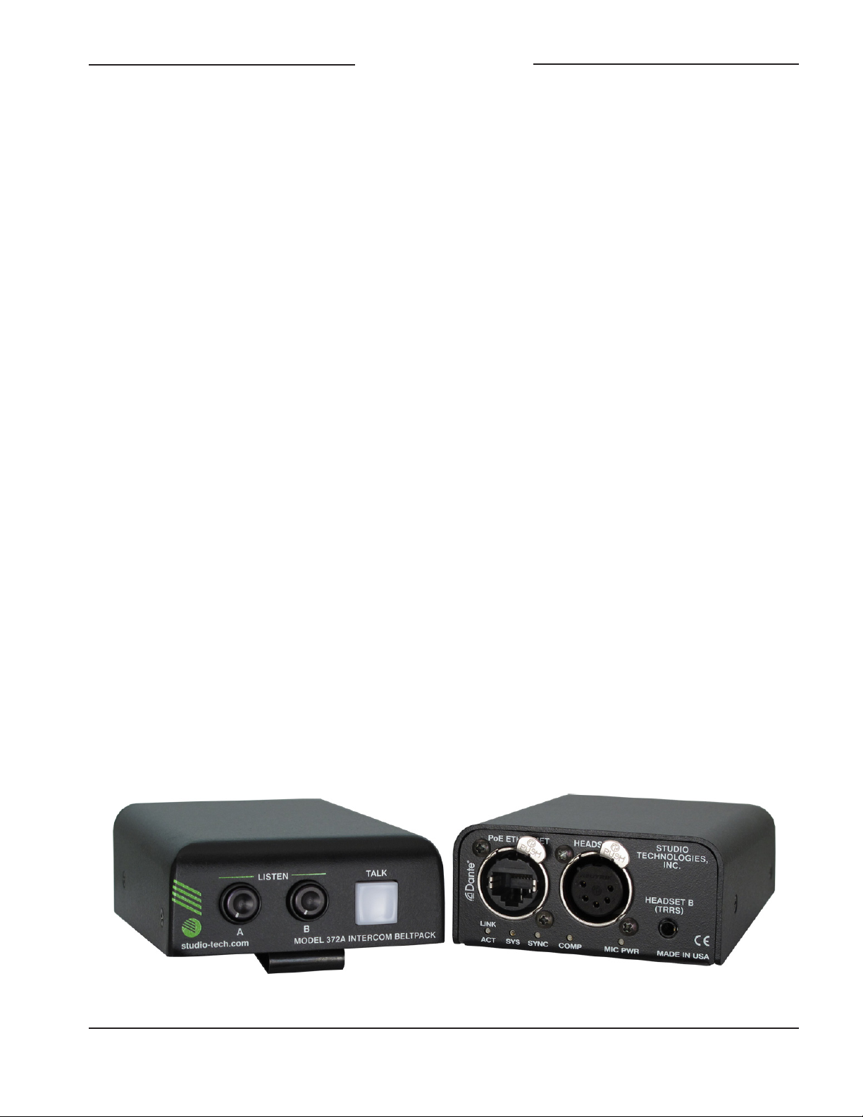
Figure 1. Model 372A Intercom Beltpack top and bottom views
Model 372A User Guide Issue 1, April 2019
Studio Technologies, Inc. Page 5
Page 6

MODEL 372A
INTERCOM BELTPACK
A broadcast or intercom-style headset with
a dynamic or electret (DC-powered) microphone can be interfaced with the Model 372A
using a 5-pin XLR connector. The Model
372A also directly supports connection of
earbuds or gaming headsets that utilize a
3.5 mm 4-conductor TRRS plug. These moderately priced devices, commonly associated
with mobile phones or personal computers,
are often of high-quality and may be preferred for some applications. With the Model
372A’s moderate price and ability to support
a broad range of headset devices the overall
cost of deploying an intercom system can
often meet budget goals.
The STcontroller software application is used
to select the unit’s operating parameters. The
talk pushbutton switch can be configured for
optimal operation. Two “push-in/push-out”
(“pop-out”) rotary controls make it easy to set
and maintain the desired headphone output
level. The Model 372A’s compact enclosure
is made from an aluminum alloy which offers
both light weight and ruggedness. A stainless
steel belt clip, located on the back of the unit,
allows direct attachment to a user’s clothing.
The audio quality of the Model 372A is excellent, with low distortion, low noise, and high
headroom. Careful circuit design and rugged
components ensure long, reliable operation.
A wide range of applications can be supported, including education and commercial
theater, sports and entertainment TV and
radio events, streaming broadcasts, corporate and government AV, post production,
and aerospace.
and two audio input (Dante receiver) channels can be interconnected (routed) with other
devices using the Dante Controller software
application. The Dante transmitter and receiver channels are limited to supporting four
Dante flows, two in each direction. The digital
audio’s bit depth is up to 24 with a sampling
rate of 48 kHz. The Model 372A is AES67
compatible and compliant with the Dante
Domain Manager™ software application.
Two bi-color LEDs provide status indications
of the Dante interface. The Dante Identify
command takes on a unique role with the
Model 372A. Not only will it cause the talk
pushbutton’s orange LED to light in a highly
visible sequence, it will also turn off (“kill”)
the talk function if it is active.
Audio Quality
The Model 372A offers “pro” audio performance that is not found in typical party-line
(PL) intercom beltpacks. A low-noise, wide
dynamic-range microphone preamplifier and
associated voltage-controlled-amplifier (VCA)
dynamics controller (compressor) ensures
that microphone audio quality is preserved
while minimizing the chance of signal overload. DC power to support electret microphones can be enabled as required. The
output of the microphone preamp and compressor is routed to an analog-to-digital converter (ADC) section that supports a sampling
rate of 48 kHz with a bit depth of up to 24.
The audio signal, now in the digital domain,
travels through the processor and on to the
Dante interface section where it is packetized
and prepared for transport over Ethernet.
Dante Audio-over-Ethernet
Audio data is sent to and received from the
Model 372A using the Dante audio-overEthernet media networking technology. As a
Dante-compliant device, the Model 372A’s
Audio input signals arrive via two Dante
receiver channels. The supported sampling
rate is 48 kHz with a bit depth of up to 24.
The audio signals pass into the Model 372A’s
processor where channel routing, headphone
one audio output (Dante transmitter) channel
Issue 1, April 2019 Model 372A User Guide
Page 6 Studio Technologies, Inc.
Page 7

MODEL 372A
INTERCOM BELTPACK
level control, and sidetone creation are
performed within the digital domain. This
provides flexibility, allowing precise control
of the audio signals and eliminating the need
for the two rotary level controls from having
to directly handle analog audio signals. The
audio signals destined for the 2-channel
headphone output are sent to a highperformance digital-to-analog converter
and then on to robust driver circuitry. High
signal levels can be provided to a variety
of headsets.
Call Function Receive
A call receive function allows Model 372A
users to be provided with a visual indication
that a call signal is active. The orange LED
within the pushbutton switch will first flash
then light solid whenever a call signal is detected on either of the Dante receiver (input)
channels. Using 20 kHz tones, the call signals are sent within the Dante audio channels
(“in band”) allowing interoperability between
multiple Studio Technologies’ beltpack units
as well as being compatible with legacy partyline intercom systems. Call signals can be
useful to indicate to users that they are needed “on headset” or should be actively listening to an intercom channel. The call function
can also be used to provide real-time cues to
production personnel during the running of
live events.
Configuration Flexibility
A highlight of the Model 372A is its ability to
be easily configured to meet the needs of
specific users and applications. All configuration choices are made using the STcontroller
software application that communicates with
the Model 372A by way of an Ethernet network connection. Configurable parameters
include microphone power and preamplifier
gain, headphone monitoring, sidetone audio
operation, and talk button operation.
The microphone input can be selected for
compatibility with dynamic or electret (DCpowered) microphones. The gain of the
microphone preamplifier can be selected
from among five choices. These choices
allow compatibility with the variety of microphones that are part of broadcast, intercom,
and computer gaming headsets.
To support optimum user performance, the
Model 372A’s talk pushbutton switch can be
configured from among three choices: Push
to Talk, Latching, or Push to Talk/Tap to
Latch. Two audio channels arrive via Dante
receivers (inputs) and are destined for the
2-channel headphone output. Each input
source can be independently routed to the
left headphone channel, right headphone
channel, or both the left and right headphone
channels. This flexibility allows a variety of
listening environments to be created, including stereo, single-channel monaural, and
dual-channel monaural.
Ethernet Data and PoE
The Model 372A connects to an Ethernet
data network using a standard 100 Mb/s
twisted-pair Ethernet interface. The physical interconnection is made by way of a
Neutrik® etherCON RJ45 receptacle. While
compatible with standard RJ45 plugs,
etherCON allows a ruggedized and locking
interconnection for harsh or high-reliability
environments. An LED displays the status
of the network connection.
The Model 372A’s operating power is provided by way of the Ethernet interface using
the 802.3af Power-over-Ethernet (PoE) standard. This allows fast and efficient interconnection with the associated data network. To
support PoE power management, the Model
372A’s PoE interface reports to the power
sourcing equipment (PSE) that it’s a class 1
(very low power) device.
Model 372A User Guide Issue 1, April 2019
Studio Technologies, Inc. Page 7
Page 8

MODEL 372A
INTERCOM BELTPACK
Future Capabilities and
Firmware Updating
The Model 372A was designed such that
its capabilities and performance can be
enhanced in the future. A USB connector,
located on the unit’s main circuit board (underneath the unit’s cover), allows the application firmware (embedded software) to be
updated using a USB flash drive.
The Model 372A uses Audinate’s Ultimo™
integrated circuit to implement the Dante
interface. The firmware in this integrated circuit can be updated via the Ethernet connection, helping to ensure that its capabilities
remain up to date.
Getting Started
What’s Included
Included in the shipping carton are a Model
372A Intercom Beltpack and a printed copy
of this guide. As a device that is Power-overEthernet (PoE) powered, no external power
source is provided. In most applications an
Ethernet switch with the required PoE capability will be utilized.
Connections
In this section signal interconnections
may be made using the three connectors
located on the bottom of the Model 372A’s
enclosure. An Ethernet data connection
with Power-over-Ethernet (PoE) capability
will be made using either a standard RJ45
patch cable or an etherCON protected RJ45
plug. A dual-channel or single-channel (dualor single-ear) headset will be connected
using a cable-mounted 5-pin male XLR
connector. Alternately, a headset with a
3.5 mm 4-conductor TRRS plug can be
used. (The headset’s plug needs to follow
the CTIA™/AHJ configuration standard.)
Ethernet Connection with PoE
A 100BASE-TX Ethernet connection that
supports Power-over-Ethernet (PoE) is required for Model 372A operation. This one
connection will provide both the Ethernet data
interface and power for the Model 372A’s
circuitry. A 10BASE-T connection is not sufficient and a 1000BASE-T (“GigE”) connection
is not supported unless it can automatically
“fall back” to 100BASE-TX operation. The
Model 372A supports Ethernet switch power
management, enumerating itself as a PoE
class 1 device. Any source that is compliant
with the IEEE® 802.3af standard will function
correctly. Should the selected Ethernet switch
port support Energy-Efficient Ethernet (EEE)
it must be disabled to help ensure reliable
Dante operation.
The Ethernet connection is made by way of a
Neutrik etherCON protected RJ45 receptacle
that is located on the bottom of the Model
372A’s enclosure. This allows connection by
way of a cable-mounted etherCON connector
or a standard RJ45 plug. The Model 372A’s
Ethernet interface supports auto MDI/MDI-X
so that a crossover cable is not required.
Headset Connections
The Model 372A allows two different types
of headsets to be connected. A 5-pin female
XLR connector is provided to support connection of a standard broadcast- or intercomstyle communications headset. A 3.5 mm
4-conductor TRRS jack allows a computer
gaming headset to be directly connected.
The Model 372A’s two headset connectors
are electrically wired in parallel. As such, only
one type of headset should be connected at
one time.
Headset A
The Model 372A provides a 5-pin female XLR
connector that interfaces with the microphone
and headphone connections of a single- or
Issue 1, April 2019 Model 372A User Guide
Page 8 Studio Technologies, Inc.
Page 9

MODEL 372A
INTERCOM BELTPACK
dual-ear intercom- or broadcast-style headset. The connector is labeled Headset A.
Refer to Figure 2 for connection details. The
microphone input connections are compatible with most unbalanced dynamic or electret (low-voltage DC-powered) microphones.
A balanced dynamic microphone should,
in most cases, also function correctly if its
signal – (low) is connected to Model 372A’s
mic in –/shield connection. No support is
provided for microphones that require P12
or P48 phantom power.
To allow users of stereo (dual-earpiece or
“double muff”) headsets to hear a monaural version of the two headphone output
channels does not require special wiring of
the 5-pin male XLR mating connector. The
headset’s left headphone channel should
always be wired to pin 4 and the right headphone channel to pin 5. Configuration choices, discussed later in this guide, can then be
used to create the desired monaural output.
It’s important not to connect together (short)
pins 4 and 5 of the headset’s connector as
damage to the Model 372A’s output circuitry
could result.
It’s possible that some Beyerdynamic head
set interconnecting cable assemblies terminate the earpiece’s left and right connections
opposite from what the Model 372A and
other broadcast equipment require. These
cables may terminate the left earpiece to
pin 5 of the 5-pin male XLR connector and
the right earpiece to pin 4. If this condition is
present it will require reversing or “flipping”
the two wires in a headset’s connector such
that the left earpiece connects to pin 4 and
the right earpiece to pin 5.
If a separate microphone and pair of headphones need to connected an adapter cable
assembly should be fabricated. It would
consist of a 5-pin male XLR connector wired
to both a 3-pin female XLR connector for
the microphone and a ¼-inch or 3.5 mm
TRS jack for the headphones. In this scenario the microphone would in most cases
be a dynamic type as the Model 372A provides only low-voltage DC “electret” power.
Phantom-powered (P12 or P48) microphones would not be compatible. Most
hand-held or “stick” microphones are dynamic and should function correctly.
A monaural (single-earpiece or “single muff”)
headset should be wired such that its headphone is wired only to pin 4; pin 5 should
be remain unused. Configuration choices,
discussed later in this guide, can be used
to create a monaural output.
Headset B
The Model 372A also allows direct connec
tion of gaming headsets that are ubiquitous
in the personal computer world. The 3.5 mm
4-conductor TRRS jack, labeled Headset B,
is compatible with the CTIA™/AHJ configuration standard which has the headphone
left channel on the tip connection, the headphone right channel on the ring 1 connection, common on the ring 2 connection, and
the microphone on the sleeve connection.
Compatible headsets are readily available,
typically described as personal computer or
gaming headsets. The microphones used
in these headsets are electret type which
require a low-voltage DC source for operation. The Model 372A is able to provide this
Figure 2. Headset A connection pinout chart
Model 372A User Guide Issue 1, April 2019
Studio Technologies, Inc. Page 9
Page 10

MODEL 372A
INTERCOM BELTPACK
power and requires only that the appropriate
setting in STcontroller be selected. Refer
to Figure 3 for a detailed description of the
compatible TRRS plug.
Figure 3. Headset B connection pinout chart
Dante Configuration
For audio to pass to and from the Model
372A requires that several Dante-related
parameters be configured. These configuration settings will be stored in non-volatile
memory within the Model 372A’s circuitry.
Configuration will typically be done with the
Dante Controller software application which
is available for download free of charge at
www.audinate.com. Versions of Dante Controller are available to support Windows® and
OS X® operating systems. The Model 372A
uses the Ultimo 2-input/2-output integrated
circuit to implement the Dante architecture.
One transmitter (output) channel and both
receiver (input) channels are utilized.
The Dante transmitter (output) channel associated with the Model 372A’s Dante interface must be assigned to the desired Dante
receiver (input) channel. This achieves routing the Model 372A’s one talk output audio
channel to the device (or devices) that will
be “listening” to it. Within Dante Controller a
“subscription” is the term used for routing a
transmitter (Tx) flow (a group of output channels) to a receiver (Rx) flow (a group of input
channels). The number of transmitter flows
associated with an Ultimo integrated circuit
is limited to two. These can either be unicast,
multicast, or a combination of the two. If the
Model 372A’s transmitter channel needs to
be routed using more than two flows it’s pos
sible that an intermediary device, such as
the Studio Technologies’ Model 5422 Dante
Intercom Audio Engine, can be used to
“repeat” the signals. (Use the Model 5422’s
pass-thru group configuration mode to provide this resource.)
The two Dante receiver (input) channels associated with the Model 372A’s audio inputs
also need to be routed to the Dante transmitter (output) channels provided by the desired
source device. These two audio signals can
be sent to the Model 372A’s 2-channel headphone output.
The Model 372A supports an audio sample
rate of 48 kHz with no pull-up/pull-down values available. The Model 372A can serve as
the clock master for a Dante network, but in
most cases it will be configured to “sync” to
another device that is serving as the “grand
master” for the Dante implementation.
The Model 372A has a default Dante device
name of ST-M372A- followed by a unique
suffix. The suffix identifies the specific Model
372A that is being configured. The suffix’s
actual alpha and/or numeric characters
relate to the MAC address of the unit’s
Ultimo integrated circuit. The one Dante
transmitter (Tx) channel has a default name
of Ch1. The two Dante receiver (Rx) channels have default names of Ch1 and Ch2.
Using the Dante Controller application the
default device name and channel names
can be revised as appropriate for the specific
application.
Model 372A Configuration
Many of the Model 372A’s operating parameters can be configured to match the needs
of specific applications. The STcontroller
software application is used to observe a
unit’s current configuration and perform any
changes that are required. No DIP switch
Issue 1, April 2019 Model 372A User Guide
Page 10 Studio Technologies, Inc.
Page 11

MODEL 372A
INTERCOM BELTPACK
settings or other local actions are used to
configure the unit. This makes it imperative
that the STcontroller software application
be available for use in a personal computer
that’s connected to the related LAN.
STcontroller is available free of charge
on the Studio Technologies’ website (www.
studio-tech.com/stcontroller-application/)
and is compatible with personal computers
running Windows operating systems that
are version 7 and later. STcontroller version
2.01.00 or later is required to support the
Model 372A. If necessary, download and install STcontroller onto a designated personal
computer. This personal computer must be
on the same local area network (LAN) and
subnet as the Model 372A unit or units that
are to be configured.
Parameters
STcontroller allows observation and selec
-
tion of functions that include:
• Microphone input electret power on/off
• Microphone input gain
• Headphone input-to-output channel routing
• Sidetone level
• Talk button operation
Changes made using STcontroller will be
immediately reflected in the unit’s operation; no Model 372A “reboot” is required.
Each time a change is made the talk button,
located on the top panel, will momentarily
flash orange to indicate that a command
from STcontroller has been received.
Using STcontroller
Immediately after starting STcontroller the
application will locate and display the devices that it can control. All Model 372A units
that are present on the network will be recognized and display on the device list. Use
the Identify command to allow easy recognition of a specific Model 372A unit. Double
clicking on a device name will cause the
associated configuration menu to appear.
Review the current configuration and make
changes as required.
Microphone Input – Electret Power
Choices are Enabled or Disabled.
If the headset has an electret microphone
that requires a source of low-voltage DC
power for operation enable the Electret Power check box. In virtually all cases a gaming
or computer headset that uses a 3.5 mm
TRRS plug will require microphone power.
If the associated headset has a dynamic
(non-powered) microphone do not enable
the Electret Power check box. Most broadcast headsets that terminate on 5-pin male
XLR connectors will not require microphone
power. The on/off status is displayed by way
of a red LED, labeled MIC POWER, that is
located adjacent to the Headset A connector.
Note that the Model 372A cannot supply P12
or P48 phantom power that may be required
for balanced condenser (capacitor) microphones. This should not pose an issue as
this type of microphone is essentially never
associated with a headset that would be
used for intercom applications.
Microphone Input – Gain
Choices are 24 dB, 30 dB, 36 dB, 42 dB,
and 48 dB.
Dynamic microphones have an output level
that is typically lower than that provided by
electret microphones. As such, the 36, 42,
or 48 dB gain settings will probably be
appropriate for them. Electret microphones
often have internal circuitry which provides
a relatively high output level. The 24 and
30 dB gain settings will typically be appropriate for use with this type of microphone.
Model 372A User Guide Issue 1, April 2019
Studio Technologies, Inc. Page 11
Page 12

MODEL 372A
INTERCOM BELTPACK
When a dynamic microphone is connected
to the Model 372A the 42 dB gain setting
should be appropriate for many applications.
The 36 dB choice may be correct should the
connected microphone have a high sensitivity
(high output level for a given acoustical input)
or an enthusiastic user routinely talks loudly
into the microphone. Setting the gain for
48 dB may be helpful in some applications,
such as with headsets that have a low microphone output level. The 48 dB gain setting
may also be useful when the Model 372A is
going to be deployed at events where users
are not able to speak at normal levels, e.g.,
sporting events such as golf tournaments
where “whispering” may be necessary.
Electret microphones typically have a higher
output level due to their internal preamplifier
circuitry. As such, less preamplifier gain may
be required. Selecting the 24 or 30 dB gain
setting will probably be appropriate in these
cases.
The compressor active LED, labeled COMP
and visible adjacent to the HEADSET A connector, can act as a guide when setting the
microphone preamplifier gain. During normal
talk operation the compressor active LED
should light intermittently. If, for example, with
a dynamic microphone the LED rarely lights
and the preamp gain is set to 42 dB it might
be a good idea to change it to 48 dB. If the
LED is lit fully during normal talking in a situation where the headset has an electret microphone and the gain is set for 30 dB, changing
it to 24 dB might be warranted.
Headphone Output – Input Channel
Routing
Choices are Left, Right, and Left and Right.
Two Dante transmitter (output) channels
can be assigned to the Model 372A’s two
Dante receiver (input) channels using the
Dante Controller application. How these two
audio signals are routed to the Model 372A’s
headphone output channels can be independently configured. For flexibility, each
input source has three routing options. They
can be independently configured for sending only to the left channel, only to the right
channel, or sending to both the left and right
headphone output channels.
In some applications split-mono or stereo
operation will be desired. In this case input
channel 1 might be routed to the left headphone output while input channel 2 might be
routed to the right headphone output. When
using a stereo or dual-ear headset sending
both inputs to both headphone output channels is often referred to as a dual-channel
mono output. If a monaural (“single muff”)
headset is used the Left configuration option
allows the two input channels to be combined to monaural and sent to just the left
headphone output channel.
Sidetone Level
Choices are Off, Low, Medium Low,
Medium, Medium High, and High.
The Model 372A includes a sidetone function
that allows microphone audio coming from
the microphone input section to be sent to
the headphone output. This serves as a user
confirmation that they are actively sending
audio to the talk output channel. Sidetone
audio will only be routed to the headphone
output when the talk channel is active. The
level of the sidetone audio can be selected
from among five values. The correct value
is simply the one that makes the user most
comfortable. Sidetone audio can also be disabled by selecting Off. Selecting Off would
be useful only in special applications such
as during troubleshooting or where user talk
audio is being returned as part of their listen
audio signals. The two rotary level controls
will not impact the sidetone level.
Issue 1, April 2019 Model 372A User Guide
Page 12 Studio Technologies, Inc.
Page 13

MODEL 372A
INTERCOM BELTPACK
Talk Button Operation
Choices are Push to Talk, Latching, and
Push to Talk/Tap to Latch.
This configuration section allows selection of
how the talk button will function. When the
Push to Talk mode is selected the operation
is self-explanatory. Only when the talk button
is pressed and held will talk audio be sent
out the Dante transmitter channel.
When the Latching mode is selected tapping
(momentarily pressing) the button will cause
the function to “latch” into the talk active
mode. Tapping the button again will cause
the function to “unlatch” and talk will no
longer be active.
When the Push to Talk/Tap to Latch mode
is selected a “hybrid” function of sorts is enabled. Pressing and holding the talk button
will enable audio to be sent out the Dante
transmitter channel. When the button is
released audio will stop being sent out the
transmitter channel. Tapping (momentarily
pressing) the button will cause the function
to “latch” into the talk active mode. Tapping
the button again will cause the function to
“unlatch” and talk will no longer be active.
Many applications are best served when the
buttons are configured in the Push to Talk
mode. This ensures that a channel can’t accidentally be left in its talk active mode. But
there are certainly valid situations when the
Latching mode or Push to Talk/Tap to Latch
mode settings will prove to be very useful.
Operation
At this point everything should be ready
and Model 372A operation can commence.
An Ethernet connection with Power-overEthernet (PoE) capability should have been
made. A headset terminated with a cablemounted 5-pin male XLR connector may
be plugged into the Headset A connector.
Alternately, a gaming or computer-type
headset will be connected to Headset B
using a 3.5 mm 4-conductor TRRS plug.
Using the Studio Technologies’ STcontroller
software application, the unit’s configuration should have been selected to meet
the needs of the specific application. The
Model 372A’s Dante configuration settings
should have been selected using the Dante
Controller software application. In this way,
the Model 372A’s audio output channel
(Dante transmitter channel) and two audio
input channels (Dante receiver channels)
should have been routed, by way of Dante
“subscriptions,” to the receiver and transmitter channels on associated Dante-enabled
equipment.
Initial Operation
The Model 372A will start to function as
soon as a Power-over-Ethernet (PoE) power
source is connected. However, it may take
20 to 30 seconds for full operation to commence. Upon initial power-up the three status LEDs, located on the bottom panel below
the etherCON RJ45 receptacle, will begin
to light as network and Dante connections
are established. The compressor active LED
might somewhat randomly flash for a brief
period. The green and orange LEDs that illuminate the talk pushbutton switch will light as
part of a short test sequence to indicate that
the application firmware (embedded software) has started. The mic power LED will
also light for a short interval to indicate that
it is functioning. Once the test sequence has
completed and the Dante connection has
been established full operation will begin.
Model 372A User Guide Issue 1, April 2019
Studio Technologies, Inc. Page 13
Page 14

MODEL 372A
INTERCOM BELTPACK
Ethernet and Dante Status
LEDs
Three status LEDs are located below the
etherCON RJ45 receptacle on the Model
372A’s bottom panel. The LINK ACT LED
will light green whenever an active connection to a 100 Mb/s Ethernet network has
been established. It will flash in response to
Ethernet data packet activity. The SYS and
SYNC LEDs display the operating status of
the Dante interface and associated network.
The SYS LED will light red upon Model 372A
power up to indicate that the Dante interface is not ready. After a short interval it will
light green to indicate that it is ready to pass
data with another Dante device. The SYNC
LED will light red when the Model 372A is
not synchronized with a Dante network. It
will light solid green when the Model 372A
is synchronized with a Dante network and
an external clock source (timing reference)
is being received. It will slowly flash green
when this specific Model 372A is serving as
the clock master for the network. It’s possible that up to 30 seconds may be required
for the SYNC LED to reach its final state.
Compressor Active LED
A yellow LED indicator is located on the
bottom panel adjacent to the Headset A connector. Labeled COMP, the LED displays the
status of the microphone preamplifier compressor function. It will light whenever the
input level from the microphone, along with
the configured preamplifier gain, is such that
the dynamic range of the talk signal is being
controlled. It’s perfectly acceptable for this
LED to light intermittently whenever a user
is talking at a normal voice level into the
connected microphone. But if the COMP
LED lights solid while a user is talking at a
normal voice level this will typically indicate
that the mic preamp gain setting should
be reduced. Conversely, if the COMP LED
almost never lights when normal talking is
taking place, it’s possible that changing the
mic preamp gain to the higher setting would
be beneficial. Note that due to the design of
the circuitry the compressor active LED will
function whether or not the talk channel is
active.
Headphone Output
Two rotary potentiometers (“pots”), located
on the Model 372A’s top panel, allow individual adjustment of the level of the two
audio input signals as they are sent to the
2-channel headphone output. Depending
on the configuration of the unit, each audio
input can be sent to the left channel, the
right channel, or both the left and right channels of the headphone output. The pots are
“push-in/push-out” type which allow their
associated knobs to be in their “out” position
to be adjusted and then moved to their “in”
position when protection from an unwanted
change is desired.
Users should find the headphone output
audio quality to be excellent, with high maximum output level and low distortion. Audio
signals do not pass directly through the level
pots. The position of the pots is recognized
by the Model 372A’s processor which then
adjusts the signal level within the digital
domain. When a pot is in its fully counterclockwise position the associated audio
signal is fully muted. The on/off status of the
talk channel does not impact the headphone
output.
Button Operation
A pushbutton switch is associated with the
Model 372A’s talk channel. How the switch
functions will depend on the configuration of
the unit.
Issue 1, April 2019 Model 372A User Guide
Page 14 Studio Technologies, Inc.
Page 15

MODEL 372A
INTERCOM BELTPACK
Push to Talk
When the button has been configured for the
Push to Talk mode how it functions is pretty
self-explanatory. Press and hold the button
when headset microphone audio is to be
sent out the Dante audio output (transmitter)
channel. The button’s green LED will light to
indicate that the output is active. The button
will not be lit when the function is not active.
Latching
If the button has been configured for the
Latching mode operation momentarily
pressing (“tapping”) the button will cause
the function to change states: off-to-on or
on-to-off. Whenever the talk function is
active the green LED will light. The button
will not be lit when the function is not active.
Push to Talk/Tap to Latch
If the button has been configured for the
Push to Talk/Tap to Latch mode operation
is a bit different and certainly more flexible.
Press and hold the button to activate the talk
function. When released the talk function
will turn off. Momentarily pressing (“tapping”)
the button will cause the function to change
states: off-to-on or on-to-off. Whenever the
talk function is active the pushbutton will light
green. The button will not be lit when the
function is not active.
Sidetone Function
The Model 372A includes a sidetone function that sends microphone audio to the
headphone output whenever the talk function
is active. The quality of the sidetone audio
should be excellent and will provide Model
372A users with a confidence signal that they
are actively talking to other intercom users.
Sidetone audio will always be sent to both
the left and right headphone output channels. This is because the function is trying to
simulate what a user would hear if they didn’t
have a headset covering both their ears.
An exception is if both Dante input channels
are routed to only the left headphone output
channel. In this case sidetone audio will only
be sent to the left headphone output channel.
The exact sidetone level is configured from
among five values within the STcontroller
application. There is also a selection choice
for turning off sidetone. There is no means
of adjusting the sidetone level using a physical button or control on the Model 372A unit.
Also, the two headphone level controls on the
top panel of the unit do not impact the sidetone level.
In most cases the exact sidetone level
setting is not critical and typically users will
not be concerned about revising it. But setting the sidetone level to something reasonable is important. Setting the level too low
will encourage users to speak too loudly;
setting it too high and users will be tempted
to speak hesitantly. And while users aren’t
provided with a sidetone level control or
other adjustment means, should the need
arise STcontroller allows rapid adjustment of
the sidetone level. In most cases the default
sidetone level, Medium, should provide an
appropriate level.
Call Detection Display
A Model 372A function allows a call signal
that’s present on either Dante receiver (input)
channel to cause the pushbutton switch’s
LED to light. Whenever a call signal is detected the button’s orange LED will first flash
and then light continually. Technically, a call
signal is achieved by sending a 20 kHz audio
tone on the desired Dante audio channel.
This signal is summed (mixed) with normal
talk audio. The Model 372A’s two audio input
channels continually monitor the audio input
for the presence of 20 kHz.
The detection circuitry will not confuse
normal talk audio signals with a call signal.
Model 372A User Guide Issue 1, April 2019
Studio Technologies, Inc. Page 15
Page 16

MODEL 372A
INTERCOM BELTPACK
Digital filters within the Model 372A’s processor integrated circuit help to ensure that
false call detection won’t take place. Digital
filtering is also performed on the microphone
audio output signals as well as the audio
input (Dante receiver) signals before they are
sent to the headphone outputs. This prevents
users with extended high-frequency sensitivity, such as hosts and guests associated with
dog shows, from receiving undesirable audio
content.
By using a 20 kHz tone for call signaling the
Model 372A is compatible with legacy intercom equipment, including the venerable
RTS BP-325 beltpack. When interconnecting
Model 372A and BP-325 units using an appropriate Dante-enabled interface, such as
the Studio Technologies’ Model 45DR Intercom Interface, call signaling is fully compatible. Compatibility with the Clear-Com®
method of call functionality is also possible
by using the Model 45DC Intercom Interface.
(It converts the DC call signal associated with
pin 3 of a Clear-Com party-line circuit to a
20 kHz tone.) Also, devices such as the
Studio Technologies’ Model 44D Audio Interface will send and receive 20 kHz signals that
are be compatible with the Model 372A. The
Model 44D converts its GPI (general-purpose
input) signals to 20 kHz tones and sums them
with the audio signals which are then transported “in band” via the Dante audio paths.
How to Identify a Specific
Model 372A
Both the Dante Controller and STcontroller
software applications offer a command that
can be used to help locate a specific Model
372A. When the Identify command is selected
it will send a message to a single Model
372A unit. On that specific unit the pushbutton switch’s orange LED will flash rapidly. In
addition, the SYS and SYNC status LEDs,
located directly below the etherCON RJ45
receptacle on the bottom panel, will slowly
flash green. After a few seconds the LED
identification pattern will cease and normal
Model 372A button LED and Dante status
LED operation will resume.
Mic Kill Support
The Model 372A includes a mic kill function,
allowing the talk button, if it has been placed
in its enabled (on) state, to be remotely
forced to its disabled (off) state. This function is sometimes referred to as a “talk off”
function. Two actions can enable the mic kill
function. Any time a Model 372A receives a
Dante Identify command it will cause both an
LED pattern to start as well as enabling the
mic kill function. The second “trigger” method uses the Studio Technologies’ Global Mic
Kill command. This command can be activated from a menu choice in the STcontroller
software application.
The reason for the Model 372A to offer a
mic kill function is simple. It’s common in
intercom applications for users to enable
(“latch on”) a talk channel and then go “off
headset,” forgetting that they’ve left that talk
channel enabled. While they take a break
or go to lunch, all other users are forced
to listen to that channel which may include
unwanted audio. This makes having the ability to disable a talk channel very useful. The
Dante Identify command allows a “latched
on” talk channel on a specific Model 372A to
be remotely disabled. Alternately, by using
the Global Mic Kill command a large group
of units can simultaneously have their talk
channels disabled. This would include any
Studio Technologies’ compatible device that
follows this protocol.
Issue 1, April 2019 Model 372A User Guide
Page 16 Studio Technologies, Inc.
Page 17

MODEL 372A
INTERCOM BELTPACK
Technical Notes
IP Address Assignment
By default, the Model 372A’s Ethernet interface will attempt to automatically obtain an
IP address and associated settings using the
DHCP (Dynamic Host Configuration Protocol). If a DHCP server is not detected an IP
address will automatically be assigned using
the link-local protocol. This protocol is known
in the Microsoft® world as Automatic Private
IP Addressing (APIPA). It is also sometimes
referred to as auto-IP. Link-local will randomly assign a unique IP address in the IPv4
range of 169.254.0.1 to 169.254.255.254.
In this way, multiple Dante-enabled devices
can be connected together and automatically function, whether or not a DHCP server is
active on the LAN. Even two Dante-enabled
devices that are directly interconnected using an RJ45 patch cable will, in most cases,
correctly acquire IP addresses and be able
to communicate with each other.
An exception does arise when trying to
directly interconnect two Dante-enabled
devices that use Ultimo integrated circuits
to implement Dante. The Model 372A uses
Ultimo and a design limitation in it prevents
a one-to-one interconnection with another
Model 372A (or any other Ultimo-based
product). An Ethernet switch linking the two
Ultimo-based units is required to successfully interconnect them. The technical reason that a switch is required relates to the
need for a slight latency (delay) in the data
flow; an Ethernet switch will provide this.
While this is certainly an anomaly, since PoE
power is required for Model 372A operation
it’s highly unlikely that an application would
use two Model 372A units without a PoEenabled Ethernet switch being present.
Using the Dante Controller software application, the Model 372A’s IP address and
related network parameters can be manually
set for a fixed (static) configuration. While
this is a more-involved process than simply
letting DHCP or link-local automatically assign an IP address, if fixed IP addressing is
necessary then this capability is available.
But in this case it’s highly recommended that
each unit be physically marked, e.g., directly
using a permanent marker or “console tape,”
with its specific static IP address. If knowledge of a Model 372A’s IP address has been
misplaced there is no reset button or other
method to easily restore the unit to a default
IP setting.
In the unfortunate event that a device’s IP
address is “lost,” the Address Resolution
Protocol (ARP) networking command can be
used to “probe” devices on a network for this
information. For example, in Windows OS
the arp –a command can be used to display
a list of LAN information that includes MAC
addresses and corresponding IP addresses.
The simplest means of identifying an unknown IP address is to create a “mini” LAN
with a small PoE-enabled Ethernet switch
connecting a personal computer to the
Model 372A. Then by using the appropriate
ARP command the required “clues” can be
obtained.
Optimizing Network
Performance
For best Dante audio-over-Ethernet performance a network that supports VoIP Qualityof-service (QoS) capability is recommended.
This can be implemented on virtually all
contemporary managed Ethernet switches.
There are even specialized switches that
are optimized for entertainment-associated
applications. Refer to the Audinate website
(www.audinate.com) for details on optimizing networks for Dante applications. Also, be
certain to disable Energy-Efficient Ethernet
Model 372A User Guide Issue 1, April 2019
Studio Technologies, Inc. Page 17
Page 18

MODEL 372A
INTERCOM BELTPACK
(EEE) support on all Ethernet switch ports
that are associated with Dante devices.
Some implementations of EEE can incorrectly interpret that a connected Dante device is
not present and prevent proper operation.
Application Firmware Version
Display
There are two ways in which the version
number of the Model 372A’s application
firmware (embedded software) can be identified. One requires only the Model 372A unit
and involves a button-press sequence performed upon power up. The other method
utilizes the Model 372A and the STcontroller
software application. Either method may
prove to be useful when working with factory personnel on application support and
troubleshooting.
As part of the Model 372A’s power-up sequence the unit’s application firmware
(embedded software) version number can
be displayed. Before connecting the PoEenabled Ethernet cable, press and hold the
talk pushbutton. Then connect the Ethernet cable. Upon application of PoE power
the Model 372A will go through its normal
power-up sequences followed by a display
of the firmware version. The LED associated with the talk button will “flash” green
to display the major version number. Then,
after a short pause, the talk button’s LED will
“flash” orange to display the minor version
number. Once the version number has been
displayed the talk button can be released
and normal operation will begin. As an example of what would be a typical application
firmware display, if the LED in the talk button first “flashes” green once then “flashes”
orange twice this would indicate that application firmware version 1.2 was present in the
Model 372A.
A selection in the STcontroller software application allows the Model 372A’s application
firmware version to be identified. Connect
the Model 372A unit to the network and let
it connect and start to function. Then, after
starting STcontroller, review the list of identified devices and select the specific Model
372A that interests you. Then select Version
under the Device tab. A page will then display that will provide a lot of useful information. This includes the application firmware
version and well as details on the firmware
present in the Ultimo integrated circuit.
Application Firmware Update
Procedure
It’s possible that updated versions of the application firmware (embedded software) that
is utilized by the Model 372A’s processor
(microcontroller or MCU) integrated circuit
will be released to add features or to correct
issues. Refer to the Studio Technologies’
website for the latest application firmware
file. The unit has the ability to load a revised
file into its MCU’s non-volatile flash memory
by way of a USB interface. The Model 372A
implements a USB host function that directly
supports connection of a USB flash drive.
The Model 372A’s MCU updates its application firmware using a file named M372A.bin.
(Note for geeks: the suffix .bin indicates that
it’s a binary file.)
The update process begins by preparing
a USB flash drive. The flash drive doesn’t
have to be empty (blank) but must be in the
personal-computer-standard FAT32 format.
Save the new application firmware file in the
root directory with a name of M372A.bin.
Studio Technologies will supply the application firmware file inside a .zip archive file.
While the application firmware file inside of
the zip file will adhere to the naming convention required by the Model 372A, the
Issue 1, April 2019 Model 372A User Guide
Page 18 Studio Technologies, Inc.
Page 19

MODEL 372A
INTERCOM BELTPACK
name of the zip file itself will include the file’s
version number. For example, a file named
M372Av1r2MCU.zip
would indicate that
version 1.2 of the application firmware
(M372A.bin) is contained within this zip file.
Once a correctly prepared USB flash drive is
inserted into the USB interface, located under
the cover of the Model 372A’s main circuit
board, the unit must be powered off and
again powered on. At this point the file will
automatically be loaded into the processor’s
flash memory. The precise steps required will
be highlighted in the following paragraphs.
To update the application firmware file follow
these steps:
1. Disconnect power from the Model 372A.
This will entail removing the Ethernet
connection that is providing PoE power.
2. Remove the cover from the Model 372A.
Begin by removing the four Phillips-head
machine screws (#1 screw driver tip), two
per side. Be certain to save the screws so
that re-assembly will be fast and painless.
Then carefully slide the cover forward to
separate it from the level controls and
pushbutton and then lift it off.
3. Locate the USB connector on the main
circuit board. It’s near the front, adjacent
to the pushbutton and level controls. Insert the prepared USB flash drive into the
USB connector.
4. Apply power to the Model 372A by
connecting to a Power-over-Ethernet
(PoE) Ethernet source.
5. After a few seconds the Model 372A will
run a “boot loader” program that will automatically load and save the new application firmware file (M372A.bin). This will
take only a few seconds. During this time
period the talk pushbutton’s LED will flash
slowly in alternate colors. Once the entire
process is over, taking approximately 10
seconds, the Model 372A will restart using
the newly saved application firmware.
6. At this time the Model 372A is operating under the newly saved application
firmware and the USB flash drive can be
removed. But to be conservative, remove
PoE power first and then remove the USB
flash drive.
7. Confirm that the desired application firmware version has been correctly saved.
This can be done by pressing and holding
the talk pushbutton, applying PoE power
to the Model 372A, and then “reading”
the application firmware version number
by observing the talk pushbutton’s LED.
Alternately, the STcontroller software application can be used to identify the application firmware version number. Whatever
method you use, ensure that the desired
version is present.
8. Once the update process has been completed reverse the steps and reattached
the cover using the four machine screws.
Note that upon power being applied to the
Model 372A, if a connected USB flash drive
doesn’t have the correct file (M372A.bin) in
the root folder no harm will occur. If the correct file is not present upon power up the talk
pushbutton’s LED will flash rapidly, alternating
green and orange, for a few seconds to indicate this error condition after which normal
operation using the unit’s existing application
firmware will begin.
Ultimo Firmware Update
As previously discussed in this guide, the
Model 372A implements Dante connectivity
using the 2-input/2-output Ultimo integrated
circuit from Audinate. The Dante Controller
software application can be used to determine the version of the firmware (embedded
software) that resides in the Ultimo “chip.”
Model 372A User Guide Issue 1, April 2019
Studio Technologies, Inc. Page 19
Page 20

MODEL 372A
INTERCOM BELTPACK
The STcontroller software application can
also be used to identify Ultimo’s firmware
version. (Use the Version selection under
the Device tab.) The Ultimo firmware can
be updated by way of the Model 372A’s
Ethernet connection. The latest Ultimo firmware file is available on the Studio Technologies’ website. The Dante Firmware Update
Manager (FUM) application program has
traditionally been used to install the Ultimo
firmware. The Dante Controller software application also includes an automated method
of updating Ultimo firmware. Both applications are available, free of charge, on the
Audinate website (www.audiante.com).
Restoring Factory Defaults
A command in the STcontroller software application allows the Model 372A’s configuration to be reset to the factory default values.
From STcontroller select the Model 372A for
which you want to restore its defaults. Select
the Device tab and then select the Factory
Defaults feature. Then click on the OK box.
Refer to Appendix A for a list of the Model
372A’s factory default values.
Issue 1, April 2019 Model 372A User Guide
Page 20 Studio Technologies, Inc.
Page 21

MODEL 372A
INTERCOM BELTPACK
Specifications
Power Source:
Power-over-Ethernet (PoE): class 1 (very low power,
≤3.84 watts) per IEEE® 802.3af
Network Audio Technology:
Dante audio-over-Ethernet
Type:
AES67-2013 Support: yes
Dante Domain Manager (DDM) Support: yes
Bit Depth: up to 24
Sample Rate: 48 kHz
Number of Transmitter (Output) Channels:
Number of Receiver (Input) Channels: 2
Dante Audio Flows: 4; 2 transmitter, 2 receiver
Network Interface:
100BASE-TX, twisted-pair Ethernet, Power-
Type:
over-Ethernet (PoE) supported
Data Rate: 100 Mb/s (10 Mb/s and 1000 Mb/s “GigE”
Ethernet not supported)
Compatibility – Headset A: single- or dual-ear
broadcast-style with dynamic or electret (low-voltage
DC-powered) microphone: pin 1 mic common; pin 2
mic; pin 3 phones common; pin 4 phones left; pin 5
phones right
Compatibility – Headset B: CTIA™/AHJ configuration (typically uses electret powered mic): tip phones
left; ring 1 phones right; ring 2 common; sleeve mic
Audio Channels: 1 talk, 2 listen
Microphone Input:
Compatibility: dynamic or electret (low-voltage
DC-powered) microphones
Type:
unbalanced
Electret Microphone Power: 3.3 volts DC via 2.00 k
resistor, selectable on/off
Impedance: 1 k ohms, nominal, microphone power
off; 690 ohms, nominal, microphone power on
Gain: 24, 30, 36, 42, or 48 dB, selectable, ref.
–60 dBu input to Dante output (–20 dBFS nominal)
Frequency Response: 40 Hz to 20 kHz, –3 dB
Distortion (THD+N): <0.02% (at minimum gain)
Dynamic Range: 91 dB of dynamic range
Compressor:
Application: applies to Dante transmitter (output)
channel and sidetone audio
Threshold: 2 dB above nominal level (–19 dBFS)
Slope: 2:1
Status LED: compressor active
1
Headphone Output:
2-channel
Type:
Compatibility: intended for connection to stereo
(dual-channel) or monaural (single-channel) headsets
with nominal impedance of 50 ohms or greater
Maximum Output Voltage: 2.8 Vrms, 1 kHz, 150 ohm
load
Frequency Response: 20 Hz to 10 kHz, –3 dB
Distortion (THD+N): <0.002%
Dynamic Range: >100 dB
Call Receive Function:
Implementation: monitors both Dante receiver (input)
channels for presence of call signals
Signaling Method: 20 kHz, ±800 Hz, within audio
channels
Call Receive Level: –27 dBFS minimum
Connectors:
Headset A:
Headset B: 4-conductor (TRRS) 3.5 mm jack, per
Japanese standard JEITA/EIAJ RC-5325A
Ethernet: Neutrik NE8FBH etherCON RJ45 receptacle
USB: type A receptacle (located inside Model 372A’s
enclosure and used only for application firmware
updates)
Configuration: requires Studio Technologies’
STcontroller software application, version 2.01.00
and later
Environmental:
Operating Temperature: 0 to 50 degrees C (32 to
122 degrees F)
Storage Temperature:
158 degrees F)
Humidity: 0 to 95%, non-condensing
Altitude: not characterized
Dimensions (Overall):
3.1 inches wide (7.9 cm)
1.5 inches high (4.0 cm) without belt clip;
1.8 inches (4.6 cm) with belt clip
4.9 inches deep (12.5 cm)
Deployment: intended for portable applications;
contains integral belt clip
Weight:
Specifications and information contained in this User
Guide subject to change without notice.
5-pin female XLR
–40 to 70 degrees C (–40 to
0.5 pounds (0.23 kg)
Issue 1, April 2019 Model 372A User Guide
Page 21 Studio Technologies, Inc.
Page 22

MODEL 372A
INTERCOM BELTPACK
Appendix A
STcontroller default Model 372A configuration values:
Microphone Input – Electret Power: Off
Microphone Input – Gain: 36 dB
Headphone Output – Channel 1 Input Routes to: Left
Headphone Output – Channel 2 Input Routes to: Right
Headphone Output – Sidetone Level: Medium
Button Operation – Talk: Push to Talk/Tap to Latch
Model 372A User Guide Issue 1, April 2019
Studio Technologies, Inc. Page 22
Page 23

 Loading...