

Page 1

OnAir 3000
Digital Mixing System
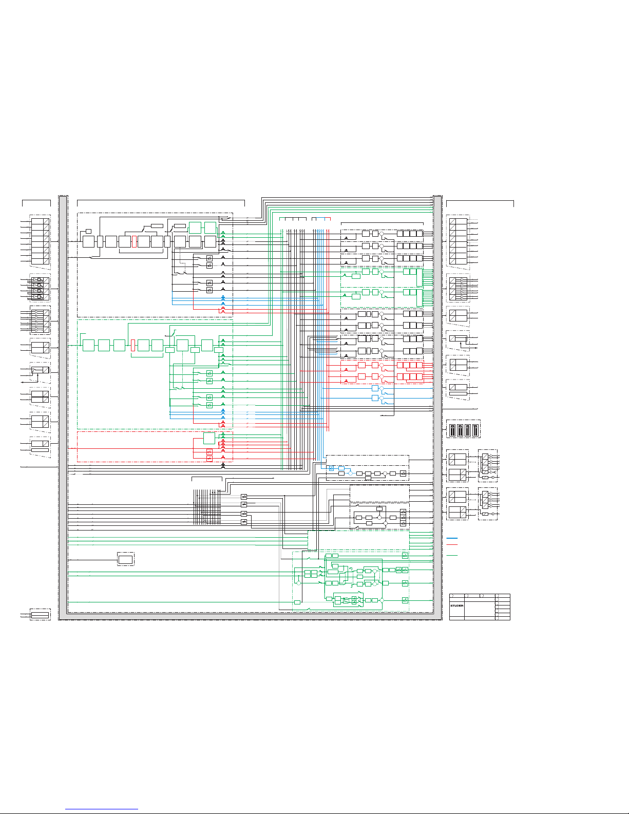
1. Audio Block Diagram, System Wiring
2. Desk Modules
3. DSP Modules
For information on the D21m I/O system please refer to the separate documents BD10.275102
and BD10.275113
Service Instructions
Page 2

Prepared and edited by Copyright by Studer Professional Audio GmbH
Studer Professional Audio GmbH
Technical Documentation Order no. BD10.275124-3 (0311)
Althardstrasse 30
CH-8105 Regensdorf – Switzerland
http://www.studer.ch Subject to change
Studer is a registered trade mark of Studer Professional Audio GmbH, Regensdorf
Page 3

I
For Your Own Safety and to Avoid Invalidation of the Warranty
Please Read This Section Carefully
• Readtheseinstructions.
• Keeptheseinstructions.
• Heedallwarnings.
• Followallinstructions.
• Donotusethisapparatusnearwater.
• Cleanonlywithadrycloth.
• Do notblock any ventilation openings. Installin accordance with the
manufacturer'sinstructions.
• Do notinstall near any heat sources such asradiators, heat registers,
stoves,orotherapparatus(includingampliers)thatproduceheat.
• Donotdefeatthesafetypurposeofapolarisedorgroundingtypeplug.A
polarisedplughastwobladeswithonewiderthantheother.Agrounding
typeplughastwobladesandathirdgroundingprong.Thewidebladeor
thethirdprongareprovidedforyoursafety.Iftheprovidedplugdoesnot
tintoyouroutlet,consultanelectricianforreplacementoftheobsolete
outlet
• Protectthepowercordfrombeingwalkedonorpinchedparticularly
atplugs,conveniencereceptaclesandthepointwheretheyexitfromthe
apparatus.
• Onlyuseattachments/accessoriesspeciedbythemanufacturer.
• Useonlywiththecart,stand,tripod,bracketortable speciedbythe
manufacturer,orsoldwiththeapparatus.Whenacartisused,usecautionwhenmovingthecart/apparatuscombinationtoavoidinjuryfrom
tip-over.
• Referallservicing toqualiedservicepersonnel. Servicingisrequired
whentheapparatushasbeendamagedinanyway,suchaspower-supply
cordorplugisdamaged,liquidhasbeenspilledorobjectsfallenintothe
apparatus,theapparatushasbeenexposedtorainormoisture,doesnot
operatenormally,orhasbeendropped.
Note: Itis recommended that all maintenanceand service on the product
shouldbecarriedoutbyStuderoritsauthorisedagents.Studercannot
acceptanyliabilitywhatsoeverforanylossordamagecausedbyservice,
maintenanceorrepairbyunauthorisedpersonnel.
• WARNING:Toreducetheriskofreorelectricshock,donotexposethis
apparatustorainormoisture.Donotexposetheapparatustodripping
orsplashinganddo notplaceobjectslledwithliquids,suchasvases,
ontheapparatus.
• Nonakedamesources,suchaslightedcandles,shouldbeplacedonthe
apparatus.
• Ventilationshouldnotbeimpededbycoveringtheventilationopenings
withitemssuchasnewspapers,tablecloths,curtainsetc.
Warning: Donotusethisapparatusinverydustyatmospheres,orinatmospheres
containingammablegasesorchemicals.
• THISAPPARATUSMUSTBE EARTHED. Under no circumstances
shouldthesafetyearthbedisconnectedfromthemainslead.
Safety Information
Page 4
II
• Themainssupplydisconnectdeviceisthemains plug. Itmustremain
accessiblesoastobereadilyoperablewhentheapparatusisinuse.
• Ifanypartofthemainscordsetisdamaged,thecompletecordsetshould
bereplaced.Thefollowinginformationisforreferenceonly.Thewires
inthemainsleadarecolouredinaccordancewiththefollowingcode:
• ProtectiveEarth(Ground):Green/Yellow (US:Green or Green/
Yellow)
• Neutral:Blue(US:White)
• Live(Hot):Brown(US:Black)
Asthecoloursofthewiresinthemainsleadmaynotcorrespondwith
thecolouredmarkingsidentifyingtheterminalsinyourplug, proceed
asfollows:
• ThewirewhichiscolouredGreenandYellowmustbeconnectedto
theterminalintheplugwhichismarkedwiththeletterEorbythe
earthsymbol.
• ThewirewhichiscolouredBluemustbeconnectedtotheterminalin
theplugwhichismarkedwiththeletterN
• ThewirewhichiscolouredBrownmustbeconnectedtotheterminal
intheplugwhichismarkedwiththeletterL
Ensurethatthesecolourcodesarefollowedcarefullyintheeventofthe
plugbeingchanged
• This unit iscapable of operating over arange of mains voltages, as
markedontherearpanel.
Note: This equipment has been tested and found to comply with the limits for a
Class A digital device, pursuant to Part 15 of the FCC Rules. These limits are
designed to provide reasonable protection against harmful interference when
the equipment is operated in a commercial environment. This equipment generates, uses and can radiate radio frequency energy and, if not installed and
used in accordance with the instruction manual, may cause harmful interference to radio communications. Operation of this equipment in a residential
area is likely to cause harmful interference in which case the user will be
required to correct the interference at his own expense.
This Class A digital apparatus meets the requirements of the Canadian Inter-
ference-Causing Equipment Regulations.
Cet appareil numérique de la Classe A respecte toutes les exigences du Règle-
ment sur le matériel brouilleur du Canada.
WorkingSafelyWithSound Although your new console will not make any noise until you feed it signals,
it has the capability to produce sounds that, when monitored through a monitor system or headphones, can damage hearing over time.The table below is
taken from the Occupational Safety & Health Administration directive on
occupational noise exposure (1926.52):
PermissibleNoiseExposure:
Duration per day [h] Sound level [dBA, slow response]
8 90
6 92
4 95
3 97
2 100
1.5 102
1 105
0.5 110
<0.25 115
!
Safety Information
Page 5
III
Conforming to this directive will minimise the risk of hearing damage caused
by long listening periods. A simple rule to follow is: The longer you listen, the
lower the average volume should be. Please take care when working with your
audio system – if you are manipulating controls which you don’t understand
(which we all do when we are learning), make sure your monitoring level is
turned down. Remember that your ears are the most important tool of your
trade. Look after them, and they will look after you. Most importantly: Don’t
be afraid to experiment to nd out how each parameter affects the sound;
this will extend your creativity and help you to get the best results.
A1 Safety Symbol Guide
For your own safety and to avoid invalidation of the warranty, all text marked
with these symbols should be read carefully.
To reduce the risk of electric shock, do not remove covers. No user-service-
able parts inside. Refer servicing to qualied service personnel (i.e., persons
having appropriate technical training and experience necessary to be aware
of hazards to which they are exposed in performing a repair action, and of
measures to minimize the danger of themselves).
The lightning ash with arrowhead symbol is intended to alert the user to the
presence of un-insulated “dangerous voltage” within the product’s enclosure
that may be of sufcient magnitude to constitute a risk of electric shock to
persons.
The exclamation point within an equilateral triangle is intended to alert the
user to the presence of important operating and maintenance (servicing)
instructions in the literature accompanying the appliance.
Headphones safety warnings contain important information and useful tips
on headphone outputs and monitoring levels.
Assemblies or sub-assemblies of this product can contain opto-electronic
devices. As long as these devices comply with Class I of laser or LED products according to EN 60825-1:1994, they will not be expressly marked on
the product. If a special design should be covered by a higher class of this
standard, the device concerned will be marked directly on the assembly or
sub-assembly in accordance with the above standard.
A2 First Aid
InCaseofElectricShock: Separate the person as quickly as possible from the electric power source:
• By switching the equipment off,
• By unplugging or disconnecting the mains cable, or
• By pushing the person away from the power source, using dry insulating
material (such as wood or plastic).
• After having suffered an electric shock, always consult a doctor.
Warning! Do not touch the person or his clothing before the power is turned off,
otherwise you stand the risk of suffering an electric shock as well!
IfthePersonisUnconscious: • Lay the person down
• Turn him to one side
• Check the pulse
• Reanimate the person if respiration is poor
• Call for a doctor immed iately.
CAUTION
RISK OF ELECTRIC SHOCK
DO NOT OPEN
ACHTUNG
GEFAHR: ELEKTRISCHER SCHLAG
NICHT ÖFFNEN
ATTENTION
RISQUE DE CHOC ELECTRIQUE
NE PAS OUVRIR
!
CLASS 1
LASER PRODUCT
CLASS 1
LED PRODUCT
!
Safety Information
Page 6

IV
B General Installation Instructions
Please consider besides these general instructions also any product-specic
instructions in the “Installation” chapter of this manual.
B1 Unpacking
Check the equipment for any transport damage. If the unit is mechanically
damaged, if liquids have been spilled or if objects have fallen into the unit,
it must not be connected to the AC power outlet, or it must be immediately
disconnected by unplugging the power cable. Repair must only be performed
by trained personnel in accordance with the applicable regulations.
B2 Installation Site
Install the unit in a place where the following conditions are met:
• The temperature and the relative humidity of the environment must be
within the specied limits during operation of the unit. Relevant values
are the ones at the air inlets of the unit (refer to Appendix 1).
• Condensation must be avoided. If the unit is installed in a location with
large variation of ambient temperature (e.g. in an OB-van), appropriate
precautions must be taken before and after operation (refer to Appendix
1).
• Unobstructed air ow is essential for proper operation. Air vents of the
unit are a functional part of the design and must not be blocked in any
way during operation (e.g. by objects placed upon them, placement of the
unit on a soft surface, or installation of the unit within a rack or piece of
furniture).
• The unit must not be heated up by external sources of heat radiation (sunlight, spotlights).
B3 Earthing and Power Supply
Earthing of units with mains supply (class I equipment) is performed via
the protective earth (PE) conductor integrated in the mains cable. Units with
battery operation (< 60 V, class III equipment) must be earthed separately.
Earthing the unit is one of the measures for protection against electrical shock
hazard (dangerous body currents). Hazardous voltage may not only be caused
by a defective power supply insulation, but may also be introduced by the
connected audio or control cables.
If the unit is installed with one or several external connections, its earthing
must be provided during operation as well as while the unit is not operated.
If the earthing connection can be interrupted, for example, by unplugging
the mains plug of an external power supply unit, an additional, permanent
earthing connection must be installed using the provided earth terminal.
Avoid ground loops (hum loops) by keeping the loop surface as small as
possible (by consequently guiding the earth conductors in a narrow, parallel
way), and reduce the noise current owing through the loop by inserting an
additional impedance (common-mode choke).
Installation
Page 7

V
Installation / EMC
ClassIEquipment(MainsOperation)
Should the equipment be delivered without a matching mains cable, the
latter has to be prepared by a trained person using the attached female plug
(IEC 320 / C13 or IEC 320 / C19) with respect to the applicable regulations
in your country.
Before connecting the equipment to the AC power outlet, check that the local
line voltage matches the equipment rating (voltage, frequency) within the
ad missible tolerance. The equipment fuses must be rated in accordance with
the specications on the equipment.
Equipment supplied with a 3-pole appliance inlet (protection conforming to
class I equip ment) must be connect ed to a 3-pole AC power outlet in such a
way that the equipment ca binet is connected to the protective earth.
For information on mains cable strain relief, please refer to Appendix 2.
Female Plugs (IEC320), Front-Side View:
European Standard
(CENELEC)
North American Standard
(NAS)
Brown
L (Live)
Black
Blue
N (Neutral)
White
Green/Yellow
PE (Protective Earth)
Green (or Green/Yellow)
ClassIIIEquipment(BatteryOperationupto60VDC)
Equipment of this protection class must be earthed using the provided earth
terminal if one or more external signals are connected to the unit (see explanation at the beginning of this paragraph).
B4 Electromagnetic Compatibility (EMC)
The unit conforms to the protection requirements relevant to electromagnetic
phenomena that are listed in guidelines 89/336/EC and FCC, part 15.
• The electromagnetic interference generated by the unit is limited in such
a way that other equipment and systems can be operated normally.
• The unit is adequately protected against electromagnetic interference so
that it can operate properly.
The unit has been tested and conforms to the EMC standards of the speci-
ed electromagnetic environment, as listed in the following declaration.
The limits of these standards ensure protection of the environment and corresponding noise immunity of the equipment with appropriate probability.
However, a professional installation and integration within the system are
imperative prerequisites for operation without EMC problems.
For this purpose, the following measures must be followed:
• Install the equipment in accordance with the operating instructions. Use
the supplied accessories.
• In the system and in the vicinity where the equipment is installed, use only
components (systems, equipment) that also fulll the EMC standards for
the given environment.
PE
LN
IEC 320 / C19IEC 320 / C13
PE
LN
Page 8

VI
• Use a system grounding concept that satises the safety requirements
(class I equipment must be connected with a protective ground conductor) and that also takes into consideration the EMC require ments. When
deciding between radial, surface, or combined grounding, the advantages
and disadvantages should be carefully evaluated in each case.
• Use shielded cables where shielding is specied. The connection of the
shield to the corresponding connector terminal or housing should have a
large surface and be corrosion-proof. Please note that a cable shield connected only single-ended can act as a transmitting or receiving antenna
within the corresponding frequency range.
• Avoid ground loops or reduce their adverse effects by keeping the loop surface as small as possible, and reduce the noise current owing through the
loop by inserting an additional impedance (e.g. common-mode choke).
• Reduce electrostatic discharge (ESD) of persons by installing an appropriate oor covering (e.g. a carpet with permanent electrostatic laments) and
by keeping the relative humidity above 30%. Further measures (e.g. con-
ducting oor) are usually unnecessary and only effective if used together
with corresponding personal equipment.
• When using equipment with touch-sensitive operator controls, please take
care that the surrounding building structure allows for sufcient capacitive
coupling of the operator. This coupling can be improved by an additional,
conducting surface in the operator’s area, connected to the equipment
housing (e.g. metal foil underneath the oor covering, carpet with conductive backing).
C Maintenance
All air vents and openings for operating elements (faders, rotary knobs) must
be checked on a regular basis, and cleaned in case of dust accumulation. For
cleaning, a soft paint-brush or a vacuum cleaner is recommended.
Cleaning the surfaces of the unit is performed with a soft, dry cloth or a soft
brush.
Persistent contamination can be treated with a cloth that is slightly humidied
with a mild cleaning solution, such as dishwashing detergent.
For cleaning display windows, commercially available computer/TV screen
cleaners are suited. Use only a slightly damp (never wet) cloth.
Never use any solvents for cleaning the exterior of the unit! Liquids must
never be sprayed or poured on directly!
For equipment-specic maintenance information please refer to the corre-
sponding chapter in the operating and service manuals.
D Electrostatic Discharge during Maintenance and Repair
Caution: Observe the precautions for handling devices sensitive to electrostatic dis-
charge!
Many semiconductor components are sensitive to electrostatic discharge
(ESD). The lifespan of assemblies contain ing such components can be drastically reduced by improper handling during maintenance and repair. Please
observe the following rules when handling ESD sensitive components:
• ESD sensitive components should only be stored and transported in the
packing material specically provided for this purpose.
EMC / Maintenance / ESD
Page 9

VII
ESD / Repair
• When performing a repair by replacing complete assemblies, the removed
assembly must be sent back to the supplier in the same packing material
in which the replacement assembly was shipped. If this should not be the
case, any claim for a possible refund will be null and void.
• Unpacked ESD sensitive components should only be handled in ESD
protected areas (EPA, e.g. area for eld service, repair or service bench)
and only be touched by persons wearing a wristlet connected to the ground
potential of the repair or service bench by a series resistor. The equipment
to be repaired or serviced as well as all tools and electrically semi-conduct-
ing work, storage, and oor mats should also be connected to this ground
potential.
• The terminals of ESD sensitive components must not come in uncontrolled
contact with electro statically chargeable or metallic surfaces (voltage
puncture, discharge shock hazard).
• To prevent the components from undened transient stress and possible
damage due to inadmissible voltages or compensation currents, electrical
connections should only be established or separated when the equipment
is switched off and after any capacitor charges have decayed.
E Repair
By removing housing parts or shields, energized parts may be exposed. For
this reason the following precautions must be observed:
• Maintenance may only be performed by trained personnel in accordance
with the applicable regulations.
• The equipment must be switched off and disconnected from the AC power
outlet before any housing parts are removed.
• Even if the equipment is disconnected from the power outlet, parts with
hazardous charges (e.g. capacitors, picture tubes) must not be touched until
they have been properly discharged. Do not touch hot components (power
semi con ductors, heat sinks, etc.) before they have cooled off.
• If maintenance is performed on a unit that is open ed while being switched
on, no un-insulated circuit compon ents and metallic semiconductor housings must be touched, neither with bare hands nor with un- insulated
tools.
Certain components pose additional hazards:
• Explosion hazard from lithium batteries, electrolytic capacitors and power
semiconductors (Observe the component’s polarity. Do not short battery
terminals. Replace batteries only by the same type).
• Implosion hazard from evacuated display units.
• Radiation hazard from laser units (non-ionizing), picture tubes (ioniz-
ing).
• Caustic effect of display units (LCD) and components containing liquid
electrolyte.
Such components should only be handled by trained personnel who are prop-
erly protected (e.g. protection glasses, gloves).
Page 10
VIII
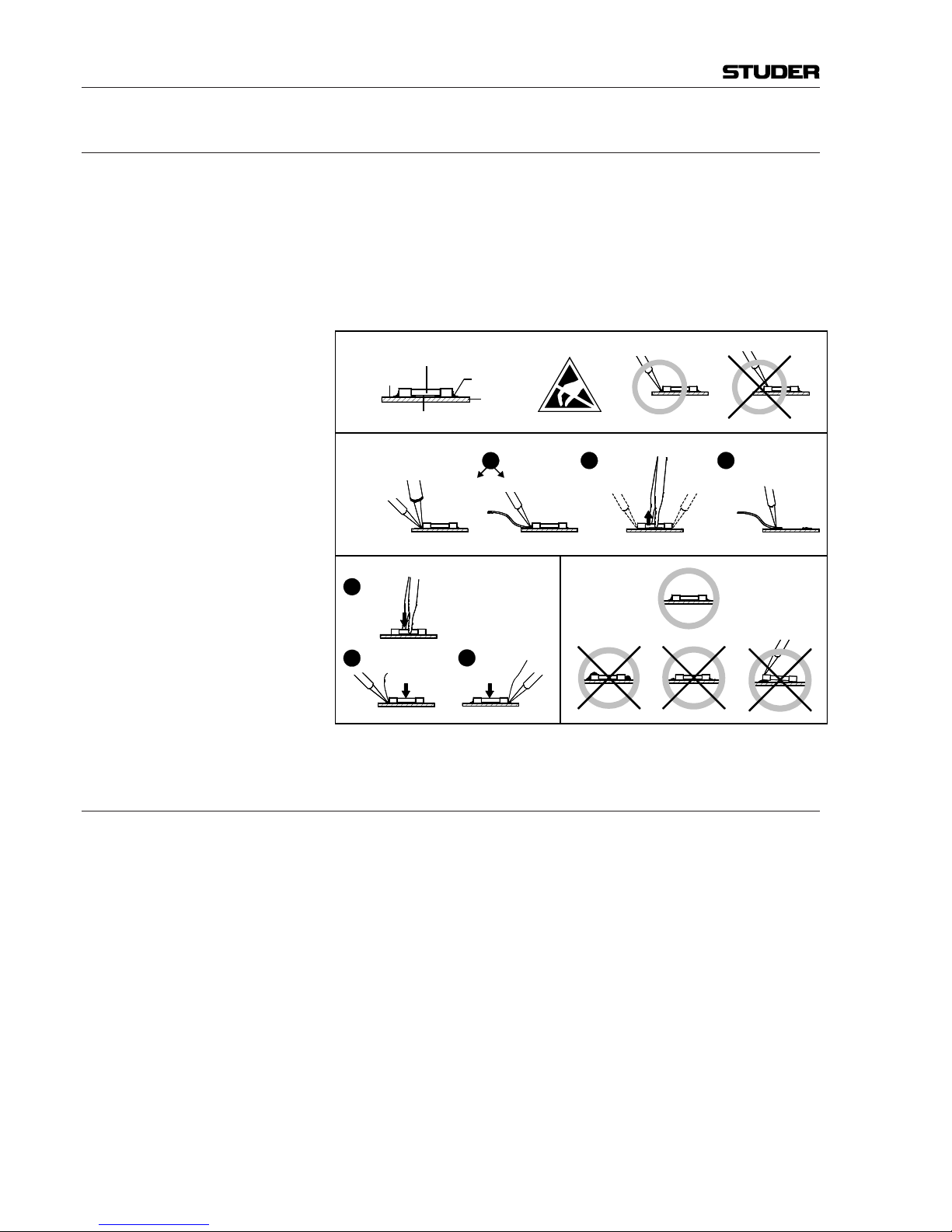
E1 SMD Components
Studer has no commercially available SMD components in stock for ser-
vice purposes. For repair, the corresponding devices have to be purchased
locally. The specications of special components can be found in the service
manual.
SMD components should only be replaced by skilled specialists using appro-
priate tools. No warranty claims will be accepted for circuit boards that have
been damaged. Proper and improper SMD soldering joints are illustrated
below.
F Disposal
PackingMaterials The packing materials have been selected with environmental and disposal
issues in mind. All packing material can be recycled. Recycling packing saves
raw materials and reduces the volume of waste.
If you need to dispose of the transport packing materials, please try to use
recyclable means.
UsedEquipment Used equipment contains valuable raw materials as well as materials that
must be disposed of professionally. Please return your used equipment via an
authorized specialist dealer or via the public waste disposal system, ensuring
any material that can be recycled is.
Please take care that your used equipment cannot be abused. To avoid abuse,
delete sensitive data from any data storage media. After having disconnected
your used equipment from the mains supply, make sure that the mains connector and the mains cable are made useless.
Repair / Disposal
32
Dismounting
Mounting
Examples
Solder
SMD
Component
Copper
Track
Adhesive
Soldering Iron
Desoldering
Iron
Desolder
Wick
Heat and Remove Cleaning
Solder
Ø 0.5...0.8 mm
Heating Time < 3 s per Side
Soldering
Iron
Desolder
Wick
1
3
2
1
PCB
Page 11

IX
G Declarations of Conformity
G1 Class A Equipment - FCC Notice
This equipment has been tested and found to comply with the limits for a
Class A digital device, pursuant to Part 15 of the FCC Rules. These limits
are designed to provide a reasonable protection against harmful interference when the equipment is operated in a commercial environment. This
equipment generates, uses, and can radiate radio frequency energy and, if
not installed and used in accordance with the instruction manual, may cause
harmful interference to radio com munications. Operation of this equipment
in a residential area is likely to cause harmful interference, in which case the
user will be required to correct the interference at his own expense.
This Class A digital apparatus meets the requirements of the Canadian Inter-
ference-Causing Equipment Regulations.
Cet appareil numérique de la Classe A respecte toutes les exigences du Règle-
ment sur le matériel brouilleur du Canada.
Caution: Any changes or modications not expressly approved by the manufacturer
could void the user’s authority to operate the equipment. Also refer to relevant
information in this manual.
G2 CE Declaration of Conformity
We,
StuderProfessionalAudioGmbH,
CH-8105Regensdorf,
declare under our sole responsibility that the product
StuderOnAir3000,DigitalMixingSystem
(startingwithserialno.1001),
to which this declaration relates, according to following regulations of EU
directives and amendments
• Low Voltage (LVD):
73/23/EEC + 93/68/EEC
• Electro magnetic Compatibility (EMC):
89/336/EEC + 92/31/EEC + 93/68/EEC
is in conformity with the following standards or normative documents:
• Safety:
EN 60950:2001 (Class I equipment)
• Safety of laser products:
EN 60825-1:1994 + A11 + A2, EN 60825-2:2000
• EMC:
EN 55103-1/-2:1996, electromagnetic environments E2 and E4.
Regensdorf, April 14, 2005
B. Hochstrasser, President M. Lienert, Manager R&D
Conformity
Page 12

X
Appendix 1: Air Temperature and Humidity
General
Normal operation of the unit or system is warranted under the ambient condi-
tions dened by EN 60721-3-3, set IE32, value 3K3.
This standard consists of an extensive catalogue of parameters, the most
important of which are: ambient temperature +5...+40 °C, relative humidity 5...85% (i.e., no formation of condensation or ice); absolute humidity
1...25 g/m³; rate of temperature change < 0.5 °C/min. These parameters are
dealt with in the following paragraphs.
Under these conditions the unit or system starts and works without any prob-
lem. Beyond these specications, possible problems are described below.
Ambient Temperature
Units and systems by Studer are generally designed for an ambient tempera-
ture range (i.e. temperature of the incoming air) of +5 °C to +40 °C. When
rack mounting the units, the intended air ow and herewith adequate cooling
must be provided. The following facts must be considered:
• The admissible ambient temperature range for operation of the semiconductor components is 0 °C to +70 °C (commercial temperature range for
operation).
• The air ow through the installation must provide that the outgoing air is
always cooler than 70 °C.
• Average heat increase of the cooling air shall be about 20 K, allowing for
an additional maximum 10 K increase at the hot components.
• In order to dissipate 1 kW with this admissible average heat increase, an
air ow of 2.65 m³/min is required.
Example: A rack dissipating P = 800 W requires an air ow of 0.8 * 2.65 m³/min which
corresponds to 2.12 m³/min.
• If the cooling function of the installation must be monitored (e.g. for fan
failure or illumination with spot lamps), the outgoing air temperature must
be measured directly above the modules at several places within the rack.
The trigger temperature of the sensors should be 65 °C to 70 °C.
Frost and Dew
The unsealed system parts (connector areas and semiconductor pins) allow
for a minute formation of ice or frost. However, formation of dew visible to
the naked eye will already lead to malfunctions. In practice, reliable operation can be expected in a temperature range above –15 °C, if the following
general rule is considered for putting the cold system into operation:
If the air within the system is cooled down, the relative humidity rises. If it
reaches 100%, condensation will arise, usually in the boundary layer between
the air and a cooler surface, together with formation of ice or dew at sensitive areas of the system (contacts, IC pins, etc.). Once internal condensation
occurs, trouble-free operation cannot be guaranteed, independent of temperature.
Before putting into operation, the system must be checked for internal for-
mation of condensation or ice. Only with a minute formation of ice, direct
Appendix
Page 13

XI
evaporation (sublimation) may be expected; otherwise the system must be
heated and dried while switched off.
A system without visible internal formation of ice or condensation should be
heated up with its own heat dissipation, as homogeneously (and subsequently
as slow) as possible; the ambient temperature should then always be lower
than the one of the outgoing air.
If it is absolutely necessary to operate the cold system immediately within
warm ambient air, this air must be dehydrated. In such a case, the absolute
humidity must be so low that the relative humidity, related to the coldest
system surface, always remains below 100%.
Ensure that the enclosed air is as dry as possible when powering off (i.e. before
switching off in winter, aerate the room with cold, dry air, and remove humid
objects such as clothes from the room).
These relationships are visible from the following climatogram. For a con-
trolled procedure, thermometer and hygrometer as well as a thermometer
within the system will be required.
Example1: An OB-van having an internal temperature of 20 °C and a relative humidity of
40% is switched off in the evening. If the temperature falls below +5 °C, the
relative humidity will rise to 100% (7 g/m³); dew or ice will be forming.
Example2: An OB-van is heated up in the morning with air of 20 °C and a relative
humidity of 40%. On all parts being cooler than +5 °C, dew or ice will be
forming.
Appendix
Page 14
XII
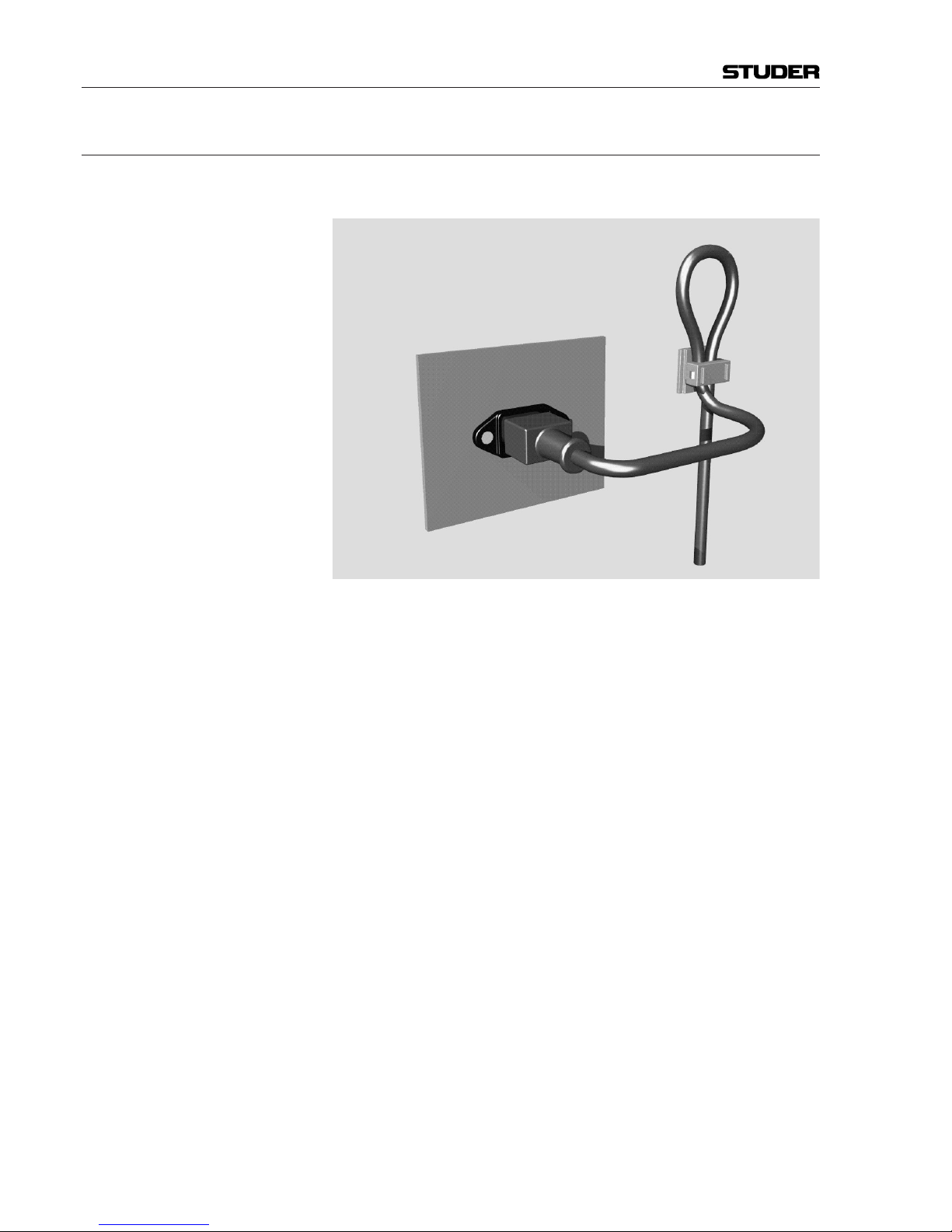
Appendix 2: Mains Connector Strain Relief
For anchoring connectors without a mechanical lock (e.g. IEC mains connec-
tors), we recommend the following arrangement:
Procedure: The cable clamp shipped with your unit is auto-adhesive. For mounting please
follow the rules below:
• The surface to be adhered to must be clean, dry, and free from grease, oil,
or other contaminants. Recommended application temperature range is
+20 °C to +40 °C.
• Remove the plastic protective backing from the rear side of the clamp
and apply it rmly to the surface at the desired position. Allow as much
time as possible for curing. The bond continues to develop for as long as
24 hours.
• For improved stability, the clamp should be xed with a screw. For this
purpose, a self-tapping screw and an M4 bolt and nut are included.
• Place the cable into the clamp as shown in the illustration above and rmly
press down the internal top cover until the cable is xed.
Appendix
Page 15

XIII
Appendix
Appendix 3: Software License
Use of the software is subject to the Studer Professional Audio Software
License Agreement set forth below. Using the software indicates your acceptance of this license agreement. If you do not accept these license terms, you
are not authorized to use this software.
Under the condition and within the scope of the following Terms and Con-
ditions, Studer Professional Audio GmbH (hereinafter “Studer”) grants the
right to use programs developed by Studer as well as those of third parties
which have been installed by Studer on or within its products. References
to the license programs shall be references to the newest release of a license
program installed at the Customer’s site.
Programs Covered by the Agreement
LicenseProgramsofStuder The following Terms and Conditions grant the right to use all programs of
Studer that are part of the System and/or its options at the time of its delivery
to the Customer, as well as the installation software on the original data disk
and the accompanying documentation (“License Material”). In this Agreement the word “Programs” shall have the meaning of programs and data
written in machine code.
Using the software indicates your acceptance of this license agreement. If
you do not accept these license terms, you are not authorized to use this software.
ProgramsofThirdParties Programs of third parties are all programs which constitute part of the System
and/or its options at the time of delivery to the Customer but have not been
developed by Studer. The following conditions are applicable to programs of
third parties:
• The right to use third parties’ programs is governed by the License Agreement attached hereto (if applicable), which is an integral part of this Agreement. The Customer shall sign any and all License Agreements for all
further programs of third parties installed on the system. The Customer
shall be deemed to have received all License Agreements upon delivery
of the system and/or its options.
• Studer shall accept no responsibility or liability for, and gives no warranties (express or implied) as to the programs of third parties. The Customer
waives any and all claims versus Studer for any consequential damages,
which might occur due to defects of these programs.
Right of Use
Principle Studer grants the Customer the non-exclusive right to use the License Ma-
terial in one copy on the system and/or its options as laid down by the Sales
Agreement concluded between the parties and all Terms and Conditions
which shall be deemed to form and be read and construed as part of the
Sales Agreement. This right is assignable according to the “Assignability”
paragraph hereinafter.
CustomizedCongurations The Customer is not entitled to alter or develop further the License Material
except within the expressly permitted conguration possibilities given by the
software installed on the system or elsewhere. All altered programs, includ-
Page 16

XIV
ing but not limited to the products altered within the permitted conguration
possibilities, are covered by this License Agreement.
ReverseEngineering Reverse engineering is only permitted with the express consent of Studer.
The consent of Studer can be obtained but is not limited to the case in which
the interface software can not be provided by Studer. In any case Studer has
to be informed immediately upon complete or partial reverse engineering.
CopyingtheLicenseMaterial The Customer is entitled to make one copy of all or parts of the License
Material as is necessary for the use according to this Agreement, namely for
backup purposes. The Customer shall apply the copyright of Studer found on
the License Material onto all copies made by him. Records shall be kept by
the Customer regarding the amount of copies made and their place of keeping.
The responsibility for the original program and all copies made lies with the
Customer. Studer is entitled to check these records on rst request. Copies
not needed anymore have to be destroyed immediately.
DisclosureofLicenseMaterial The License Material is a business secret of Studer. The Customer shall not
hand out or in any way give access to parts of or the complete License Material
to third parties nor to publish any part of the License Material without prior
written consent of Studer. The Customer shall protect the License Material
and any copies made according to the paragraph above by appropriate defense
measures against unauthorized access. This obligation of non-disclosure is a
perpetual obligation.
Third parties are entitled to have access to the License Material if they use the
License Material at the Customer’s site in compliance with this Agreement.
Under no circumstance are third parties entitled to have access to the instal-
lation software on the original data media. The Customer shall safeguard the
original data media accordingly.
Assignability The rights granted to the Customer according to this License Agreement shall
only be assignable to a third party together with the transfer of the system
and/or its options and after the prior written consent of Studer.
Rights to License Material
With the exception of the right of use granted by this License Agreement all
proprietary rights to the License Material, especially the ownership and the
intellectual property rights (such as but not limited to patents and copyright)
remain with Studer even if alterations, customized changes or amendments
have been made to the License Material.
Studer’s proprietary rights are acknowledged by the Customer. The Customer
shall undertake no infringements and make no claims of any patent, registered
design, copyright, trade mark or trade name, or other intellectual property
right.
Warranty, Disclaimer, and Liability
For all issues not covered herewithin, refer to the “General Terms and Condi-
tions of Sales and Delivery” being part of the sales contract.
Appendix
Page 17
Date printed: 28.02.11
OnAir 3000 Digital Mixing Console
Important
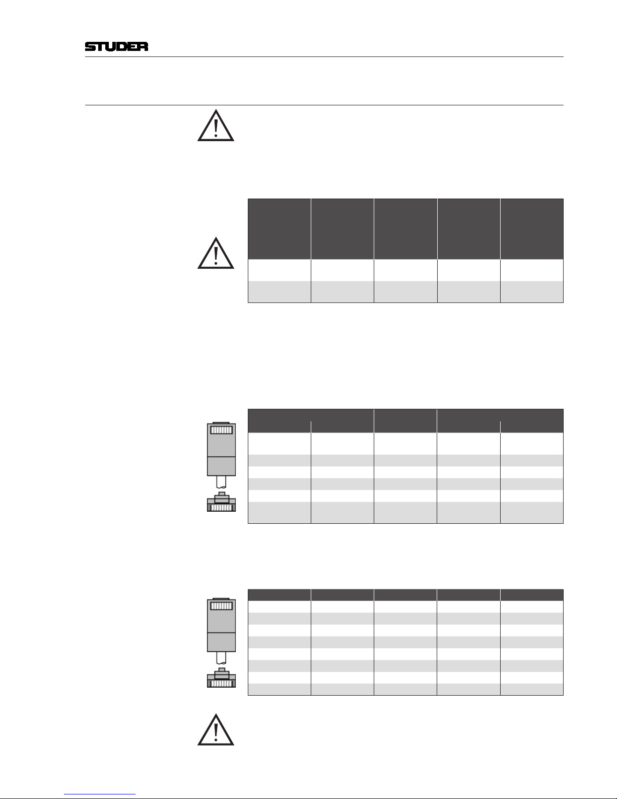
WIRING – IMPORTANT
The OnAir 3000 RS422 and Ethernet wiring must comply with
the following requirements:
Cable Type: Cat 5e, with shielded connectors on both ends
Cable Dimensions
Max. Length
for Screens
Max. Length
for Motor
Fader
Modules
Max. Length
for Other
Modules
Min.
AWG
Min.
Sectional
Area
20 m 30 m 100 m 24 0.21 mm
2
13 m 18 m 60 m 26 0.13 mm
2
Details Cat(egory) 5e Cable is an enhanced version of Cat 5 that adds specifications for far-end crosstalk.
It replaced the specification for Cat 5 with the 2001 introduction of the TIA/
EIA-568-B standard. Cat 5e cable performance characteristics and test methods are defined in TIA/EIA-568-B.2-2001.
RS422 Cables (Cat 5e) (both ends with shielded connectors) from the distribution box to all kinds
of desk and screen modules.
Distribution Box
Wire Color
Desk Module
Signal Pin Pin Signal
+24 V *
1
2
wht/org
org
1
2
+24 V *
RX+ 3 wht/grn 3 TX+
TX+ 4 blu 4 RX+
TX– 5 wht/blu 5 RX–
RX– 6 grn 6 TX–
Gnd *
7
8
wht/brn
brn
7
8
Gnd *
Ethernet Cables (Cat 5e) (both ends with shielded connectors) for use between the SCore host card
and the main screen module (via hub/switch), as well as for HD Link, D21m
control, and networking connections. Since modern hubs and switches have
auto polarity selection, straight-through cables may be used in any case.
Signal Pin
Wire Color
Pin Signal
TX+ 1 wht/org 1 TX+
TX– 2 org 2 TX–
RX+ 3 wht/grn 3 RX+
4 blu 4
5 wht/blu 5
RX– 6 grn 6 RX–
7 wht/brn 7
8 brn 8
* Caution Connectors are identical on the RS422 and the Ethernet cables.
Make sure not to mix them up since the RS422 sockets carry
DC supply voltage!
Top (tab
down):
18
18
Front:
Top (tab
down):
18
18
Front:
Order no. BD10.275230
Page 18

Date printed: 28.02.11
OnAir 3000 Digital Mixing Console
Important
USB MEMORY DEVICE – IMPORTANT
A memory device connected to an USB socket must not be
unplugged while its indicator LED is illuminated or ashing.
Page 19
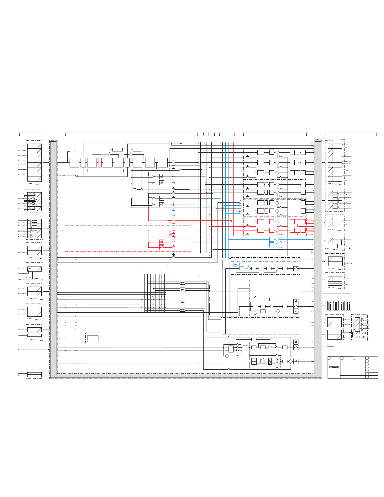
1-1
Date printed: 28.02.11
AUX
MAIN
Σ MASTER / SEND / GROUP AND MONITORING
Master AUX Listen N-X GRPMPX
REC MASTER
PFL
AUX 1
AUX 4
PFL
PFL
PRG B MASTER
PRG A MASTER
PFL
PFL
ΣN-X 1
N-X
ΣN-X 16
N-X
PFL
CUE
CUE ST1
CUE
CUE ST1
MPX
MPX
MPX
MPX
FADER
FADER
PFL
ST1 TB RET
ST3 TB RET
ST2 TB RET
CR TB RET
SP SRC
CUT
MONO
same as PFL CR
TB to Master/Send/Group
TB to Master/Send/Group
GRP 1
GRP 8
FADER
FADER
PFL
PFL
MPX
CUT
TB
DIM
TB
DIM
TB
DIM
TB
TB
TB
TALK
same as CONTROL ROOM
ST1 ADD SRC
TB to ST1
TB to ST1
TB to CR
TALK
ST2 SRC
TB to ST2
TB to ST3
TB to ST2 HP
TB to ST3 HP
ST3 SRC
ST1 SRC
same as STUDIO 2
SP SRC
SP SRC
/ MON
STUDIO 3
STUDIO 2
CONTROL ROOM
(Monitoring Mode I)
NONE
SPLIT
CR ADD MODE
MONO MONO
MONO
MONO
MONO
MIX
DJ HP MODE
STUDIO 1
with PFL SP
TALK
CR ADD SRC
CR SP SRC
MON to L
ST1 SP SRC
TALK
TB to CR
TB to CR HP
TB to ST1 HP
CR SRC
OUTPUTS
INS
L (M)
TB
DIM
SLATE
TB
DIM
TALK
TALK
TALK
D
D
SFC
D
D
D
D
D
D
D
D
SFC
D
D
D
D
D
D
AES MODULE (OUT)
d
d
d
d
d
d
d
d
TB
DIM
SLATE
TB
DIM
sync
sync
SLATE
LIM M/S
R (M)
M
INS
L (M)
LIM M/S
R (M)
M
INS
L (M)
LIM M/S
R (M)
M
L (M)
M/S
R (M)
M
L (M)
FADER
INS SEND
ONFADER
FADER
FADER
CHANNEL OUT
DIRECT OUT PP
DIRECT OUT AP
TB
DIM
TALK
LINE OUT MODULE
a
a
D
A
a
a
D
A
a
a
D
A
a
a
D
A
Audition
TB
DIM
TB
DIM
FADER ON
ON
ON
GUI Meter
ADAT / TDIF (OUT)
D
D
d
8/16
35
TB
DIM
TALK
TB
DIM
TB
DIM
TB
DIM
TALK
TALK
TALK
L (M)
M/S
R (M)
M
L (M)
M/S
R (M)
M
INS
EQ 4B
COMP
DUCK
EQ 4B
COMP
DUCK
Side Chain
Side Chain
MPX
MPX Studio 1
M/S
R (M)
M
L (M)
M/S
R (M)
M
L (M)
M/S
R (M)
M
PFL CR
PFL STUDIO 1
TB to EXT
TB to EXT1-4 [1-16]
CR SP
ST1 SP
#
ST2 MON LSP
ST3 GUEST HP
ST2 DJ HP
ST3 MON LSP
ST3 DJ HP
PFL ST1
D
D
MADI (OUT)
D
D
Control
DIMCUT
DIM
CUT DIM
PFL CR
SDI SD / HD / 3G (OUT)
D
D
D
D
HD LINK (OUT)
INS
ST2 GUEST HP
ST1 MON LSP
ST1 DJ HP
ST1 GUEST HP
CR MON LSP
CR DJ HP
CR GUEST HP
ADAT
D
D
D
D
D
D
D
D
0
18.02.02 HB
0.5
07.02.03 HB
0.7
12.02.05 HB
0.8
Regensdorf
Switzerland
BLOCK DIAGRAM
AUDIO
Software V3.2
19.04.02 HB
0.81
16.08.05 HB
0.82
21.07.06 SoG
OnAir 3000
0.83
4.12.06 SoG
0.9
16.07.07 SoG
1.0
27.06.08 SoG
1.1
15.03.10 SoG
Configurations C3...C6
64
d
d
64
ETHERSOUND (OUT)
D
D
64
d
d
8
d
8
CR/ST1 MONITOR
D
A
DJ HP
D
A
D
A
DA
GUEST HP
MON LSP
DA
8
8
TB MIC
SP
d
8
d
8
d
8/16
d
96
MON
ST1 SP SRC
CR SP SRC
PRG A
PRG B
REC
AUX 1
AUX 4
PFL
PFL ST1
AUDITION
N-X 1
N-X 16
MPX 1
MPX 16
MPX Listen
MPX Listen
ST1
GRP 1
GRP 8
4 [16]
GPOUT
8
INPUTS
D
D
SFC
AES MODULE (IN)
D
D
SFC
D
D
SFC
D
D
SFC
D
D
SFC
D
D
SFC
D
D
SFC
D
D
SFC
d
d
d
d
d
d
d
d
GPIN
GPIO
16
A
D
MIC MODULE
A
D
A
D
A
D
a
a
a
a
A
D
LINE IN MODULE
A
D
A
D
A
D
a
a
a
a
a
a
a
a
#
ADAT / TDIF (IN)
D
D
8/16
d
D
D
8/16
d
GPOUT
16
GPIN
8
MADI (IN)
D
D
64
d
64
d
Control
AUX
SDI SD / HD / 3G (IN)
D
D
8
d
D
D
8
d
Dolby E (IN)
D
D
8/16
d
D
D
d
8/16
ETHERSOUND (IN)
D
D
64
d
MAIN
d
96
HD LINK (IN)
STEREO INPUT
CHANNEL 1...n
EXT PFL 1
n = max. 24 (for Configurations C3 and C5)
n = max. 48 (for Configurations C4 and C6)
EXT PFL 2
CUE
CUE ST1
INPUT CHANNELS
PHASE
STEREO
CAL
DE-ESSER
EQ
4-band
INS RET
CH INP
N-X
GR METER
DYNDe-S
AP
PP
OVL
DYNAMICS
INS
AP
PROCESSING
FADER BALANCE
CHANNEL
ON/OFF
PRG A
PRG B
AUDITION
AUX 1
AUX 4
PFL
CH
active
AF
PF
PF
AF
AF
PF
CH METER
CUE
PFL
REC
REC PF
N-X 1
N-X 16
AF
PF
PF
AF
PP
AP
TB
35
STUDIO 1 SOURCE
CR SOURCE
STUDIO 3 SOURCE
STUDIO 2 SOURCE
TB from CR
TB from STUDIO 1
TB from STUDIO 2
TB from EXT
TB from EXT1-4 [1-16]
TB from STUDIO 3
4
4 [16]
4 [16]
4 [16]
4
4
TEST GEN.
SINE WAVE
WHITE NOISE
PINK NOISE
CR ADD SOURCE
STUDIO 1 ADD SOURCE
CR SP SOURCE
STUDIO 1 SP SOURCE
4
4
4
TB to CR
TB to CR HP
TB to ST1
TB to ST1 HP
TB to ST2
TB to ST2 HP
TB to ST3
TB to ST3 HP
TB to EXT
TB to EXT1
TB to EXT16
TB to INT1
TB to INT31
INS
PP
MPX 1
MPX 16
MPX Listen
PRG A
GRP 8
GRP 1
PRG B
REC
N-X 1
N-X 16
GRP 1..8 (for Configurations C5 and C6)
GRP
HP
LP
CUT
TB
CUT
TB
CUT
TB
DIM
TB
DIM
TB
CUT
Numbers in square brackets are valid for
Configurations C5 and C6 only
[xx]
MPX Option (Configurations C5 and C6 only)
Group and High-Pass/Low-Pass Filter Option
(Configurations C5 and C6 only)
+
+
+
+
+
+
+
+
+
+
+
+
+
+
+
+
+
+
Page 20
1-2
Date printed: 28.02.11
+
+
+
+
+
+
+
+
+
+
+
+
+
+
+
+
MPX Option
Group and High-/Low-Pass
Filter Option
Numbers in square brackets are
valid for Config C109 only
[xx]
For CR and Studio1 Monitoring
without 5.1 option refer to the
C3...C6 block diagram
*
*
*
Σ
MASTER/SEND/GROUP AND MONITORING
Master AUX Listen N-X GRPMPX
ST1 TB RET
SP SRC
CUT
MPX VOL
MONO
same as PFL CR
TB to Master/Send/Group
MPX
CUT
TB
DIM
CR TB RET
ST2 TB RET
ST3 TB RET
TALK
TALK
ST2 SRC
TB to ST2
TB to ST3
TB to ST3 HP
ST3 SRC
same as STUDIO 2
STUDIO 3
OUTPUTS
D
D
SFC
D
D
D
D
D
D
D
D
SFC
D
D
D
D
D
D
AES MODULE (OUT)
d
d
d
d
d
d
d
d
sync
sync
INS SEND
CHANNEL OUT
DIRECT OUT PP
DIRECT OUT AP
LINE OUT MODULE
a
a
D
A
a
a
D
A
a
a
D
A
a
a
D
A
GUI Meter
ADAT / TDIF (OUT)
D
D
d
8/16
PFL CR
PFL STUDIO 1
TB to EXT
TB to EXT1-16 [48]
CR SP
ST1 SP
#
ST2 LSP
ST3 GUEST HP
ST3 LSP
ST3 DJ HP
D
D
CUT DIM
ST2 GUEST HP
ADAT
D
D
D
D
D
D
D
D
0
18.02.02 HB
0.5
07.02.03 HB
0.7
12.02.05 HB
0.8
Regensdorf
Switzerland
BLOCK DIAGRAM
AUDIO
Software V3.2
19.04.02 HB
0.81
16.08.05 HB
0.82
21.07.06 SoG
OnAir 3000
0.83
4.12.06 SoG
0.9
16.07.07 SoG
1.0
27.6.08 SoG
1.1
15.3.10 SoG
Configurations C7 / C8 / C108 / C109
d
8
d
8
CR / ST1 MONITOR
D
A
DJ HP
D
A
D
A
DA
GUEST HP
MON LSP
(or NF LSP)
DA
8
8
TB MIC
SP
ADAT
D
D
D
D
D
D
D
D
d
8
d
8
ST2 / ST3 MONITOR
D
A
DJ HP
D
A
D
A
GUEST HP
MON LSP
DA
8
8
TB MIC
d
8/16
PRG A
PRG B
REC
AUX 1
AUX 4
PFL
PFL ST1
AUDITION
N-X 1
N-X 16 [48]
MPX 1
MPX 16
MPX Listen
MPX Listen
ST1
GRP 1
GRP 8
TB
DIM
TB
DIM
TB to ST1
TB to ST2 HP
STUDIO 2
TALK
TALK
TB to CR
TB to CR HP
TB to ST1 HP
ST2 DJ HP
DIM
ST1 DJ HP
ST1 GUEST HP
CR NF LSP
ST1 NF LSP
CR DJ HP
CR ENC RET
ST1 ENC RET
CR GUEST HP
ST1 SP SRC
CR SP SRC
AUX 1
AUX 4
PFL
PFL
N-X
N-X
PFL
CUE
CUE ST1
CUE
CUE ST1
FADER
FADER
PFL
TB to Master/Send/Group
TB
DIM
TALK
L (M)
M/S
R (M)
M
L (M)
ONFADER
TB
DIM
TALK
TALK
Audition
TB
DIM
TB
DIM
TALK
FADER ON
ON
ON
35 [67]
M/S
R (M)
M
L (M)
M/S
R (M)
M
L (M)
M/S
R (M)
M
PFL ST1
PFL CR
REC MASTER
PFL
PFL
PFL
PRG B MASTER
INS
L (M)
TB
DIM
TB
DIM
LIM DLY
DLY
DLY
DLY
DLY
DLY
DLY
DLY
DLY
DLY
DLY
M/S
R (M)
M
INS
L (M)
LIM M/S
R (M)
M
INS
L (M)
LIM M/S
R (M)
M
FADER
FADER
FADER
TB
DIM
PFL
PFL
L
SLATE
R
M
L
R
M
LIM
LIM
LIM
LIM
Side Chain
MPX
MPX
GRP 1
GRP 8
FADER
FADER
PFL
PFL
TB
DIM
TALK
TB
DIM
TALK
TB
DIM
TALK
TB
DIM
TALK
L (M)
M/S
R (M)
M
L (M)
M/S
R (M)
M
INS
EQ 4B
COMP
DUCK
EQ 4B
COMP
DUCK
Side Chain
MPX
MPX Studio 1
INS
AUX
MAIN
MADI (OUT)
D
D
Control
SDI SD / HD / 3G (OUT)
D
D
D
D
HD LINK (OUT)
64
d
d
64
ETHERSOUND (OUT)
D
D
64
d
d
8
d
8
d
96
GPOUT
8
D
D
SFC
AES MODULE (IN)
D
D
SFC
D
D
SFC
D
D
SFC
D
D
SFC
D
D
SFC
D
D
SFC
D
D
SFC
d
d
d
d
d
d
d
d
GPIN
GPIO
16
A
D
MIC MODULE
A
D
A
D
A
D
a
a
a
a
A
D
LINE IN MODULE
A
D
A
D
A
D
a
a
a
a
a
a
a
a
#
ADAT / TDIF (IN)
D
D
8/16
d
D
D
8/16
d
GPOUT
16
STEREO INPUT
CHANNEL 1...n
EXT PFL 1
EXT PFL 2
CUE
CUE ST1
INPUT CHANNELS
PHASE
STEREO
CAL
DE-ESSER
EQ
4-band
INS RET
CH INP
N-X
N-X
GR METER
DYN
De-S
INS
PP
AP
PP
OVL
DYNAMICS
INS
AP
PROCESSING
FADER
CHANNEL
ON/OFF
PAN /
BALANCE
PRG A
PRG B
AUDITION
AUX 1
AUX 4
PFL
CH
active
AF
PF
PF
AF
AF
PF
CH METER
CUE
PFL
REC
REC PF
N-X 1
N-X 16 [48]
AF
PF
PF
AF
PP
DIR OUT
AP
n + 4m = max. 24 for C7 only
n + 4m = max. 48 for C8, C108, C109
TB
35 [67]
16 [48]
STUDIO 3 SOURCE
STUDIO 2 SOURCE
TB from CR
TB from STUDIO 1
TB from STUDIO 2
TB from STUDIO 3
16 [48]
4
4
4
TEST GEN.
SINE WAVE
WHITE NOISE
PINK NOISE
4
16 [48]
4
4
TB to CR
TB to CR HP
TB to ST1
TB to ST1 HP
TB to ST2
TB to ST2 HP
TB to ST3
TB to ST3 HP
TB to EXT
TB to EXT1
TB to EXT16 [48]
TB to INT1
TB to INT33 [65]
INPUTS
CHANNEL
ON/OFF
5.1
PAN
5.1 A
5.1 B
6
6
DELAY
STUDIO 1 SOURCE
CR SOURCE
6
6
6
6
6
6
CR ADD SOURCE
STUDIO 1 ADD SOURCE
CR SP SOURCE
STUDIO 1 SP SOURCE
5.1 A
5.1 B
6
6
GPIN
8
MADI (IN)
D
D
64
d
64
d
Control
AUX
D
D
8
d
D
D
8
d
Dolby E (IN)
D
D
8/16
d
D
D
d
8/16
ETHERSOUND (IN)
D
D
64
d
MAIN
d
96
HD LINK (IN)
TB from EXT
TB from EXT1-16 [48]
ΣN-X 1
ΣN-X 16 [48]
GRP
GRP 1..8
HP
LP
PRG A
GRP 8
GRP 1
PRG B
REC
N-X 1
N-X 16 [48]
MPX 1
MPX 16
MPX Listen
SLATE
SLATE
SLATE
SLATE
PRG A MASTER
TB CUT
TB
DIM
CUT
TB
CUT
SDI SD / HD / 3G (IN)
+
+
+
+
+
5.1-Channel Option
5.1
6
6
6
6
6
6
6
5.1 CHANNEL OUT
5.1 DIRECT OUT PP
5.1 DIRECT OUT AP
5.1 A
5.1B
66
same as CONTROL ROOM
ST1 ADD SRC
ST1 SRC
CONTROL ROOM
NONE
SPLIT
CR ADD
MODE
5.1 /
STEREO
5.1 /
STEREO
5.1 /
STEREO
MIX
STUDIO 1
CR ADD SRC
CR SP SRC
ST1 SP SRC
CR SRC
CR MON LSP
CR ENC SEND
ST1 MON LSP
ST1 ENC SEND
5.1 /
STEREO
5.1 B
5.1 A
TB
DIM
LIM
M /
S /
5.1
LIMFADER
FADER
5.1 L
5.1 R
5.1 C
5.1 Lfe
5.1 Ls
5.1 Rs
M /
S /
5.1
5.1 L
5.1 R
5.1 C
5.1 Lfe
5.1 Ls
5.1 Rs
TB
DIM
5.1 /
STEREO
5.1 /
STEREO
MONO
MONO
SP SRC
CR MON/
LSP SRC
5.1 /
STEREO
STEREO
STEREO
ENC
ENC
DIR
MONO
5.1 /
STEREO
MONO
MONO
DJ HP MODE
MON LSP SEL
with
PFL SP
MON to L
CR MON
NF LSP
SEL
MONO
6 x SP
ON
6 x SP
CAL
5.1 /
STEREO
MONO
PRG A
PRG B
AUDITION
AUX 1
AUX 4
PFL
CH
active
AF
PF
PF
AF
CUE
PFL
REC
REC PF
N-X 1
N-X 16 [48]
AF
PF
PF
AF
DIR OUT PP
5.1-CH INPUT
CHANNEL 1...m
n + 4m = max. 24 for C7 only
n + 4m = max. 48 for C8, C108, C109
6 x 6
INPUT
ROUTING
6 x 6
Individual
CAL
EQ
4-band
5.1 /
STEREO
5.1 /
STEREO
5.1 /
STEREO
5.1 INP 6
6
6
6
6
6
GR METER
OVL
(Max.
of 6)
DYNAMICSDELAY
PROCESSING
6 x FADER
CHANNEL
ON/OFF
5.1 A
5.1 B
AF
PF
CH MTR (Max. of 6)
DIR OUT AP
CH OUT
HP
LP
GRP 8
GRP 1
MPX 1
MPX 16
MPX Listen
5.1
PAN
CUT
CUT
DIM
DIM
TB
DIM
TB
DIM
TB
CUT
MONO
MONO
Page 21

1-3
Date printed: 28.02.11
Page 22

1-4
Date printed: 28.02.11
Page 23

2-1
Date printed: 28.02.11
Desk Modules Remarks
A
ssembly No.
Main Screen Module
A
943.041000
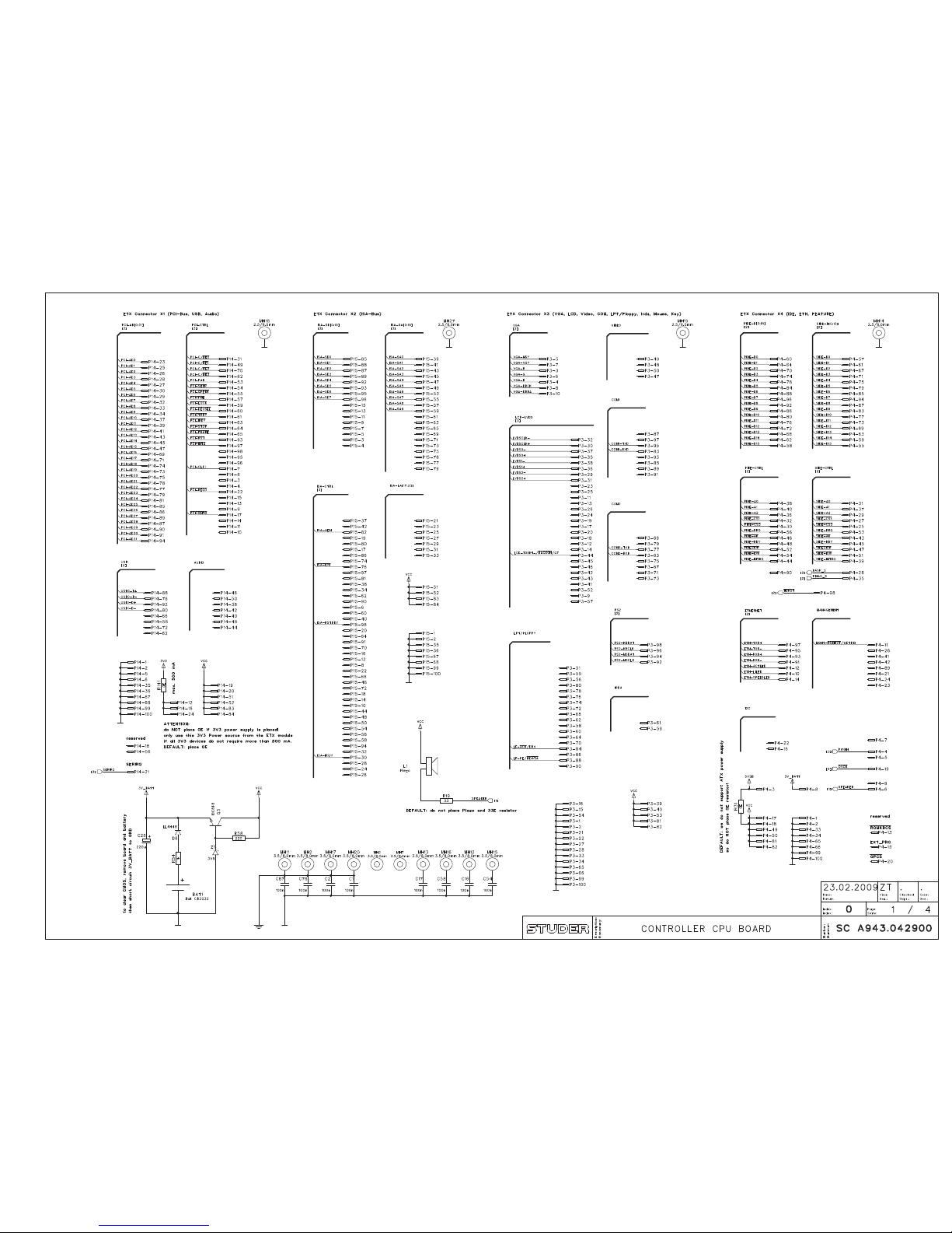
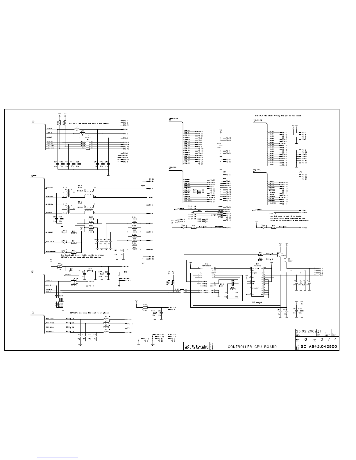
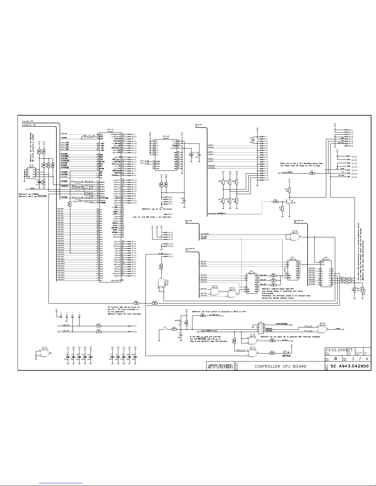
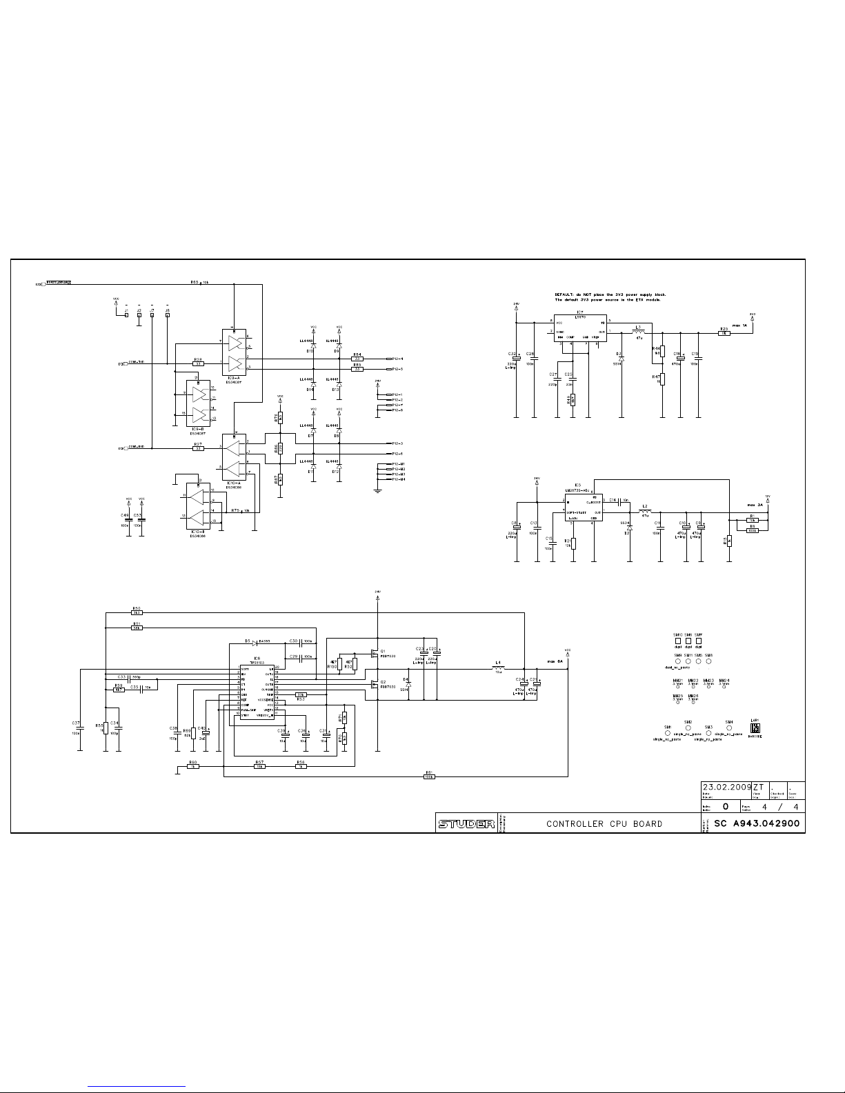
Controller CPU PCB
A
943.042900
Controller Front PCB
A
943.041220
Channel Screen Module
A
943.056200
Channel Screen Module w. DVI input
A
943.056400
Channel Screen Module w. DVI in + LBP8
A
943.056600
Controller CPU PCB (see Main Screen Module)
A
943.042900
6-Fader Module (LED)
A
943.042082
6-Fader Front PCB
A
943.042181
Fader Control PCB
A
943.042222
6-Fader Module (OLED + Motor Faders)
A
943.061000
6-Fader Module (OLED)
A
943.061500
6-Fader OLED Front PCB
A
943.061122
Fader OLED Control PCB
A
943.061223
Fader OLED Control PCB, partial
A
943.061322
3-Fader Module (LED)
A
943.046082
3-Fader Module DR (LED)
A
943.046382
3-Fader Front PCB
A
943.046181
Fader Control PCB (see 6-Fader Module w. LED Display)
A
943.04222
2
Fader Assign Module
A
943.042500
Fader Assign Front PCB
A
943.042620
A
ssign Control PCB
A
943.042721
Rotary Module
A
943.043000
Rotary Front PCB
A
943.043100
Fader Control PCB (see 6-Fader Module w. LED Display)
A
943.04222
2
Rotary Assign Module
A
943.043500
Rotary Assign Front PCB
A
943.043600
A
ssign Control PCB (see Fader Assign Module)
A
943.042721
Monitoring Module CR / St1, Modulo
A
943.044081
Monitoring Module CR / St1, FixFrame
A
943. 044581
Monitoring Module St2/3, Modulo
A
943. 044781
Monitoring Module St2/3, FixFrame
A
943. 044481
Monitoring Module DR, Modulo
A
943.048081
Monitoring/Timer Module
A
943.048382
Monitoring Front PCB
A
943.044181
Monitoring Front PCB DR
A
943.048181
Speaker Swap PCB
A
943.048200
Monitoring/Timer Front PCB
A
943.048481
A
/B Switch PCB
A
943.048700
TOSLink IF PCB
A
943.044900
Monitoring Audio Control PCB
A
943.044225
Monitoring Audio Control PCB FixFrame
(
Diagram/Component Layout: seeA943.044225)
A
943.044824
Surround Control Module
A
943.043700
Surround Control Front PCB
A
943.043820
A
ssign Control PCB (see Fader Assign Module)
A
943.042721
Editor Module
A
943.046582
Editor Front PCB
A
943.046681
Fader Control PCB (see 6-Fader Module w. LED Display)
A
943.04222
2
XL Module
A
943.049000
XL Front PCB
A
943.049120
A
ssign Control PCB (see Fader Assign Module)
A
943.042721
Headphone Box
A
943.049281
Headphone PCB
A
943.049383
Mic Key (GPIO 1) Box
A
943.049400
Mic Key Front PCB
A
943.049500
Start Button (GPIO 2) Box
A
943.049600
Start Button Front PCB
(
Diagram/Component Layout: see A943.0495)
A
943.049700
Cart (GPIO 3) Box
A
943.049800
Carts Front PCB
A
943.049900
A
ssign Control PCB (see Fader Assign Module)
A
943.042721
Distribution Boxes without/with redundant PSU
A
943.045000 / .045600
Extension Distribution Boxes without/with redundant PSU
A
943.045400 / .045500
Distribution Main PCB
A
943.045121
Distribution Merger PCB
A
943.045221
Distribution LED PCB
A
943.045300
Page 24

2-2
Date printed: 28.02.11
Page 25
2-3
Date printed: 28.02.11
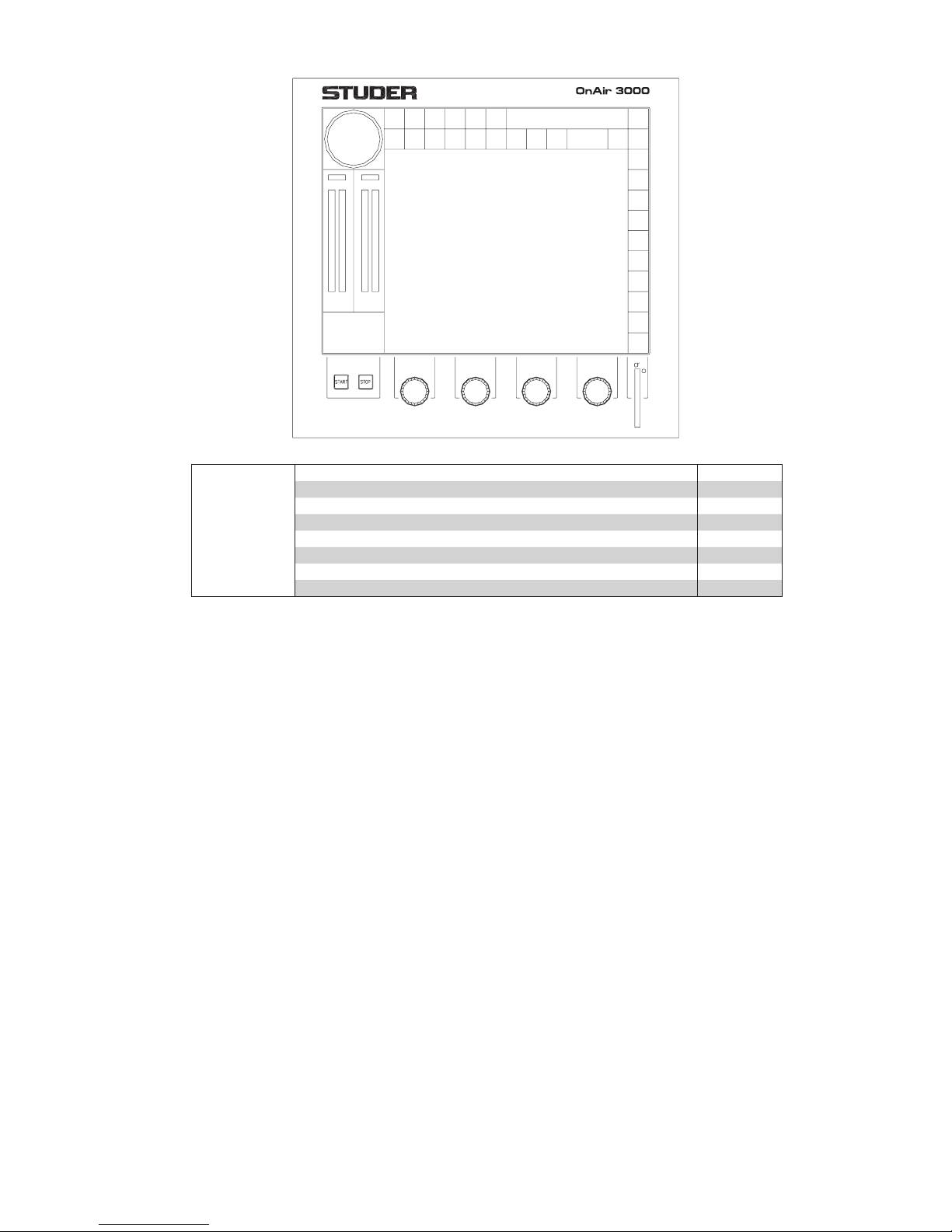
Main Screen Module A943.056000
DIGITAL MIXING CONSOLE
Consists of:
Controller CPU PCB A943.042900
Controller Front PCB A943.041220
Touch Module C073.010167
TFT Module C073.010181
Inverter for Backlight C073.010182
CF Memory Card C089.200307
ETX Board 600 MHz C089.201184
DDR RAM 256 MB C050.631657
Page 26

2-4
Date printed: 28.02.11
Channel Screen Module A943.056200
Channel Screen Module w. DVI Input A943.056400
Channel Screen Module w. DVI Input & LBP8 A943.056600
Consists of:
Controller CPU PCB A943.042900
Touch Module C073.010167
TFT Module C073.010181
Inverter for Backlight C073.010182
CF Memory Card C089.200307
ETX Board 600 MHz C089.201184
Controller CPU PCB A943.042900
DDR RAM 256 MB C050.631657
Page 27
2-5
Date printed: 28.02.11
Page 28
2-6
Date printed: 28.02.11
Page 29
2-7
Date printed: 28.02.11
Page 30
2-8
Date printed: 28.02.11
Page 31

2-9
Date printed: 28.02.11
Page 32

2-10
Date printed: 28.02.11
Page 33

2-11
Date printed: 28.02.11
OnAir 3000 Digital Mixing Console
Controller CPU PCB A943.042900
Page: 1 of 2
Rev RefDes Order no. Qty Value Description
0 BAT1 C089.012703 1 BATTERY HOLDER 20MM PCB MTG,
0 C1 C059.603337 1 100n CAP SM CER 100NF 10% 50VX5R 0805
0 C2 C059.603337 1 100n CAP SM CER 100NF 10% 50VX5R 0805
0 C3 C059.603337 1 100n CAP SM CER 100NF 10% 50VX5R 0805
0 C4 C059.603337 1 100n CAP SM CER 100NF 10% 50VX5R 0805
0 C5 C059.603337 1 100n CAP SM CER 100NF 10% 50VX5R 0805
0 C6 C059.603337 1 100n CAP SM CER 100NF 10% 50VX5R 0805
0 C7 C059.603337 1 100n CAP SM CER 100NF 10% 50VX5R 0805
0 C8 C059.680317 1 220u CAP SM ELC 220UF 35V LOW-ESR 85°C
0 C9 C059.680275 1 470u CAP SM ELC 470UF 16V LOW-ESR 85°C
0 C10 C059.680275 1 470u CAP SM ELC 470UF 16V LOW-ESR 85°C
0 C11 C059.603337 1 100n CAP SM CER 100NF 10% 50VX5R 0805
0 C12 C059.603337 1 100n CAP SM CER 100NF 10% 50VX5R 0805
0 C13 C059.603337 1 100n CAP SM CER 100NF 10% 50VX5R 0805
0 C14 C059.603325 1 10n CAP SM CER 10NF 10% 50V X7R 0805
0 C15 C059.603337 1 100n CAP SM CER 100NF 10% 50VX5R 0805
0 C16 C059.603337 1 100n CAP SM CER 100NF 10% 50VX5R 0805
0 C17 C059.603337 1 100n CAP SM CER 100NF 10% 50VX5R 0805
0 C20 C059.680317 1 220u CAP SM ELC 220UF 35V LOW-ESR 85°C
0 C21 C059.680275 1 470u CAP SM ELC 470UF 16V LOW-ESR 85°C
0 C22 C059.603337 1 100n CAP SM CER 100NF 10% 50VX5R 0805
0 C23 C059.680317 1 220u CAP SM ELC 220UF 35V LOW-ESR 85°C
0 C24 C059.680275 1 470u CAP SM ELC 470UF 16V LOW-ESR 85°C
0 C26 C059.680031 1 220u CAP SM ELC 220UF 6.3V 85°C
0 C29 C059.603337 1 100n CAP SM CER 100NF 10% 50VX5R 0805
0 C30 C059.603337 1 100n CAP SM CER 100NF 10% 50VX5R 0805
0 C31 C059.680109 1 10u CAP SM ELC 10UF 35V 85°C
0 C33 C059.602363 1 390p CAP SM CER 390PF 5% 50V NPO 0805
0 C34 C059.602249 1 100p CAP SM CER 100PF 5% 50V NPO 0603
0 C35 C059.603325 1 10n CAP SM CER 10NF 10% 50V X7R 0805
0 C36 C059.680109 1 10u CAP SM ELC 10UF 35V 85°C
0 C37 C059.603337 1 100n CAP SM CER 100NF 10% 50VX5R 0805
0 C38 C059.602249 1 100p CAP SM CER 100PF 5% 50V NPO 0603
0 C39 C059.680109 1 10u CAP SM ELC 10UF 35V 85°C
0 C40 C059.680129 1 2u2 CAP SM ELC 2.2UF 50V 85°C
0 C41 C059.603337 1 100n CAP SM CER 100NF 10% 50VX5R 0805
0 C42 C059.603325 1 10n CAP SM CER 10NF 10% 50V X7R 0805
0 C43 C059.603325 1 10n CAP SM CER 10NF 10% 50V X7R 0805
0 C44 C059.603325 1 10n CAP SM CER 10NF 10% 50V X7R 0805
0 C45 C059.603325 1 10n CAP SM CER 10NF 10% 50V X7R 0805
0 C47 C059.603325 1 10n CAP SM CER 10NF 10% 50V X7R 0805
0 C48 C059.603337 1 100n CAP SM CER 100NF 10% 50VX5R 0805
0 C49 C059.603337 1 100n CAP SM CER 100NF 10% 50VX5R 0805
0 C50 C059.603325 1 10n CAP SM CER 10NF 10% 50V X7R 0805
0 C51 C059.603325 1 10n CAP SM CER 10NF 10% 50V X7R 0805
0 C53 C059.603337 1 100n CAP SM CER 100NF 10% 50VX5R 0805
0 C54 C059.603337 1 100n CAP SM CER 100NF 10% 50VX5R 0805
0 C56 C059.602233 1 22p CAP SM CER 22PF 5% 50V NPO 0603
0 C57 C059.680127 1 1u CAP SM ELC 1.0UF 50V 85°C
0 C58 C059.603337 1 100n CAP SM CER 100NF 10% 50VX5R 0805
0 C59 C059.603337 1 100n CAP SM CER 100NF 10% 50VX5R 0805
0 C60 C059.603337 1 100n CAP SM CER 100NF 10% 50VX5R 0805
0 C61 C059.603337 1 100n CAP SM CER 100NF 10% 50VX5R 0805
0 C62 C059.603337 1 100n CAP SM CER 100NF 10% 50VX5R 0805
0 C63 C059.603325 1 10n CAP SM CER 10NF 10% 50V X7R 0805
0 C64 C059.603325 1 10n CAP SM CER 10NF 10% 50V X7R 0805
0 C65 C059.603337 1 100n CAP SM CER 100NF 10% 50VX5R 0805
0 C66 C059.603337 1 100n CAP SM CER 100NF 10% 50VX5R 0805
0 C67 C059.602249 1 100p CAP SM CER 100PF 5% 50V NPO 0603
0 C68 C059.603337 1 100n CAP SM CER 100NF 10% 50VX5R 0805
0 C69 C059.602233 1 22p CAP SM CER 22PF 5% 50V NPO 0603
0 C76 C059.603337 1 100n CAP SM CER 100NF 10% 50VX5R 0805
0 C77 C059.680029 1 100u CAP SM ELC 100UF 6.3V 85°C
0 C80 C059.603337 1 100n CAP SM CER 100NF 10% 50VX5R 0805
0 C82 C059.603337 1 100n CAP SM CER 100NF 10% 50VX5R 0805
0 C87 C059.603337 1 100n CAP SM CER 100NF 10% 50VX5R 0805
0 C88 C059.603337 1 100n CAP SM CER 100NF 10% 50VX5R 0805
0 D1 C050.608001 1 LL4448 DSL LL4448
0 D2 C050.608102 1 SS34 DSK 40V 3A MBRS340T3G
0 D4 C050.608103 1 SS14 DSK 40V 1A SS14-E3/13T
0 D5 C050.608101 1 BAS85 DSK BAS85
0 D6 C050.608001 1 LL4448 DSL LL4448
0 D7 C050.608001 1 LL4448 DSL LL4448
0 D8 C050.608001 1 LL4448 DSL LL4448
0 D9 C050.608001 1 LL4448 DSL LL4448
0 D10 C050.608001 1 LL4448 DSL LL4448
0 D11 C050.608001 1 LL4448 DSL LL4448
0 D12 C050.608001 1 LL4448 DSL LL4448
0 D13 C050.608001 1 LL4448 DSL LL4448
Rev RefDes Order no. Qty Value Description
0 D14 C050.608001 1 LL4448 DSL LL4448
0 DL1 C050.609412 1 red SMD LED RED LST670-LM 2.7X3.5
0 DL2 C050.609412 1 red SMD LED RED LST670-LM 2.7X3.5
0 DL5 C050.609414 1 grn LED GREEN CLEAR TOP SMD
0 DL6 C050.609414 1 grn LED GREEN CLEAR TOP SMD
0 IC1 C050.650000 1 74LVC IC 74LVCAD 4X2I/P NAND
0 IC2 C050.650138 1 74LVC138 IC 74LVC138AD 3:8 LDCDR
0 IC3 C050.650138 1 74LVC138 IC 74LVC138AD 3:8 LDCDR
0 IC4 C050.650273 1 74LVC273 OCTAL D-TYPE F/F
0 IC5 C050.612005 1 LM2673S-
A
DJ VREG LM2673SX 3A ADJ
0 IC6 C050.650008 1 74LVC8 IC 74LVC8AD 4X2I/P AND
0 IC8 C050.612004 1 TPS5 103 SYNC DC/DC CNVTR ADJ
0 IC9 C050.620464 1 DS34C87 QUAD DRVR RS-42 2
0 IC10 C050.620463 1 DS34C86 LINE RCVR RS-422 QUAD
0 IC11 C050.618109 1 TLC2543C TLC2543CDW 12-BIT ADC SO-20
0 IC12 C050.630218 1 HS12100SO TOUCH SCREEN CNTRL SO-18
0 IC13 C050.630211 1 PCI1510 CARD CNTRL QFP-144
0 L2 C062.600518 1 47u INDCT SM 47uH 2.5
A
0 L4 C062.600510 1 10u INDCT SM 10uH 6.5
A
0 L7 C062.600903 1 HF BEAD FERRITE 600R 0.1
A
0 L8 C062.600903 1 HF BEAD FERRITE 600R 0.1
A
0 MP1A943.041113 1 PCB CONTROLLER CPU
0 MP2
A
943.042910 1 NR. ETIKETTE 5x20
0 MP3 C043.010108 1 Label LABEL - ESD CARE WARNING
0 MP101 C050.609416 1 3.7/7*12 LIGHTPIPE 3.7X7MM 12MM LG.PCB
0 MP102 C022.324125 1 M2.5*3 NUT M2.5 RIVETED PCB TYPESTEEL.
0 MP104 C021.518354 1 M3*6 SCRW M3X6MM BTN/HD SKT SNP ISO7380
0 MP105 C022.015030 1 M3 NUT M3 BZPCA-FIX005
0 MP106 C024.162030 1 3.2/6.0 WSHR M3 EXT S/PROOF ST/STL DIN6798
0 P2 C054.120416 1 50p CF CARD HEADER R/A TYPE 2 SMT
0 P3 C054.600250 1 FX8-100S-S
V
CON 100WAY SKT VERT 0.6MM (BD-BD)SM
0 P4 C054.600250 1 FX8-100S-S
V
CON 100WAY SKT VERT 0.6MM (BD-BD)SM
0 P6 C073.010168 1 KCA 4 CON 4WY FOR 12" T/SCREEN
0 P7 C054.145640 1 Micromatch_20CON 20WY PCB SKT MICRO-MATCH
0 P10 C054.201104 1 USB_4 CON USB TYPE A SKT VERT PCB/MTG
0 P11 C054.201005 1 RJ4 5_8 CON RJ45 SKT SHLD PCB/MNT
0 P12 C054.201005 1 RJ4 5_8 CON RJ45 SKT SHLD PCB/MNT
0 P14 C054.600250 1 FX8-100S-S
V
CON 100WAY SKT VERT 0.6MM (BD-BD)SM
0 P15 C054.600250 1 FX8-100S-S
V
CON 100WAY SKT VERT 0.6MM (BD-BD)SM
0 P17 C054.145640 1 Micromatch_20CON 20WY PCB SKT MICRO-MATCH
0 P18 C054.145640 1 Micromatch_20CON 20WY PCB SKT MICRO-MATCH
0 P19 C054.145640 1 Micromatch_20CON 20WY PCB SKT MICRO-MATCH
0 P20 C054.145628 1 Micromatch_8 CON 8WY PCB SKT MICRO-MATCH
0 Q1 C050.602202 1 FDB7030 MOSFET FDB7030 30V 50A N-CH PWR
0 Q2 C050.602202 1 FDB7030 MOSFET FDB7030 30V 50A N-CH PWR
0 Q3 C050.600003 1 BC846 TRS BC846B NPN
0 Q4 C050.600001 1 BC847 TRS BC847B NPN
0 Q6 C050.601050 1 BC807 TRS BC807-25 PNP
0 Q7 C050.601050 1 BC807 TRS BC807-25 PNP
0 R1 C057.611103 1 10
k
RES SM 10K 1% 0.1W 0603
0 R2 C057.611103 1 10
k
RES SM 10K 1% 0.1W 0603
0 R3 C057.611103 1 10
k
RES SM 10K 1% 0.1W 0603
0 R4 C057.691000 1 0E RES SM 0R 1% 0.1W 0603
0 R7 C057.691000 1 0E RES SM 0R 1% 0.1W 0603
0 R8 C057.611104 1 100
k
RES SM 100K 1% 0.1W 0603
0 R9 C057.611222 1 2k2 RES SM 2K2 1% 0.1W 0603
0 R10 C057.611561 1 560 RES SM 560R 1% 0.1W 0603
0 R11 C057.611472 1 4k7 RES SM 4K7 1% 0.1W 0603
0 R12 C057.611102 1 1k RES SM 1K 1% 0.1W 0603
0 R13 C057.611471 1 470 RES SM 470R 1% 0.1W 0603
0 R14 C057.611330 1 33 RES SM 33R 1% 0.1W 0603
0 R15 C057.611102 1 1k RES SM 1K 1% 0.1W 0603
0 R16 C057.691000 1 0E RES SM 0R 1% 0.1W 0603
0 R17 C057.611103 1 10
k
RES SM 10K 1% 0.1W 0603
0 R18 C057.611103 1 10
k
RES SM 10K 1% 0.1W 0603
0 R21 C057.611123 1 12
k
RES SM 12K 1% 0.1W 0603
0 R22 C057.611103 1 10
k
RES SM 10K 1% 0.1W 0603
0 R23 C057.691000 1 0E RES SM 0R 1% 0.1W 0603
0 R24 C057.611221 1 220 RES SM 220R 1% 0.1W 0603
0 R26 C057.611182 1 1k8 RES SM 1K8 1% 0.1W 0603
0 R27 C057.611330 1 33 RES SM 33R 1% 0.1W 0603
0 R28 C057.611330 1 33 RES SM 33R 1% 0.1W 0603
0 R29 C057.611330 1 33 RES SM 33R 1% 0.1W 0603
0 R30 C057.611330 1 33 RES SM 33R 1% 0.1W 0603
0 R32 C057.611103 1 10
k
RES SM 10K 1% 0.1W 0603
0 R33 C057.611330 1 33 RES SM 33R 1% 0.1W 0603
0 R34 C057.611330 1 33 RES SM 33R 1% 0.1W 0603
0 R35 C057.611103 1 10
k
RES SM 10K 1% 0.1W 0603
0 R36 C057.611330 1 33 RES SM 33R 1% 0.1W 0603
Page 34

2-12
Date printed: 28.02.11
OnAir 3000 Digital Mixing Console
Controller CPU PCB A943.042900
Page: 2 of 2
Rev RefDes Order no. Qty Value Description
0 R37 C057.611330 1 33 RES SM 33R 1% 0.1W 0603
0 R38 C057.611103 1 10k RES SM 10K 1% 0.1W 0603
0 R39 C057.611103 1 10
k
RES SM 10K 1% 0.1W 0603
0 R40 C057.611103 1 10
k
RES SM 10K 1% 0.1W 0603
0 R41 C057.611330 1 33 RES SM 33R 1% 0.1W 0603
0 R43 C057.611103 1 10
k
RES SM 10K 1% 0.1W 0603
0 R45 C057.611331 1 330 RES SM 330R 1% 0.1W 0603
0 R50 C057.611332 1 3k3 RES SM 3K3 1% 0.1W 0603
0 R51 C057.611563 1 56
k
RES SM 56K 1% 0.1W 0603
0 R52 C057.611479 1 4E7 RES SM 4R7 1% 0.1W 0603
0 R53 C057.611333 1 33
k
RES SM 33K 1% 0.1W 0603
0 R54 C057.611102 1 1k RES SM 1K 1% 0.1W 0603
0 R55 C057.611102 1 1k RES SM 1K 1% 0.1W 0603
0 R56 C057.611102 1 1k RES SM 1K 1% 0.1W 0603
0 R57 C057.611153 1 15
k
RES SM 15K 1% 0.1W 0603
0 R58 C057.611221 1 220 RES SM 220R 1% 0.1W 0603
0 R59 C057.611472 1 4k7 RES SM 4K7 1% 0.1W 0603
0 R60 C057.611102 1 1k RES SM 1K 1% 0.1W 0603
0 R61 C057.611104 1 100
k
RES SM 100K 1% 0.1W 0603
0 R63 C057.611331 1 330 RES SM 330R 1% 0.1W 0603
0 R64 C057.611331 1 330 RES SM 330R 1% 0.1W 0603
0 R65 C057.611103 1 10
k
RES SM 10K 1% 0.1W 0603
0 R66 C057.611102 1 1k RES SM 1K 1% 0.1W 0603
0 R69 C057.611823 1 82
k
RES SM 82K 1% 0.1W 0603
0 R70 C057.611152 1 1k5 RES SM 1K5 1% 0.1W 0603
0 R71 C057.611103 1 10
k
RES SM 10K 1% 0.1W 0603
0 R73 C057.691000 1 0E RES SM 0R 1% 0.1W 0603
0 R74 C057.691000 1 0E RES SM 0R 1% 0.1W 0603
0 R75 C057.611103 1 10
k
RES SM 10K 1% 0.1W 0603
0 R76 C057.611152 1 1k5 RES SM 1K5 1% 0.1W 0603
0 R77 C057.611564 1 560
k
RES SM 560K 1% 0.1W 0603
0 R78 C057.611153 1 15
k
RES SM 15K 1% 0.1W 0603
0 R79 C057.611153 1 15
k
RES SM 15K 1% 0.1W 0603
0 R80 C057.611151 1 150 RES SM 150R 1% 0.1W 0603
0 R81 C057.611151 1 150 RES SM 150R 1% 0.1W 0603
0 R82 C057.611151 1 150 RES SM 150R 1% 0.1W 0603
0 R83 C057.611151 1 150 RES SM 150R 1% 0.1W 0603
0 R84 C057.611330 1 33 RES SM 33R 1% 0.1W 0603
0 R85 C057.611330 1 33 RES SM 33R 1% 0.1W 0603
0 R86 C057.611221 1 220 RES SM 220R 1% 0.1W 0603
0 R87 C057.611152 1 1k5 RES SM 1K5 1% 0.1W 0603
0 R89 C057.611102 1 1k RES SM 1K 1% 0.1W 0603
0 R90 C057.611102 1 1k RES SM 1K 1% 0.1W 0603
0 R91 C057.611474 1 470
k
RES SM 470K 1% 0.1W 0603
0 R92 C057.611222 1 2k2 RES SM 2K2 1% 0.1W 0603
0 R93 C057.611222 1 2k2 RES SM 2K2 1% 0.1W 0603
0 R95 C057.691000 1 0E RES SM 0R 1% 0.1W 0603
0 R96 C057.691000 1 0E RES SM 0R 1% 0.1W 0603
0 R97 C057.691000 1 0E RES SM 0R 1% 0.1W 0603
0 R98 C057.611105 1 1M RES SM 1M0 1% 0.1W 0603
0 R99 C057.611151 1 150 RES SM 150R 1% 0.1W 0603
0 R100 C057.611151 1 150 RES SM 150R 1% 0.1W 0603
0 R101 C057.691000 1 0E RES SM 0R 1% 0.1W 0603
0 R102 C057.691000 1 0E RES SM 0R 1% 0.1W 0603
0 R104 C057.611103 1 10
k
RES SM 10K 1% 0.1W 0603
0 R106 C057.611103 1 10
k
RES SM 10K 1% 0.1W 0603
0 R107 C057.611103 1 10
k
RES SM 10K 1% 0.1W 0603
0 R108 C057.611103 1 10
k
RES SM 10K 1% 0.1W 0603
0 R109 C057.611103 1 10
k
RES SM 10K 1% 0.1W 0603
0 R110 C057.611103 1 10
k
RES SM 10K 1% 0.1W 0603
0 R111 C057.611103 1 10
k
RES SM 10K 1% 0.1W 0603
0 R112 C057.691000 1 0E RES SM 0R 1% 0.1W 0603
0 R114 C057.611221 1 220 RES SM 220R 1% 0.1W 0603
0 R119 C057.611330 1 33 RES SM 33R 1% 0.1W 0603
0 R120 C057.611330 1 33 RES SM 33R 1% 0.1W 0603
0 R121 C057.927051 1 1.1
A
FUSE RESETTABLE 1.1A RAD5 /!
\
0 R124 C057.611222 1 2k2 RES SM 2K2 1% 0.1W 0603
0 R125 C057.611222 1 2k2 RES SM 2K2 1% 0.1W 0603
0 R126 C057.611330 1 33 RES SM 33R 1% 0.1W 0603
0 R127 C057.611332 1 3k3 RES SM 3K3 1% 0.1W 0603
0 R139 C057.611221 1 220 RES SM 220R 1% 0.1W 0603
0 R140 C057.691000 1 0E RES SM 0R 1% 0.1W 0603
0 R141 C057.691000 1 0E RES SM 0R 1% 0.1W 0603
0 R142 C057.611153 1 15
k
RES SM 15K 1% 0.1W 0603
0 R143 C057.611153 1 15
k
RES SM 15K 1% 0.1W 0603
0 R144 C057.611151 1 150 RES SM 150R 1% 0.1W 0603
0 R145 C057.611151 1 150 RES SM 150R 1% 0.1W 0603
0 R146 C057.611151 1 150 RES SM 150R 1% 0.1W 0603
0 R147 C057.611151 1 150 RES SM 150R 1% 0.1W 0603
Rev RefDes Order no. Qty Value Description
0 R148 C057.611151 1 150 RES SM 150R 1% 0.1W 0603
0 R149 C057.611151 1 150 RES SM 150R 1% 0.1W 0603
0 R150 C057.611479 1 4E7 RES SM 4R7 1% 0.1W 0603
0 S1 C055.600104 1 SWT SM DIL 4W LOW PROFILE
0 S2 C055.600201 1 SWT PUSH SM TACT TYPE V/MNT
0 T1 C63.600021 1 H1102 IC H1102NLT TXMR 10/100SINGLE PORT
0 Y1 C089.601011 1 6.000MHz CRYSTAL 6.000MHZ 100PPMSMD
0 Z1 C050.609007 1 3V9 DZR 3.9V 200MW 5% BZX84C3V9
0 Z2 C050.609011 1 5V6 ZENER DIODE 300MW 5.6V
0 Z3 C050.609011 1 5V6 ZENER DIODE 300MW 5.6V
0 Z4 C050.609011 1 5V6 ZENER DIODE 300MW 5.6V
0 Z5 C050.609011 1 5V6 ZENER DIODE 300MW 5.6V
Page 35

2-13
Date printed: 28.02.11
Page 36

2-14
Date printed: 28.02.11
Page 37

2-15
Date printed: 28.02.11
Page 38

2-16
Date printed: 28.02.11
Page 39

2-17
Date printed: 28.02.11
OnAir 3000 Digital Mixing Console
Controller Front PCB A943.041220
Page: 1 of 2
Rev RefDes Order no. Qty Value Description
0 C1 C059.603337 1 100n CAP SM CER 100NF 10% 50VX5R 0805
0 C2 C059.603337 1 100n CAP SM CER 100NF 10% 50VX5R 0805
0 C3 C059.602237 1 33p CAP SM CER 33PF 5% 50V 0603
0 C4 C059.602233 1 22p CAP SM CER 22PF 5% 50V NPO 0603
0 C5 C059.680069 1 47u CAP SM ELC 47UF 16V 85°C
0 C6 C059.602237 1 33p CAP SM CER 33PF 5% 50V 0603
0 C7 C059.602233 1 22p CAP SM CER 22PF 5% 50V NPO 0603
0 C8 C059.680069 1 47u CAP SM ELC 47UF 16V 85°C
0 C9 C059.680067 1 22u CAP SM ELC 22UF 16V 85°C
0 C10 C059.680027 1 47u CAP SM ELC 47UF 6.3V 85°C
0 C11 C059.603337 1 100n CAP SM CER 100NF 10% 50VX5R 0805
0 C12 C059.680067 1 22u CAP SM ELC 22UF 16V 85°C
0 C13 C059.603337 1 100n CAP SM CER 100NF 10% 50VX5R 0805
0 C14 C059.603321 1 4n7 CAP SM CER 4.7NF 10% 50VX7R 0805
0 C15 C059.603321 1 4n7 CAP SM CER 4.7NF 10% 50VX7R 0805
0 C16 C059.603321 1 4n7 CAP SM CER 4.7NF 10% 50VX7R 0805
0 C17 C059.603321 1 4n7 CAP SM CER 4.7NF 10% 50VX7R 0805
0 C18 C059.603321 1 4n7 CAP SM CER 4.7NF 10% 50VX7R 0805
0 C19 C059.603321 1 4n7 CAP SM CER 4.7NF 10% 50VX7R 0805
0 C20 C059.603321 1 4n7 CAP SM CER 4.7NF 10% 50VX7R 0805
0 C21 C059.603321 1 4n7 CAP SM CER 4.7NF 10% 50VX7R 0805
0 C22 C059.603337 1 100n CAP SM CER 100NF 10% 50VX5R 0805
0 C23 C059.603337 1 100n CAP SM CER 100NF 10% 50VX5R 0805
0 C24 C059.602373 1 1n CAP SM CER 1.0NF 5% 50V NPO 0805
0 C25 C059.603337 1 100n CAP SM CER 100NF 10% 50VX5R 0805
0 C26 C059.603337 1 100n CAP SM CER 100NF 10% 50VX5R 0805
0 C27 C059.603337 1 100n CAP SM CER 100NF 10% 50VX5R 0805
0 C28 C059.603337 1 100n CAP SM CER 100NF 10% 50VX5R 0805
0 C29 C059.603337 1 100n CAP SM CER 100NF 10% 50VX5R 0805
0 C30 C059.603337 1 100n CAP SM CER 100NF 10% 50VX5R 0805
0 C31 C059.603337 1 100n CAP SM CER 100NF 10% 50VX5R 0805
0 C32 C059.603337 1 100n CAP SM CER 100NF 10% 50VX5R 0805
0 C33 C059.603337 1 100n CAP SM CER 100NF 10% 50VX5R 0805
0 C34 C059.603337 1 100n CAP SM CER 100NF 10% 50VX5R 0805
0 C35 C059.603337 1 100n CAP SM CER 100NF 10% 50VX5R 0805
0 C36 C059.680025 1 22u CAP SM ELC 22UF 6.3V 85°C
0 C37 C059.680025 1 22u CAP SM ELC 22UF 6.3V 85°C
0 C38 C059.603337 1 100n CAP SM CER 100NF 10% 50VX5R 0805
0 C39 C059.603337 1 100n CAP SM CER 100NF 10% 50VX5R 0805
0 D1 C050.608003 1 S1B DRC S1B 100V 1
A
0 D2 C050.608001 1 LL4448 DSL LL4448
0 D3 C050.608001 1 LL4448 DSL LL4448
0 D4 C050.608001 1 LL4448 DSL LL4448
0 D5 C050.608001 1 LL4448 DSL LL4448
0 D6 C050.608001 1 LL4448 DSL LL4448
0 D7 C050.608001 1 LL4448 DSL LL4448
0 D8 C050.608001 1 LL4448 DSL LL4448
0 D9 C050.608001 1 LL4448 DSL LL4448
0 DL1 C050.609401 1 red LED RED CLEAR TOP SMD
0 DL2 C050.609402 1 yel LED YELLOW CLEAR TOP SMD
0 DL3 C050.609402 1 yel LED YELLOW CLEAR TOP SMD
0 IC1 C050.621014 1 74HC14 IC MM74HC14 HEX INVTR SCMTT TRGR
0 IC2 C050.621595 1 74HC595 IC MC74HC595A 8BIT SI/SO/PO S/REGT
R
0 IC3 C050.632001 1 TL7705B RST GENRTR SO-8
0 IC4 C050.612003 1 LM1117DT VOLT REG 1.25V/13.8V 0.8
A
0 IC5 C050.621904 1 74HCU04 IC 74HCU04 HEX INVTR UNBUFFD CMOS
0 IC6 C050.621014 1 74HC14 IC MM74HC14 HEX INVTR SCMTT TRGR
0 IC7 S943.091220 1 89S53 SW 412 CONTROLLER FRONT BRD-VIST
A
0 IC8 S943.091020 1 EPLD3064 SW 412/426 ROTEC-CNTL FRT BD VISTA (OB)
0 IC9 C050.621573 1 74HC573 IC M74HC573RM D-TYPE LATCH
2 IC10 C050.631504 1 uPD431000
A
SRAM 128KX8 70NS LOPWR SO32
0 L1
A
942.001500 1 BRAKE Incremental Encoder Brake
0 L2
A
942.001500 1 BRAKE Incremental Encoder Brake
0 L3
A
942.001500 1 BRAKE Incremental Encoder Brake
0 L4
A
942.001500 1 BRAKE Incremental Encoder Brake
0 MP1
A
943.041211 1 CONTROLLER FRONT BOARD
0 MP2
A
943.041210 1 NR-ETIKETTE 5 * 20
0 MP3 C043.010108 1 Label LABEL - ESD CARE WARNING
0 MP4
A
943.041202 1 RUBBER KEY 2 KEYS
0 MP5 C043.100111 1 B LABEL - REVISION "B" DISC STUDER
0 P1 C054.600301 1
A
MP-
COMPACT_50
CON 50WAY CF CARD HEADERVERT SM
0 P2 C054.142001 1 Latch_10 CON 10WY ML IDC LO/PRF V/MNT
0 P3
A
023.039210 1 Ribbon cable 20-Pole L=0.10m
0 P4
A
023.039210 1 Ribbon cable 20-Pole L=0.10m
0 P5
A
023.039210 1 Ribbon cable 20-Pole L=0.10m
0 Q1 C050.600001 1 BC847 TRS BC847B NPN
0 Q2 C050.600001 1 BC847 TRS BC847B NPN
0 Q3 C050.600001 1 BC847 TRS BC847B NPN
Rev RefDes Order no. Qty Value Description
0 Q4 C050.600001 1 BC847 TRS BC847B NPN
0 Q5 C050.600001 1 BC847 TRS BC847B NPN
0 Q6 C050.600001 1 BC847 TRS BC847B NPN
0 Q7 C050.600001 1 BC847 TRS BC847B NPN
0 Q8 C050.600001 1 BC847 TRS BC847B NPN
0 R2 C057.601391 1 390 RES SM 390R 1% 0.25W MINIMELF 50PPM 020
1 R3 C057.601152 1 1k5 RES SM 1K5 1% 0.25W MINIMELF 50PPM 0204
1 R4 C057.601152 1 1k5 RES SM 1K5 1% 0.25W MINIMELF 50PPM 0204
0 R5 C057.691097 1 10
k
RES SM 10K 5% 0.1W 0603
0 R6 C057.691097 1 10
k
RES SM 10K 5% 0.1W 0603
0 R7 C057.691097 1 10
k
RES SM 10K 5% 0.1W 0603
0 R8 C057.691097 1 10
k
RES SM 10K 5% 0.1W 0603
1 R9 C057.601560 1 56 RES SM 56R 1% 0.25W MINIMELF 50PPM 0204
0 R10 C057.691097 1 10
k
RES SM 10K 5% 0.1W 0603
0 R11 C057.691097 1 10
k
RES SM 10K 5% 0.1W 0603
0 R12 C057.691097 1 10
k
RES SM 10K 5% 0.1W 0603
0 R13 C057.691097 1 10
k
RES SM 10K 5% 0.1W 0603
0 R14 C057.691097 1 10
k
RES SM 10K 5% 0.1W 0603
1 R15 C057.601272 1 2k7 RES SM 2K7 1% 0.25W MINIMELF 50PPM 0204
1 R16 C057.601561 1 560 RES SM 560R 1% 0.25W MINIMELF 50PPM 020
1 R17 C057.601152 1 1k5 RES SM 1K5 1% 0.25W MINIMELF 50PPM 0204
0 R18 C057.691097 1 10
k
RES SM 10K 5% 0.1W 0603
0 R19 C057.691097 1 10
k
RES SM 10K 5% 0.1W 0603
1 R20 C057.601103 1 10
k
RES SM 10K 1% 0.25W MINIMELF 50PPM 0204
0 R21 C057.691097 1 10
k
RES SM 10K 5% 0.1W 0603
0 R22 C057.691097 1 10
k
RES SM 10K 5% 0.1W 0603
1 R23 C057.601151 1 150 RES SM 150R 1% 0.25W MINIMELF 50PPM 020
0 R24 C057.601470 1 47 RES SM 47R 1% 0.25W MINIMELF 50PPM 0204
1 R25 C057.601472 1 4k7 RES SM 4K7 1% 0.25W MINIMELF 50PPM 0204
1 R26 C057.601104 1 100
k
RES SM 100K 1% 0.25W MINIMELF 50PPM 020
1 R27 C057.601104 1 100
k
RES SM 100K 1% 0.25W MINIMELF 50PPM 020
1 R28 C057.601472 1 4k7 RES SM 4K7 1% 0.25W MINIMELF 50PPM 0204
1 R29 C057.601151 1 150 RES SM 150R 1% 0.25W MINIMELF 50PPM 020
0 R30 C057.601470 1 47 RES SM 47R 1% 0.25W MINIMELF 50PPM 0204
1 R31 C057.601472 1 4k7 RES SM 4K7 1% 0.25W MINIMELF 50PPM 0204
1 R32 C057.601104 1 100
k
RES SM 100K 1% 0.25W MINIMELF 50PPM 020
1 R33 C057.601104 1 100
k
RES SM 100K 1% 0.25W MINIMELF 50PPM 020
1 R34 C057.601472 1 4k7 RES SM 4K7 1% 0.25W MINIMELF 50PPM 0204
1 R35 C057.601151 1 150 RES SM 150R 1% 0.25W MINIMELF 50PPM 020
0 R36 C057.601470 1 47 RES SM 47R 1% 0.25W MINIMELF 50PPM 0204
1 R37 C057.601472 1 4k7 RES SM 4K7 1% 0.25W MINIMELF 50PPM 0204
1 R38 C057.601104 1 100
k
RES SM 100K 1% 0.25W MINIMELF 50PPM 020
1 R39 C057.601104 1 100
k
RES SM 100K 1% 0.25W MINIMELF 50PPM 020
1 R40 C057.601472 1 4k7 RES SM 4K7 1% 0.25W MINIMELF 50PPM 0204
1 R41 C057.601151 1 150 RES SM 150R 1% 0.25W MINIMELF 50PPM 020
0 R42 C057.601470 1 47 RES SM 47R 1% 0.25W MINIMELF 50PPM 0204
1 R43 C057.601472 1 4k7 RES SM 4K7 1% 0.25W MINIMELF 50PPM 0204
1 R44 C057.601104 1 100
k
RES SM 100K 1% 0.25W MINIMELF 50PPM 020
1 R45 C057.601104 1 100
k
RES SM 100K 1% 0.25W MINIMELF 50PPM 020
1 R46 C057.601472 1 4k7 RES SM 4K7 1% 0.25W MINIMELF 50PPM 0204
1 R47 C057.601105 1 1M RES SM 1M0 1% 0.25W MINIMELF 50PPM 0204
1 R48 C057.601472 1 4k7 RES SM 4K7 1% 0.25W MINIMELF 50PPM 0204
1 R49 C057.601472 1 4k7 RES SM 4K7 1% 0.25W MINIMELF 50PPM 0204
1 R50 C057.601271 1 270 RES SM 270R 1% 0.25W MINIMELF 50PPM 020
1 R51 C057.601271 1 270 RES SM 270R 1% 0.25W MINIMELF 50PPM 020
1 R52 C057.601100 1 10 RES SM 10R 1% 0.25W MINIMELF 50PPM 020
0 R53 C057.691097 1 10
k
RES SM 10K 5% 0.1W 0603
0 R54 C057.691097 1 10
k
RES SM 10K 5% 0.1W 0603
1 R55 C057.601472 1 4k7 RES SM 4K7 1% 0.25W MINIMELF 50PPM 0204
1 R56 C057.601472 1 4k7 RES SM 4K7 1% 0.25W MINIMELF 50PPM 0204
1 R57 C057.601472 1 4k7 RES SM 4K7 1% 0.25W MINIMELF 50PPM 0204
1 R58 C057.601472 1 4k7 RES SM 4K7 1% 0.25W MINIMELF 50PPM 0204
1 R59 C057.601472 1 4k7 RES SM 4K7 1% 0.25W MINIMELF 50PPM 0204
1 R60 C057.601472 1 4k7 RES SM 4K7 1% 0.25W MINIMELF 50PPM 0204
0 R61 C057.691097 1 10
k
RES SM 10K 5% 0.1W 0603
0 R62 C057.691097 1 10
k
RES SM 10K 5% 0.1W 0603
0 R63 C057.691097 1 10
k
RES SM 10K 5% 0.1W 0603
0 R64 C057.691097 1 10
k
RES SM 10K 5% 0.1W 0603
0 R65 C057.691097 1 10
k
RES SM 10K 5% 0.1W 0603
1 R66 C057.601103 1 10
k
RES SM 10K 1% 0.25W MINIMELF 50PPM 0204
0 R67 C057.691097 1 10
k
RES SM 10K 5% 0.1W 0603
0 R68 C057.691097 1 10
k
RES SM 10K 5% 0.1W 0603
1 R69 C057.601152 1 1k5 RES SM 1K5 1% 0.25W MINIMELF 50PPM 0204
1 R70 C057.601472 1 4k7 RES SM 4K7 1% 0.25W MINIMELF 50PPM 0204
0 R71 C057.691097 1 10
k
RES SM 10K 5% 0.1W 0603
0 R72 C057.691097 1 10
k
RES SM 10K 5% 0.1W 0603
0 R73 C057.601101 1 100 RES SM 100R 1% 0.25W MINIMELF 50PPM 020
0 R74 C057.691097 1 10
k
RES SM 10K 5% 0.1W 0603
0 R75 C057.691097 1 10
k
RES SM 10K 5% 0.1W 0603
Page 40

2-18
Date printed: 28.02.11
OnAir 3000 Digital Mixing Console
Controller Front PCB A943.041220
Page: 2 of 2
Rev RefDes Order no. Qty Value Description
1 R76 C057.601102 1 1k RES SM 1K 1% 0.25W MINIMELF 50PPM 0204
1 R77 C057.601102 1 1k RES SM 1K 1% 0.25W MINIMELF 50PPM 0204
1 R78 C057.601102 1 1k RES SM 1K 1% 0.25W MINIMELF 50PPM 0204
1 R79 C057.601102 1 1k RES SM 1K 1% 0.25W MINIMELF 50PPM 0204
1 R80 C057.601103 1 10
k
RES SM 10K 1% 0.25W MINIMELF 50PPM 0204
1 R81 C057.601152 1 1k5 RES SM 1K5 1% 0.25W MINIMELF 50PPM 0204
0 R82 C057.691097 1 10
k
RES SM 10K 5% 0.1W 0603
0 S3 C055.121302 1 EC16B ROTARY ENCODER 16MM 24 PULSE
0 S4 C055.121302 1 EC16B ROTARY ENCODER 16MM 24 PULSE
0 S5 C055.121302 1 EC16B ROTARY ENCODER 16MM 24 PULSE
0 S6 C055.121302 1 EC16B ROTARY ENCODER 16MM 24 PULSE
0 S7 C055.600201 1 SWT PUSH SM TACT TYPE V/MNT
0 TP1 C054.020320 1 - **USE FF1117** FASTON TAB 2.8MM VERT PCB
0 TP2 C054.020320 1 - **USE FF1117** FASTON TAB 2.8MM VERT PCB
0 XIC7 C053.032244 1 44p SKT IC 44WY PLCC PCB/MNT
0 Y1 C089.601011 1 6.000MHz CRYSTAL 6.000MHZ 100PPMSMD
0 Y2 C089.601004 1 22.1184MHz CRYSTAL 22.1184MHZ 100PPM SMD.
Page 41

2-19
Date printed: 28.02.11
6-Fader Module A943.042082
6-Fader Module DR A943.042382
Consists of:
Fader Front PCB A943.042181
Fader Control PCB A943.042222
Module Firmware S943.091320
Module Firmware DR S943.092320
6 Faders* 100 mm 10 k lin. A960.003500
*If Alps faders are replaced by P&G faders (A960.003500), an additional
connecting cable is required per fader: A943.042093
Modulo
accessories:
Case A943.042014
2 x Mounting Bracket A943.042007
4 x Screw C021.512354
Page 42

2-20
Date printed: 28.02.11
Page 43

2-21
Date printed: 28.02.11
Page 44

2-22
Date printed: 28.02.11
Page 45

2-23
Date printed: 28.02.11
Page 46

2-24
Date printed: 28.02.11
Page 47

2-25
Date printed: 28.02.11
Page 48

2-26
Date printed: 28.02.11
Page 49

2-27
Date printed: 28.02.11
Page 50

2-28
Date printed: 28.02.11
OnAir 3000 Digital Mixing Console
6-Fader Front PCB A943.042181
Page: 1 of 5
Rev RefDes Order no. Qty Value Description
0 C1 C059.603337 1 100n CAP SM CER 100NF 10% 50VX5R 0805
0 C2 C059.680069 1 47u CAP SM ELC 47UF 16V 85°C
0 C3 C059.603337 1 100n CAP SM CER 100NF 10% 50VX5R 0805
0 C4 C059.680069 1 47u CAP SM ELC 47UF 16V 85°C
0 C5 C059.603337 1 100n CAP SM CER 100NF 10% 50VX5R 0805
0 C6 C059.680069 1 47u CAP SM ELC 47UF 16V 85°C
0 C7 C059.603337 1 100n CAP SM CER 100NF 10% 50VX5R 0805
0 C8 C059.603337 1 100n CAP SM CER 100NF 10% 50VX5R 0805
0 C9 C059.603337 1 100n CAP SM CER 100NF 10% 50VX5R 0805
0 C10 C059.603337 1 100n CAP SM CER 100NF 10% 50VX5R 0805
0 C11 C059.603337 1 100n CAP SM CER 100NF 10% 50VX5R 0805
0 C12 C059.603337 1 100n CAP SM CER 100NF 10% 50VX5R 0805
0 C13 C059.603337 1 100n CAP SM CER 100NF 10% 50VX5R 0805
0 C14 C059.603337 1 100n CAP SM CER 100NF 10% 50VX5R 0805
0 C15 C059.603337 1 100n CAP SM CER 100NF 10% 50VX5R 0805
0 C16 C059.603337 1 100n CAP SM CER 100NF 10% 50VX5R 0805
0 C17 C059.603337 1 100n CAP SM CER 100NF 10% 50VX5R 0805
0 C18 C059.603337 1 100n CAP SM CER 100NF 10% 50VX5R 0805
0 C19 C059.603337 1 100n CAP SM CER 100NF 10% 50VX5R 0805
0 C20 C059.603337 1 100n CAP SM CER 100NF 10% 50VX5R 0805
0 C21 C059.680069 1 47u CAP SM ELC 47UF 16V 85°C
0 C22 C059.603337 1 100n CAP SM CER 100NF 10% 50VX5R 0805
0 C23 C059.603337 1 100n CAP SM CER 100NF 10% 50VX5R 0805
0 C24 C059.602249 1 100p CAP SM CER 100PF 5% 50V NPO 0603
0 C25 C059.602233 1 22p CAP SM CER 22PF 5% 50V NPO 0603
0 C26 C059.602243 1 56p CAP SM CER 56PF 5% 50V NPO 0603
0 C27 C059.603321 1 4n7 CAP SM CER 4.7NF 10% 50VX7R 0805
0 C28 C059.603321 1 4n7 CAP SM CER 4.7NF 10% 50VX7R 0805
0 C29 C059.603321 1 4n7 CAP SM CER 4.7NF 10% 50VX7R 0805
0 C30 C059.603321 1 4n7 CAP SM CER 4.7NF 10% 50VX7R 0805
0 C31 C059.603321 1 4n7 CAP SM CER 4.7NF 10% 50VX7R 0805
0 C32 C059.603321 1 4n7 CAP SM CER 4.7NF 10% 50VX7R 0805
0 C33 C059.603321 1 4n7 CAP SM CER 4.7NF 10% 50VX7R 0805
0 C34 C059.603321 1 4n7 CAP SM CER 4.7NF 10% 50VX7R 0805
0 C35 C059.603321 1 4n7 CAP SM CER 4.7NF 10% 50VX7R 0805
0 C36 C059.603321 1 4n7 CAP SM CER 4.7NF 10% 50VX7R 0805
0 C37 C059.603321 1 4n7 CAP SM CER 4.7NF 10% 50VX7R 0805
0 C38 C059.603321 1 4n7 CAP SM CER 4.7NF 10% 50VX7R 0805
0 C39 C059.602373 1 1n CAP SM CER 1.0NF 5% 50V NPO 0805
0 C40 C059.602249 1 100p CAP SM CER 100PF 5% 50V NPO 0603
0 C41 C059.603337 1 100n CAP SM CER 100NF 10% 50VX5R 0805
0 C42 C059.603337 1 100n CAP SM CER 100NF 10% 50VX5R 0805
0 C43 C059.603317 1 2n2 CAP SM CER 2.2NF 10% 50VX7R 0805
0 C44 C059.603337 1 100n CAP SM CER 100NF 10% 50VX5R 0805
0 C45 C059.603337 1 100n CAP SM CER 100NF 10% 50VX5R 0805
0 C46 C059.603337 1 100n CAP SM CER 100NF 10% 50VX5R 0805
0 C47 C059.603337 1 100n CAP SM CER 100NF 10% 50VX5R 0805
0 C48 C059.603337 1 100n CAP SM CER 100NF 10% 50VX5R 0805
0 C49 C059.603337 1 100n CAP SM CER 100NF 10% 50VX5R 0805
0 C50 C059.603337 1 100n CAP SM CER 100NF 10% 50VX5R 0805
0 C51 C059.603337 1 100n CAP SM CER 100NF 10% 50VX5R 0805
0 C52 C059.603337 1 100n CAP SM CER 100NF 10% 50VX5R 0805
0 C53 C059.603337 1 100n CAP SM CER 100NF 10% 50VX5R 0805
0 C54 C059.603337 1 100n CAP SM CER 100NF 10% 50VX5R 0805
0 C55 C059.603337 1 100n CAP SM CER 100NF 10% 50VX5R 0805
0 C56 C059.603337 1 100n CAP SM CER 100NF 10% 50VX5R 0805
0 C57 C059.603337 1 100n CAP SM CER 100NF 10% 50VX5R 0805
0 C58 C059.603337 1 100n CAP SM CER 100NF 10% 50VX5R 0805
0 C59 C059.603337 1 100n CAP SM CER 100NF 10% 50VX5R 0805
0 C60 C059.603337 1 100n CAP SM CER 100NF 10% 50VX5R 0805
0 C61 C059.603337 1 100n CAP SM CER 100NF 10% 50VX5R 0805
0 C62 C059.603337 1 100n CAP SM CER 100NF 10% 50VX5R 0805
0 C63 C059.603337 1 100n CAP SM CER 100NF 10% 50VX5R 0805
0 C64 C059.603337 1 100n CAP SM CER 100NF 10% 50VX5R 0805
0 C65 C059.603337 1 100n CAP SM CER 100NF 10% 50VX5R 0805
0 C66 C059.603337 1 100n CAP SM CER 100NF 10% 50VX5R 0805
0 C67 C059.603337 1 100n CAP SM CER 100NF 10% 50VX5R 0805
0 C68 C059.603337 1 100n CAP SM CER 100NF 10% 50VX5R 0805
0 C69 C059.603337 1 100n CAP SM CER 100NF 10% 50VX5R 0805
0 C70 C059.603337 1 100n CAP SM CER 100NF 10% 50VX5R 0805
0 C71 C059.603337 1 100n CAP SM CER 100NF 10% 50VX5R 0805
0 C72 C059.603337 1 100n CAP SM CER 100NF 10% 50VX5R 0805
0 C73 C059.603337 1 100n CAP SM CER 100NF 10% 50VX5R 0805
0 C74 C059.603337 1 100n CAP SM CER 100NF 10% 50VX5R 0805
0 C75 C059.603337 1 100n CAP SM CER 100NF 10% 50VX5R 0805
0 C76 C059.603337 1 100n CAP SM CER 100NF 10% 50VX5R 0805
0 C77 C059.603337 1 100n CAP SM CER 100NF 10% 50VX5R 0805
0 C78 C059.603337 1 100n CAP SM CER 100NF 10% 50VX5R 0805
0 C79 C059.603337 1 100n CAP SM CER 100NF 10% 50VX5R 0805
Rev RefDes Order no. Qty Value Description
0 C80 C059.603337 1 100n CAP SM CER 100NF 10% 50VX5R 0805
0 C81 C059.603337 1 100n CAP SM CER 100NF 10% 50VX5R 0805
0 C82 C059.603337 1 100n CAP SM CER 100NF 10% 50VX5R 0805
0 C83 C059.603337 1 100n CAP SM CER 100NF 10% 50VX5R 0805
0 C84 C059.603337 1 100n CAP SM CER 100NF 10% 50VX5R 0805
0 C85 C059.603337 1 100n CAP SM CER 100NF 10% 50VX5R 0805
0 C86 C059.603337 1 100n CAP SM CER 100NF 10% 50VX5R 0805
0 C87 C059.603337 1 100n CAP SM CER 100NF 10% 50VX5R 0805
0 C88 C059.603337 1 100n CAP SM CER 100NF 10% 50VX5R 0805
0 D1 C050.608001 1 LL4448 DSL LL4448
0 D2 C050.608001 1 LL4448 DSL LL4448
0 D3 C050.608001 1 LL4448 DSL LL4448
0 D4 C050.608001 1 LL4448 DSL LL4448
0 D5 C050.608001 1 LL4448 DSL LL4448
0 D6 C050.608001 1 LL4448 DSL LL4448
0 D7 C050.608001 1 LL4448 DSL LL4448
0 D8 C050.608001 1 LL4448 DSL LL4448
0 D9 C050.608001 1 LL4448 DSL LL4448
0 D10 C050.608001 1 LL4448 DSL LL4448
0 D11 C050.608001 1 LL4448 DSL LL4448
0 D12 C050.608001 1 LL4448 DSL LL4448
0 D13 C050.608001 1 LL4448 DSL LL4448
0 D14 C050.608001 1 LL4448 DSL LL4448
0 D15 C050.608001 1 LL4448 DSL LL4448
0 D16 C050.608001 1 LL4448 DSL LL4448
0 D17 C050.608001 1 LL4448 DSL LL4448
0 D18 C050.608001 1 LL4448 DSL LL4448
0 D19 C050.608001 1 LL4448 DSL LL4448
0 D20 C050.608001 1 LL4448 DSL LL4448
0 D21 C050.608001 1 LL4448 DSL LL4448
0 D22 C050.608001 1 LL4448 DSL LL4448
0 D23 C050.608001 1 LL4448 DSL LL4448
0 D24 C050.608001 1 LL4448 DSL LL4448
0 D25 C050.608001 1 LL4448 DSL LL4448
0 D26 C050.608001 1 LL4448 DSL LL4448
0 D27 C050.608001 1 LL4448 DSL LL4448
0 D28 C050.608001 1 LL4448 DSL LL4448
0 D29 C050.608001 1 LL4448 DSL LL4448
0 D30 C050.608001 1 LL4448 DSL LL4448
0 D31 C050.608001 1 LL4448 DSL LL4448
0 D32 C050.608001 1 LL4448 DSL LL4448
0 D33 C050.608001 1 LL4448 DSL LL4448
0 D34 C050.608001 1 LL4448 DSL LL4448
0 D35 C050.608001 1 LL4448 DSL LL4448
0 D36 C050.608001 1 LL4448 DSL LL4448
0 D37 C050.608001 1 LL4448 DSL LL4448
0 D38 C050.608001 1 LL4448 DSL LL4448
0 D39 C050.608001 1 LL4448 DSL LL4448
0 D40 C050.608001 1 LL4448 DSL LL4448
0 D41 C050.608001 1 LL4448 DSL LL4448
0 D42 C050.608001 1 LL4448 DSL LL4448
0 D43 C050.608001 1 LL4448 DSL LL4448
0 D44 C050.608001 1 LL4448 DSL LL4448
0 D45 C050.608001 1 LL4448 DSL LL4448
0 D46 C050.608001 1 LL4448 DSL LL4448
0 D47 C050.608001 1 LL4448 DSL LL4448
0 D48 C050.608001 1 LL4448 DSL LL4448
0 D49 C050.608001 1 LL4448 DSL LL4448
0 D50 C050.608001 1 LL4448 DSL LL4448
0 D51 C050.608001 1 LL4448 DSL LL4448
0 D52 C050.608001 1 LL4448 DSL LL4448
0 D53 C050.608001 1 LL4448 DSL LL4448
0 D54 C050.608001 1 LL4448 DSL LL4448
0 D55 C050.608001 1 LL4448 DSL LL4448
0 D56 C050.608001 1 LL4448 DSL LL4448
0 D57 C050.608001 1 LL4448 DSL LL4448
0 D58 C050.608001 1 LL4448 DSL LL4448
0 D59 C050.608001 1 LL4448 DSL LL4448
0 D60 C050.608001 1 LL4448 DSL LL4448
0 DL1 C050.042860 1 LED RING 21 SEGMENT
0 DL2 C050.042860 1 LED RING 21 SEGMENT
0 DL3 C050.042860 1 LED RING 21 SEGMENT
0 DL4 C050.042860 1 LED RING 21 SEGMENT
0 DL5 C050.042860 1 LED RING 21 SEGMENT
0 DL6 C050.042860 1 LED RING 21 SEGMENT
0 DL7 C050.609402 1 yel LED YELLOW CLEAR TOP SMD
0 DL8 C050.609402 1 yel LED YELLOW CLEAR TOP SMD
0 DL9 C050.609402 1 yel LED YELLOW CLEAR TOP SMD
0 DL10 C050.609402 1 yel LED YELLOW CLEAR TOP SMD
Page 51

2-29
Date printed: 28.02.11
OnAir 3000 Digital Mixing Console
6-Fader Front PCB A943.042181
Page: 2 of 5
Rev RefDes Order no. Qty Value Description
0 DL11 C050.609402 1 yel LED YELLOW CLEAR TOP SMD
0 DL12 C050.609402 1 yel LED YELLOW CLEAR TOP SMD
0 DL13 C050.609402 1 yel LED YELLOW CLEAR TOP SMD
0 DL14 C050.609401 1 red LED RED CLEAR TOP SMD
0 DL15 C050.609402 1 yel LED YELLOW CLEAR TOP SMD
0 DL16 C050.609401 1 red LED RED CLEAR TOP SMD
0 DL17 C050.609402 1 yel LED YELLOW CLEAR TOP SMD
0 DL18 C050.609401 1 red LED RED CLEAR TOP SMD
0 DL19 C050.609402 1 yel LED YELLOW CLEAR TOP SMD
0 DL20 C050.609401 1 red LED RED CLEAR TOP SMD
0 DL21 C050.609402 1 yel LED YELLOW CLEAR TOP SMD
0 DL22 C050.609401 1 red LED RED CLEAR TOP SMD
0 DL23 C050.609402 1 yel LED YELLOW CLEAR TOP SMD
0 DL24 C050.609401 1 red LED RED CLEAR TOP SMD
0 DL25 C050.609402 1 yel LED YELLOW CLEAR TOP SMD
0 DL26 C050.609401 1 red LED RED CLEAR TOP SMD
0 DL27 C050.609402 1 yel LED YELLOW CLEAR TOP SMD
0 DL28 C050.609401 1 red LED RED CLEAR TOP SMD
0 DL29 C050.609402 1 yel LED YELLOW CLEAR TOP SMD
0 DL30 C050.609401 1 red LED RED CLEAR TOP SMD
0 DL31 C050.609402 1 yel LED YELLOW CLEAR TOP SMD
0 DL32 C050.609401 1 red LED RED CLEAR TOP SMD
0 DL33 C050.609402 1 yel LED YELLOW CLEAR TOP SMD
0 DL34 C050.609401 1 red LED RED CLEAR TOP SMD
0 DL35 C050.609402 1 yel LED YELLOW CLEAR TOP SMD
0 DL36 C050.609401 1 red LED RED CLEAR TOP SMD
0 DL37 C050.609402 1 yel LED YELLOW CLEAR TOP SMD
0 DL38 C050.609401 1 red LED RED CLEAR TOP SMD
0 DL39 C050.609402 1 yel LED YELLOW CLEAR TOP SMD
0 DL40 C050.609401 1 red LED RED CLEAR TOP SMD
0 DL41 C050.609402 1 yel LED YELLOW CLEAR TOP SMD
0 DL42 C050.609401 1 red LED RED CLEAR TOP SMD
0 DL43 C050.609402 1 yel LED YELLOW CLEAR TOP SMD
0 DL44 C050.609401 1 red LED RED CLEAR TOP SMD
0 DL45 C050.609402 1 yel LED YELLOW CLEAR TOP SMD
0 DL46 C050.609401 1 red LED RED CLEAR TOP SMD
0 DL47 C050.609402 1 yel LED YELLOW CLEAR TOP SMD
0 DL48 C050.609401 1 red LED RED CLEAR TOP SMD
0 DL49 C050.609418 1 blu LED BLUE DIFFUSED TOP SMD
0 DL50 C050.609418 1 blu LED BLUE DIFFUSED TOP SMD
0 DL51 C050.609418 1 blu LED BLUE DIFFUSED TOP SMD
0 DL52 C050.609418 1 blu LED BLUE DIFFUSED TOP SMD
0 DL53 C050.609418 1 blu LED BLUE DIFFUSED TOP SMD
0 DL54 C050.609418 1 blu LED BLUE DIFFUSED TOP SMD
0 DL55 C050.042813 1 red/grn LED BARGRAPH 4RED-6GREENDIP
0 DL56 C050.042813 1 red/grn LED BARGRAPH 4RED-6GREENDIP
0 DL57 C050.042813 1 red/grn LED BARGRAPH 4RED-6GREENDIP
0 DL58 C050.042813 1 red/grn LED BARGRAPH 4RED-6GREENDIP
0 DL59 C050.042813 1 red/grn LED BARGRAPH 4RED-6GREENDIP
0 DL60 C050.042813 1 red/grn LED BARGRAPH 4RED-6GREENDIP
0 DL61 C050.042150 1 red LED BARGRAPH RED 10SEG.DIP.
0 DL62 C050.042150 1 red LED BARGRAPH RED 10SEG.DIP.
0 DL63 C050.042150 1 red LED BARGRAPH RED 10SEG.DIP.
0 DL64 C050.042150 1 red LED BARGRAPH RED 10SEG.DIP.
0 DL65 C050.042150 1 red LED BARGRAPH RED 10SEG.DIP.
0 DL66 C050.042150 1 red LED BARGRAPH RED 10SEG.DIP.
0 DL67 C050.609402 1 yel LED YELLOW CLEAR TOP SMD
0 DL68 C050.609401 1 red LED RED CLEAR TOP SMD
0 DL69 C050.609402 1 yel LED YELLOW CLEAR TOP SMD
0 DL70 C050.609401 1 red LED RED CLEAR TOP SMD
0 DL71 C050.609402 1 yel LED YELLOW CLEAR TOP SMD
0 DL72 C050.609401 1 red LED RED CLEAR TOP SMD
0 DL73 C050.609402 1 yel LED YELLOW CLEAR TOP SMD
0 DL74 C050.609401 1 red LED RED CLEAR TOP SMD
0 DL75 C050.609402 1 yel LED YELLOW CLEAR TOP SMD
0 DL76 C050.609401 1 red LED RED CLEAR TOP SMD
0 DL77 C050.609402 1 yel LED YELLOW CLEAR TOP SMD
0 DL78 C050.609401 1 red LED RED CLEAR TOP SMD
0 DL79 C050.609402 1 yel LED YELLOW CLEAR TOP SMD
0 DL80 C050.609401 1 red LED RED CLEAR TOP SMD
0 DL81 C050.609402 1 yel LED YELLOW CLEAR TOP SMD
0 DL82 C050.609401 1 red LED RED CLEAR TOP SMD
0 DL83 C050.609402 1 yel LED YELLOW CLEAR TOP SMD
0 DL84 C050.609401 1 red LED RED CLEAR TOP SMD
0 DL85 C050.609402 1 yel LED YELLOW CLEAR TOP SMD
0 DL86 C050.609401 1 red LED RED CLEAR TOP SMD
0 DL87 C050.609402 1 yel LED YELLOW CLEAR TOP SMD
0 DL88 C050.609401 1 red LED RED CLEAR TOP SMD
0 DL89 C050.609402 1 yel LED YELLOW CLEAR TOP SMD
Rev RefDes Order no. Qty Value Description
0 DL90 C050.609401 1 red LED RED CLEAR TOP SMD
0 IC1 C073.010409 1 HCMS2913 8CH 7BY5 DOT MTX DISP SER GRN
0 IC2 C073.010409 1 HCMS2913 8CH 7BY5 DOT MTX DISP SER GRN
0 IC3 C073.010409 1 HCMS2913 8CH 7BY5 DOT MTX DISP SER GRN
0 IC4 C073.010409 1 HCMS2913 8CH 7BY5 DOT MTX DISP SER GRN
0 IC5 C073.010409 1 HCMS2913 8CH 7BY5 DOT MTX DISP SER GRN
0 IC6 C073.010409 1 HCMS2913 8CH 7BY5 DOT MTX DISP SER GRN
0 IC7 C050.621595 1 74HC595 IC MC74HC595A 8BIT SI/SO/PO S/REGT
R
0 IC8 C050.621014 1 74HC14 IC MM74HC14 HEX INVTR SCMTT TRGR
0 IC9 C050.621014 1 74HC14 IC MM74HC14 HEX INVTR SCMTT TRGR
0 IC10 C050.621595 1 74HC595 IC MC74HC595A 8BIT SI/SO/PO S/REGT
R
0 IC11 C050.619001 1 LM393 DUAL VOLT CMPARTR
0 IC12 C050.621165 1 74HC165 IC MC74HC165A 8BIT PI/SOS/REGT
R
0 IC13 C050.621595 1 74HC595 IC MC74HC595A 8BIT SI/SO/PO S/REGT
R
0 IC14 C050.621165 1 74HC165 IC MC74HC165A 8BIT PI/SOS/REGT
R
0 IC15 C050.621595 1 74HC595 IC MC74HC595A 8BIT SI/SO/PO S/REGT
R
0 IC16 C050.621595 1 74HC595 IC MC74HC595A 8BIT SI/SO/PO S/REGT
R
0 IC17 C050.621595 1 74HC595 IC MC74HC595A 8BIT SI/SO/PO S/REGT
R
0 IC18 C050.621595 1 74HC595 IC MC74HC595A 8BIT SI/SO/PO S/REGT
R
0 IC19 C050.621595 1 74HC595 IC MC74HC595A 8BIT SI/SO/PO S/REGT
R
0 IC20 C050.621595 1 74HC595 IC MC74HC595A 8BIT SI/SO/PO S/REGT
R
0 IC21 C050.621595 1 74HC595 IC MC74HC595A 8BIT SI/SO/PO S/REGT
R
0 IC22 C050.621595 1 74HC595 IC MC74HC595A 8BIT SI/SO/PO S/REGT
R
0 IC23 C050.621595 1 74HC595 IC MC74HC595A 8BIT SI/SO/PO S/REGT
R
0 IC24 C050.621595 1 74HC595 IC MC74HC595A 8BIT SI/SO/PO S/REGT
R
0 IC25 C050.621595 1 74HC595 IC MC74HC595A 8BIT SI/SO/PO S/REGT
R
0 IC26 C050.621595 1 74HC595 IC MC74HC595A 8BIT SI/SO/PO S/REGT
R
0 IC27 C050.621595 1 74HC595 IC MC74HC595A 8BIT SI/SO/PO S/REGT
R
0 IC28 C050.621595 1 74HC595 IC MC74HC595A 8BIT SI/SO/PO S/REGT
R
0 IC29 C050.621595 1 74HC595 IC MC74HC595A 8BIT SI/SO/PO S/REGT
R
0 IC30 C050.621595 1 74HC595 IC MC74HC595A 8BIT SI/SO/PO S/REGT
R
0 IC31 C050.621595 1 74HC595 IC MC74HC595A 8BIT SI/SO/PO S/REGT
R
0 IC32 C050.621595 1 74HC595 IC MC74HC595A 8BIT SI/SO/PO S/REGT
R
0 IC33 C050.621595 1 74HC595 IC MC74HC595A 8BIT SI/SO/PO S/REGT
R
0 IC34 C050.621595 1 74HC595 IC MC74HC595A 8BIT SI/SO/PO S/REGT
R
0 IC35 C050.621595 1 74HC595 IC MC74HC595A 8BIT SI/SO/PO S/REGT
R
0 IC36 C050.618109 1 TLC2543C TLC2543CDW 12-BIT ADC SO-20
0 IC37 C050.621541 1 74HC541 IC MM74HC541 OCTAL BFFR
0 IC38 C050.621595 1 74HC595 IC MC74HC595A 8BIT SI/SO/PO S/REGT
R
0 IC39 C050.621165 1 74HC165 IC MC74HC165A 8BIT PI/SOS/REGT
R
0 IC40 C050.621595 1 74HC595 IC MC74HC595A 8BIT SI/SO/PO S/REGT
R
0 IC41 C050.621595 1 74HC595 IC MC74HC595A 8BIT SI/SO/PO S/REGT
R
0 IC42 C050.621595 1 74HC595 IC MC74HC595A 8BIT SI/SO/PO S/REGT
R
0 IC43 C050.621595 1 74HC595 IC MC74HC595A 8BIT SI/SO/PO S/REGT
R
0 IC44 C050.610201 1 TL62 JFET OP-AMP
0 IC45 C050.621595 1 74HC595 IC MC74HC595A 8BIT SI/SO/PO S/REGT
R
0 IC46 C050.621595 1 74HC595 IC MC74HC595A 8BIT SI/SO/PO S/REGT
R
0 IC47 C050.621951 1 74HC4051 IC 74HC405D 8:1 ANLOG MPLX
0 IC48 C050.621595 1 74HC595 IC MC74HC595A 8BIT SI/SO/PO S/REGT
R
0 MP1A943.042112 1 FADER FRONT PCB
0 MP2
A
943.042110 1 NR-ETIKETTE 5 * 20
0 MP3 C043.010108 1 Label LABEL - ESD CARE WARNING
0 MP4
A
943.042130 1 RUBBER KEY Set 1-CH
0 P1
A
023.039116 1 Ribbon cable 14-Pole L=0.15m
0 P2
A
023.039116 1 Ribbon cable 14-Pole L=0.15m
0 P3
A
023.039116 1 Ribbon cable 14-Pole L=0.15m
0 P4 C054.120705 1 EI_5 CON 5WY HDR 0.1" LATCH ML
0 P5 C054.120705 1 EI_5 CON 5WY HDR 0.1" LATCH ML
0 P6 C054.120705 1 EI_5 CON 5WY HDR 0.1" LATCH ML
0 P7 C054.120705 1 EI_5 CON 5WY HDR 0.1" LATCH ML
0 P8 C054.120705 1 EI_5 CON 5WY HDR 0.1" LATCH ML
0 P9 C054.120705 1 EI_5 CON 5WY HDR 0.1" LATCH ML
0 Q1 C050.601101 1 FMMT717 TRS FMMT717 PNP
0 Q2 C050.601101 1 FMMT717 TRS FMMT717 PNP
0 Q3 C050.601101 1 FMMT717 TRS FMMT717 PNP
0 Q4 C050.601101 1 FMMT717 TRS FMMT717 PNP
0 Q5 C050.601101 1 FMMT717 TRS FMMT717 PNP
0 Q6 C050.601101 1 FMMT717 TRS FMMT717 PNP
0 Q7 C050.601101 1 FMMT717 TRS FMMT717 PNP
0 Q8 C050.601101 1 FMMT717 TRS FMMT717 PNP
0 Q9 C050.600050 1 BC817 TRS BC817-25 NPN
0 Q10 C050.600050 1 BC817 TRS BC817-25 NPN
0 Q11 C050.600050 1 BC817 TRS BC817-25 NPN
0 Q12 C050.600050 1 BC817 TRS BC817-25 NPN
0 Q13 C050.600050 1 BC817 TRS BC817-25 NPN
0 Q14 C050.600050 1 BC817 TRS BC817-25 NPN
0 Q15 C050.601101 1 FMMT717 TRS FMMT717 PNP
0 Q16 C050.600050 1 BC817 TRS BC817-25 NPN
0 Q17 C050.600050 1 BC817 TRS BC817-25 NPN
Page 52

2-30
Date printed: 28.02.11
OnAir 3000 Digital Mixing Console
6-Fader Front PCB A943.042181
Page: 3 of 5
Rev RefDes Order no. Qty Value Description
0 Q18 C050.600050 1 BC817 TRS BC817-25 NPN
0 Q19 C050.601101 1 FMMT717 TRS FMMT717 PNP
0 Q20 C050.601101 1 FMMT717 TRS FMMT717 PNP
0 Q21 C050.600050 1 BC817 TRS BC817-25 NPN
0 Q22 C050.600050 1 BC817 TRS BC817-25 NPN
0 Q23 C050.600050 1 BC817 TRS BC817-25 NPN
0 Q24 C050.601101 1 FMMT717 TRS FMMT717 PNP
0 Q25 C050.600050 1 BC817 TRS BC817-25 NPN
0 Q26 C050.600050 1 BC817 TRS BC817-25 NPN
0 Q27 C050.600050 1 BC817 TRS BC817-25 NPN
0 Q28 C050.600050 1 BC817 TRS BC817-25 NPN
0 Q29 C050.600050 1 BC817 TRS BC817-25 NPN
0 Q30 C050.600050 1 BC817 TRS BC817-25 NPN
0 Q31 C050.600050 1 BC817 TRS BC817-25 NPN
0 Q32 C050.600050 1 BC817 TRS BC817-25 NPN
0 Q33 C050.600050 1 BC817 TRS BC817-25 NPN
0 Q34 C050.600050 1 BC817 TRS BC817-25 NPN
0 Q35 C050.601101 1 FMMT717 TRS FMMT717 PNP
0 Q36 C050.600050 1 BC817 TRS BC817-25 NPN
0 Q37 C050.600001 1 BC847 TRS BC847B NPN
0 Q38 C050.600050 1 BC817 TRS BC817-25 NPN
0 Q39 C050.601101 1 FMMT717 TRS FMMT717 PNP
0 Q40 C050.601101 1 FMMT717 TRS FMMT717 PNP
0 Q41 C050.600050 1 BC817 TRS BC817-25 NPN
1 R1 C057.601102 1 1k RES SM 1K 1% 0.25W MINIMELF 50PPM 0204
1 R2 C057.601102 1 1k RES SM 1K 1% 0.25W MINIMELF 50PPM 0204
1 R3 C057.601102 1 1k RES SM 1K 1% 0.25W MINIMELF 50PPM 0204
1 R4 C057.601102 1 1k RES SM 1K 1% 0.25W MINIMELF 50PPM 0204
1 R5 C057.601102 1 1k RES SM 1K 1% 0.25W MINIMELF 50PPM 0204
1 R6 C057.601102 1 1k RES SM 1K 1% 0.25W MINIMELF 50PPM 0204
0 R7 C057.601220 1 22 RES SM 22R 1% 0.25W MINIMELF 50PPM 0204
0 R8 C057.601220 1 22 RES SM 22R 1% 0.25W MINIMELF 50PPM 0204
0 R9 C057.601220 1 22 RES SM 22R 1% 0.25W MINIMELF 50PPM 0204
0 R10 C057.601220 1 22 RES SM 22R 1% 0.25W MINIMELF 50PPM 0204
0 R11 C057.601220 1 22 RES SM 22R 1% 0.25W MINIMELF 50PPM 0204
0 R12 C057.601220 1 22 RES SM 22R 1% 0.25W MINIMELF 50PPM 0204
1 R13 C057.601681 1 680 RES SM 680R 1% 0.25W MINIMELF 50PPM 020
1 R14 C057.601681 1 680 RES SM 680R 1% 0.25W MINIMELF 50PPM 020
1 R15 C057.601681 1 680 RES SM 680R 1% 0.25W MINIMELF 50PPM 020
1 R16 C057.601681 1 680 RES SM 680R 1% 0.25W MINIMELF 50PPM 020
1 R17 C057.601681 1 680 RES SM 680R 1% 0.25W MINIMELF 50PPM 020
1 R18 C057.601681 1 680 RES SM 680R 1% 0.25W MINIMELF 50PPM 020
1 R19 C057.601560 1 56 RES SM 56R 1% 0.25W MINIMELF 50PPM 0204
1 R20 C057.601152 1 1k5 RES SM 1K5 1% 0.25W MINIMELF 50PPM 0204
1 R21 C057.601152 1 1k5 RES SM 1K5 1% 0.25W MINIMELF 50PPM 0204
1 R22 C057.601102 1 1k RES SM 1K 1% 0.25W MINIMELF 50PPM 0204
1 R23 C057.601102 1 1k RES SM 1K 1% 0.25W MINIMELF 50PPM 0204
1 R24 C057.601560 1 56 RES SM 56R 1% 0.25W MINIMELF 50PPM 0204
1 R25 C057.601471 1 470 RES SM 470R 1% 0.25W MINIMELF 50PPM 020
1 R26 C057.601151 1 150 RES SM 150R 1% 0.25W MINIMELF 50PPM 020
1 R27 C057.601151 1 150 RES SM 150R 1% 0.25W MINIMELF 50PPM 020
1 R28 C057.601471 1 470 RES SM 470R 1% 0.25W MINIMELF 50PPM 020
1 R29 C057.601471 1 470 RES SM 470R 1% 0.25W MINIMELF 50PPM 020
1 R30 C057.601471 1 470 RES SM 470R 1% 0.25W MINIMELF 50PPM 020
1 R31 C057.601151 1 150 RES SM 150R 1% 0.25W MINIMELF 50PPM 020
1 R32 C057.601471 1 470 RES SM 470R 1% 0.25W MINIMELF 50PPM 020
1 R33 C057.601471 1 470 RES SM 470R 1% 0.25W MINIMELF 50PPM 020
1 R34 C057.601151 1 150 RES SM 150R 1% 0.25W MINIMELF 50PPM 020
1 R35 C057.601151 1 150 RES SM 150R 1% 0.25W MINIMELF 50PPM 020
1 R36 C057.601471 1 470 RES SM 470R 1% 0.25W MINIMELF 50PPM 020
1 R37 C057.601471 1 470 RES SM 470R 1% 0.25W MINIMELF 50PPM 020
1 R38 C057.601151 1 150 RES SM 150R 1% 0.25W MINIMELF 50PPM 020
1 R39 C057.601471 1 470 RES SM 470R 1% 0.25W MINIMELF 50PPM 020
1 R40 C057.601471 1 470 RES SM 470R 1% 0.25W MINIMELF 50PPM 020
1 R41 C057.601681 1 680 RES SM 680R 1% 0.25W MINIMELF 50PPM 020
1 R42 C057.601681 1 680 RES SM 680R 1% 0.25W MINIMELF 50PPM 020
1 R43 C057.601681 1 680 RES SM 680R 1% 0.25W MINIMELF 50PPM 020
1 R44 C057.601472 1 4k7 RES SM 4K7 1% 0.25W MINIMELF 50PPM 0204
1 R45 C057.601472 1 4k7 RES SM 4K7 1% 0.25W MINIMELF 50PPM 0204
1 R46 C057.601472 1 4k7 RES SM 4K7 1% 0.25W MINIMELF 50PPM 0204
1 R47 C057.601472 1 4k7 RES SM 4K7 1% 0.25W MINIMELF 50PPM 0204
1 R48 C057.601472 1 4k7 RES SM 4K7 1% 0.25W MINIMELF 50PPM 0204
1 R49 C057.601472 1 4k7 RES SM 4K7 1% 0.25W MINIMELF 50PPM 0204
1 R50 C057.601472 1 4k7 RES SM 4K7 1% 0.25W MINIMELF 50PPM 0204
1 R51 C057.601472 1 4k7 RES SM 4K7 1% 0.25W MINIMELF 50PPM 0204
1 R52 C057.601472 1 4k7 RES SM 4K7 1% 0.25W MINIMELF 50PPM 0204
1 R53 C057.601472 1 4k7 RES SM 4K7 1% 0.25W MINIMELF 50PPM 0204
1 R54 C057.601472 1 4k7 RES SM 4K7 1% 0.25W MINIMELF 50PPM 0204
1 R55 C057.601472 1 4k7 RES SM 4K7 1% 0.25W MINIMELF 50PPM 0204
Rev RefDes Order no. Qty Value Description
1 R56 C057.601271 1 270 RES SM 270R 1% 0.25W MINIMELF 50PPM 020
1 R57 C057.601681 1 680 RES SM 680R 1% 0.25W MINIMELF 50PPM 020
1 R58 C057.601151 1 150 RES SM 150R 1% 0.25W MINIMELF 50PPM 020
1 R59 C057.601104 1 100
k
RES SM 100K 1% 0.25W MINIMELF 50PPM 020
1 R60 C057.601104 1 100
k
RES SM 100K 1% 0.25W MINIMELF 50PPM 020
1 R61 C057.601271 1 270 RES SM 270R 1% 0.25W MINIMELF 50PPM 020
1 R62 C057.601151 1 150 RES SM 150R 1% 0.25W MINIMELF 50PPM 020
1 R63 C057.601104 1 100
k
RES SM 100K 1% 0.25W MINIMELF 50PPM 020
1 R64 C057.601104 1 100
k
RES SM 100K 1% 0.25W MINIMELF 50PPM 020
1 R65 C057.601271 1 270 RES SM 270R 1% 0.25W MINIMELF 50PPM 020
1 R66 C057.601151 1 150 RES SM 150R 1% 0.25W MINIMELF 50PPM 020
1 R67 C057.601104 1 100
k
RES SM 100K 1% 0.25W MINIMELF 50PPM 020
1 R68 C057.601104 1 100
k
RES SM 100K 1% 0.25W MINIMELF 50PPM 020
1 R69 C057.601271 1 270 RES SM 270R 1% 0.25W MINIMELF 50PPM 020
1 R70 C057.601151 1 150 RES SM 150R 1% 0.25W MINIMELF 50PPM 020
1 R71 C057.601104 1 100
k
RES SM 100K 1% 0.25W MINIMELF 50PPM 020
1 R72 C057.601104 1 100
k
RES SM 100K 1% 0.25W MINIMELF 50PPM 020
1 R73 C057.601271 1 270 RES SM 270R 1% 0.25W MINIMELF 50PPM 020
1 R74 C057.601681 1 680 RES SM 680R 1% 0.25W MINIMELF 50PPM 020
1 R75 C057.601151 1 150 RES SM 150R 1% 0.25W MINIMELF 50PPM 020
1 R76 C057.601104 1 100
k
RES SM 100K 1% 0.25W MINIMELF 50PPM 020
1 R77 C057.601104 1 100
k
RES SM 100K 1% 0.25W MINIMELF 50PPM 020
1 R78 C057.601271 1 270 RES SM 270R 1% 0.25W MINIMELF 50PPM 020
1 R79 C057.601151 1 150 RES SM 150R 1% 0.25W MINIMELF 50PPM 020
1 R80 C057.601104 1 100
k
RES SM 100K 1% 0.25W MINIMELF 50PPM 020
1 R81 C057.601104 1 100
k
RES SM 100K 1% 0.25W MINIMELF 50PPM 020
1 R82 C057.601151 1 150 RES SM 150R 1% 0.25W MINIMELF 50PPM 020
1 R83 C057.601151 1 150 RES SM 150R 1% 0.25W MINIMELF 50PPM 020
1 R84 C057.601151 1 150 RES SM 150R 1% 0.25W MINIMELF 50PPM 020
1 R85 C057.601151 1 150 RES SM 150R 1% 0.25W MINIMELF 50PPM 020
1 R86 C057.601151 1 150 RES SM 150R 1% 0.25W MINIMELF 50PPM 020
1 R87 C057.601151 1 150 RES SM 150R 1% 0.25W MINIMELF 50PPM 020
1 R88 C057.601102 1 1k RES SM 1K 1% 0.25W MINIMELF 50PPM 0204
0 R89 C057.601564 1 560
k
RES SM 560K 1% 0.25W MINIMELF 50PPM 0204
1 R90 C057.601332 1 3k3 RES SM 3K3 1% 0.25W MINIMELF 50PPM 0204
1 R91 C057.601151 1 150 RES SM 150R 1% 0.25W MINIMELF 50PPM 020
1 R92 C057.601471 1 470 RES SM 470R 1% 0.25W MINIMELF 50PPM 020
1 R93 C057.601151 1 150 RES SM 150R 1% 0.25W MINIMELF 50PPM 020
1 R94 C057.601151 1 150 RES SM 150R 1% 0.25W MINIMELF 50PPM 020
1 R95 C057.601151 1 150 RES SM 150R 1% 0.25W MINIMELF 50PPM 020
1 R96 C057.601151 1 150 RES SM 150R 1% 0.25W MINIMELF 50PPM 020
1 R97 C057.601681 1 680 RES SM 680R 1% 0.25W MINIMELF 50PPM 020
1 R98 C057.601681 1 680 RES SM 680R 1% 0.25W MINIMELF 50PPM 020
1 R99 C057.601153 1 15
k
RES SM 15K 1% 0.25W MINIMELF 50PPM 0204
1 R100 C057.601153 1 15
k
RES SM 15K 1% 0.25W MINIMELF 50PPM 0204
1 R101 C057.601104 1 100
k
RES SM 100K 1% 0.25W MINIMELF 50PPM 020
1 R102 C057.601102 1 1k RES SM 1K 1% 0.25W MINIMELF 50PPM 0204
1 R103 C057.601221 1 220 RES SM 220R 1% 0.25W MINIMELF 50PPM 020
1 R104 C057.601271 1 270 RES SM 270R 1% 0.25W MINIMELF 50PPM 020
1 R105 C057.601681 1 680 RES SM 680R 1% 0.25W MINIMELF 50PPM 020
1 R106 C057.601681 1 680 RES SM 680R 1% 0.25W MINIMELF 50PPM 020
1 R107 C057.601221 1 220 RES SM 220R 1% 0.25W MINIMELF 50PPM 020
1 R108 C057.601271 1 270 RES SM 270R 1% 0.25W MINIMELF 50PPM 020
1 R109 C057.601681 1 680 RES SM 680R 1% 0.25W MINIMELF 50PPM 020
1 R110 C057.601681 1 680 RES SM 680R 1% 0.25W MINIMELF 50PPM 020
1 R111 C057.601471 1 470 RES SM 470R 1% 0.25W MINIMELF 50PPM 020
1 R112 C057.601681 1 680 RES SM 680R 1% 0.25W MINIMELF 50PPM 020
1 R113 C057.601221 1 220 RES SM 220R 1% 0.25W MINIMELF 50PPM 020
1 R114 C057.601271 1 270 RES SM 270R 1% 0.25W MINIMELF 50PPM 020
1 R115 C057.601681 1 680 RES SM 680R 1% 0.25W MINIMELF 50PPM 020
1 R116 C057.601681 1 680 RES SM 680R 1% 0.25W MINIMELF 50PPM 020
1 R117 C057.601681 1 680 RES SM 680R 1% 0.25W MINIMELF 50PPM 020
1 R118 C057.601104 1 100
k
RES SM 100K 1% 0.25W MINIMELF 50PPM 020
0 R119 C057.601563 1 56
k
RES SM 56K 1% 0.25W MINIMELF 50PPM 0204
1 R120 C057.601681 1 680 RES SM 680R 1% 0.25W MINIMELF 50PPM 020
1 R121 C057.601221 1 220 RES SM 220R 1% 0.25W MINIMELF 50PPM 020
1 R122 C057.601271 1 270 RES SM 270R 1% 0.25W MINIMELF 50PPM 020
1 R123 C057.601681 1 680 RES SM 680R 1% 0.25W MINIMELF 50PPM 020
1 R124 C057.601681 1 680 RES SM 680R 1% 0.25W MINIMELF 50PPM 020
1 R125 C057.601151 1 150 RES SM 150R 1% 0.25W MINIMELF 50PPM 020
1 R126 C057.601681 1 680 RES SM 680R 1% 0.25W MINIMELF 50PPM 020
1 R127 C057.601221 1 220 RES SM 220R 1% 0.25W MINIMELF 50PPM 020
1 R128 C057.601271 1 270 RES SM 270R 1% 0.25W MINIMELF 50PPM 020
1 R129 C057.601681 1 680 RES SM 680R 1% 0.25W MINIMELF 50PPM 020
1 R130 C057.601681 1 680 RES SM 680R 1% 0.25W MINIMELF 50PPM 020
1 R131 C057.601681 1 680 RES SM 680R 1% 0.25W MINIMELF 50PPM 020
1 R132 C057.601221 1 220 RES SM 220R 1% 0.25W MINIMELF 50PPM 020
1 R133 C057.601271 1 270 RES SM 270R 1% 0.25W MINIMELF 50PPM 020
1 R134 C057.601471 1 470 RES SM 470R 1% 0.25W MINIMELF 50PPM 020
Page 53

2-31
Date printed: 28.02.11
OnAir 3000 Digital Mixing Console
6-Fader Front PCB A943.042181
Page: 4 of 5
Rev RefDes Order no. Qty Value Description
1 R135 C057.601681 1 680 RES SM 680R 1% 0.25W MINIMELF 50PPM 020
1 R136 C057.601471 1 470 RES SM 470R 1% 0.25W MINIMELF 50PPM 020
1 R137 C057.601681 1 680 RES SM 680R 1% 0.25W MINIMELF 50PPM 020
0 R138 C057.601335 1 3M3 RES SM 3M3 1% 0.25W MINIMELF 50PPM 0204
0 R139 C057.601684 1 680
k
RES SM 680K 1% 0.25W MINIMELF 50PPM 020
1 R140 C057.601221 1 220 RES SM 220R 1% 0.25W MINIMELF 50PPM 020
1 R141 C057.601271 1 270 RES SM 270R 1% 0.25W MINIMELF 50PPM 020
1 R142 C057.601221 1 220 RES SM 220R 1% 0.25W MINIMELF 50PPM 020
1 R143 C057.601271 1 270 RES SM 270R 1% 0.25W MINIMELF 50PPM 020
1 R144 C057.601221 1 220 RES SM 220R 1% 0.25W MINIMELF 50PPM 020
1 R145 C057.601271 1 270 RES SM 270R 1% 0.25W MINIMELF 50PPM 020
1 R146 C057.601221 1 220 RES SM 220R 1% 0.25W MINIMELF 50PPM 020
1 R147 C057.601271 1 270 RES SM 270R 1% 0.25W MINIMELF 50PPM 020
1 R148 C057.601221 1 220 RES SM 220R 1% 0.25W MINIMELF 50PPM 020
1 R149 C057.601271 1 270 RES SM 270R 1% 0.25W MINIMELF 50PPM 020
1 R150 C057.601221 1 220 RES SM 220R 1% 0.25W MINIMELF 50PPM 020
1 R151 C057.601271 1 270 RES SM 270R 1% 0.25W MINIMELF 50PPM 020
1 R152 C057.601221 1 220 RES SM 220R 1% 0.25W MINIMELF 50PPM 020
1 R153 C057.601271 1 270 RES SM 270R 1% 0.25W MINIMELF 50PPM 020
1 R154 C057.601221 1 220 RES SM 220R 1% 0.25W MINIMELF 50PPM 020
1 R155 C057.601271 1 270 RES SM 270R 1% 0.25W MINIMELF 50PPM 020
1 R156 C057.601221 1 220 RES SM 220R 1% 0.25W MINIMELF 50PPM 020
1 R157 C057.601271 1 270 RES SM 270R 1% 0.25W MINIMELF 50PPM 020
1 R158 C057.601221 1 220 RES SM 220R 1% 0.25W MINIMELF 50PPM 020
1 R159 C057.601271 1 270 RES SM 270R 1% 0.25W MINIMELF 50PPM 020
1 R160 C057.601221 1 220 RES SM 220R 1% 0.25W MINIMELF 50PPM 020
1 R161 C057.601271 1 270 RES SM 270R 1% 0.25W MINIMELF 50PPM 020
1 R162 C057.601221 1 220 RES SM 220R 1% 0.25W MINIMELF 50PPM 020
1 R163 C057.601271 1 270 RES SM 270R 1% 0.25W MINIMELF 50PPM 020
0 R164 C057.601101 1 100 RES SM 100R 1% 0.25W MINIMELF 50PPM 020
0 R165 C057.601101 1 100 RES SM 100R 1% 0.25W MINIMELF 50PPM 020
0 R166 C057.601101 1 100 RES SM 100R 1% 0.25W MINIMELF 50PPM 020
0 R167 C057.601101 1 100 RES SM 100R 1% 0.25W MINIMELF 50PPM 020
0 R168 C057.601101 1 100 RES SM 100R 1% 0.25W MINIMELF 50PPM 020
0 R169 C057.601101 1 100 RES SM 100R 1% 0.25W MINIMELF 50PPM 020
1 R170 C057.601821 1 820 RES SM 820R 1% 0.25W MINIMELF 50PPM 020
1 R171 C057.601821 1 820 RES SM 820R 1% 0.25W MINIMELF 50PPM 020
1 R172 C057.601821 1 820 RES SM 820R 1% 0.25W MINIMELF 50PPM 020
1 R173 C057.601821 1 820 RES SM 820R 1% 0.25W MINIMELF 50PPM 020
1 R174 C057.601821 1 820 RES SM 820R 1% 0.25W MINIMELF 50PPM 020
1 R175 C057.601821 1 820 RES SM 820R 1% 0.25W MINIMELF 50PPM 020
1 R176 C057.601821 1 820 RES SM 820R 1% 0.25W MINIMELF 50PPM 020
1 R177 C057.601821 1 820 RES SM 820R 1% 0.25W MINIMELF 50PPM 020
1 R178 C057.601821 1 820 RES SM 820R 1% 0.25W MINIMELF 50PPM 020
1 R179 C057.601821 1 820 RES SM 820R 1% 0.25W MINIMELF 50PPM 020
1 R180 C057.601821 1 820 RES SM 820R 1% 0.25W MINIMELF 50PPM 020
1 R181 C057.601821 1 820 RES SM 820R 1% 0.25W MINIMELF 50PPM 020
1 R182 C057.601821 1 820 RES SM 820R 1% 0.25W MINIMELF 50PPM 020
1 R183 C057.601821 1 820 RES SM 820R 1% 0.25W MINIMELF 50PPM 020
1 R184 C057.601821 1 820 RES SM 820R 1% 0.25W MINIMELF 50PPM 020
1 R185 C057.601821 1 820 RES SM 820R 1% 0.25W MINIMELF 50PPM 020
1 R186 C057.601821 1 820 RES SM 820R 1% 0.25W MINIMELF 50PPM 020
1 R187 C057.601821 1 820 RES SM 820R 1% 0.25W MINIMELF 50PPM 020
1 R188 C057.601821 1 820 RES SM 820R 1% 0.25W MINIMELF 50PPM 020
1 R189 C057.601821 1 820 RES SM 820R 1% 0.25W MINIMELF 50PPM 020
1 R190 C057.601821 1 820 RES SM 820R 1% 0.25W MINIMELF 50PPM 020
1 R191 C057.601821 1 820 RES SM 820R 1% 0.25W MINIMELF 50PPM 020
1 R192 C057.601821 1 820 RES SM 820R 1% 0.25W MINIMELF 50PPM 020
1 R193 C057.601821 1 820 RES SM 820R 1% 0.25W MINIMELF 50PPM 020
1 R194 C057.601471 1 470 RES SM 470R 1% 0.25W MINIMELF 50PPM 020
1 R195 C057.601471 1 470 RES SM 470R 1% 0.25W MINIMELF 50PPM 020
1 R196 C057.601471 1 470 RES SM 470R 1% 0.25W MINIMELF 50PPM 020
1 R197 C057.601471 1 470 RES SM 470R 1% 0.25W MINIMELF 50PPM 020
1 R198 C057.601471 1 470 RES SM 470R 1% 0.25W MINIMELF 50PPM 020
1 R199 C057.601471 1 470 RES SM 470R 1% 0.25W MINIMELF 50PPM 020
1 R200 C057.601471 1 470 RES SM 470R 1% 0.25W MINIMELF 50PPM 020
1 R201 C057.601471 1 470 RES SM 470R 1% 0.25W MINIMELF 50PPM 020
1 R202 C057.601471 1 470 RES SM 470R 1% 0.25W MINIMELF 50PPM 020
1 R203 C057.601471 1 470 RES SM 470R 1% 0.25W MINIMELF 50PPM 020
1 R204 C057.601471 1 470 RES SM 470R 1% 0.25W MINIMELF 50PPM 020
1 R205 C057.601471 1 470 RES SM 470R 1% 0.25W MINIMELF 50PPM 020
1 R206 C057.601471 1 470 RES SM 470R 1% 0.25W MINIMELF 50PPM 020
1 R207 C057.601471 1 470 RES SM 470R 1% 0.25W MINIMELF 50PPM 020
1 R208 C057.601471 1 470 RES SM 470R 1% 0.25W MINIMELF 50PPM 020
1 R209 C057.601471 1 470 RES SM 470R 1% 0.25W MINIMELF 50PPM 020
1 R210 C057.601471 1 470 RES SM 470R 1% 0.25W MINIMELF 50PPM 020
1 R211 C057.601471 1 470 RES SM 470R 1% 0.25W MINIMELF 50PPM 020
1 R212 C057.601471 1 470 RES SM 470R 1% 0.25W MINIMELF 50PPM 020
1 R213 C057.601471 1 470 RES SM 470R 1% 0.25W MINIMELF 50PPM 020
Rev RefDes Order no. Qty Value Description
1 R214 C057.601471 1 470 RES SM 470R 1% 0.25W MINIMELF 50PPM 020
1 R215 C057.601471 1 470 RES SM 470R 1% 0.25W MINIMELF 50PPM 020
1 R216 C057.601471 1 470 RES SM 470R 1% 0.25W MINIMELF 50PPM 020
1 R217 C057.601471 1 470 RES SM 470R 1% 0.25W MINIMELF 50PPM 020
1 R218 C057.601471 1 470 RES SM 470R 1% 0.25W MINIMELF 50PPM 020
1 R219 C057.601471 1 470 RES SM 470R 1% 0.25W MINIMELF 50PPM 020
1 R220 C057.601471 1 470 RES SM 470R 1% 0.25W MINIMELF 50PPM 020
1 R221 C057.601471 1 470 RES SM 470R 1% 0.25W MINIMELF 50PPM 020
1 R222 C057.601471 1 470 RES SM 470R 1% 0.25W MINIMELF 50PPM 020
1 R223 C057.601471 1 470 RES SM 470R 1% 0.25W MINIMELF 50PPM 020
1 R224 C057.601471 1 470 RES SM 470R 1% 0.25W MINIMELF 50PPM 020
1 R225 C057.601471 1 470 RES SM 470R 1% 0.25W MINIMELF 50PPM 020
1 R226 C057.601471 1 470 RES SM 470R 1% 0.25W MINIMELF 50PPM 020
1 R227 C057.601471 1 470 RES SM 470R 1% 0.25W MINIMELF 50PPM 020
1 R228 C057.601471 1 470 RES SM 470R 1% 0.25W MINIMELF 50PPM 020
1 R229 C057.601471 1 470 RES SM 470R 1% 0.25W MINIMELF 50PPM 020
1 R230 C057.601331 1 330 RES SM 330R 1% 0.25W MINIMELF 50PPM 020
1 R231 C057.601331 1 330 RES SM 330R 1% 0.25W MINIMELF 50PPM 020
1 R232 C057.601331 1 330 RES SM 330R 1% 0.25W MINIMELF 50PPM 020
1 R233 C057.601331 1 330 RES SM 330R 1% 0.25W MINIMELF 50PPM 020
1 R234 C057.601331 1 330 RES SM 330R 1% 0.25W MINIMELF 50PPM 020
1 R235 C057.601331 1 330 RES SM 330R 1% 0.25W MINIMELF 50PPM 020
1 R236 C057.601331 1 330 RES SM 330R 1% 0.25W MINIMELF 50PPM 020
1 R237 C057.601331 1 330 RES SM 330R 1% 0.25W MINIMELF 50PPM 020
1 R238 C057.601331 1 330 RES SM 330R 1% 0.25W MINIMELF 50PPM 020
1 R239 C057.601331 1 330 RES SM 330R 1% 0.25W MINIMELF 50PPM 020
1 R240 C057.601331 1 330 RES SM 330R 1% 0.25W MINIMELF 50PPM 020
1 R241 C057.601331 1 330 RES SM 330R 1% 0.25W MINIMELF 50PPM 020
1 R242 C057.601331 1 330 RES SM 330R 1% 0.25W MINIMELF 50PPM 020
1 R243 C057.601331 1 330 RES SM 330R 1% 0.25W MINIMELF 50PPM 020
1 R244 C057.601331 1 330 RES SM 330R 1% 0.25W MINIMELF 50PPM 020
1 R245 C057.601331 1 330 RES SM 330R 1% 0.25W MINIMELF 50PPM 020
1 R246 C057.601331 1 330 RES SM 330R 1% 0.25W MINIMELF 50PPM 020
1 R247 C057.601331 1 330 RES SM 330R 1% 0.25W MINIMELF 50PPM 020
1 R248 C057.601331 1 330 RES SM 330R 1% 0.25W MINIMELF 50PPM 020
1 R249 C057.601331 1 330 RES SM 330R 1% 0.25W MINIMELF 50PPM 020
1 R250 C057.601331 1 330 RES SM 330R 1% 0.25W MINIMELF 50PPM 020
1 R251 C057.601331 1 330 RES SM 330R 1% 0.25W MINIMELF 50PPM 020
1 R252 C057.601331 1 330 RES SM 330R 1% 0.25W MINIMELF 50PPM 020
1 R253 C057.601331 1 330 RES SM 330R 1% 0.25W MINIMELF 50PPM 020
1 R254 C057.601331 1 330 RES SM 330R 1% 0.25W MINIMELF 50PPM 020
1 R255 C057.601331 1 330 RES SM 330R 1% 0.25W MINIMELF 50PPM 020
1 R256 C057.601331 1 330 RES SM 330R 1% 0.25W MINIMELF 50PPM 020
1 R257 C057.601331 1 330 RES SM 330R 1% 0.25W MINIMELF 50PPM 020
1 R258 C057.601331 1 330 RES SM 330R 1% 0.25W MINIMELF 50PPM 020
1 R259 C057.601331 1 330 RES SM 330R 1% 0.25W MINIMELF 50PPM 020
1 R260 C057.601331 1 330 RES SM 330R 1% 0.25W MINIMELF 50PPM 020
1 R261 C057.601331 1 330 RES SM 330R 1% 0.25W MINIMELF 50PPM 020
1 R262 C057.601331 1 330 RES SM 330R 1% 0.25W MINIMELF 50PPM 020
1 R263 C057.601331 1 330 RES SM 330R 1% 0.25W MINIMELF 50PPM 020
1 R264 C057.601331 1 330 RES SM 330R 1% 0.25W MINIMELF 50PPM 020
1 R265 C057.601331 1 330 RES SM 330R 1% 0.25W MINIMELF 50PPM 020
1 R266 C057.601331 1 330 RES SM 330R 1% 0.25W MINIMELF 50PPM 020
1 R267 C057.601331 1 330 RES SM 330R 1% 0.25W MINIMELF 50PPM 020
1 R268 C057.601331 1 330 RES SM 330R 1% 0.25W MINIMELF 50PPM 020
1 R269 C057.601331 1 330 RES SM 330R 1% 0.25W MINIMELF 50PPM 020
1 R270 C057.601331 1 330 RES SM 330R 1% 0.25W MINIMELF 50PPM 020
1 R271 C057.601331 1 330 RES SM 330R 1% 0.25W MINIMELF 50PPM 020
1 R272 C057.601331 1 330 RES SM 330R 1% 0.25W MINIMELF 50PPM 020
1 R273 C057.601331 1 330 RES SM 330R 1% 0.25W MINIMELF 50PPM 020
1 R274 C057.601331 1 330 RES SM 330R 1% 0.25W MINIMELF 50PPM 020
1 R275 C057.601331 1 330 RES SM 330R 1% 0.25W MINIMELF 50PPM 020
1 R276 C057.601331 1 330 RES SM 330R 1% 0.25W MINIMELF 50PPM 020
1 R277 C057.601331 1 330 RES SM 330R 1% 0.25W MINIMELF 50PPM 020
1 R278 C057.601331 1 330 RES SM 330R 1% 0.25W MINIMELF 50PPM 020
1 R279 C057.601331 1 330 RES SM 330R 1% 0.25W MINIMELF 50PPM 020
1 R280 C057.601331 1 330 RES SM 330R 1% 0.25W MINIMELF 50PPM 020
1 R281 C057.601331 1 330 RES SM 330R 1% 0.25W MINIMELF 50PPM 020
1 R282 C057.601331 1 330 RES SM 330R 1% 0.25W MINIMELF 50PPM 020
1 R283 C057.601331 1 330 RES SM 330R 1% 0.25W MINIMELF 50PPM 020
1 R284 C057.601331 1 330 RES SM 330R 1% 0.25W MINIMELF 50PPM 020
1 R285 C057.601331 1 330 RES SM 330R 1% 0.25W MINIMELF 50PPM 020
1 R286 C057.601331 1 330 RES SM 330R 1% 0.25W MINIMELF 50PPM 020
1 R287 C057.601331 1 330 RES SM 330R 1% 0.25W MINIMELF 50PPM 020
1 R288 C057.601331 1 330 RES SM 330R 1% 0.25W MINIMELF 50PPM 020
1 R289 C057.601331 1 330 RES SM 330R 1% 0.25W MINIMELF 50PPM 020
0 R290 C057.601220 1 22 RES SM 22R 1% 0.25W MINIMELF 50PPM 0204
1 R291 C057.601681 1 680 RES SM 680R 1% 0.25W MINIMELF 50PPM 020
1 R292 C057.601102 1 1k RES SM 1K 1% 0.25W MINIMELF 50PPM 0204
Page 54

2-32
Date printed: 28.02.11
OnAir 3000 Digital Mixing Console
6-Fader Front PCB A943.042181
Page: 5 of 5
Rev RefDes Order no. Qty Value Description
1 R293 C057.601102 1 1k RES SM 1K 1% 0.25W MINIMELF 50PPM 0204
1 R294 C057.601102 1 1k RES SM 1K 1% 0.25W MINIMELF 50PPM 0204
1 R295 C057.601102 1 1k RES SM 1K 1% 0.25W MINIMELF 50PPM 0204
1 R296 C057.601102 1 1k RES SM 1K 1% 0.25W MINIMELF 50PPM 0204
1 R297 C057.601102 1 1k RES SM 1K 1% 0.25W MINIMELF 50PPM 0204
1 R298 C057.601102 1 1k RES SM 1K 1% 0.25W MINIMELF 50PPM 0204
1 R299 C057.601221 1 220 RES SM 220R 1% 0.25W MINIMELF 50PPM 020
1 R300 C057.601271 1 270 RES SM 270R 1% 0.25W MINIMELF 50PPM 020
1 R301 C057.601103 1 10
k
RES SM 10K 1% 0.25W MINIMELF 50PPM 0204
1 R302 C057.601221 1 220 RES SM 220R 1% 0.25W MINIMELF 50PPM 020
1 R303 C057.601271 1 270 RES SM 270R 1% 0.25W MINIMELF 50PPM 020
1 R304 C057.601103 1 10
k
RES SM 10K 1% 0.25W MINIMELF 50PPM 0204
1 R305 C057.601221 1 220 RES SM 220R 1% 0.25W MINIMELF 50PPM 020
1 R306 C057.601271 1 270 RES SM 270R 1% 0.25W MINIMELF 50PPM 020
1 R307 C057.601103 1 10
k
RES SM 10K 1% 0.25W MINIMELF 50PPM 0204
1 R308 C057.601103 1 10
k
RES SM 10K 1% 0.25W MINIMELF 50PPM 0204
1 R309 C057.601221 1 220 RES SM 220R 1% 0.25W MINIMELF 50PPM 020
1 R310 C057.601271 1 270 RES SM 270R 1% 0.25W MINIMELF 50PPM 020
1 R311 C057.601103 1 10
k
RES SM 10K 1% 0.25W MINIMELF 50PPM 0204
1 R312 C057.601221 1 220 RES SM 220R 1% 0.25W MINIMELF 50PPM 020
1 R313 C057.601271 1 270 RES SM 270R 1% 0.25W MINIMELF 50PPM 020
1 R314 C057.601103 1 10
k
RES SM 10K 1% 0.25W MINIMELF 50PPM 0204
1 R315 C057.601221 1 220 RES SM 220R 1% 0.25W MINIMELF 50PPM 020
1 R316 C057.601271 1 270 RES SM 270R 1% 0.25W MINIMELF 50PPM 020
1 R317 C057.601103 1 10
k
RES SM 10K 1% 0.25W MINIMELF 50PPM 0204
1 R318 C057.601103 1 10
k
RES SM 10K 1% 0.25W MINIMELF 50PPM 0204
1 R319 C057.601102 1 1k RES SM 1K 1% 0.25W MINIMELF 50PPM 0204
1 R320 C057.601272 1 2k7 RES SM 2K7 1% 0.25W MINIMELF 50PPM 0204
1 R321 C057.601102 1 1k RES SM 1K 1% 0.25W MINIMELF 50PPM 0204
1 R322 C057.601221 1 220 RES SM 220R 1% 0.25W MINIMELF 50PPM 020
1 R323 C057.601271 1 270 RES SM 270R 1% 0.25W MINIMELF 50PPM 020
1 R324 C057.601221 1 220 RES SM 220R 1% 0.25W MINIMELF 50PPM 020
1 R325 C057.601271 1 270 RES SM 270R 1% 0.25W MINIMELF 50PPM 020
1 R326 C057.601221 1 220 RES SM 220R 1% 0.25W MINIMELF 50PPM 020
1 R327 C057.601271 1 270 RES SM 270R 1% 0.25W MINIMELF 50PPM 020
1 R328 C057.601221 1 220 RES SM 220R 1% 0.25W MINIMELF 50PPM 020
1 R329 C057.601271 1 270 RES SM 270R 1% 0.25W MINIMELF 50PPM 020
1 R330 C057.601221 1 220 RES SM 220R 1% 0.25W MINIMELF 50PPM 020
1 R331 C057.601271 1 270 RES SM 270R 1% 0.25W MINIMELF 50PPM 020
1 R332 C057.601221 1 220 RES SM 220R 1% 0.25W MINIMELF 50PPM 020
1 R333 C057.601271 1 270 RES SM 270R 1% 0.25W MINIMELF 50PPM 020
3 R334 C057.601000 1 0E RES SM 0R 1% 0.25W MINIMELF 50PPM 020
1 R335 C057.601103 1 10
k
RES SM 10K 1% 0.25W MINIMELF 50PPM 0204
0 R336 C057.601101 1 100 RES SM 100R 1% 0.25W MINIMELF 50PPM 020
0 R337 C057.601101 1 100 RES SM 100R 1% 0.25W MINIMELF 50PPM 020
0 R338 C057.601101 1 100 RES SM 100R 1% 0.25W MINIMELF 50PPM 020
0 R339 C057.601101 1 100 RES SM 100R 1% 0.25W MINIMELF 50PPM 020
0 S1 C055.121304 1 EC11E SWT RTRY ENCDR EC11E18 ALPS
0 S2 C055.121304 1 EC11E SWT RTRY ENCDR EC11E18 ALPS
0 S3 C055.121304 1 EC11E SWT RTRY ENCDR EC11E18 ALPS
0 S4 C055.121304 1 EC11E SWT RTRY ENCDR EC11E18 ALPS
0 S5 C055.121304 1 EC11E SWT RTRY ENCDR EC11E18 ALPS
0 S6 C055.121304 1 EC11E SWT RTRY ENCDR EC11E18 ALPS
0 XIC1 C053.030218 1 1p IC Socket Single in-line 64-Pole PCB MTG
0 XIC2 C053.030218 1 1p IC Socket Single in-line 64-Pole PCB MTG
0 XIC3 C053.030218 1 1p IC Socket Single in-line 64-Pole PCB MTG
0 XIC4 C053.030218 1 1p IC Socket Single in-line 64-Pole PCB MTG
0 XIC5 C053.030218 1 1p IC Socket Single in-line 64-Pole PCB MTG
0 XIC6 C053.030218 1 1p IC Socket Single in-line 64-Pole PCB MTG
Rev RefDes Order no. Qty Value Description
Page 55

2-33
Date printed: 28.02.11
Page 56

2-34
Date printed: 28.02.11
Page 57

2-35
Date printed: 28.02.11
Page 58

2-36
Date printed: 28.02.11
Page 59

2-37
Date printed: 28.02.11
Page 60

2-38
Date printed: 28.02.11
Page 61

2-39
Date printed: 28.02.11
OnAir 3000 Digital Mixing Console
Fader Control PCB A943.042222
Page: 1 of 2
Rev RefDes Order no. Qty Value Description
0 C1 C059.603337 1 100n CAP SM CER 100NF 10% 50VX5R 0805
0 C2 C059.603337 1 100n CAP SM CER 100NF 10% 50VX5R 0805
0 C3 C059.603337 1 100n CAP SM CER 100NF 10% 50VX5R 0805
0 C4 C059.603337 1 100n CAP SM CER 100NF 10% 50VX5R 0805
0 C5 C059.603337 1 100n CAP SM CER 100NF 10% 50VX5R 0805
0 C6 C059.603337 1 100n CAP SM CER 100NF 10% 50VX5R 0805
0 C7 C059.603337 1 100n CAP SM CER 100NF 10% 50VX5R 0805
0 C8 C059.603337 1 100n CAP SM CER 100NF 10% 50VX5R 0805
0 C9 C059.603337 1 100n CAP SM CER 100NF 10% 50VX5R 0805
0 C10 C059.680071 1 100u CAP SM ELC 100UF 16V 85°C
0 C11 C059.680071 1 100u CAP SM ELC 100UF 16V 85°C
0 C12 C059.603337 1 100n CAP SM CER 100NF 10% 50VX5R 0805
0 C13 C059.680129 1 2u2 CAP SM ELC 2.2UF 50V 85°C
0 C14 C059.603337 1 100n CAP SM CER 100NF 10% 50VX5R 0805
0 C15 C059.603337 1 100n CAP SM CER 100NF 10% 50VX5R 0805
0 C16 C059.603337 1 100n CAP SM CER 100NF 10% 50VX5R 0805
0 C17 C059.680025 1 22u CAP SM ELC 22UF 6.3V 85°C
0 C18 C059.680067 1 22u CAP SM ELC 22UF 16V 85°C
0 C19 C059.603337 1 100n CAP SM CER 100NF 10% 50VX5R 0805
0 C20 C059.603337 1 100n CAP SM CER 100NF 10% 50VX5R 0805
0 C21 C059.603337 1 100n CAP SM CER 100NF 10% 50VX5R 0805
0 C22 C059.603337 1 100n CAP SM CER 100NF 10% 50VX5R 0805
0 C23 C059.603337 1 100n CAP SM CER 100NF 10% 50VX5R 0805
0 C24 C059.603337 1 100n CAP SM CER 100NF 10% 50VX5R 0805
0 C25 C059.603325 1 10n CAP SM CER 10NF 10% 50V X7R 0805
0 C26 C059.603337 1 100n CAP SM CER 100NF 10% 50VX5R 0805
0 C27 C059.680067 1 22u CAP SM ELC 22UF 16V 85°C
0 C28 C059.603337 1 100n CAP SM CER 100NF 10% 50VX5R 0805
0 C29 C059.603337 1 100n CAP SM CER 100NF 10% 50VX5R 0805
0 C30 C059.680069 1 47u CAP SM ELC 47UF 16V 85°C
0 C31 C059.603337 1 100n CAP SM CER 100NF 10% 50VX5R 0805
0 C32 C059.603337 1 100n CAP SM CER 100NF 10% 50VX5R 0805
0 C33 C059.680111 1 22u CAP SM ELC 22UF 35V 85°C
0 C34 C059.603337 1 100n CAP SM CER 100NF 10% 50VX5R 0805
0 C35 C059.680075 1 470u CAP SM ELC 470UF 16V 85°C
0 C36 C059.603337 1 100n CAP SM CER 100NF 10% 50VX5R 0805
0 C37 C059.680075 1 470u CAP SM ELC 470UF 16V 85°C
0 C38 C059.680075 1 470u CAP SM ELC 470UF 16V 85°C
0 C39 C059.603337 1 100n CAP SM CER 100NF 10% 50VX5R 0805
0 C40 C059.680075 1 470u CAP SM ELC 470UF 16V 85°C
0 C41 C059.602237 1 33p CAP SM CER 33PF 5% 50V 0603
0 C42 C059.603337 1 100n CAP SM CER 100NF 10% 50VX5R 0805
0 C43 C059.602233 1 22p CAP SM CER 22PF 5% 50V NPO 0603
0 C44 C059.602233 1 22p CAP SM CER 22PF 5% 50V NPO 0603
0 C45 C059.602237 1 33p CAP SM CER 33PF 5% 50V 0603
0 C46 C059.603337 1 100n CAP SM CER 100NF 10% 50VX5R 0805
0 C47 C059.603337 1 100n CAP SM CER 100NF 10% 50VX5R 0805
0 C48 C059.603337 1 100n CAP SM CER 100NF 10% 50VX5R 0805
0 C49 C059.603337 1 100n CAP SM CER 100NF 10% 50VX5R 0805
0 C50 C059.603337 1 100n CAP SM CER 100NF 10% 50VX5R 0805
0 C51 C059.603337 1 100n CAP SM CER 100NF 10% 50VX5R 0805
0 C52 C059.603337 1 100n CAP SM CER 100NF 10% 50VX5R 0805
0 C53 C059.602373 1 1n CAP SM CER 1.0NF 5% 50V NPO 0805
0 C54 C059.603331 1 33n CAP SM CER 33NF 10% 50V X7R 0805
0 C55 C059.602373 1 1n CAP SM CER 1.0NF 5% 50V NPO 0805
0 C56 C059.603331 1 33n CAP SM CER 33NF 10% 50V X7R 0805
0 C57 C059.680065 1 10u CAP SM ELC 10UF 16V 85°C
0 C58 C059.680065 1 10u CAP SM ELC 10UF 16V 85°C
0 C59 C059.602373 1 1n CAP SM CER 1.0NF 5% 50V NPO 0805
0 C60 C059.603337 1 100n CAP SM CER 100NF 10% 50VX5R 0805
0 C61 C059.680317 1 220u CAP SM ELC 220UF 35V LOW-ESR 85°C
0 C62 C059.603337 1 100n CAP SM CER 100NF 10% 50VX5R 0805
0 C64 C059.603337 1 100n CAP SM CER 100NF 10% 50VX5R 0805
0 C65 C059.603337 1 100n CAP SM CER 100NF 10% 50VX5R 0805
0 C66 C059.603337 1 100n CAP SM CER 100NF 10% 50VX5R 0805
0 C67 C059.680027 1 47u CAP SM ELC 47UF 6.3V 85°C
0 C68 C059.680027 1 47u CAP SM ELC 47UF 6.3V 85°C
0 C69 C059.603337 1 100n CAP SM CER 100NF 10% 50VX5R 0805
0 C70 C059.603337 1 100n CAP SM CER 100NF 10% 50VX5R 0805
0 C71 C059.602257 1 220p CAP SM CER 220PF 5% 50V NPO 0603
0 C72 C059.603337 1 100n CAP SM CER 100NF 10% 50VX5R 0805
0 C73 C059.603441 1 220n CAP SM CER 220NF 10% 50VX7R 1206
0 C74 C059.603441 1 220n CAP SM CER 220NF 10% 50VX7R 1206
0 C75 C059.603337 1 100n CAP SM CER 100NF 10% 50VX5R 0805
0 C76 C059.680317 1 220u CAP SM ELC 220UF 35V LOW-ESR 85°C
0 C77 C059.680317 1 220u CAP SM ELC 220UF 35V LOW-ESR 85°C
0 C78 C059.602373 1 1n CAP SM CER 1.0NF 5% 50V NPO 0805
0 C79 C059.603337 1 100n CAP SM CER 100NF 10% 50VX5R 0805
0 C80 C059.603337 1 100n CAP SM CER 100NF 10% 50VX5R 0805
Rev RefDes Order no. Qty Value Description
0 C81 C059.680067 1 22u CAP SM ELC 22UF 16V 85°C
0 C82 C059.680067 1 22u CAP SM ELC 22UF 16V 85°C
0 C83 C059.602257 1 220p CAP SM CER 220PF 5% 50V NPO 0603
0 C84 C059.603333 1 47n CAP SM CER 47NF 10% 50VX7R 0805
0 C85 C059.603337 1 100n CAP SM CER 100NF 10% 50VX5R 0805
0 C86 C059.680067 1 22u CAP SM ELC 22UF 16V 85°C
0 C87 C059.680069 1 47u CAP SM ELC 47UF 16V 85°C
0 C88 C059.603441 1 220n CAP SM CER 220NF 10% 50VX7R 1206
0 C89 C059.603441 1 220n CAP SM CER 220NF 10% 50VX7R 1206
0 C90 C059.603333 1 47n CAP SM CER 47NF 10% 50VX7R 0805
0 D1 C050.608001 1 LL4448 DSL LL4448
0 D2 C050.608003 1 S1B DRC S1B 100V 1
A
0 D3 C050.608102 1 SS34 DSK 40V 3A MBRS340T3G
0 D4 C050.608102 1 SS34 DSK 40V 3A MBRS340T3G
0 D5 C050.608001 1 LL4448 DSL LL4448
0 D6 C050.608001 1 LL4448 DSL LL4448
0 D11 C050.608003 1 S1B DRC S1B 100V 1
A
0 D12 C050.608003 1 S1B DRC S1B 100V 1
A
0 D13 C050.608102 1 SS34 DSK 40V 3A MBRS340T3G
0 D14 C050.608003 1 S1B DRC S1B 100V 1
A
0 D15 C050.608003 1 S1B DRC S1B 100V 1
A
0 DL1 C050.609401 1 red LED RED CLEAR TOP SMD
0 DV1 C050.609019 1 12
V
DZR 12V 200MW 5% BZX84C12
0 DV2 C050.609019 1 12
V
DZR 12V 200MW 5% BZX84C12
0 IC1 C050.100124 1 MAX660 MAX660 VOLTAGE CONVERTERDIP-8
0 IC2 C050.619001 1 LM393 DUAL VOLT CMPARTR
0 IC3 C050.618006 1 DAC7614 DAC7614 12BIT DAC QUAD SSOP20
0 IC4 C050.623245 1 74HCT245 IC 74HCT245 OCTAL BUS TCVR 3ST
0 IC5 C050.623245 1 74HCT245 IC 74HCT245 OCTAL BUS TCVR 3ST
0 IC6 C050.623245 1 74HCT245 IC 74HCT245 OCTAL BUS TCVR 3ST
0 IC7 C050.623541 1 74HCT541 IC 74HCT541D OCTAL BFFR/LDRVR 3ST
0 IC8 C050.623245 1 74HCT245 IC 74HCT245 OCTAL BUS TCVR 3ST
0 IC9 C050.612003 1 LM1117DT VOLT REG 1.25V/13.8V 0.8
A
0 IC10 C050.610201 1 TL62 JFET OP-AMP
0 IC12 C050.621904 1 74HCU04 IC 74HCU04 HEX INVTR UNBUFFD CMOS
2 IC13 C050.623573 1 74HCT573 IC 74HCT573 OCTAL D-TYPELATCH 3ST
0 IC14 C050.623273 1 74HCT273 IC Octal D-Flip Flop
0 IC15 C050.634212 1 EP1K10 EPLD QFP-144
0 IC16 C050.619001 1 LM393 DUAL VOLT CMPARTR
0 IC17 C050.631108 1 93C46 M93C46 SER EEPROM 1K 2.5V SO8
2 IC18 C050.631504 1 uPD431000
A
SRAM 128KX8 70NS LOPWR SO32
2 IC19 C050.631303 1 29F010 FLASH 128KX8 90NS 5V PLCC32
0 IC20 C050.620464 1 DS34C87 QUAD DRVR RS-422
0 IC22 C050.621074 1 74HC74 IC MM74HC74A 2XD-TYPE F/F S/
R
0 IC23 C050.100127 1 L4973 V3.3 IC VREG SWT 3.3V 3.5
A
0 IC24 C050.100127 1 L4973 V3.3 IC VREG SWT 3.3V 3.5
A
0 IC25 C050.619001 1 LM393 DUAL VOLT CMPARTR
0 IC26 C050.612003 1 LM1117DT VOLT REG 1.25V/13.8V 0.8
A
0 IC27 C050.612003 1 LM1117DT VOLT REG 1.25V/13.8V 0.8
A
0 IC28 C050.632001 1 TL7705B RST GENRTR SO-8
0 IC29 S943.091120 1 PLD 16 V8 SW 422\427-MON.AUDIO CTRL.PCB VIST
A
0 IC30 C050.619001 1 LM393 DUAL VOLT CMPARTR
0 IC31 C050.620463 1 DS34C86 LINE RCVR RS-422 QUAD
0 L1 C062.600518 1 47u INDCT SM 47uH 2.5
A
0 L2 C062.600518 1 47u INDCT SM 47uH 2.5
A
0 MP1
A
943.042212 1 FADER CONTROL BOARD
0 MP2
A
943.042210 1 NR-ETIKETTE 5 * 20
0 MP3 C043.010108 1 Label LABEL - ESD CARE WARNING
1 P1 C054.145514 1 Micromatch_14 CON 14WY SKT MICRO-MATCHPCB/MNT
1 P2 C054.145514 1 Micromatch_14 CON 14WY SKT MICRO-MATCHPCB/MNT
1 P3 C054.145514 1 Micromatch_14 CON 14WY SKT MICRO-MATCHPCB/MNT
0 P4 C054.201001 1 RJ45_8 SKT JACK RJ45 8WY R/A PCB/MNT
0 Q1 C050.600002 1 BC850 TRS BC850C NPN
0 Q2 C050.600002 1 BC850 TRS BC850C NPN
0 Q3 C050.600002 1 BC850 TRS BC850C NPN
0 Q4 C050.600002 1 BC850 TRS BC850C NPN
1 R1 C057.601103 1 10
k
RES SM 10K 1% 0.25W MINIMELF 50PPM 0204
1 R2 C057.601105 1 1M RES SM 1M0 1% 0.25W MINIMELF 50PPM 0204
0 R3 C057.691097 1 10
k
RES SM 10K 5% 0.1W 0603
0 R4 C057.691097 1 10
k
RES SM 10K 5% 0.1W 0603
0 R5 C057.691097 1 10
k
RES SM 10K 5% 0.1W 0603
0 R6 C057.691097 1 10
k
RES SM 10K 5% 0.1W 0603
0 R7 C057.691097 1 10
k
RES SM 10K 5% 0.1W 0603
0 R8 C057.691097 1 10
k
RES SM 10K 5% 0.1W 0603
0 R9 C057.691097 1 10
k
RES SM 10K 5% 0.1W 0603
0 R10 C057.691097 1 10
k
RES SM 10K 5% 0.1W 0603
0 R11 C057.691097 1 10
k
RES SM 10K 5% 0.1W 0603
0 R12 C057.691097 1 10
k
RES SM 10K 5% 0.1W 0603
0 R13 C057.691097 1 10
k
RES SM 10K 5% 0.1W 0603
Page 62

2-40
Date printed: 28.02.11
OnAir 3000 Digital Mixing Console
Fader Control PCB A943.042222
Page: 2 of 2
Rev RefDes Order no. Qty Value Description
0 R14 C057.601101 1 100 RES SM 100R 1% 0.25W MINIMELF 50PPM 020
1 R16 C057.601560 1 56 RES SM 56R 1% 0.25W MINIMELF 50PPM 0204
1 R17 C057.601560 1 56 RES SM 56R 1% 0.25W MINIMELF 50PPM 0204
1 R18 C057.601560 1 56 RES SM 56R 1% 0.25W MINIMELF 50PPM 0204
1 R19 C057.601560 1 56 RES SM 56R 1% 0.25W MINIMELF 50PPM 0204
1 R20 C057.601560 1 56 RES SM 56R 1% 0.25W MINIMELF 50PPM 0204
1 R21 C057.601560 1 56 RES SM 56R 1% 0.25W MINIMELF 50PPM 0204
1 R22 C057.601560 1 56 RES SM 56R 1% 0.25W MINIMELF 50PPM 0204
1 R23 C057.601560 1 56 RES SM 56R 1% 0.25W MINIMELF 50PPM 0204
1 R24 C057.601560 1 56 RES SM 56R 1% 0.25W MINIMELF 50PPM 0204
1 R25 C057.601560 1 56 RES SM 56R 1% 0.25W MINIMELF 50PPM 0204
1 R26 C057.601560 1 56 RES SM 56R 1% 0.25W MINIMELF 50PPM 0204
1 R27 C057.601560 1 56 RES SM 56R 1% 0.25W MINIMELF 50PPM 0204
1 R28 C057.601560 1 56 RES SM 56R 1% 0.25W MINIMELF 50PPM 0204
1 R29 C057.601560 1 56 RES SM 56R 1% 0.25W MINIMELF 50PPM 0204
1 R30 C057.601560 1 56 RES SM 56R 1% 0.25W MINIMELF 50PPM 0204
1 R31 C057.601330 1 33 RES SM 33R 1% 0.25W MINIMELF 50PPM 0204
1 R32 C057.601103 1 10
k
RES SM 10K 1% 0.25W MINIMELF 50PPM 0204
1 R33 C057.601102 1 1k RES SM 1K 1% 0.25W MINIMELF 50PPM 0204
1 R34 C057.601103 1 10
k
RES SM 10K 1% 0.25W MINIMELF 50PPM 0204
1 R35 C057.601103 1 10
k
RES SM 10K 1% 0.25W MINIMELF 50PPM 0204
0 R36 C057.691097 1 10
k
RES SM 10K 5% 0.1W 0603
0 R37 C057.601822 1 8k2 RES SM 8K2 1% 0.25W MINIMELF 50PPM 0204
1 R39 C057.601103 1 10
k
RES SM 10K 1% 0.25W MINIMELF 50PPM 0204
0 R40 C057.691097 1 10
k
RES SM 10K 5% 0.1W 0603
0 R41 C057.691097 1 10
k
RES SM 10K 5% 0.1W 0603
0 R42 C057.601101 1 100 RES SM 100R 1% 0.25W MINIMELF 50PPM 020
1 R43 C057.601104 1 100
k
RES SM 100K 1% 0.25W MINIMELF 50PPM 020
1 R44 C057.601104 1 100
k
RES SM 100K 1% 0.25W MINIMELF 50PPM 020
0 R45 C057.691097 1 10
k
RES SM 10K 5% 0.1W 0603
0 R46 C057.691097 1 10
k
RES SM 10K 5% 0.1W 0603
1 R47 C057.601560 1 56 RES SM 56R 1% 0.25W MINIMELF 50PPM 0204
1 R48 C057.601560 1 56 RES SM 56R 1% 0.25W MINIMELF 50PPM 0204
0 R49 C057.691097 1 10
k
RES SM 10K 5% 0.1W 0603
1 R50 C057.601560 1 56 RES SM 56R 1% 0.25W MINIMELF 50PPM 0204
1 R51 C057.601560 1 56 RES SM 56R 1% 0.25W MINIMELF 50PPM 0204
0 R52 C057.691097 1 10
k
RES SM 10K 5% 0.1W 0603
0 R53 C057.691097 1 10
k
RES SM 10K 5% 0.1W 0603
1 R54 C057.601102 1 1k RES SM 1K 1% 0.25W MINIMELF 50PPM 0204
1 R55 C057.601104 1 100
k
RES SM 100K 1% 0.25W MINIMELF 50PPM 020
0 R56 C057.691097 1 10
k
RES SM 10K 5% 0.1W 0603
0 R57 C057.691097 1 10
k
RES SM 10K 5% 0.1W 0603
0 R58 C057.691097 1 10
k
RES SM 10K 5% 0.1W 0603
0 R59 C057.691097 1 10
k
RES SM 10K 5% 0.1W 0603
1 R60 C057.601332 1 3k3 RES SM 3K3 1% 0.25W MINIMELF 50PPM 0204
0 R61 C057.691097 1 10
k
RES SM 10K 5% 0.1W 0603
3 R62 C057.601000 1 0E RES SM 0R 1% 0.25W MINIMELF 50PPM 020
0 R63 C057.691097 1 10
k
RES SM 10K 5% 0.1W 0603
0 R64 C057.691097 1 10
k
RES SM 10K 5% 0.1W 0603
1 R65 C057.601471 1 470 RES SM 470R 1% 0.25W MINIMELF 50PPM 020
0 R66 C057.601220 1 22 RES SM 22R 1% 0.25W MINIMELF 50PPM 0204
1 R67 C057.601103 1 10
k
RES SM 10K 1% 0.25W MINIMELF 50PPM 0204
0 R69 C057.691097 1 10
k
RES SM 10K 5% 0.1W 0603
0 R70 C057.691097 1 10
k
RES SM 10K 5% 0.1W 0603
0 R71 C057.691097 1 10
k
RES SM 10K 5% 0.1W 0603
1 R72 C057.601105 1 1M RES SM 1M0 1% 0.25W MINIMELF 50PPM 0204
0 R73 C057.691097 1 10
k
RES SM 10K 5% 0.1W 0603
0 R74 C057.691097 1 10
k
RES SM 10K 5% 0.1W 0603
0 R75 C057.691097 1 10
k
RES SM 10K 5% 0.1W 0603
1 R76 C057.601560 1 56 RES SM 56R 1% 0.25W MINIMELF 50PPM 0204
3 R77 C057.601000 1 0E RES SM 0R 1% 0.25W MINIMELF 50PPM 020
0 R78 C057.691097 1 10
k
RES SM 10K 5% 0.1W 0603
1 R79 C057.601222 1 2k2 RES SM 2K2 1% 0.25W MINIMELF 50PPM 0204
0 R80 C057.601101 1 100 RES SM 100R 1% 0.25W MINIMELF 50PPM 020
0 R81 C057.691097 1 10
k
RES SM 10K 5% 0.1W 0603
1 R82 C057.601122 1 1k2 RES SM 1K2 1% 0.25W MINIMELF 50PPM 0204
1 R83 C057.601103 1 10
k
RES SM 10K 1% 0.25W MINIMELF 50PPM 0204
1 R84 C057.601105 1 1M RES SM 1M0 1% 0.25W MINIMELF 50PPM 0204
0 R85 C057.601182 1 1k8 RES SM 1K8 1% 0.25W MINIMELF 50PPM 0204
1 R86 C057.601102 1 1k RES SM 1K 1% 0.25W MINIMELF 50PPM 0204
0 R87 C057.691097 1 10
k
RES SM 10K 5% 0.1W 0603
0 R88 C057.691097 1 10
k
RES SM 10K 5% 0.1W 0603
1 R89 C057.601102 1 1k RES SM 1K 1% 0.25W MINIMELF 50PPM 0204
0 R90 C057.691097 1 10
k
RES SM 10K 5% 0.1W 0603
0 R91 C057.691097 1 10
k
RES SM 10K 5% 0.1W 0603
1 R92 C057.601102 1 1k RES SM 1K 1% 0.25W MINIMELF 50PPM 0204
1 R93 C057.601332 1 3k3 RES SM 3K3 1% 0.25W MINIMELF 50PPM 0204
0 R95 C057.691097 1 10
k
RES SM 10K 5% 0.1W 0603
3 R96 C057.601000 1 0E RES SM 0R 1% 0.25W MINIMELF 50PPM 020
Rev RefDes Order no. Qty Value Description
1 R97 C057.601103 1 10k RES SM 10K 1% 0.25W MINIMELF 50PPM 0204
1 R98 C057.601103 1 10k RES SM 10K 1% 0.25W MINIMELF 50PPM 0204
1 R99 C057.601105 1 1M RES SM 1M0 1% 0.25W MINIMELF 50PPM 0204
1 R100 C057.601472 1 4k7 RES SM 4K7 1% 0.25W MINIMELF 50PPM 0204
1 R101 C057.601102 1 1k RES SM 1K 1% 0.25W MINIMELF 50PPM 0204
1 R102 C057.601392 1 3k9 RES SM 3K9 1% 0.25W MINIMELF 50PPM 0204
0 R104 C057.691097 1 10
k
RES SM 10K 5% 0.1W 0603
3 R105 C057.601000 1 0E RES SM 0R 1% 0.25W MINIMELF 50PPM 020
0 R106 C057.691097 1 10
k
RES SM 10K 5% 0.1W 0603
0 R107 C057.691097 1 10
k
RES SM 10K 5% 0.1W 0603
3 R108 C057.601000 1 0E RES SM 0R 1% 0.25W MINIMELF 50PPM 020
3 R109 C057.601000 1 0E RES SM 0R 1% 0.25W MINIMELF 50PPM 020
1 R110 C057.601273 1 27
k
RES SM 27K 1% 0.25W MINIMELF 50PPM 0204
1 R111 C057.601273 1 27
k
RES SM 27K 1% 0.25W MINIMELF 50PPM 0204
0 R112 C057.691097 1 10
k
RES SM 10K 5% 0.1W 0603
1 R113 C057.601472 1 4k7 RES SM 4K7 1% 0.25W MINIMELF 50PPM 0204
1 R114 C057.601222 1 2k2 RES SM 2K2 1% 0.25W MINIMELF 50PPM 0204
1 R115 C057.601103 1 10
k
RES SM 10K 1% 0.25W MINIMELF 50PPM 0204
1 R116 C057.601390 1 39 RES SM 39R 1% 0.25W MINIMELF 50PPM 0204
1 R117 C057.601390 1 39 RES SM 39R 1% 0.25W MINIMELF 50PPM 0204
0 R118 C057.691097 1 10
k
RES SM 10K 5% 0.1W 0603
0 R119 C057.691097 1 10
k
RES SM 10K 5% 0.1W 0603
0 R120 C057.691097 1 10
k
RES SM 10K 5% 0.1W 0603
0 R121 C057.691097 1 10
k
RES SM 10K 5% 0.1W 0603
0 R122 C057.691097 1 10
k
RES SM 10K 5% 0.1W 0603
0 R123 C057.691097 1 10
k
RES SM 10K 5% 0.1W 0603
0 R124 C057.691097 1 10
k
RES SM 10K 5% 0.1W 0603
1 R125 C057.601392 1 3k9 RES SM 3K9 1% 0.25W MINIMELF 50PPM 0204
1 R126 C057.601152 1 1k5 RES SM 1K5 1% 0.25W MINIMELF 50PPM 0204
0 R127 C057.601123 1 12
k
RES SM 12K 1% 0.25W MINIMELF 50PPM 0204
1 R128 C057.601105 1 1M RES SM 1M0 1% 0.25W MINIMELF 50PPM 0204
1 R129 C057.601333 1 33
k
RES SM 33K 1% 0.25W MINIMELF 50PPM 0204
1 R130 C057.601103 1 10
k
RES SM 10K 1% 0.25W MINIMELF 50PPM 0204
1 R131 C057.601102 1 1k RES SM 1K 1% 0.25W MINIMELF 50PPM 0204
1 R132 C057.601562 1 5k6 RES SM 5K6 1% 0.25W MINIMELF 50PPM 0204
1 R133 C057.601102 1 1k RES SM 1K 1% 0.25W MINIMELF 50PPM 0204
1 R134 C057.601333 1 33
k
RES SM 33K 1% 0.25W MINIMELF 50PPM 0204
1 R135 C057.601103 1 10
k
RES SM 10K 1% 0.25W MINIMELF 50PPM 0204
1 R136 C057.601100 1 10 RES SM 10R 1% 0.25W MINIMELF 50PPM 020
1 R137 C057.601102 1 1k RES SM 1K 1% 0.25W MINIMELF 50PPM 0204
1 R138 C057.601103 1 10
k
RES SM 10K 1% 0.25W MINIMELF 50PPM 0204
1 R139 C057.601103 1 10
k
RES SM 10K 1% 0.25W MINIMELF 50PPM 0204
1 R140 C057.601103 1 10
k
RES SM 10K 1% 0.25W MINIMELF 50PPM 0204
1 R141 C057.601154 1 150
k
RES SM 150K 1% 0.25W MINIMELF 50PPM 020
1 R142 C057.601103 1 10
k
RES SM 10K 1% 0.25W MINIMELF 50PPM 0204
1 R143 C057.601103 1 10
k
RES SM 10K 1% 0.25W MINIMELF 50PPM 0204
1 R144 C057.601152 1 1k5 RES SM 1K5 1% 0.25W MINIMELF 50PPM 0204
1 R145 C057.601105 1 1M RES SM 1M0 1% 0.25W MINIMELF 50PPM 0204
1 R146 C057.601392 1 3k9 RES SM 3K9 1% 0.25W MINIMELF 50PPM 0204
1 R147 C057.601152 1 1k5 RES SM 1K5 1% 0.25W MINIMELF 50PPM 0204
1 R148 C057.601221 1 220 RES SM 220R 1% 0.25W MINIMELF 50PPM 020
1 R149 C057.601152 1 1k5 RES SM 1K5 1% 0.25W MINIMELF 50PPM 0204
1 R150 C057.601103 1 10
k
RES SM 10K 1% 0.25W MINIMELF 50PPM 0204
1 R151 C057.601561 1 560 RES SM 560R 1% 0.25W MINIMELF 50PPM 020
1 R152 C057.601561 1 560 RES SM 560R 1% 0.25W MINIMELF 50PPM 020
1 R153 C057.601272 1 2k7 RES SM 2K7 1% 0.25W MINIMELF 50PPM 0204
1 R154 C057.601152 1 1k5 RES SM 1K5 1% 0.25W MINIMELF 50PPM 0204
1 R155 C057.601561 1 560 RES SM 560R 1% 0.25W MINIMELF 50PPM 020
1 R156 C057.601273 1 27
k
RES SM 27K 1% 0.25W MINIMELF 50PPM 0204
1 R157 C057.601273 1 27
k
RES SM 27K 1% 0.25W MINIMELF 50PPM 0204
1 R158 C057.601103 1 10
k
RES SM 10K 1% 0.25W MINIMELF 50PPM 0204
1 R159 C057.601102 1 1k RES SM 1K 1% 0.25W MINIMELF 50PPM 0204
1 R160 C057.601102 1 1k RES SM 1K 1% 0.25W MINIMELF 50PPM 0204
0 R161 C057.698501 1 5V5 VARISTOR 5.5 VDC
0 S1 C055.600201 1 SWT PUSH SM TACT TYPE V/MNT
0 TP1 C054.020320 1 - **USE FF1117** FASTON TAB 2.8MM VERT PCB
0 XIC11 C053.032244 1 44p SKT IC 44WY PLCC PCB/MNT
0 XIC29 C053.032220 1 20p SKT IC 20WY PLCC PCB/MNT
0 Y1 C089.601003 1 12MHz XTAL 12MHZ 100PPM SM
0 Y2 C089.601004 1 22.1184MHz CRYSTAL 22.1184MHZ 100PPM SMD.
Page 63

2-41
Date printed: 28.02.11
6-Fader Module, OLED, w. Motor Faders A943.061000
6-Fader Module, OLED A943.061500
Consists of:
Fader Front PCB A943.061122
Fader Control PCB (motor fader version) A943.061223
Fader Control PCB (non-motor fader version) A943.061322
6 Motor Faders 100 mm 10 k lin. A947.004401
6 Faders 100 mm 10 k lin. A960.003500
Modulo
accessories:
Case A943.046014
2 x Mounting Bracket A943.042007
4 x Screw C021.512354
Page 64

2-42
Date printed: 28.02.11
Page 65

2-43
Date printed: 28.02.11
Page 66

2-44
Date printed: 28.02.11
Page 67

2-45
Date printed: 28.02.11
Page 68

2-46
Date printed: 28.02.11
Page 69

2-47
Date printed: 28.02.11
Page 70

2-48
Date printed: 28.02.11
Page 71

2-49
Date printed: 28.02.11
Page 72

2-50
Date printed: 28.02.11
Page 73

2-51
Date printed: 28.02.11
OnAir 3000 Digital Mixing Console
6-Fader OLED Front PCB A943.061121
Page: 1 of 4
Rev RefDes Order no. Qty Value Description
0 C1 C059.603337 1 100n CAP SM CER 100NF 10% 50VX5R 0805
0 C2 C059.603906 1 47u CAP SM CER 47UF 20% 6.3VX5R 1210
0 C4 C059.603337 1 100n CAP SM CER 100NF 10% 50VX5R 0805
0 C5 C059.603906 1 47u CAP SM CER 47UF 20% 6.3VX5R 1210
0 C6 C059.603337 1 100n CAP SM CER 100NF 10% 50VX5R 0805
0 C7 C059.603906 1 47u CAP SM CER 47UF 20% 6.3VX5R 1210
0 C8 C059.603337 1 100n CAP SM CER 100NF 10% 50VX5R 0805
0 C9 C059.603337 1 100n CAP SM CER 100NF 10% 50VX5R 0805
0 C10 C059.603337 1 100n CAP SM CER 100NF 10% 50VX5R 0805
0 C11 C059.603337 1 100n CAP SM CER 100NF 10% 50VX5R 0805
0 C12 C059.602249 1 100p CAP SM CER 100PF 5% 50V NPO 0603
0 C13 C059.603337 1 100n CAP SM CER 100NF 10% 50VX5R 0805
0 C14 C059.603317 1 2n2 CAP SM CER 2.2NF 10% 50VX7R 0805
0 C15 C059.603337 1 100n CAP SM CER 100NF 10% 50VX5R 0805
0 C16 C059.602249 1 100p CAP SM CER 100PF 5% 50V NPO 0603
0 C17 C059.603317 1 2n2 CAP SM CER 2.2NF 10% 50VX7R 0805
0 C18 C059.603337 1 100n CAP SM CER 100NF 10% 50VX5R 0805
0 C19 C059.603337 1 100n CAP SM CER 100NF 10% 50VX5R 0805
0 C20 C059.603904 1 10u CAP SM CER 10UF 20% 6.3VX5R 0805
0 C21 C059.603337 1 100n CAP SM CER 100NF 10% 50VX5R 0805
0 C22 C059.603337 1 100n CAP SM CER 100NF 10% 50VX5R 0805
0 C23 C059.603904 1 10u CAP SM CER 10UF 20% 6.3VX5R 0805
0 C24 C059.603337 1 100n CAP SM CER 100NF 10% 50VX5R 0805
0 C25 C059.603337 1 100n CAP SM CER 100NF 10% 50VX5R 0805
0 C26 C059.603337 1 100n CAP SM CER 100NF 10% 50VX5R 0805
0 C27 C059.603904 1 10u CAP SM CER 10UF 20% 6.3VX5R 0805
0 C28 C059.603337 1 100n CAP SM CER 100NF 10% 50VX5R 0805
0 C29 C059.603337 1 100n CAP SM CER 100NF 10% 50VX5R 0805
0 C30 C059.603904 1 10u CAP SM CER 10UF 20% 6.3VX5R 0805
0 C31 C059.603337 1 100n CAP SM CER 100NF 10% 50VX5R 0805
0 C32 C059.603337 1 100n CAP SM CER 100NF 10% 50VX5R 0805
0 C33 C059.603904 1 10u CAP SM CER 10UF 20% 6.3VX5R 0805
0 C34 C059.603337 1 100n CAP SM CER 100NF 10% 50VX5R 0805
0 C35 C059.603337 1 100n CAP SM CER 100NF 10% 50VX5R 0805
0 C36 C059.603904 1 10u CAP SM CER 10UF 20% 6.3VX5R 0805
0 C37 C059.603337 1 100n CAP SM CER 100NF 10% 50VX5R 0805
0 C38 C059.603337 1 100n CAP SM CER 100NF 10% 50VX5R 0805
0 C39 C059.603337 1 100n CAP SM CER 100NF 10% 50VX5R 0805
0 C40 C059.603337 1 100n CAP SM CER 100NF 10% 50VX5R 0805
0 C41 C059.603337 1 100n CAP SM CER 100NF 10% 50VX5R 0805
0 C42 C059.603337 1 100n CAP SM CER 100NF 10% 50VX5R 0805
0 C43 C059.603337 1 100n CAP SM CER 100NF 10% 50VX5R 0805
0 C44 C059.603337 1 100n CAP SM CER 100NF 10% 50VX5R 0805
0 C45 C059.603337 1 100n CAP SM CER 100NF 10% 50VX5R 0805
0 C46 C059.603337 1 100n CAP SM CER 100NF 10% 50VX5R 0805
0 C47 C059.603337 1 100n CAP SM CER 100NF 10% 50VX5R 0805
0 C48 C059.603337 1 100n CAP SM CER 100NF 10% 50VX5R 0805
0 C49 C059.603337 1 100n CAP SM CER 100NF 10% 50VX5R 0805
0 C50 C059.602221 1 6p8 CAP SM CER 6.8PF 50V 0603
0 C51 C059.602221 1 6p8 CAP SM CER 6.8PF 50V 0603
0 C52 C059.602221 1 6p8 CAP SM CER 6.8PF 50V 0603
0 C53 C059.602221 1 6p8 CAP SM CER 6.8PF 50V 0603
0 C54 C059.603337 1 100n CAP SM CER 100NF 10% 50VX5R 0805
0 C55 C059.602237 1 33p CAP SM CER 33PF 5% 50V 0603
0 C56 C059.603321 1 4n7 CAP SM CER 4.7NF 10% 50VX7R 0805
0 C57 C059.603321 1 4n7 CAP SM CER 4.7NF 10% 50VX7R 0805
0 C58 C059.603321 1 4n7 CAP SM CER 4.7NF 10% 50VX7R 0805
0 C59 C059.603321 1 4n7 CAP SM CER 4.7NF 10% 50VX7R 0805
0 C60 C059.602237 1 33p CAP SM CER 33PF 5% 50V 0603
0 C61 C059.603321 1 4n7 CAP SM CER 4.7NF 10% 50VX7R 0805
0 C62 C059.603321 1 4n7 CAP SM CER 4.7NF 10% 50VX7R 0805
0 C63 C059.603321 1 4n7 CAP SM CER 4.7NF 10% 50VX7R 0805
0 C64 C059.603321 1 4n7 CAP SM CER 4.7NF 10% 50VX7R 0805
0 C65 C059.603321 1 4n7 CAP SM CER 4.7NF 10% 50VX7R 0805
0 C66 C059.603321 1 4n7 CAP SM CER 4.7NF 10% 50VX7R 0805
0 C67 C059.603321 1 4n7 CAP SM CER 4.7NF 10% 50VX7R 0805
0 C68 C059.603321 1 4n7 CAP SM CER 4.7NF 10% 50VX7R 0805
0 C69 C059.603337 1 100n CAP SM CER 100NF 10% 50VX5R 0805
0 C70 C059.603337 1 100n CAP SM CER 100NF 10% 50VX5R 0805
0 C71 C059.603337 1 100n CAP SM CER 100NF 10% 50VX5R 0805
0 C72 C059.603337 1 100n CAP SM CER 100NF 10% 50VX5R 0805
0 C73 C059.603337 1 100n CAP SM CER 100NF 10% 50VX5R 0805
0 C74 C059.603337 1 100n CAP SM CER 100NF 10% 50VX5R 0805
0 C75 C059.603337 1 100n CAP SM CER 100NF 10% 50VX5R 0805
0 C76 C059.603337 1 100n CAP SM CER 100NF 10% 50VX5R 0805
0 C77 C059.603337 1 100n CAP SM CER 100NF 10% 50VX5R 0805
0 C78 C059.603337 1 100n CAP SM CER 100NF 10% 50VX5R 0805
0 C79 C059.603337 1 100n CAP SM CER 100NF 10% 50VX5R 0805
0 C80 C059.603337 1 100n CAP SM CER 100NF 10% 50VX5R 0805
Rev RefDes Order no. Qty Value Description
0 C81 C059.603337 1 100n CAP SM CER 100NF 10% 50VX5R 0805
0 C82 C059.603337 1 100n CAP SM CER 100NF 10% 50VX5R 0805
0 C83 C059.603337 1 100n CAP SM CER 100NF 10% 50VX5R 0805
0 C84 C059.603337 1 100n CAP SM CER 100NF 10% 50VX5R 0805
0 C85 C059.603337 1 100n CAP SM CER 100NF 10% 50VX5R 0805
0 C86 C059.603337 1 100n CAP SM CER 100NF 10% 50VX5R 0805
0 C87 C059.603337 1 100n CAP SM CER 100NF 10% 50VX5R 0805
0 C88 C059.603337 1 100n CAP SM CER 100NF 10% 50VX5R 0805
0 C89 C059.603337 1 100n CAP SM CER 100NF 10% 50VX5R 0805
0 C90 C059.603337 1 100n CAP SM CER 100NF 10% 50VX5R 0805
0 C91 C059.603337 1 100n CAP SM CER 100NF 10% 50VX5R 0805
0 C92 C059.603337 1 100n CAP SM CER 100NF 10% 50VX5R 0805
0 C93 C059.603337 1 100n CAP SM CER 100NF 10% 50VX5R 0805
0 C94 C059.603337 1 100n CAP SM CER 100NF 10% 50VX5R 0805
0 C95 C059.603337 1 100n CAP SM CER 100NF 10% 50VX5R 0805
0 C96 C059.603337 1 100n CAP SM CER 100NF 10% 50VX5R 0805
0 C97 C059.603906 1 47u CAP SM CER 47UF 20% 6.3VX5R 1210
0 C98 C059.603906 1 47u CAP SM CER 47UF 20% 6.3VX5R 1210
0 D1 C050.608001 1 LL4448 DSL LL4448
0 D2 C050.608001 1 LL4448 DSL LL4448
0 D3 C050.608901 1 BAV99 DHS BAV99
0 D4 C050.608901 1 BAV99 DHS BAV99
0 D5 C050.608901 1 BAV99 DHS BAV99
0 D6 C050.608901 1 BAV99 DHS BAV99
0 D7 C050.608901 1 BAV99 DHS BAV99
0 D8 C050.608901 1 BAV99 DHS BAV99
0 D9 C050.608001 1 LL4448 DSL LL4448
0 D10 C050.608001 1 LL4448 DSL LL4448
0 D11 C050.608001 1 LL4448 DSL LL4448
0 D12 C050.608001 1 LL4448 DSL LL4448
0 D13 C050.608001 1 LL4448 DSL LL4448
0 D14 C050.608001 1 LL4448 DSL LL4448
0 D15 C050.608001 1 LL4448 DSL LL4448
0 D16 C050.608001 1 LL4448 DSL LL4448
0 D17 C050.608001 1 LL4448 DSL LL4448
0 D18 C050.608001 1 LL4448 DSL LL4448
0 D19 C050.608001 1 LL4448 DSL LL4448
0 D20 C050.608001 1 LL4448 DSL LL4448
0 D21 C050.608001 1 LL4448 DSL LL4448
0 D22 C050.608001 1 LL4448 DSL LL4448
0 D23 C050.608001 1 LL4448 DSL LL4448
0 D24 C050.608001 1 LL4448 DSL LL4448
0 D25 C050.608001 1 LL4448 DSL LL4448
0 D26 C050.608001 1 LL4448 DSL LL4448
0 D27 C050.608001 1 LL4448 DSL LL4448
0 D28 C050.608001 1 LL4448 DSL LL4448
0 D29 C050.608001 1 LL4448 DSL LL4448
0 D30 C050.608001 1 LL4448 DSL LL4448
0 D31 C050.608001 1 LL4448 DSL LL4448
0 D32 C050.608001 1 LL4448 DSL LL4448
0 D33 C050.608001 1 LL4448 DSL LL4448
0 D34 C050.608001 1 LL4448 DSL LL4448
0 D35 C050.608001 1 LL4448 DSL LL4448
0 D36 C050.608001 1 LL4448 DSL LL4448
0 D37 C050.608001 1 LL4448 DSL LL4448
0 D38 C050.608001 1 LL4448 DSL LL4448
0 D39 C050.608001 1 LL4448 DSL LL4448
0 D40 C050.608001 1 LL4448 DSL LL4448
0 D41 C050.608001 1 LL4448 DSL LL4448
0 D42 C050.608001 1 LL4448 DSL LL4448
0 D43 C050.608001 1 LL4448 DSL LL4448
0 D44 C050.608001 1 LL4448 DSL LL4448
0 D45 C050.608001 1 LL4448 DSL LL4448
0 D46 C050.608001 1 LL4448 DSL LL4448
0 D47 C050.608001 1 LL4448 DSL LL4448
0 D48 C050.608001 1 LL4448 DSL LL4448
0 D49 C050.608001 1 LL4448 DSL LL4448
0 D50 C050.608001 1 LL4448 DSL LL4448
0 D51 C050.608001 1 LL4448 DSL LL4448
0 D52 C050.608001 1 LL4448 DSL LL4448
0 D53 C050.608001 1 LL4448 DSL LL4448
0 D54 C050.608001 1 LL4448 DSL LL4448
0 D55 C050.608001 1 LL4448 DSL LL4448
0 D56 C050.608001 1 LL4448 DSL LL4448
0 D57 C050.608001 1 LL4448 DSL LL4448
0 D58 C050.608001 1 LL4448 DSL LL4448
0 D59 C050.608001 1 LL4448 DSL LL4448
0 D60 C050.608001 1 LL4448 DSL LL4448
0 D61 C050.608001 1 LL4448 DSL LL4448
Page 74

2-52
Date printed: 28.02.11
OnAir 3000 Digital Mixing Console
6-Fader OLED Front PCB A943.061121
Page: 2 of 4
Rev RefDes Order no. Qty Value Description
0 D62 C050.608001 1 LL4448 DSL LL4448
0 D63 C050.608001 1 LL4448 DSL LL4448
0 D64 C050.608001 1 LL4448 DSL LL4448
0 D65 C050.608001 1 LL4448 DSL LL4448
0 D66 C050.608001 1 LL4448 DSL LL4448
0 D67 C050.608001 1 LL4448 DSL LL4448
0 D68 C050.608001 1 LL4448 DSL LL4448
0 D69 C050.608001 1 LL4448 DSL LL4448
0 D70 C050.608001 1 LL4448 DSL LL4448
0 D71 C050.608001 1 LL4448 DSL LL4448
0 D72 C050.608001 1 LL4448 DSL LL4448
0 D73 C050.608001 1 LL4448 DSL LL4448
0 D74 C050.608001 1 LL4448 DSL LL4448
0 D75 C050.608001 1 LL4448 DSL LL4448
0 D76 C050.608001 1 LL4448 DSL LL4448
0 D77 C050.608001 1 LL4448 DSL LL4448
0 D78 C050.608001 1 LL4448 DSL LL4448
0 D79 C050.608001 1 LL4448 DSL LL4448
0 D80 C050.608001 1 LL4448 DSL LL4448
0 D81 C050.608001 1 LL4448 DSL LL4448
0 D82 C050.608001 1 LL4448 DSL LL4448
0 D83 C050.608001 1 LL4448 DSL LL4448
0 D84 C050.608001 1 LL4448 DSL LL4448
0 D85 C050.608001 1 LL4448 DSL LL4448
0 D86 C050.608001 1 LL4448 DSL LL4448
0 D87 C050.608001 1 LL4448 DSL LL4448
0 D88 C050.608001 1 LL4448 DSL LL4448
0 D89 C050.608001 1 LL4448 DSL LL4448
0 D90 C050.608001 1 LL4448 DSL LL4448
0 D91 C050.608001 1 LL4448 DSL LL4448
0 D92 C050.608001 1 LL4448 DSL LL4448
0 D93 C050.608001 1 LL4448 DSL LL4448
0 D94 C050.608001 1 LL4448 DSL LL4448
0 D95 C050.608001 1 LL4448 DSL LL4448
0 D96 C050.608001 1 LL4448 DSL LL4448
0 D97 C050.608001 1 LL4448 DSL LL4448
0 D98 C050.608001 1 LL4448 DSL LL4448
0 D99 C050.608001 1 LL4448 DSL LL4448
0 D100 C050.608001 1 LL4448 DSL LL4448
0 D101 C050.608001 1 LL4448 DSL LL4448
0 D102 C050.608001 1 LL4448 DSL LL4448
0 D103 C050.608001 1 LL4448 DSL LL4448
0 D104 C050.608001 1 LL4448 DSL LL4448
0 D105 C050.608001 1 LL4448 DSL LL4448
0 D106 C050.608001 1 LL4448 DSL LL4448
0 D107 C050.608001 1 LL4448 DSL LL4448
0 D108 C050.608001 1 LL4448 DSL LL4448
0 D109 C050.608001 1 LL4448 DSL LL4448
0 D110 C050.608001 1 LL4448 DSL LL4448
0 DL1 C050.609402 1 yel LED YELLOW CLEAR TOP SMD
0 DL2 C050.609402 1 yel LED YELLOW CLEAR TOP SMD
0 DL3 C050.609402 1 yel LED YELLOW CLEAR TOP SMD
0 DL4 C050.609402 1 yel LED YELLOW CLEAR TOP SMD
0 DL5 C050.609402 1 yel LED YELLOW CLEAR TOP SMD
0 DL6 C050.609402 1 yel LED YELLOW CLEAR TOP SMD
0 DL7 C050.609402 1 yel LED YELLOW CLEAR TOP SMD
0 DL8 C050.609402 1 yel LED YELLOW CLEAR TOP SMD
0 DL9 C050.609402 1 yel LED YELLOW CLEAR TOP SMD
0 DL10 C050.609402 1 yel LED YELLOW CLEAR TOP SMD
0 DL11 C050.609402 1 yel LED YELLOW CLEAR TOP SMD
0 DL12 C050.609402 1 yel LED YELLOW CLEAR TOP SMD
0 DL13 C050.609402 1 yel LED YELLOW CLEAR TOP SMD
0 DL14 C050.609401 1 red LED RED CLEAR TOP SMD
0 DL15 C050.609402 1 yel LED YELLOW CLEAR TOP SMD
0 DL16 C050.609401 1 red LED RED CLEAR TOP SMD
0 DL17 C050.609402 1 yel LED YELLOW CLEAR TOP SMD
0 DL18 C050.609401 1 red LED RED CLEAR TOP SMD
0 DL19 C050.609402 1 yel LED YELLOW CLEAR TOP SMD
0 DL20 C050.609401 1 red LED RED CLEAR TOP SMD
0 DL21 C050.609402 1 yel LED YELLOW CLEAR TOP SMD
0 DL22 C050.609401 1 red LED RED CLEAR TOP SMD
0 DL23 C050.609402 1 yel LED YELLOW CLEAR TOP SMD
0 DL24 C050.609401 1 red LED RED CLEAR TOP SMD
0 DL25 C050.609401 1 red LED RED CLEAR TOP SMD
0 DL26 C050.609401 1 red LED RED CLEAR TOP SMD
0 DL27 C050.609401 1 red LED RED CLEAR TOP SMD
0 DL28 C050.609401 1 red LED RED CLEAR TOP SMD
0 DL29 C050.609401 1 red LED RED CLEAR TOP SMD
0 DL30 C050.609401 1 red LED RED CLEAR TOP SMD
Rev RefDes Order no. Qty Value Description
0 DL31 C050.609402 1 yel LED YELLOW CLEAR TOP SMD
0 DL32 C050.609401 1 red LED RED CLEAR TOP SMD
0 DL33 C050.609402 1 yel LED YELLOW CLEAR TOP SMD
0 DL34 C050.609401 1 red LED RED CLEAR TOP SMD
0 DL35 C050.609402 1 yel LED YELLOW CLEAR TOP SMD
0 DL36 C050.609401 1 red LED RED CLEAR TOP SMD
0 DL37 C050.609402 1 yel LED YELLOW CLEAR TOP SMD
0 DL38 C050.609401 1 red LED RED CLEAR TOP SMD
0 DL39 C050.609402 1 yel LED YELLOW CLEAR TOP SMD
0 DL40 C050.609401 1 red LED RED CLEAR TOP SMD
0 DL41 C050.609402 1 yel LED YELLOW CLEAR TOP SMD
0 DL42 C050.609401 1 red LED RED CLEAR TOP SMD
0 DL43 C050.609418 1 blu LED BLUE DIFFUSED TOP SMD
0 DL44 C050.609418 1 blu LED BLUE DIFFUSED TOP SMD
0 DL45 C050.609418 1 blu LED BLUE DIFFUSED TOP SMD
0 DL46 C050.609418 1 blu LED BLUE DIFFUSED TOP SMD
0 DL47 C050.609418 1 blu LED BLUE DIFFUSED TOP SMD
0 DL48 C050.609418 1 blu LED BLUE DIFFUSED TOP SMD
0 DL49 C050.609402 1 yel LED YELLOW CLEAR TOP SMD
0 DL50 C050.609402 1 yel LED YELLOW CLEAR TOP SMD
0 DL51 C050.609402 1 yel LED YELLOW CLEAR TOP SMD
0 DL52 C050.609402 1 yel LED YELLOW CLEAR TOP SMD
0 DL53 C050.609402 1 yel LED YELLOW CLEAR TOP SMD
0 DL54 C050.609402 1 yel LED YELLOW CLEAR TOP SMD
0 DL55 C050.609402 1 yel LED YELLOW CLEAR TOP SMD
0 DL56 C050.609402 1 yel LED YELLOW CLEAR TOP SMD
0 DL57 C050.609402 1 yel LED YELLOW CLEAR TOP SMD
0 DL58 C050.609402 1 yel LED YELLOW CLEAR TOP SMD
0 DL59 C050.609402 1 yel LED YELLOW CLEAR TOP SMD
0 DL60 C050.609402 1 yel LED YELLOW CLEAR TOP SMD
0 DL61 C050.609402 1 yel LED YELLOW CLEAR TOP SMD
0 DL62 C050.609402 1 yel LED YELLOW CLEAR TOP SMD
0 DL63 C050.609402 1 yel LED YELLOW CLEAR TOP SMD
0 DL64 C050.609402 1 yel LED YELLOW CLEAR TOP SMD
0 DL65 C050.609402 1 yel LED YELLOW CLEAR TOP SMD
0 DL66 C050.609402 1 yel LED YELLOW CLEAR TOP SMD
0 DL67 C050.609402 1 yel LED YELLOW CLEAR TOP SMD
0 DL68 C050.609402 1 yel LED YELLOW CLEAR TOP SMD
0 DL69 C050.609402 1 yel LED YELLOW CLEAR TOP SMD
0 DL70 C050.609402 1 yel LED YELLOW CLEAR TOP SMD
0 DL71 C050.609402 1 yel LED YELLOW CLEAR TOP SMD
0 DL72 C050.609402 1 yel LED YELLOW CLEAR TOP SMD
0 DL73 C050.609402 1 yel LED YELLOW CLEAR TOP SMD
0 DL74 C050.609402 1 yel LED YELLOW CLEAR TOP SMD
0 DL75 C050.609402 1 yel LED YELLOW CLEAR TOP SMD
0 DL76 C050.609402 1 yel LED YELLOW CLEAR TOP SMD
0 DL77 C050.609402 1 yel LED YELLOW CLEAR TOP SMD
0 DL78 C050.609402 1 yel LED YELLOW CLEAR TOP SMD
0 DL79 C050.609402 1 yel LED YELLOW CLEAR TOP SMD
0 DL80 C050.609402 1 yel LED YELLOW CLEAR TOP SMD
0 DL81 C050.609402 1 yel LED YELLOW CLEAR TOP SMD
0 DL82 C050.609402 1 yel LED YELLOW CLEAR TOP SMD
0 DL83 C050.609402 1 yel LED YELLOW CLEAR TOP SMD
0 DL84 C050.609402 1 yel LED YELLOW CLEAR TOP SMD
0 DL85 C050.609402 1 yel LED YELLOW CLEAR TOP SMD
0 DL86 C050.609402 1 yel LED YELLOW CLEAR TOP SMD
0 DL87 C050.609402 1 yel LED YELLOW CLEAR TOP SMD
0 DL88 C050.609402 1 yel LED YELLOW CLEAR TOP SMD
0 DL89 C050.609402 1 yel LED YELLOW CLEAR TOP SMD
0 DL90 C050.609402 1 yel LED YELLOW CLEAR TOP SMD
0 DL91 C050.609402 1 yel LED YELLOW CLEAR TOP SMD
0 DL92 C050.609402 1 yel LED YELLOW CLEAR TOP SMD
0 DL93 C050.609402 1 yel LED YELLOW CLEAR TOP SMD
0 DL94 C050.609402 1 yel LED YELLOW CLEAR TOP SMD
0 DL95 C050.609402 1 yel LED YELLOW CLEAR TOP SMD
0 DL96 C050.609402 1 yel LED YELLOW CLEAR TOP SMD
0 DL97 C050.609402 1 yel LED YELLOW CLEAR TOP SMD
0 DL98 C050.609402 1 yel LED YELLOW CLEAR TOP SMD
0 DL99 C050.609402 1 yel LED YELLOW CLEAR TOP SMD
0 DL100 C050.609402 1 yel LED YELLOW CLEAR TOP SMD
0 DL101 C050.609402 1 yel LED YELLOW CLEAR TOP SMD
0 DL102 C050.609402 1 yel LED YELLOW CLEAR TOP SMD
0 DL103 C050.609402 1 yel LED YELLOW CLEAR TOP SMD
0 DL104 C050.609402 1 yel LED YELLOW CLEAR TOP SMD
0 DL105 C050.609402 1 yel LED YELLOW CLEAR TOP SMD
0 DL106 C050.609402 1 yel LED YELLOW CLEAR TOP SMD
0 DL107 C050.609402 1 yel LED YELLOW CLEAR TOP SMD
0 DL108 C050.609402 1 yel LED YELLOW CLEAR TOP SMD
0 DL109 C050.609402 1 yel LED YELLOW CLEAR TOP SMD
Page 75

2-53
Date printed: 28.02.11
OnAir 3000 Digital Mixing Console
6-Fader OLED Front PCB A943.061121
Page: 3 of 4
Rev RefDes Order no. Qty Value Description
0 DL110 C050.609401 1 red LED RED CLEAR TOP SMD
0 DL111 C050.609402 1 yel LED YELLOW CLEAR TOP SMD
0 DL112 C050.609401 1 red LED RED CLEAR TOP SMD
0 DL113 C050.609402 1 yel LED YELLOW CLEAR TOP SMD
0 DL114 C050.609401 1 red LED RED CLEAR TOP SMD
0 DL115 C050.609402 1 yel LED YELLOW CLEAR TOP SMD
0 DL116 C050.609401 1 red LED RED CLEAR TOP SMD
0 DL117 C050.609402 1 yel LED YELLOW CLEAR TOP SMD
0 DL118 C050.609401 1 red LED RED CLEAR TOP SMD
0 DL119 C050.609402 1 yel LED YELLOW CLEAR TOP SMD
0 DL120 C050.609401 1 red LED RED CLEAR TOP SMD
0 DL121 C050.609402 1 yel LED YELLOW CLEAR TOP SMD
0 DL122 C050.609401 1 red LED RED CLEAR TOP SMD
0 DL123 C050.609402 1 yel LED YELLOW CLEAR TOP SMD
0 DL124 C050.609401 1 red LED RED CLEAR TOP SMD
0 DL125 C050.609402 1 yel LED YELLOW CLEAR TOP SMD
0 DL126 C050.609401 1 red LED RED CLEAR TOP SMD
0 DL127 C050.609402 1 yel LED YELLOW CLEAR TOP SMD
0 DL128 C050.609401 1 red LED RED CLEAR TOP SMD
0 DL129 C050.609402 1 yel LED YELLOW CLEAR TOP SMD
0 DL130 C050.609401 1 red LED RED CLEAR TOP SMD
0 DL131 C050.609402 1 yel LED YELLOW CLEAR TOP SMD
0 DL132 C050.609401 1 red LED RED CLEAR TOP SMD
0 IC1 S943.086020 1 EPM240 SW 611 ROTEC8 (OB)
0 IC2 C050.650138 1 74LVC138 IC 74LVC138AD 3:8 LDCDR
0 IC3 C050.610201 1 TL62 JFET OP-
A
MP
0 IC4 C050.650244 1 74LVC244 IC 74LVC244AD OCTAL BFFR/LDRVR
0 IC5 C050.650244 1 74LVC244 IC 74LVC244AD OCTAL BFFR/LDRVR
0 IC6 C050.621595 1 74HC595 IC MC74HC595A 8BIT SI/SO/PO S/REGT
R
0 IC7 C050.619001 1 LM393 DUAL VOLT CMPARTR
0 IC8 C050.621951 1 74HC4051 IC 74HC405D 8:1 ANLOG MPLX
0 IC9 C050.621014 1 74HC14 IC MM74HC14 HEX INVTR SCMTT TRGR
0 IC10 C050.621165 1 74HC165 IC MC74HC165A 8BIT PI/SOS/REGT
R
0 IC11 C050.621165 1 74HC165 IC MC74HC165A 8BIT PI/SOS/REGT
R
0 IC12 C050.621014 1 74HC14 IC MM74HC14 HEX INVTR SCMTT TRGR
0 IC13 C050.621904 1 74HCU04 IC 74HCU04 HEX INVTR UNBUFFD CMOS
0 IC14 C050.621595 1 74HC595 IC MC74HC595A 8BIT SI/SO/PO S/REGT
R
0 IC15 C050.621595 1 74HC595 IC MC74HC595A 8BIT SI/SO/PO S/REGT
R
0 IC16 C050.621595 1 74HC595 IC MC74HC595A 8BIT SI/SO/PO S/REGT
R
0 IC17 C050.621595 1 74HC595 IC MC74HC595A 8BIT SI/SO/PO S/REGT
R
0 IC18 C050.621595 1 74HC595 IC MC74HC595A 8BIT SI/SO/PO S/REGT
R
0 IC19 C050.621595 1 74HC595 IC MC74HC595A 8BIT SI/SO/PO S/REGT
R
0 IC20 C050.621595 1 74HC595 IC MC74HC595A 8BIT SI/SO/PO S/REGT
R
0 IC21 C050.621595 1 74HC595 IC MC74HC595A 8BIT SI/SO/PO S/REGT
R
0 IC22 C050.621595 1 74HC595 IC MC74HC595A 8BIT SI/SO/PO S/REGT
R
0 IC23 C050.621595 1 74HC595 IC MC74HC595A 8BIT SI/SO/PO S/REGT
R
0 IC24 C050.621595 1 74HC595 IC MC74HC595A 8BIT SI/SO/PO S/REGT
R
0 IC25 C050.621595 1 74HC595 IC MC74HC595A 8BIT SI/SO/PO S/REGT
R
0 IC26 C050.621595 1 74HC595 IC MC74HC595A 8BIT SI/SO/PO S/REGT
R
0 IC27 C050.621595 1 74HC595 IC MC74HC595A 8BIT SI/SO/PO S/REGT
R
0 IC28 C050.621595 1 74HC595 IC MC74HC595A 8BIT SI/SO/PO S/REGT
R
0 IC29 C050.621595 1 74HC595 IC MC74HC595A 8BIT SI/SO/PO S/REGT
R
0 IC30 C050.621595 1 74HC595 IC MC74HC595A 8BIT SI/SO/PO S/REGT
R
0 MP1 A943.061112 1 OA2500 FADERFRONT BOARD
0 MP2
A
943.061110 1 NR. ETIKETTE 5x20
0 MP3 C043.010108 1 Label LABEL - ESD CARE WARNING
0 MP4
A
943.061101 1 RUBBER KEY Se
t
0 MP5 A943.061105 1 OA2500 OLED SOCKET
0 MP6
A
943.061108 1 OA2500 OLED 128X64 DOTS 1"
0 P1 C054.145634 1 Micromatch_14 CON 14WY PCB SKT MICRO-MATCH
0 P2 C054.145634 1 Micromatch_14 CON 14WY PCB SKT MICRO-MATCH
0 P3 C054.145630 1 Micromatch_10 CON 10WY PCB SKT MICRO-MATCH
0 P4 C054.145634 1 Micromatch_14 CON 14WY PCB SKT MICRO-MATCH
0 P5 C054.600372 1 FPC-26 CON 26WAY FPC 0.5MM R/A ZIF
0 P6 C054.600372 1 FPC-26 CON 26WAY FPC 0.5MM R/A ZIF
0 P7 C054.600372 1 FPC-26 CON 26WAY FPC 0.5MM R/A ZIF
0 P8 C054.600372 1 FPC-26 CON 26WAY FPC 0.5MM R/A ZIF
0 P9 C054.600372 1 FPC-26 CON 26WAY FPC 0.5MM R/A ZIF
0 P10 C054.600372 1 FPC-26 CON 26WAY FPC 0.5MM R/A ZIF
0 Q1 C050.600001 1 BC847 TRS BC847B NPN
0 R1 C057.611472 1 4k7 RES SM 4K7 1% 0.1W 0603
0 R2 C057.611102 1 1k RES SM 1K 1% 0.1W 0603
0 R3 C057.611102 1 1k RES SM 1K 1% 0.1W 0603
0 R4 C057.611102 1 1k RES SM 1K 1% 0.1W 0603
0 R5 C057.611102 1 1k RES SM 1K 1% 0.1W 0603
0 R6 C057.611102 1 1k RES SM 1K 1% 0.1W 0603
0 R7 C057.611472 1 4k7 RES SM 4K7 1% 0.1W 0603
0 R8 C057.611152 1 1k5 RES SM 1K5 1% 0.1W 0603
0 R9 C057.611330 1 33 RES SM 33R 1% 0.1W 0603
Rev RefDes Order no. Qty Value Description
0 R10 C057.611332 1 3k3 RES SM 3K3 1% 0.1W 0603
0 R11 C057.611152 1 1k5 RES SM 1K5 1% 0.1W 0603
0 R12 C057.611330 1 33 RES SM 33R 1% 0.1W 0603
0 R13 C057.611330 1 33 RES SM 33R 1% 0.1W 0603
0 R14 C057.611330 1 33 RES SM 33R 1% 0.1W 0603
0 R15 C057.611102 1 1k RES SM 1K 1% 0.1W 0603
0 R16 C057.611330 1 33 RES SM 33R 1% 0.1W 0603
0 R17 C057.611330 1 33 RES SM 33R 1% 0.1W 0603
0 R18 C057.611105 1 1M RES SM 1M0 1% 0.1W 0603
0 R19 C057.611330 1 33 RES SM 33R 1% 0.1W 0603
0 R20 C057.611105 1 1M RES SM 1M0 1% 0.1W 0603
0 R21 C057.611105 1 1M RES SM 1M0 1% 0.1W 0603
0 R22 C057.611684 1 680
k
RES SM 680K 1% 0.1W 0603
0 R23 C057.611105 1 1M RES SM 1M0 1% 0.1W 0603
0 R24 C057.611105 1 1M RES SM 1M0 1% 0.1W 0603
0 R25 C057.611330 1 33 RES SM 33R 1% 0.1W 0603
0 R26 C057.611330 1 33 RES SM 33R 1% 0.1W 0603
0 R27 C057.611105 1 1M RES SM 1M0 1% 0.1W 0603
0 R28 C057.611330 1 33 RES SM 33R 1% 0.1W 0603
0 R29 C057.611330 1 33 RES SM 33R 1% 0.1W 0603
0 R30 C057.611102 1 1k RES SM 1K 1% 0.1W 0603
0 R31 C057.611563 1 56
k
RES SM 56K 1% 0.1W 0603
0 R32 C057.611330 1 33 RES SM 33R 1% 0.1W 0603
0 R33 C057.611330 1 33 RES SM 33R 1% 0.1W 0603
0 R34 C057.611104 1 100
k
RES SM 100K 1% 0.1W 0603
0 R35 C057.611223 1 22
k
RES SM 22K 1% 0.1W 0603
0 R36 C057.611564 1 560
k
RES SM 560K 1% 0.1W 0603
0 R37 C057.611123 1 12
k
RES SM 12K 1% 0.1W 0603
0 R38 C057.611330 1 33 RES SM 33R 1% 0.1W 0603
0 R39 C057.611103 1 10
k
RES SM 10K 1% 0.1W 0603
0 R40 C057.611330 1 33 RES SM 33R 1% 0.1W 0603
0 R41 C057.611105 1 1M RES SM 1M0 1% 0.1W 0603
0 R42 C057.611103 1 10
k
RES SM 10K 1% 0.1W 0603
0 R43 C057.611103 1 10
k
RES SM 10K 1% 0.1W 0603
0 R44 C057.611330 1 33 RES SM 33R 1% 0.1W 0603
0 R45 C057.611330 1 33 RES SM 33R 1% 0.1W 0603
0 R46 C057.611103 1 10
k
RES SM 10K 1% 0.1W 0603
0 R47 C057.611472 1 4k7 RES SM 4K7 1% 0.1W 0603
0 R48 C057.611104 1 100
k
RES SM 100K 1% 0.1W 0603
0 R49 C057.611102 1 1k RES SM 1K 1% 0.1W 0603
0 R50 C057.611103 1 10
k
RES SM 10K 1% 0.1W 0603
0 R51 C057.611103 1 10
k
RES SM 10K 1% 0.1W 0603
0 R52 C057.611103 1 10
k
RES SM 10K 1% 0.1W 0603
0 R53 C057.611153 1 15
k
RES SM 15K 1% 0.1W 0603
0 R54 C057.611153 1 15
k
RES SM 15K 1% 0.1W 0603
0 R55 C057.611105 1 1M RES SM 1M0 1% 0.1W 0603
0 R56 C057.611105 1 1M RES SM 1M0 1% 0.1W 0603
0 R57 C057.611103 1 10
k
RES SM 10K 1% 0.1W 0603
0 R58 C057.611103 1 10
k
RES SM 10K 1% 0.1W 0603
0 R59 C057.611103 1 10
k
RES SM 10K 1% 0.1W 0603
0 R60 C057.611103 1 10
k
RES SM 10K 1% 0.1W 0603
0 R61 C057.611103 1 10
k
RES SM 10K 1% 0.1W 0603
0 R62 C057.611103 1 10
k
RES SM 10K 1% 0.1W 0603
0 R63 C057.611103 1 10
k
RES SM 10K 1% 0.1W 0603
0 R64 C057.611103 1 10
k
RES SM 10K 1% 0.1W 0603
0 R65 C057.611103 1 10
k
RES SM 10K 1% 0.1W 0603
0 R66 C057.611102 1 1k RES SM 1K 1% 0.1W 0603
0 R67 C057.611102 1 1k RES SM 1K 1% 0.1W 0603
0 R68 C057.611102 1 1k RES SM 1K 1% 0.1W 0603
0 R69 C057.611102 1 1k RES SM 1K 1% 0.1W 0603
0 R70 C057.611102 1 1k RES SM 1K 1% 0.1W 0603
0 R71 C057.611102 1 1k RES SM 1K 1% 0.1W 0603
0 R72 C057.611151 1 150 RES SM 150R 1% 0.1W 0603
0 R73 C057.611151 1 150 RES SM 150R 1% 0.1W 0603
0 R74 C057.611151 1 150 RES SM 150R 1% 0.1W 0603
0 R75 C057.611151 1 150 RES SM 150R 1% 0.1W 0603
0 R76 C057.611151 1 150 RES SM 150R 1% 0.1W 0603
0 R77 C057.611151 1 150 RES SM 150R 1% 0.1W 0603
0 R78 C057.611104 1 100
k
RES SM 100K 1% 0.1W 0603
0 R79 C057.611472 1 4k7 RES SM 4K7 1% 0.1W 0603
0 R80 C057.611472 1 4k7 RES SM 4K7 1% 0.1W 0603
0 R81 C057.611104 1 100
k
RES SM 100K 1% 0.1W 0603
0 R82 C057.611101 1 100 RES SM 100R 1% 0.1W 0603
0 R83 C057.611104 1 100
k
RES SM 100K 1% 0.1W 0603
0 R84 C057.611472 1 4k7 RES SM 4K7 1% 0.1W 0603
0 R85 C057.611472 1 4k7 RES SM 4K7 1% 0.1W 0603
0 R86 C057.611104 1 100
k
RES SM 100K 1% 0.1W 0603
0 R87 C057.611104 1 100
k
RES SM 100K 1% 0.1W 0603
0 R88 C057.611472 1 4k7 RES SM 4K7 1% 0.1W 0603
Page 76

2-54
Date printed: 28.02.11
OnAir 3000 Digital Mixing Console
6-Fader OLED Front PCB A943.061121
Page: 4 of 4
Rev RefDes Order no. Qty Value Description
0 R89 C057.611472 1 4k7 RES SM 4K7 1% 0.1W 0603
0 R90 C057.611104 1 100k RES SM 100K 1% 0.1W 0603
0 R91 C057.611104 1 100
k
RES SM 100K 1% 0.1W 0603
0 R92 C057.611472 1 4k7 RES SM 4K7 1% 0.1W 0603
0 R93 C057.611472 1 4k7 RES SM 4K7 1% 0.1W 0603
0 R94 C057.611104 1 100
k
RES SM 100K 1% 0.1W 0603
0 R95 C057.611104 1 100
k
RES SM 100K 1% 0.1W 0603
0 R96 C057.611472 1 4k7 RES SM 4K7 1% 0.1W 0603
0 R97 C057.611472 1 4k7 RES SM 4K7 1% 0.1W 0603
0 R98 C057.611104 1 100
k
RES SM 100K 1% 0.1W 0603
0 R99 C057.611104 1 100
k
RES SM 100K 1% 0.1W 0603
0 R100 C057.611472 1 4k7 RES SM 4K7 1% 0.1W 0603
0 R101 C057.611472 1 4k7 RES SM 4K7 1% 0.1W 0603
0 R102 C057.611104 1 100
k
RES SM 100K 1% 0.1W 0603
0 R103 C057.611105 1 1M RES SM 1M0 1% 0.1W 0603
0 R104 C057.611151 1 150 RES SM 150R 1% 0.1W 0603
0 R105 C057.611151 1 150 RES SM 150R 1% 0.1W 0603
0 R106 C057.611151 1 150 RES SM 150R 1% 0.1W 0603
0 R107 C057.611151 1 150 RES SM 150R 1% 0.1W 0603
0 R108 C057.611151 1 150 RES SM 150R 1% 0.1W 0603
0 R109 C057.611151 1 150 RES SM 150R 1% 0.1W 0603
0 R110 C057.611151 1 150 RES SM 150R 1% 0.1W 0603
0 R111 C057.611151 1 150 RES SM 150R 1% 0.1W 0603
0 R112 C057.611151 1 150 RES SM 150R 1% 0.1W 0603
0 R113 C057.611151 1 150 RES SM 150R 1% 0.1W 0603
0 R114 C057.611121 1 120 RES SM 120R 1% 0.1W 0603
0 R115 C057.611151 1 150 RES SM 150R 1% 0.1W 0603
0 R116 C057.611121 1 120 RES SM 120R 1% 0.1W 0603
0 R117 C057.611151 1 150 RES SM 150R 1% 0.1W 0603
0 R118 C057.611121 1 120 RES SM 120R 1% 0.1W 0603
0 R119 C057.611151 1 150 RES SM 150R 1% 0.1W 0603
0 R120 C057.611121 1 120 RES SM 120R 1% 0.1W 0603
0 R121 C057.611151 1 150 RES SM 150R 1% 0.1W 0603
0 R122 C057.611121 1 120 RES SM 120R 1% 0.1W 0603
0 R123 C057.611151 1 150 RES SM 150R 1% 0.1W 0603
0 R124 C057.611121 1 120 RES SM 120R 1% 0.1W 0603
0 R125 C057.611151 1 150 RES SM 150R 1% 0.1W 0603
0 R126 C057.611151 1 150 RES SM 150R 1% 0.1W 0603
0 R127 C057.611151 1 150 RES SM 150R 1% 0.1W 0603
0 R128 C057.611151 1 150 RES SM 150R 1% 0.1W 0603
0 R129 C057.611121 1 120 RES SM 120R 1% 0.1W 0603
0 R130 C057.611151 1 150 RES SM 150R 1% 0.1W 0603
0 R131 C057.611121 1 120 RES SM 120R 1% 0.1W 0603
0 R132 C057.611151 1 150 RES SM 150R 1% 0.1W 0603
0 R133 C057.611121 1 120 RES SM 120R 1% 0.1W 0603
0 R134 C057.611151 1 150 RES SM 150R 1% 0.1W 0603
0 R135 C057.611121 1 120 RES SM 120R 1% 0.1W 0603
0 R136 C057.611151 1 150 RES SM 150R 1% 0.1W 0603
0 R137 C057.611121 1 120 RES SM 120R 1% 0.1W 0603
0 R138 C057.611151 1 150 RES SM 150R 1% 0.1W 0603
0 R139 C057.611121 1 120 RES SM 120R 1% 0.1W 0603
0 R140 C057.611101 1 100 RES SM 100R 1% 0.1W 0603
0 R141 C057.611101 1 100 RES SM 100R 1% 0.1W 0603
0 R142 C057.611101 1 100 RES SM 100R 1% 0.1W 0603
0 R143 C057.611101 1 100 RES SM 100R 1% 0.1W 0603
0 R144 C057.611101 1 100 RES SM 100R 1% 0.1W 0603
0 R145 C057.611101 1 100 RES SM 100R 1% 0.1W 0603
0 R146 C057.611151 1 150 RES SM 150R 1% 0.1W 0603
0 R147 C057.611151 1 150 RES SM 150R 1% 0.1W 0603
0 R148 C057.611151 1 150 RES SM 150R 1% 0.1W 0603
0 R149 C057.611151 1 150 RES SM 150R 1% 0.1W 0603
0 R150 C057.611151 1 150 RES SM 150R 1% 0.1W 0603
0 R151 C057.611151 1 150 RES SM 150R 1% 0.1W 0603
0 R152 C057.611151 1 150 RES SM 150R 1% 0.1W 0603
0 R153 C057.611151 1 150 RES SM 150R 1% 0.1W 0603
0 R154 C057.611151 1 150 RES SM 150R 1% 0.1W 0603
0 R155 C057.611151 1 150 RES SM 150R 1% 0.1W 0603
0 R156 C057.611151 1 150 RES SM 150R 1% 0.1W 0603
0 R157 C057.611151 1 150 RES SM 150R 1% 0.1W 0603
0 R158 C057.611151 1 150 RES SM 150R 1% 0.1W 0603
0 R159 C057.611151 1 150 RES SM 150R 1% 0.1W 0603
0 R160 C057.611151 1 150 RES SM 150R 1% 0.1W 0603
0 R161 C057.611151 1 150 RES SM 150R 1% 0.1W 0603
0 R162 C057.611151 1 150 RES SM 150R 1% 0.1W 0603
0 R163 C057.611151 1 150 RES SM 150R 1% 0.1W 0603
0 R164 C057.611151 1 150 RES SM 150R 1% 0.1W 0603
0 R165 C057.611151 1 150 RES SM 150R 1% 0.1W 0603
0 R166 C057.611151 1 150 RES SM 150R 1% 0.1W 0603
0 R167 C057.611151 1 150 RES SM 150R 1% 0.1W 0603
Rev RefDes Order no. Qty Value Description
0 R168 C057.611151 1 150 RES SM 150R 1% 0.1W 0603
0 R169 C057.611151 1 150 RES SM 150R 1% 0.1W 0603
0 R170 C057.611151 1 150 RES SM 150R 1% 0.1W 0603
0 R171 C057.611151 1 150 RES SM 150R 1% 0.1W 0603
0 R172 C057.611151 1 150 RES SM 150R 1% 0.1W 0603
0 R173 C057.611151 1 150 RES SM 150R 1% 0.1W 0603
0 R174 C057.611151 1 150 RES SM 150R 1% 0.1W 0603
0 R175 C057.611151 1 150 RES SM 150R 1% 0.1W 0603
0 R176 C057.611151 1 150 RES SM 150R 1% 0.1W 0603
0 R177 C057.611151 1 150 RES SM 150R 1% 0.1W 0603
0 R178 C057.611151 1 150 RES SM 150R 1% 0.1W 0603
0 R179 C057.611151 1 150 RES SM 150R 1% 0.1W 0603
0 R180 C057.611151 1 150 RES SM 150R 1% 0.1W 0603
0 R181 C057.611151 1 150 RES SM 150R 1% 0.1W 0603
0 R182 C057.611151 1 150 RES SM 150R 1% 0.1W 0603
0 R183 C057.611151 1 150 RES SM 150R 1% 0.1W 0603
0 R184 C057.611151 1 150 RES SM 150R 1% 0.1W 0603
0 R185 C057.611151 1 150 RES SM 150R 1% 0.1W 0603
0 R186 C057.611151 1 150 RES SM 150R 1% 0.1W 0603
0 R187 C057.611151 1 150 RES SM 150R 1% 0.1W 0603
0 R188 C057.611151 1 150 RES SM 150R 1% 0.1W 0603
0 R189 C057.611151 1 150 RES SM 150R 1% 0.1W 0603
0 R190 C057.611151 1 150 RES SM 150R 1% 0.1W 0603
0 R191 C057.611151 1 150 RES SM 150R 1% 0.1W 0603
0 R192 C057.611151 1 150 RES SM 150R 1% 0.1W 0603
0 R193 C057.611151 1 150 RES SM 150R 1% 0.1W 0603
0 R194 C057.611151 1 150 RES SM 150R 1% 0.1W 0603
0 R195 C057.611151 1 150 RES SM 150R 1% 0.1W 0603
0 R196 C057.611151 1 150 RES SM 150R 1% 0.1W 0603
0 R197 C057.611151 1 150 RES SM 150R 1% 0.1W 0603
0 R198 C057.611151 1 150 RES SM 150R 1% 0.1W 0603
0 R199 C057.611151 1 150 RES SM 150R 1% 0.1W 0603
0 R200 C057.611151 1 150 RES SM 150R 1% 0.1W 0603
0 R201 C057.611151 1 150 RES SM 150R 1% 0.1W 0603
0 R202 C057.611151 1 150 RES SM 150R 1% 0.1W 0603
0 R203 C057.611151 1 150 RES SM 150R 1% 0.1W 0603
0 R204 C057.611151 1 150 RES SM 150R 1% 0.1W 0603
0 R205 C057.611151 1 150 RES SM 150R 1% 0.1W 0603
0 R206 C057.611151 1 150 RES SM 150R 1% 0.1W 0603
0 R207 C057.611121 1 120 RES SM 120R 1% 0.1W 0603
0 R208 C057.611151 1 150 RES SM 150R 1% 0.1W 0603
0 R209 C057.611121 1 120 RES SM 120R 1% 0.1W 0603
0 R210 C057.611151 1 150 RES SM 150R 1% 0.1W 0603
0 R211 C057.611121 1 120 RES SM 120R 1% 0.1W 0603
0 R212 C057.611151 1 150 RES SM 150R 1% 0.1W 0603
0 R213 C057.611121 1 120 RES SM 120R 1% 0.1W 0603
0 R214 C057.611151 1 150 RES SM 150R 1% 0.1W 0603
0 R215 C057.611121 1 120 RES SM 120R 1% 0.1W 0603
0 R216 C057.611151 1 150 RES SM 150R 1% 0.1W 0603
0 R217 C057.611121 1 120 RES SM 120R 1% 0.1W 0603
0 R218 C057.611151 1 150 RES SM 150R 1% 0.1W 0603
0 R219 C057.611121 1 120 RES SM 120R 1% 0.1W 0603
0 R220 C057.611151 1 150 RES SM 150R 1% 0.1W 0603
0 R221 C057.611121 1 120 RES SM 120R 1% 0.1W 0603
0 R222 C057.611151 1 150 RES SM 150R 1% 0.1W 0603
0 R223 C057.611121 1 120 RES SM 120R 1% 0.1W 0603
0 R224 C057.611151 1 150 RES SM 150R 1% 0.1W 0603
0 R225 C057.611121 1 120 RES SM 120R 1% 0.1W 0603
0 R226 C057.611151 1 150 RES SM 150R 1% 0.1W 0603
0 R227 C057.611121 1 120 RES SM 120R 1% 0.1W 0603
0 R228 C057.611151 1 150 RES SM 150R 1% 0.1W 0603
0 R229 C057.611121 1 120 RES SM 120R 1% 0.1W 0603
0 S7 C055.121304 1 EC11E SWT RTRY ENCDR EC11E18 ALPS
0 S8 C055.121304 1 EC11E SWT RTRY ENCDR EC11E18 ALPS
0 S9 C055.121304 1 EC11E SWT RTRY ENCDR EC11E18 ALPS
0 S10 C055.121304 1 EC1 1E SWT RTRY ENCDR EC11E18 ALPS
0 S11 C055.121304 1 EC1 1E SWT RTRY ENCDR EC11E18 ALPS
0 S12 C055.121304 1 EC1 1E SWT RTRY ENCDR EC11E18 ALPS
0 Y1 C089.601011 1 6.000MHz CRYSTAL 6.000MHZ 100PPMSMD
Page 77

2-55
Date printed: 28.02.11
Page 78

2-56
Date printed: 28.02.11
Page 79

2-57
Date printed: 28.02.11
Page 80

2-58
Date printed: 28.02.11
Page 81

2-59
Date printed: 28.02.11
Page 82

2-60
Date printed: 28.02.11
Page 83

2-61
Date printed: 28.02.11
Page 84

2-62
Date printed: 28.02.11
Page 85

2-63
Date printed: 28.02.11
Page 86

2-64
Date printed: 28.02.11
Page 87

2-65
Date printed: 28.02.11
Page 88

2-66
Date printed: 28.02.11
Page 89

2-67
Date printed: 28.02.11
OnAir 3000 Digital Mixing Console
Fader OLED Control PCB A943.061223
Page: 1 of 5
Rev RefDes Order no. Qty Value Description
0 C1 C059.603337 1 100n CAP SM CER 100NF 10% 50VX5R 0805
0 C2 C059.603906 1 47u CAP SM CER 47UF 20% 6.3VX5R 1210
0 C3 C059.603337 1 100n CAP SM CER 100NF 10% 50VX5R 0805
0 C4 C059.603904 1 10u CAP SM CER 10UF 20% 6.3VX5R 0805
0 C5 C059.603337 1 100n CAP SM CER 100NF 10% 50VX5R 0805
0 C6 C059.603906 1 47u CAP SM CER 47UF 20% 6.3VX5R 1210
0 C7 C059.603906 1 47u CAP SM CER 47UF 20% 6.3VX5R 1210
0 C8 C059.680067 1 22u CAP SM ELC 22UF 16V 85°C
0 C9 C059.603906 1 47u CAP SM CER 47UF 20% 6.3VX5R 1210
0 C10 C059.603337 1 100n CAP SM CER 100NF 10% 50VX5R 0805
0 C11 C059.603337 1 100n CAP SM CER 100NF 10% 50VX5R 0805
0 C12 C059.603906 1 47u CAP SM CER 47UF 20% 6.3VX5R 1210
0 C13 C059.603337 1 100n CAP SM CER 100NF 10% 50VX5R 0805
0 C14 C059.603337 1 100n CAP SM CER 100NF 10% 50VX5R 0805
0 C15 C059.603337 1 100n CAP SM CER 100NF 10% 50VX5R 0805
0 C16 C059.603337 1 100n CAP SM CER 100NF 10% 50VX5R 0805
0 C17 C059.603904 1 10u CAP SM CER 10UF 20% 6.3VX5R 0805
0 C18 C059.603903 1 1u CAP SM CER 1.0UF 20% 6.3V X5R 0603
0 C19 C059.603337 1 100n CAP SM CER 100NF 10% 50VX5R 0805
0 C20 C059.602373 1 1n CAP SM CER 1.0NF 5% 50V NPO 0805
0 C21 C059.603337 1 100n CAP SM CER 100NF 10% 50VX5R 0805
0 C23 C059.603337 1 100n CAP SM CER 100NF 10% 50VX5R 0805
0 C24 C059.603903 1 1u CAP SM CER 1.0UF 20% 6.3V X5R 0603
0 C25 C059.603903 1 1u CAP SM CER 1.0UF 20% 6.3V X5R 0603
0 C26 C059.603903 1 1u CAP SM CER 1.0UF 20% 6.3V X5R 0603
0 C27 C059.602349 1 100p CAP SM CER 100PF 5% 50V NPO 0805
0 C28 C059.603337 1 100n CAP SM CER 100NF 10% 50VX5R 0805
0 C29 C059.603905 1 10u CAP SM CER 10UF 20% 25V X5R 1210
0 C30 C059.603903 1 1u CAP SM CER 1.0UF 20% 6.3V X5R 0603
0 C31 C059.603903 1 1u CAP SM CER 1.0UF 20% 6.3V X5R 0603
0 C32 C059.603904 1 10u CAP SM CER 10UF 20% 6.3VX5R 0805
0 C33 C059.603905 1 10u CAP SM CER 10UF 20% 25V X5R 1210
0 C34 C059.603902 1 100n CAP SM CER 100NF 20% 6.3V X5R 0402
0 C35 C059.603337 1 100n CAP SM CER 100NF 10% 50VX5R 0805
0 C36 C059.603903 1 1u CAP SM CER 1.0UF 20% 6.3V X5R 0603
0 C37 C059.603903 1 1u CAP SM CER 1.0UF 20% 6.3V X5R 0603
0 C38 C059.603333 1 47n CAP SM CER 47NF 10% 50VX7R 0805
0 C39 C059.603337 1 100n CAP SM CER 100NF 10% 50VX5R 0805
0 C40 C059.603333 1 47n CAP SM CER 47NF 10% 50VX7R 0805
0 C41 C059.603337 1 100n CAP SM CER 100NF 10% 50VX5R 0805
0 C42 C059.602363 1 390p CAP SM CER 390PF 5% 50V NPO 0805
0 C43 C059.603902 1 100n CAP SM CER 100NF 20% 6.3V X5R 0402
0 C44 C059.603333 1 47n CAP SM CER 47NF 10% 50VX7R 0805
0 C45 C059.603337 1 100n CAP SM CER 100NF 10% 50VX5R 0805
0 C46 C059.603337 1 100n CAP SM CER 100NF 10% 50VX5R 0805
0 C47 C059.603337 1 100n CAP SM CER 100NF 10% 50VX5R 0805
0 C48 C059.603904 1 10u CAP SM CER 10UF 20% 6.3VX5R 0805
0 C49 C059.603904 1 10u CAP SM CER 10UF 20% 6.3VX5R 0805
0 C50 C059.603337 1 100n CAP SM CER 100NF 10% 50VX5R 0805
0 C51 C059.603905 1 10u CAP SM CER 10UF 20% 25V X5R 1210
0 C52 C059.603325 1 10n CAP SM CER 10NF 10% 50V X7R 0805
0 C53 C059.603902 1 100n CAP SM CER 100NF 20% 6.3V X5R 0402
0 C54 C059.603902 1 100n CAP SM CER 100NF 20% 6.3V X5R 0402
0 C55 C059.602249 1 100p CAP SM CER 100PF 5% 50V NPO 0603
0 C56 C059.603902 1 100n CAP SM CER 100NF 20% 6.3V X5R 0402
0 C57 C059.603321 1 4n7 CAP SM CER 4.7NF 10% 50VX7R 0805
0 C58 C059.603337 1 100n CAP SM CER 100NF 10% 50VX5R 0805
0 C59 C059.603905 1 10u CAP SM CER 10UF 20% 25V X5R 1210
0 C60 C059.603337 1 100n CAP SM CER 100NF 10% 50VX5R 0805
0 C61 C059.603902 1 100n CAP SM CER 100NF 20% 6.3V X5R 0402
0 C62 C059.603321 1 4n7 CAP SM CER 4.7NF 10% 50VX7R 0805
0 C63 C059.603337 1 100n CAP SM CER 100NF 10% 50VX5R 0805
0 C64 C059.603333 1 47n CAP SM CER 47NF 10% 50VX7R 0805
0 C65 C059.603321 1 4n7 CAP SM CER 4.7NF 10% 50VX7R 0805
0 C66 C059.603337 1 100n CAP SM CER 100NF 10% 50VX5R 0805
0 C67 C059.603333 1 47n CAP SM CER 47NF 10% 50VX7R 0805
0 C68 C059.603337 1 100n CAP SM CER 100NF 10% 50VX5R 0805
0 C69 C059.603333 1 47n CAP SM CER 47NF 10% 50VX7R 0805
0 C70 C059.603321 1 4n7 CAP SM CER 4.7NF 10% 50VX7R 0805
0 C71 C059.603337 1 100n CAP SM CER 100NF 10% 50VX5R 0805
0 C72 C059.603337 1 100n CAP SM CER 100NF 10% 50VX5R 0805
0 C73 C059.603337 1 100n CAP SM CER 100NF 10% 50VX5R 0805
0 C74 C059.603902 1 100n CAP SM CER 100NF 20% 6.3V X5R 0402
0 C75 C059.603321 1 4n7 CAP SM CER 4.7NF 10% 50VX7R 0805
0 C76 C059.603337 1 100n CAP SM CER 100NF 10% 50VX5R 0805
0 C77 C059.603333 1 47n CAP SM CER 47NF 10% 50VX7R 0805
0 C78 C059.603337 1 100n CAP SM CER 100NF 10% 50VX5R 0805
0 C79 C059.603333 1 47n CAP SM CER 47NF 10% 50VX7R 0805
0 C80 C059.603337 1 100n CAP SM CER 100NF 10% 50VX5R 0805
Rev RefDes Order no. Qty Value Description
0 C81 C059.603337 1 100n CAP SM CER 100NF 10% 50VX5R 0805
0 C82 C059.603317 1 2n2 CAP SM CER 2.2NF 10% 50VX7R 0805
0 C83 C059.603337 1 100n CAP SM CER 100NF 10% 50VX5R 0805
0 C84 C059.603317 1 2n2 CAP SM CER 2.2NF 10% 50VX7R 0805
0 C85 C059.603317 1 2n2 CAP SM CER 2.2NF 10% 50VX7R 0805
0 C86 C059.603905 1 10u CAP SM CER 10UF 20% 25V X5R 1210
0 C87 C059.603317 1 2n2 CAP SM CER 2.2NF 10% 50VX7R 0805
0 C88 C059.603337 1 100n CAP SM CER 100NF 10% 50VX5R 0805
0 C89 C059.603317 1 2n2 CAP SM CER 2.2NF 10% 50VX7R 0805
0 C90 C059.603321 1 4n7 CAP SM CER 4.7NF 10% 50VX7R 0805
0 C91 C059.603904 1 10u CAP SM CER 10UF 20% 6.3VX5R 0805
0 C92 C059.603337 1 100n CAP SM CER 100NF 10% 50VX5R 0805
0 C93 C059.603317 1 2n2 CAP SM CER 2.2NF 10% 50VX7R 0805
0 C94 C059.603337 1 100n CAP SM CER 100NF 10% 50VX5R 0805
0 C95 C059.603329 1 22n CAP SM CER 22NF 10% 50V X7R 0805
0 C96 C059.603333 1 47n CAP SM CER 47NF 10% 50VX7R 0805
0 C97 C059.603337 1 100n CAP SM CER 100NF 10% 50VX5R 0805
0 C98 C059.603329 1 22n CAP SM CER 22NF 10% 50V X7R 0805
0 C99 C059.603329 1 22n CAP SM CER 22NF 10% 50V X7R 0805
0 C100 C059.603333 1 47n CAP SM CER 47NF 10% 50VX7R 0805
0 C101 C059.603902 1 100n CAP SM CER 100NF 20% 6.3V X5R 0402
0 C102 C059.603902 1 100n CAP SM CER 100NF 20% 6.3V X5R 0402
0 C103 C059.603905 1 10u CAP SM CER 10UF 20% 25V X5R 1210
0 C104 C059.602257 1 220p CAP SM CER 220PF 5 % 50V NPO 0603
0 C105 C059.603329 1 22n CAP SM CER 22NF 10% 50V X7R 0805
0 C106 C059.603333 1 47n CAP SM CER 47NF 10% 50VX7R 0805
0 C107 C059.603337 1 100n CAP SM CER 100NF 10% 50VX5R 0805
0 C108 C059.603329 1 22n CAP SM CER 22NF 10% 50V X7R 0805
0 C109 C059.603329 1 22n CAP SM CER 22NF 10% 50V X7R 0805
0 C110 C059.603333 1 47n CAP SM CER 47NF 10% 50VX7R 0805
0 C111 C059.603337 1 100n CAP SM CER 100NF 10% 50VX5R 0805
0 C112 C059.602233 1 22p CAP SM CER 22PF 5% 50V NPO 0603
0 C113 C059.602233 1 22p CAP SM CER 22PF 5% 50V NPO 0603
0 C114 C059.602361 1 330p CAP SM CER 330PF 5 % 50V NPO 0805
0 C115 C059.603337 1 100n CAP SM CER 100NF 10% 50VX5R 0805
0 C116 C059.602361 1 330p CAP SM CER 330PF 5 % 50V NPO 0805
0 C117 C059.603337 1 100n CAP SM CER 100NF 10% 50VX5R 0805
0 C118 C059.602361 1 330p CAP SM CER 330PF 5 % 50V NPO 0805
0 C119 C059.603337 1 100n CAP SM CER 100NF 10% 50VX5R 0805
0 C120 C059.603906 1 47u CAP SM CER 47UF 20% 6.3VX5R 1210
0 C121 C059.603337 1 100n CAP SM CER 100NF 10% 50VX5R 0805
0 C122 C059.603337 1 100n CAP SM CER 100NF 10% 50VX5R 0805
0 C123 C059.603337 1 100n CAP SM CER 100NF 10% 50VX5R 0805
0 C124 C059.602361 1 330p CAP SM CER 330PF 5 % 50V NPO 0805
0 C125 C059.603337 1 100n CAP SM CER 100NF 10% 50VX5R 0805
0 C126 C059.602361 1 330p CAP SM CER 330PF 5 % 50V NPO 0805
0 C127 C059.603337 1 100n CAP SM CER 100NF 10% 50VX5R 0805
0 C128 C059.602361 1 330p CAP SM CER 330PF 5 % 50V NPO 0805
0 C129 C059.603337 1 100n CAP SM CER 100NF 10% 50VX5R 0805
0 C130 C059.603337 1 100n CAP SM CER 100NF 10% 50VX5R 0805
0 C131 C059.603337 1 100n CAP SM CER 100NF 10% 50VX5R 0805
0 C132 C059.603337 1 100n CAP SM CER 100NF 10% 50VX5R 0805
0 C133 C059.603906 1 47u CAP SM CER 47UF 20% 6.3VX5R 1210
0 C134 C059.603904 1 10u CAP SM CER 10UF 20% 6.3VX5R 0805
0 C135 C059.603904 1 10u CAP SM CER 10UF 20% 6.3VX5R 0805
0 C136 C059.603337 1 100n CAP SM CER 100NF 10% 50VX5R 0805
0 C137 C059.603337 1 100n CAP SM CER 100NF 10% 50VX5R 0805
0 C138 C059.603337 1 100n CAP SM CER 100NF 10% 50VX5R 0805
0 C139 C059.680317 1 220u CAP SM ELC 220UF 35V LOW-ESR 85°C
0 C140 C059.603337 1 100n CAP SM CER 100NF 10% 50VX5R 0805
0 C141 C059.603905 1 10u CAP SM CER 10UF 20% 25V X5R 1210
0 C142 C059.603905 1 10u CAP SM CER 10UF 20% 25V X5R 1210
0 C144 C059.603325 1 10n CAP SM CER 10NF 10% 50V X7R 0805
0 C145 C059.603337 1 100n CAP SM CER 100NF 10% 50VX5R 0805
0 C146 C059.680275 1 470u CAP SM ELC 470UF 16V LOW-ESR 85°C
0 C147 C059.680275 1 470u CAP SM ELC 470UF 16V LOW-ESR 85°C
0 C148 C059.680317 1 220u CAP SM ELC 220UF 35V LOW-ESR 85°C
0 C149 C059.603905 1 10u CAP SM CER 10UF 20% 25V X5R 1210
0 C150 C059.603337 1 100n CAP SM CER 100NF 10% 50VX5R 0805
0 C151 C059.603337 1 100n CAP SM CER 100NF 10% 50VX5R 0805
0 C152 C059.603337 1 100n CAP SM CER 100NF 10% 50VX5R 0805
0 C153 C059.603337 1 100n CAP SM CER 100NF 10% 50VX5R 0805
0 C154 C059.603337 1 100n CAP SM CER 100NF 10% 50VX5R 0805
0 C155 C059.603337 1 100n CAP SM CER 100NF 10% 50VX5R 0805
0 C156 C059.603337 1 100n CAP SM CER 100NF 10% 50VX5R 0805
0 C157 C059.680109 1 10u CAP SM ELC 10UF 35V 85°C
0 C158 C059.603337 1 100n CAP SM CER 100NF 10% 50VX5R 0805
0 C159 C059.602373 1 1n CAP SM CER 1.0NF 5% 50V NPO 0805
0 C160 C059.603337 1 100n CAP SM CER 100NF 10% 50VX5R 0805
Page 90

2-68
Date printed: 28.02.11
OnAir 3000 Digital Mixing Console
Fader OLED Control PCB A943.061223
Page: 2 of 5
Rev RefDes Order no. Qty Value Description
0 C161 C059.602373 1 1n CAP SM CER 1.0NF 5% 50V NPO 0805
0 C162 C059.602373 1 1n CAP SM CER 1.0NF 5% 50V NPO 0805
0 C163 C059.603337 1 100n CAP SM CER 100NF 10% 50VX5R 0805
0 C164 C059.603337 1 100n CAP SM CER 100NF 10% 50VX5R 0805
0 C165 C059.603325 1 10n CAP SM CER 10NF 10% 50V X7R 0805
0 C166 C059.603325 1 10n CAP SM CER 10NF 10% 50V X7R 0805
0 C167 C059.602373 1 1n CAP SM CER 1.0NF 5% 50V NPO 0805
0 C168 C059.603325 1 10n CAP SM CER 10NF 10% 50V X7R 0805
0 C169 C059.602373 1 1n CAP SM CER 1.0NF 5% 50V NPO 0805
0 C170 C059.602373 1 1n CAP SM CER 1.0NF 5% 50V NPO 0805
0 C171 C059.602249 1 100p CAP SM CER 100PF 5% 50V NPO 0603
0 C172 C059.602249 1 100p CAP SM CER 100PF 5% 50V NPO 0603
0 C173 C059.603325 1 10n CAP SM CER 10NF 10% 50V X7R 0805
0 C174 C059.602249 1 100p CAP SM CER 100PF 5% 50V NPO 0603
0 C175 C059.603325 1 10n CAP SM CER 10NF 10% 50V X7R 0805
0 C176 C059.603325 1 10n CAP SM CER 10NF 10% 50V X7R 0805
0 C177 C059.602249 1 100p CAP SM CER 100PF 5% 50V NPO 0603
0 C178 C059.602249 1 100p CAP SM CER 100PF 5% 50V NPO 0603
0 C179 C059.602249 1 100p CAP SM CER 100PF 5% 50V NPO 0603
0 C180 C059.603337 1 100n CAP SM CER 100NF 10% 50VX5R 0805
0 C181 C059.603337 1 100n CAP SM CER 100NF 10% 50VX5R 0805
0 C182 C059.603337 1 100n CAP SM CER 100NF 10% 50VX5R 0805
0 C183 C059.603337 1 100n CAP SM CER 100NF 10% 50VX5R 0805
0 C184 C059.603337 1 100n CAP SM CER 100NF 10% 50VX5R 0805
0 C185 C059.603337 1 100n CAP SM CER 100NF 10% 50VX5R 0805
0 C186 C059.603337 1 100n CAP SM CER 100NF 10% 50VX5R 0805
0 C187 C059.603333 1 47n CAP SM CER 47NF 10% 50VX7R 0805
0 C188 C059.603333 1 47n CAP SM CER 47NF 10% 50VX7R 0805
0 C189 C059.603333 1 47n CAP SM CER 47NF 10% 50VX7R 0805
0 C190 C059.680109 1 10u CAP SM ELC 10UF 35V 85°C
0 C191 C059.603333 1 47n CAP SM CER 47NF 10% 50VX7R 0805
0 C192 C059.603337 1 100n CAP SM CER 100NF 10% 50VX5R 0805
0 C193 C059.603333 1 47n CAP SM CER 47NF 10% 50VX7R 0805
0 C194 C059.603337 1 100n CAP SM CER 100NF 10% 50VX5R 0805
0 C195 C059.603337 1 100n CAP SM CER 100NF 10% 50VX5R 0805
0 C196 C059.603333 1 47n CAP SM CER 47NF 10% 50VX7R 0805
0 C197 C059.603337 1 100n CAP SM CER 100NF 10% 50VX5R 0805
0 C198 C059.603337 1 100n CAP SM CER 100NF 10% 50VX5R 0805
0 C199 C059.603337 1 100n CAP SM CER 100NF 10% 50VX5R 0805
0 C200 C059.603337 1 100n CAP SM CER 100NF 10% 50VX5R 0805
0 C201 C059.603337 1 100n CAP SM CER 100NF 10% 50VX5R 0805
0 C202 C059.603337 1 100n CAP SM CER 100NF 10% 50VX5R 0805
0 C203 C059.603337 1 100n CAP SM CER 100NF 10% 50VX5R 0805
0 C204 C059.603337 1 100n CAP SM CER 100NF 10% 50VX5R 0805
0 C205 C059.603337 1 100n CAP SM CER 100NF 10% 50VX5R 0805
0 C206 C059.603337 1 100n CAP SM CER 100NF 10% 50VX5R 0805
0 C207 C059.603337 1 100n CAP SM CER 100NF 10% 50VX5R 0805
0 C208 C059.603337 1 100n CAP SM CER 100NF 10% 50VX5R 0805
0 C209 C059.603337 1 100n CAP SM CER 100NF 10% 50VX5R 0805
0 C210 C059.603325 1 10n CAP SM CER 10NF 10% 50V X7R 0805
0 C211 C059.603325 1 10n CAP SM CER 10NF 10% 50V X7R 0805
0 D1 C050.608001 1 LL4448 DSL LL4448
0 D2 C050.608001 1 LL4448 DSL LL4448
0 D3 C050.608001 1 LL4448 DSL LL4448
0 D4 C050.608101 1 BAS85 DSK BAS85
0 D5 C050.608001 1 LL4448 DSL LL4448
0 D6 C050.608101 1 BAS85 DSK BAS85
0 D7 C050.608101 1 BAS85 DSK BAS85
0 D8 C050.608103 1 SS14 DSK 40V 1A SS14-E3/13T
0 D9 C050.608102 1 SS34 DSK 40V 3A MBRS340T3G
0 D10 C050.608102 1 SS34 DSK 40V 3A MBRS340T3G
0 D11 C050.608001 1 LL4448 DSL LL4448
0 D12 C050.608003 1 S1B DRC S1B 100V 1
A
0 D13 C050.608003 1 S1B DRC S1B 100V 1
A
0 D14 C050.608001 1 LL4448 DSL LL4448
0 D15 C050.608901 1 BAV99 DHS BAV99
0 D16 C050.608001 1 LL4448 DSL LL4448
0 D17 C050.608901 1 BAV99 DHS BAV99
0 D18 C050.608901 1 BAV99 DHS BAV99
0 D19 C050.608901 1 BAV99 DHS BAV99
0 D20 C050.608901 1 BAV99 DHS BAV99
0 D21 C050.608001 1 LL4448 DSL LL4448
0 D22 C050.608901 1 BAV99 DHS BAV99
0 D23 C050.608001 1 LL4448 DSL LL4448
0 D24 C050.608001 1 LL4448 DSL LL4448
0 D25 C050.608001 1 LL4448 DSL LL4448
0 D26 C050.608001 1 LL4448 DSL LL4448
0 D27 C050.608001 1 LL4448 DSL LL4448
0 D28 C050.608001 1 LL4448 DSL LL4448
Rev RefDes Order no. Qty Value Description
0 D29 C050.608001 1 LL4448 DSL LL4448
0 D30 C050.608001 1 LL4448 DSL LL4448
0 D31 C050.608001 1 LL4448 DSL LL4448
0 D32 C050.608001 1 LL4448 DSL LL4448
0 D33 C050.608001 1 LL4448 DSL LL4448
0 D34 C050.608001 1 LL4448 DSL LL4448
0 D35 C050.608001 1 LL4448 DSL LL4448
0 DL1 C050.609402 1 yel LED YELLOW CLEAR TOP SMD
0 DL2 C050.609402 1 yel LED YELLOW CLEAR TOP SMD
0 DV1 C050.609019 1 12
V
DZR 12V 200MW 5% BZX84C12
0 DV2 C050.609019 1 12
V
DZR 12V 200MW 5% BZX84C12
0 DV3 C050.609013 1 6V8 DZR 6.8V 300MW 5% BZX84C6V8
0 DV4 C050.609013 1 6V8 DZR 6.8V 300MW 5% BZX84C6V8
0 DV5 C050.609013 1 6V8 DZR 6.8V 300MW 5% BZX84C6V8
0 DV6 C050.609013 1 6V8 DZR 6.8V 300MW 5% BZX84C6V8
0 DV7 C050.609013 1 6V8 DZR 6.8V 300MW 5% BZX84C6V8
0 DV8 C050.609013 1 6V8 DZR 6.8V 300MW 5% BZX84C6V8
0 DV9 C050.609007 1 3V9 DZR 3.9V 200MW 5% BZX84C3V9
0 DV10 C050.609007 1 3V9 DZR 3.9V 200MW 5% BZX84C3V9
0 DV11 C050.609007 1 3V9 DZR 3.9V 200MW 5% BZX84C3V9
0 DV12 C050.609007 1 3V9 DZR 3.9V 200MW 5% BZX84C3V9
0 DV13 C050.609007 1 3V9 DZR 3.9V 200MW 5% BZX84C3V9
0 DV14 C050.609007 1 3V9 DZR 3.9V 200MW 5% BZX84C3V9
0 DV15 C050.609007 1 3V9 DZR 3.9V 200MW 5% BZX84C3V9
0 DV16 C050.609007 1 3V9 DZR 3.9V 200MW 5% BZX84C3V9
0 DV17 C050.609007 1 3V9 DZR 3.9V 200MW 5% BZX84C3V9
0 DV18 C050.609007 1 3V9 DZR 3.9V 200MW 5% BZX84C3V9
0 DV19 C050.609007 1 3V9 DZR 3.9V 200MW 5% BZX84C3V9
0 DV20 C050.609007 1 3V9 DZR 3.9V 200MW 5% BZX84C3V9
0 IC1 C050.620463 1 DS34C86 LINE RCVR RS-422 QUAD
0 IC2 C050.620464 1 DS34C87 QUAD DRVR RS-422
0 IC3 C050.610201 1 TL62 JFET OP-
A
MP
0 IC4 C050.610201 1 TL62 JFET OP-
A
MP
0 IC5 C050.610201 1 TL62 JFET OP-
A
MP
0 IC6 C050.621595 1 74HC595 IC MC74HC595A 8BIT SI/SO/PO S/REGT
R
0 IC7 C050.650138 1 74LVC138 IC 74LVC138AD 3:8 LDCDR
0 IC8 C050.621151 1 74HC151 IC 74HC151 8I/P MPLX CMOS
0 IC9 C050.621165 1 74HC165 IC MC74HC165A 8BIT PI/SOS/REGT
R
0 IC10 C050.618201 1ADG408 SEM SM 8CH ANLOG MPLX
0 IC11 C050.621014 1 74HC14 IC MM74HC14 HEX INVTR SCMTT TRGR
0 IC12 C050.610201 1 TL62 JFET OP-
A
MP
0 IC13 C050.610201 1 TL62 JFET OP-
A
MP
0 IC14 C050.618009 1 TLV5606CD IC TLV5606 10BIT D/A CONVERTER
0 IC16 C050.618109 1 TLC2543C TLC2543CDW 12-BIT ADC SO-20
0 IC17 C050.610201 1 TL62 JFET OP-
A
MP
0 IC18 C050.610201 1 TL62 JFET OP-
A
MP
0 IC19 C050.612004 1 TPS5103 SYNC DC/DC CNVTR ADJ
0 IC20 C050.610201 1 TL62 JFET OP-
A
MP
0 IC21 C050.610201 1 TL62 JFET OP-
A
MP
0 IC22 S943.086220 1 LPC2378BD SW 612/13 FADER (OB)
0 IC23 C050.610201 1 TL62 JFET OP-
A
MP
0 IC24 C050.610201 1 TL62 JFET OP-
A
MP
0 IC25 C050.610201 1 TL62 JFET OP-
A
MP
0 IC26 C050.610201 1 TL62 JFET OP-
A
MP
0 IC27 C050.610201 1 TL62 JFET OP-
A
MP
0 IC28 C050.610201 1 TL62 JFET OP-
A
MP
0 IC29 C050.612007 1 MAX1951 SWT REG 2A STEPDOWN
0 IC30 C050.610201 1 TL62 JFET OP-
A
MP
0 IC31 C050.610201 1 TL62 JFET OP-
A
MP
0 IC32 C050.610201 1 TL62 JFET OP-
A
MP
0 IC33 C050.610201 1 TL62 JFET OP-
A
MP
0 IC34 C050.610201 1 TL62 JFET OP-
A
MP
0 IC35 C050.610201 1 TL62 JFET OP-
A
MP
0 IC36 C050.612005 1 LM2673S-
A
DJ VREG LM2673SX 3A ADJ
0 IC37 C050.612003 1 LM1117DT VOLT REG 1.25V/13.8V 0.8
A
0 IC38 C050.619001 1 LM393 DUAL VOLT CMPARTR
0 IC39 C050.619001 1 LM393 DUAL VOLT CMPARTR
0 IC40 C050.619001 1 LM393 DUAL VOLT CMPARTR
0 IC41 C050.619001 1 LM393 DUAL VOLT CMPARTR
0 IC42 C050.619001 1 LM393 DUAL VOLT CMPARTR
0 IC43 C050.619001 1 LM393 DUAL VOLT CMPARTR
0 IC44 C050.619001 1 LM393 DUAL VOLT CMPARTR
0 IC45 C050.632002 1 MAX6358 DUAL VOLT MPU SPVRY RST
0 L1 C062.600145 1 2u2 INDCT SM 2 .2uF 2.6A SHIELDED
0 L2 C062.600518 1 47u INDCT SM 47uH 2.5
A
0 L3 C062.600518 1 47u INDCT SM 47uH 2.5
A
0 MP1A943.061212 1 OA2500 FADER CONTROL BOARD
0 MP2
A
943.061210 1 NR. ETIKETTE 5x20
0 MP3 C043.010108 1 Label LABEL - ESD CARE WARNING
Page 91

2-69
Date printed: 28.02.11
OnAir 3000 Digital Mixing Console
Fader OLED Control PCB A943.061223
Page: 3 of 5
Rev RefDes Order no. Qty Value Description
0 P1 C054.145634 1 Micromatch_14 CON 14WY PCB SKT MICRO-MATCH
0 P2 C054.145634 1 Micromatch_14 CON 14WY PCB SKT MICRO-MATCH
0 P3 C054.145626 1 Micromatch_6 CON 6WY PCB SKT MICRO-MATCH
0 P4 C054.145634 1 Micromatch_14 CON 14WY PCB SKT MICRO-MATCH
0 P5 C054.145630 1 Micromatch_10 CON 10WY PCB SKT MICRO-MATCH
0 P6 C054.600407 1 WTB7 CON 7WAY SM 2.0MM VER WIRE TO PCB
HEADER
0 P7 C054.600407 1 WTB7 CON 7WAY SM 2.0MM VER WIRE TO PCB
HEADER
0 P8 C054.600407 1 WTB7 CON 7WAY SM 2.0MM VER WIRE TO PCB
HEADER
0 P9 C054.600407 1 WTB7 CON 7WAY SM 2.0MM VER WIRE TO PCB
HEADER
0 P10 C054.600407 1 WTB7 CON 7WAY SM 2.0MM VER WIRE TO PCB
HEADER
0 P11 C054.600407 1 WTB7 CON 7WAY SM 2.0MM VER WIRE TO PCB
HEADER
0 P12 C054.201001 1 RJ45_8 SKT JACK RJ45 8WY R/A PCB/MNT
0 Q1 C050.600100 1 BCX68 TRS BCX68-25 NPN
0 Q2 C050.600001 1 BC847 TRS BC847B NPN
0 Q3 C050.601101 1 FMMT717 TRS FMMT717 PNP
0 Q5 C050.602202 1 FDB7030 MOSFET FDB7030 30V 50A N-CH PWR
0 Q6 C050.602202 1 FDB7030 MOSFET FDB7030 30V 50A N-CH PWR
0 Q7 C050.600001 1 BC847 TRS BC847B NPN
0 Q8 C050.602001 1 J112 MOSFET PMBFGJ112 40V 5M
A
0 Q9 C050.600001 1 BC847 TRS BC847B NPN
0 Q10 C050.602001 1 J112 MOSFET PMBFGJ112 40V 5M
A
0 Q11 C050.600001 1 BC847 TRS BC847B NPN
0 Q12 C050.602001 1 J112 MOSFET PMBFGJ112 40V 5M
A
0 Q13 C050.600001 1 BC847 TRS BC847B NPN
0 Q14 C050.602001 1 J112 MOSFET PMBFGJ112 40V 5M
A
0 Q15 C050.600001 1 BC847 TRS BC847B NPN
0 Q16 C050.602001 1 J112 MOSFET PMBFGJ112 40V 5M
A
0 Q17 C050.600001 1 BC847 TRS BC847B NPN
0 Q18 C050.602001 1 J112 MOSFET PMBFGJ112 40V 5M
A
0 Q19 C050.600120 1 BCP54 TRS BCP56 NPN BIPOLAR
0 Q20 C050.601120 1 BCP51 TRS BCP53 PNP BIPOLA
R
0 Q21 C050.600120 1 BCP54 TRS BCP56 NPN BIPOLAR
0 Q22 C050.601120 1 BCP51 TRS BCP53 PNP BIPOLA
R
0 Q23 C050.600120 1 BCP54 TRS BCP56 NPN BIPOLAR
0 Q24 C050.601120 1 BCP51 TRS BCP53 PNP BIPOLA
R
0 Q25 C050.600120 1 BCP54 TRS BCP56 NPN BIPOLAR
0 Q26 C050.601120 1 BCP51 TRS BCP53 PNP BIPOLA
R
0 Q27 C050.600120 1 BCP54 TRS BCP56 NPN BIPOLAR
0 Q28 C050.601120 1 BCP51 TRS BCP53 PNP BIPOLA
R
0 Q29 C050.600120 1 BCP54 TRS BCP56 NPN BIPOLAR
0 Q30 C050.601120 1 BCP51 TRS BCP53 PNP BIPOLA
R
0 Q31 C050.600001 1 BC847 TRS BC847B NPN
0 Q32 C050.600001 1 BC847 TRS BC847B NPN
0 Q33 C050.600001 1 BC847 TRS BC847B NPN
0 Q34 C050.600001 1 BC847 TRS BC847B NPN
0 Q35 C050.600001 1 BC847 TRS BC847B NPN
0 Q36 C050.600001 1 BC847 TRS BC847B NPN
0 R1 C057.611221 1 220 RES SM 220R 1% 0.1W 0603
0 R2 C057.611682 1 6k8 RES SM 6K8 1% 0.1W 0603
0 R3 C057.611332 1 3k3 RES SM 3K3 1% 0.1W 0603
0 R4 C057.611332 1 3k3 RES SM 3K3 1% 0.1W 0603
0 R5 C057.611332 1 3k3 RES SM 3K3 1% 0.1W 0603
0 R6 C057.611390 1 39 RES SM 39R 1% 0.1W 0603
0 R7 C057.611103 1 10
k
RES SM 10K 1% 0.1W 0603
0 R8 C057.611103 1 10
k
RES SM 10K 1% 0.1W 0603
0 R9 C057.611472 1 4k7 RES SM 4K7 1% 0.1W 0603
0 R10 C057.611332 1 3k3 RES SM 3K3 1% 0.1W 0603
0 R12 C057.611222 1 2k2 RES SM 2K2 1% 0.1W 0603
0 R13 C057.611102 1 1k RES SM 1K 1% 0.1W 0603
0 R14 C057.611103 1 10
k
RES SM 10K 1% 0.1W 0603
0 R15 C057.611222 1 2k2 RES SM 2K2 1% 0.1W 0603
0 R16 C057.611223 1 22
k
RES SM 22K 1% 0.1W 0603
0 R17 C057.611332 1 3k3 RES SM 3K3 1% 0.1W 0603
0 R18 C057.611152 1 1k5 RES SM 1K5 1% 0.1W 0603
0 R19 C057.611823 1 82
k
RES SM 82K 1% 0.1W 0603
0 R21 C057.611223 1 22
k
RES SM 22K 1% 0.1W 0603
0 R22 C057.611472 1 4k7 RES SM 4K7 1% 0.1W 0603
0 R23 C057.611103 1 10
k
RES SM 10K 1% 0.1W 0603
0 R24 C057.611821 1 820 RES SM 820R 1% 0.1W 0603
0 R26 C057.611100 1 10 RES SM 10R 1% 0.1W 0603
0 R27 C057.611103 1 10
k
RES SM 10K 1% 0.1W 0603
0 R28 C057.611223 1 22
k
RES SM 22K 1% 0.1W 0603
0 R29 C057.611184 1 180
k
RES SM 180K 1% 0.1W 0603
0 R30 C057.611223 1 22
k
RES SM 22K 1% 0.1W 0603
0 R31 C057.611122 1 1k2 RES SM 1K2 1% 0.1W 0603
Rev RefDes Order no. Qty Value Description
0 R32 C057.611100 1 10 RES SM 10R 1% 0.1W 0603
0 R33 C057.611223 1 22k RES SM 22K 1% 0.1W 0603
0 R34 C057.611184 1 180
k
RES SM 180K 1% 0.1W 0603
0 R35 C057.611220 1 22 RES SM 22R 1% 0.1W 0603
0 R36 C057.611224 1 220
k
RES SM 220K 1% 0.1W 0603
0 R37 C057.611102 1 1k RES SM 1K 1% 0.1W 0603
0 R38 C057.611223 1 22
k
RES SM 22K 1% 0.1W 0603
0 R39 C057.611224 1 220
k
RES SM 220K 1% 0.1W 0603
0 R40 C057.611100 1 10 RES SM 10R 1% 0.1W 0603
0 R41 C057.611224 1 220
k
RES SM 220K 1% 0.1W 0603
0 R42 C057.611102 1 1k RES SM 1K 1% 0.1W 0603
0 R43 C057.611223 1 22
k
RES SM 22K 1% 0.1W 0603
0 R44 C057.611184 1 180
k
RES SM 180K 1% 0.1W 0603
0 R45 C057.611223 1 22
k
RES SM 22K 1% 0.1W 0603
0 R46 C057.611102 1 1k RES SM 1K 1% 0.1W 0603
0 R47 C057.611224 1 220
k
RES SM 220K 1% 0.1W 0603
0 R48 C057.611184 1 180
k
RES SM 180K 1% 0.1W 0603
0 R49 C057.611102 1 1k RES SM 1K 1% 0.1W 0603
0 R50 C057.611184 1 180
k
RES SM 180K 1% 0.1W 0603
0 R51 C057.611104 1 100
k
RES SM 100K 1% 0.1W 0603
0 R52 C057.611100 1 10 RES SM 10R 1% 0.1W 0603
0 R53 C057.611102 1 1k RES SM 1K 1% 0.1W 0603
0 R54 C057.611224 1 220
k
RES SM 220K 1% 0.1W 0603
0 R55 C057.611224 1 220
k
RES SM 220K 1% 0.1W 0603
0 R56 C057.611184 1 180
k
RES SM 180K 1% 0.1W 0603
0 R57 C057.611472 1 4k7 RES SM 4K7 1% 0.1W 0603
0 R58 C057.611100 1 10 RES SM 10R 1% 0.1W 0603
0 R59 C057.611184 1 180
k
RES SM 180K 1% 0.1W 0603
0 R60 C057.611102 1 1k RES SM 1K 1% 0.1W 0603
0 R61 C057.611100 1 10 RES SM 10R 1% 0.1W 0603
0 R62 C057.611184 1 180
k
RES SM 180K 1% 0.1W 0603
0 R63 C057.611184 1 180
k
RES SM 180K 1% 0.1W 0603
0 R64 C057.611184 1 180
k
RES SM 180K 1% 0.1W 0603
0 R65 C057.611153 1 15
k
RES SM 15K 1% 0.1W 0603
0 R66 C057.611103 1 10
k
RES SM 10K 1% 0.1W 0603
0 R67 C057.611184 1 180
k
RES SM 180K 1% 0.1W 0603
0 R68 C057.611184 1 180
k
RES SM 180K 1% 0.1W 0603
0 R69 C057.611224 1 220
k
RES SM 220K 1% 0.1W 0603
0 R70 C057.611394 1 390
k
RES SM 390K 1% 0.1W 0603
0 R71 C057.611224 1 220
k
RES SM 220K 1% 0.1W 0603
0 R72 C057.611394 1 390
k
RES SM 390K 1% 0.1W 0603
0 R73 C057.611224 1 220
k
RES SM 220K 1% 0.1W 0603
0 R74 C057.611394 1 390
k
RES SM 390K 1% 0.1W 0603
0 R75 C057.601229 1 2E2 RES SM 2R2 1% 0.25W MINIMELF 50PPM 0204
0 R76 C057.611823 1 82
k
RES SM 82K 1% 0.1W 0603
0 R77 C057.611103 1 10
k
RES SM 10K 1% 0.1W 0603
0 R78 C057.611220 1 22 RES SM 22R 1% 0.1W 0603
0 R79 C057.611224 1 220
k
RES SM 220K 1% 0.1W 0603
0 R80 C057.611394 1 390
k
RES SM 390K 1% 0.1W 0603
0 R81 C057.611224 1 220
k
RES SM 220K 1% 0.1W 0603
0 R82 C057.611394 1 390
k
RES SM 390K 1% 0.1W 0603
0 R83 C057.611224 1 220
k
RES SM 220K 1% 0.1W 0603
0 R84 C057.611394 1 390
k
RES SM 390K 1% 0.1W 0603
0 R85 C057.611394 1 390
k
RES SM 390K 1% 0.1W 0603
0 R86 C057.611224 1 220
k
RES SM 220K 1% 0.1W 0603
0 R87 C057.611394 1 390
k
RES SM 390K 1% 0.1W 0603
0 R88 C057.611394 1 390
k
RES SM 390K 1% 0.1W 0603
0 R89 C057.611100 1 10 RES SM 10R 1% 0.1W 0603
0 R90 C057.611103 1 10
k
RES SM 10K 1% 0.1W 0603
0 R91 C057.611394 1 390
k
RES SM 390K 1% 0.1W 0603
0 R92 C057.611224 1 220
k
RES SM 220K 1% 0.1W 0603
0 R93 C057.611394 1 390
k
RES SM 390K 1% 0.1W 0603
0 R94 C057.611394 1 390
k
RES SM 390K 1% 0.1W 0603
0 R95 C057.611224 1 220
k
RES SM 220K 1% 0.1W 0603
0 R96 C057.611184 1 180
k
RES SM 180K 1% 0.1W 0603
0 R97 C057.611224 1 220
k
RES SM 220K 1% 0.1W 0603
0 R98 C057.611184 1 180
k
RES SM 180K 1% 0.1W 0603
0 R99 C057.611184 1 180
k
RES SM 180K 1% 0.1W 0603
0 R100 C057.611394 1 390
k
RES SM 390K 1% 0.1W 0603
0 R101 C057.611103 1 10
k
RES SM 10K 1% 0.1W 0603
0 R102 C057.611563 1 56
k
RES SM 56K 1% 0.1W 0603
0 R103 C057.611394 1 390
k
RES SM 390K 1% 0.1W 0603
0 R104 C057.611104 1 100
k
RES SM 100K 1% 0.1W 0603
0 R105 C057.611104 1 100
k
RES SM 100K 1% 0.1W 0603
0 R106 C057.611104 1 100
k
RES SM 100K 1% 0.1W 0603
0 R107 C057.611104 1 100
k
RES SM 100K 1% 0.1W 0603
0 R108 C057.611104 1 100
k
RES SM 100K 1% 0.1W 0603
0 R109 C057.611104 1 100
k
RES SM 100K 1% 0.1W 0603
0 R110 C057.611102 1 1k RES SM 1K 1% 0.1W 0603
Page 92

2-70
Date printed: 28.02.11
OnAir 3000 Digital Mixing Console
Fader OLED Control PCB A943.061223
Page: 4 of 5
Rev RefDes Order no. Qty Value Description
0 R111 C057.611102 1 1k RES SM 1K 1% 0.1W 0603
0 R112 C057.611102 1 1k RES SM 1K 1% 0.1W 0603
0 R113 C057.611102 1 1k RES SM 1K 1% 0.1W 0603
0 R114 C057.611102 1 1k RES SM 1K 1% 0.1W 0603
0 R115 C057.611102 1 1k RES SM 1K 1% 0.1W 0603
0 R116 C057.611184 1 180
k
RES SM 180K 1% 0.1W 0603
0 R117 C057.611223 1 22
k
RES SM 22K 1% 0.1W 0603
0 R118 C057.611473 1 47
k
RES SM 47K 1% 0.1W 0603
0 R119 C057.611223 1 22
k
RES SM 22K 1% 0.1W 0603
0 R120 C057.611473 1 47
k
RES SM 47K 1% 0.1W 0603
0 R121 C057.611223 1 22
k
RES SM 22K 1% 0.1W 0603
0 R122 C057.611473 1 47
k
RES SM 47K 1% 0.1W 0603
0 R123 C057.611102 1 1k RES SM 1K 1% 0.1W 0603
0 R124 C057.611102 1 1k RES SM 1K 1% 0.1W 0603
0 R125 C057.611103 1 10
k
RES SM 10K 1% 0.1W 0603
0 R126 C057.611223 1 22
k
RES SM 22K 1% 0.1W 0603
0 R127 C057.611473 1 47
k
RES SM 47K 1% 0.1W 0603
0 R128 C057.611223 1 22
k
RES SM 22K 1% 0.1W 0603
0 R129 C057.611473 1 47
k
RES SM 47K 1% 0.1W 0603
0 R130 C057.611223 1 22
k
RES SM 22K 1% 0.1W 0603
0 R131 C057.611473 1 47
k
RES SM 47K 1% 0.1W 0603
0 R132 C057.611104 1 100
k
RES SM 100K 1% 0.1W 0603
0 R133 C057.611104 1 100
k
RES SM 100K 1% 0.1W 0603
0 R134 C057.611104 1 100
k
RES SM 100K 1% 0.1W 0603
0 R135 C057.611104 1 100
k
RES SM 100K 1% 0.1W 0603
0 R136 C057.611104 1 100
k
RES SM 100K 1% 0.1W 0603
0 R137 C057.611104 1 100
k
RES SM 100K 1% 0.1W 0603
0 R138 C057.611102 1 1k RES SM 1K 1% 0.1W 0603
0 R139 C057.611105 1 1M RES SM 1M0 1% 0.1W 0603
0 R140 C057.611102 1 1k RES SM 1K 1% 0.1W 0603
0 R141 C057.611105 1 1M RES SM 1M0 1% 0.1W 0603
0 R142 C057.611102 1 1k RES SM 1K 1% 0.1W 0603
0 R143 C057.611105 1 1M RES SM 1M0 1% 0.1W 0603
0 R144 C057.611332 1 3k3 RES SM 3K3 1% 0.1W 0603
0 R145 C057.611332 1 3k3 RES SM 3K3 1% 0.1W 0603
0 R146 C057.611102 1 1k RES SM 1K 1% 0.1W 0603
0 R147 C057.611105 1 1M RES SM 1M0 1% 0.1W 0603
0 R148 C057.611102 1 1k RES SM 1K 1% 0.1W 0603
0 R149 C057.611105 1 1M RES SM 1M0 1% 0.1W 0603
0 R150 C057.611102 1 1k RES SM 1K 1% 0.1W 0603
0 R151 C057.611105 1 1M RES SM 1M0 1% 0.1W 0603
0 R152 C057.611104 1 100
k
RES SM 100K 1% 0.1W 0603
0 R153 C057.611104 1 100
k
RES SM 100K 1% 0.1W 0603
0 R154 C057.611104 1 100
k
RES SM 100K 1% 0.1W 0603
0 R155 C057.611100 1 10 RES SM 10R 1% 0.1W 0603
0 R156 C057.611100 1 10 RES SM 10R 1% 0.1W 0603
0 R157 C057.611104 1 100
k
RES SM 100K 1% 0.1W 0603
0 R158 C057.611104 1 100
k
RES SM 100K 1% 0.1W 0603
0 R159 C057.611104 1 100
k
RES SM 100K 1% 0.1W 0603
0 R160 C057.611223 1 22
k
RES SM 22K 1% 0.1W 0603
0 R161 C057.611223 1 22
k
RES SM 22K 1% 0.1W 0603
0 R162 C057.611223 1 22
k
RES SM 22K 1% 0.1W 0603
0 R163 C057.611223 1 22
k
RES SM 22K 1% 0.1W 0603
0 R164 C057.611223 1 22
k
RES SM 22K 1% 0.1W 0603
0 R165 C057.611223 1 22
k
RES SM 22K 1% 0.1W 0603
0 R166 C057.611331 1 330 RES SM 330R 1% 0.1W 0603
0 R167 C057.611331 1 330 RES SM 330R 1% 0.1W 0603
0 R168 C057.611331 1 330 RES SM 330R 1% 0.1W 0603
0 R169 C057.611331 1 330 RES SM 330R 1% 0.1W 0603
0 R170 C057.611331 1 330 RES SM 330R 1% 0.1W 0603
0 R171 C057.611331 1 330 RES SM 330R 1% 0.1W 0603
0 R172 C057.611102 1 1k RES SM 1K 1% 0.1W 0603
0 R173 C057.611102 1 1k RES SM 1K 1% 0.1W 0603
0 R174 C057.611331 1 330 RES SM 330R 1% 0.1W 0603
0 R175 C057.611331 1 330 RES SM 330R 1% 0.1W 0603
0 R176 C057.611331 1 330 RES SM 330R 1% 0.1W 0603
0 R177 C057.611331 1 330 RES SM 330R 1% 0.1W 0603
0 R178 C057.611331 1 330 RES SM 330R 1% 0.1W 0603
0 R179 C057.611331 1 330 RES SM 330R 1% 0.1W 0603
0 R180 C057.611224 1 220
k
RES SM 220K 1% 0.1W 0603
0 R181 C057.611224 1 220
k
RES SM 220K 1% 0.1W 0603
0 R182 C057.611224 1 220
k
RES SM 220K 1% 0.1W 0603
0 R183 C057.611224 1 220
k
RES SM 220K 1% 0.1W 0603
0 R184 C057.611224 1 220
k
RES SM 220K 1% 0.1W 0603
0 R185 C057.611224 1 220
k
RES SM 220K 1% 0.1W 0603
0 R186 C057.611102 1 1k RES SM 1K 1% 0.1W 0603
0 R187 C057.611151 1 150 RES SM 150R 1% 0.1W 0603
0 R188 C057.611561 1 560 RES SM 560R 1% 0.1W 0603
0 R189 C057.698302 1 0.2
A
FUSE POLYSWITCH 0.2A 24V SM /!
\
Rev RefDes Order no. Qty Value Description
0 R190 C057.698302 1 0.2A FUSE POLYSWITCH 0.2A 24V SM /!
\
0 R191 C057.698302 1 0.2A FUSE POLYSWITCH 0.2A 24V SM /!
\
0 R192 C057.698302 1 0.2A FUSE POLYSWITCH 0.2A 24V SM /!
\
0 R193 C057.698302 1 0.2A FUSE POLYSWITCH 0.2A 24V SM /!
\
0 R194 C057.698302 1 0.2A FUSE POLYSWITCH 0.2A 24V SM /!
\
0 R195 C057.698302 1 0.2A FUSE POLYSWITCH 0.2A 24V SM /!
\
0 R196 C057.698302 1 0.2A FUSE POLYSWITCH 0.2A 24V SM /!
\
0 R197 C057.698302 1 0.2A FUSE POLYSWITCH 0.2A 24V SM /!
\
0 R198 C057.698302 1 0.2A FUSE POLYSWITCH 0.2A 24V SM /!
\
0 R199 C057.698302 1 0.2A FUSE POLYSWITCH 0.2A 24V SM /!
\
0 R200 C057.698302 1 0.2A FUSE POLYSWITCH 0.2A 24V SM /!
\
0 R201 C057.611390 1 39 RES SM 39R 1% 0.1W 0603
0 R202 C057.611390 1 39 RES SM 39R 1% 0.1W 0603
0 R203 C057.611103 1 10
k
RES SM 10K 1% 0.1W 0603
0 R204 C057.611102 1 1k RES SM 1K 1% 0.1W 0603
0 R205 C057.611332 1 3k3 RES SM 3K3 1% 0.1W 0603
0 R206 C057.611105 1 1M RES SM 1M0 1% 0.1W 0603
0 R207 C057.611103 1 10
k
RES SM 10K 1% 0.1W 0603
0 R208 C057.611104 1 100
k
RES SM 100K 1% 0.1W 0603
0 R209 C057.611102 1 1k RES SM 1K 1% 0.1W 0603
0 R210 C057.611105 1 1M RES SM 1M0 1% 0.1W 0603
0 R211 C057.611104 1 100
k
RES SM 100K 1% 0.1W 0603
0 R212 C057.611103 1 10
k
RES SM 10K 1% 0.1W 0603
0 R213 C057.611103 1 10
k
RES SM 10K 1% 0.1W 0603
0 R214 C057.611332 1 3k3 RES SM 3K3 1% 0.1W 0603
0 R215 C057.611564 1 560
k
RES SM 560K 1% 0.1W 0603
0 R216 C057.611103 1 10
k
RES SM 10K 1% 0.1W 0603
0 R217 C057.611564 1 560
k
RES SM 560K 1% 0.1W 0603
0 R218 C057.611103 1 10
k
RES SM 10K 1% 0.1W 0603
0 R219 C057.611564 1 560
k
RES SM 560K 1% 0.1W 0603
0 R220 C057.611105 1 1M RES SM 1M0 1% 0.1W 0603
0 R221 C057.611332 1 3k3 RES SM 3K3 1% 0.1W 0603
0 R222 C057.611104 1 100
k
RES SM 100K 1% 0.1W 0603
0 R223 C057.611105 1 1M RES SM 1M0 1% 0.1W 0603
0 R224 C057.611104 1 100
k
RES SM 100K 1% 0.1W 0603
0 R225 C057.611102 1 1k RES SM 1K 1% 0.1W 0603
0 R226 C057.611332 1 3k3 RES SM 3K3 1% 0.1W 0603
0 R227 C057.611104 1 100
k
RES SM 100K 1% 0.1W 0603
0 R228 C057.611105 1 1M RES SM 1M0 1% 0.1W 0603
0 R229 C057.611332 1 3k3 RES SM 3K3 1% 0.1W 0603
0 R230 C057.611104 1 100
k
RES SM 100K 1% 0.1W 0603
0 R231 C057.611102 1 1k RES SM 1K 1% 0.1W 0603
0 R232 C057.611332 1 3k3 RES SM 3K3 1% 0.1W 0603
0 R233 C057.611104 1 100
k
RES SM 100K 1% 0.1W 0603
0 R234 C057.611102 1 1k RES SM 1K 1% 0.1W 0603
0 R235 C057.611332 1 3k3 RES SM 3K3 1% 0.1W 0603
0 R236 C057.611104 1 100
k
RES SM 100K 1% 0.1W 0603
0 R237 C057.611222 1 2k2 RES SM 2K2 1% 0.1W 0603
0 R238 C057.611105 1 1M RES SM 1M0 1% 0.1W 0603
0 R239 C057.611102 1 1k RES SM 1K 1% 0.1W 0603
0 R240 C057.611105 1 1M RES SM 1M0 1% 0.1W 0603
0 R241 C057.611102 1 1k RES SM 1K 1% 0.1W 0603
0 R242 C057.611102 1 1k RES SM 1K 1% 0.1W 0603
0 R243 C057.611563 1 56
k
RES SM 56K 1% 0.1W 0603
0 R244 C057.611105 1 1M RES SM 1M0 1% 0.1W 0603
0 R245 C057.611102 1 1k RES SM 1K 1% 0.1W 0603
0 R246 C057.611102 1 1k RES SM 1K 1% 0.1W 0603
0 R247 C057.611563 1 56
k
RES SM 56K 1% 0.1W 0603
0 R248 C057.611392 1 3k9 RES SM 3K9 1% 0.1W 0603
0 R249 C057.611102 1 1k RES SM 1K 1% 0.1W 0603
0 R250 C057.611563 1 56
k
RES SM 56K 1% 0.1W 0603
0 R251 C057.611105 1 1M RES SM 1M0 1% 0.1W 0603
0 R252 C057.611394 1 390
k
RES SM 390K 1% 0.1W 0603
0 R253 C057.611105 1 1M RES SM 1M0 1% 0.1W 0603
0 R254 C057.611334 1 330
k
RES SM 330K 1% 0.1W 0603
0 R255 C057.611394 1 390
k
RES SM 390K 1% 0.1W 0603
0 R256 C057.611105 1 1M RES SM 1M0 1% 0.1W 0603
0 R257 C057.611105 1 1M RES SM 1M0 1% 0.1W 0603
0 R258 C057.611394 1 390
k
RES SM 390K 1% 0.1W 0603
0 R259 C057.611394 1 390
k
RES SM 390K 1% 0.1W 0603
0 R260 C057.611105 1 1M RES SM 1M0 1% 0.1W 0603
0 R261 C057.611394 1 390
k
RES SM 390K 1% 0.1W 0603
0 R262 C057.611105 1 1M RES SM 1M0 1% 0.1W 0603
0 R263 C057.611104 1 100
k
RES SM 100K 1% 0.1W 0603
0 R264 C057.611102 1 1k RES SM 1K 1% 0.1W 0603
0 R265 C057.611104 1 100
k
RES SM 100K 1% 0.1W 0603
0 R266 C057.611102 1 1k RES SM 1K 1% 0.1W 0603
0 R267 C057.611104 1 100
k
RES SM 100K 1% 0.1W 0603
0 R268 C057.611105 1 1M RES SM 1M0 1% 0.1W 0603
Page 93

2-71
Date printed: 28.02.11
OnAir 3000 Digital Mixing Console
Fader OLED Control PCB A943.061223
Page: 5 of 5
Rev RefDes Order no. Qty Value Description
0 R269 C057.611104 1 100k RES SM 100K 1% 0.1W 0603
0 R270 C057.611102 1 1k RES SM 1K 1% 0.1W 0603
0 R271 C057.611104 1 100
k
RES SM 100K 1% 0.1W 0603
0 R272 C057.611105 1 1M RES SM 1M0 1% 0.1W 0603
0 R273 C057.611104 1 100
k
RES SM 100K 1% 0.1W 0603
0 R274 C057.611105 1 1M RES SM 1M0 1% 0.1W 0603
0 R275 C057.611563 1 56
k
RES SM 56K 1% 0.1W 0603
0 R276 C057.611153 1 15
k
RES SM 15K 1% 0.1W 0603
0 R277 C057.611563 1 56
k
RES SM 56K 1% 0.1W 0603
0 R278 C057.611153 1 15
k
RES SM 15K 1% 0.1W 0603
0 R279 C057.611153 1 15
k
RES SM 15K 1% 0.1W 0603
0 R280 C057.611105 1 1M RES SM 1M0 1% 0.1W 0603
0 R281 C057.611563 1 56
k
RES SM 56K 1% 0.1W 0603
0 R282 C057.611153 1 15
k
RES SM 15K 1% 0.1W 0603
0 R283 C057.611153 1 15
k
RES SM 15K 1% 0.1W 0603
0 R284 C057.611105 1 1M RES SM 1M0 1% 0.1W 0603
0 R285 C057.611153 1 15
k
RES SM 15K 1% 0.1W 0603
0 R286 C057.611105 1 1M RES SM 1M0 1% 0.1W 0603
0 R287 C057.611564 1 560
k
RES SM 560K 1% 0.1W 0603
0 R288 C057.611153 1 15
k
RES SM 15K 1% 0.1W 0603
0 R289 C057.611564 1 560
k
RES SM 560K 1% 0.1W 0603
0 R290 C057.611153 1 15
k
RES SM 15K 1% 0.1W 0603
0 R291 C057.611153 1 15
k
RES SM 15K 1% 0.1W 0603
0 R292 C057.611103 1 10
k
RES SM 10K 1% 0.1W 0603
0 R293 C057.611564 1 560
k
RES SM 560K 1% 0.1W 0603
0 R294 C057.611153 1 15
k
RES SM 15K 1% 0.1W 0603
0 R295 C057.611153 1 15
k
RES SM 15K 1% 0.1W 0603
0 R296 C057.611103 1 10
k
RES SM 10K 1% 0.1W 0603
0 R297 C057.611153 1 15
k
RES SM 15K 1% 0.1W 0603
0 R298 C057.611103 1 10
k
RES SM 10K 1% 0.1W 0603
0 R299 C057.611103 1 10
k
RES SM 10K 1% 0.1W 0603
0 R300 C057.611103 1 10
k
RES SM 10K 1% 0.1W 0603
0 R301 C057.611103 1 10
k
RES SM 10K 1% 0.1W 0603
0 R302 C057.611103 1 10
k
RES SM 10K 1% 0.1W 0603
0 R303 C057.691000 1 0E RES SM 0R 1% 0.1W 0603
0 R304 C057.611103 1 10
k
RES SM 10K 1% 0.1W 0603
0 R305 C057.611103 1 10
k
RES SM 10K 1% 0.1W 0603
0 R306 C057.691000 1 0E RES SM 0R 1% 0.1W 0603
0 R307 C057.691000 1 0E RES SM 0R 1% 0.1W 0603
0 R308 C057.611103 1 10
k
RES SM 10K 1% 0.1W 0603
0 R309 C057.611105 1 1M RES SM 1M0 1% 0.1W 0603
0 R310 C057.611183 1 18
k
RES SM 18K 1% 0.1W 0603
0 R361 C057.691000 1 0E RES SM 0R 1% 0.1W 0603
0 S1 C055.600201 1 SWT PUSH SM TACT TYPE V/MNT
0 Y1 C089.601003 1 12MHz XTAL 12MHZ 100PPM SM
Rev RefDes Order no. Qty Value Description
Page 94

2-72
Date printed: 28.02.11
Page 95

2-73
Date printed: 28.02.11
OnAir 3000 Digital Mixing Console
Fader OLED Control PCB, partial A943.061322
Page: 1 of 2
Rev RefDes Order no. Qty Value Description
0 C1 C059.603337 1 100n CAP SM CER 100NF 10% 50VX5R 0805
0 C2 C059.603906 1 47u CAP SM CER 47UF 20% 6.3VX5R 1210
0 C3 C059.603337 1 100n CAP SM CER 100NF 10% 50VX5R 0805
0 C4 C059.603904 1 10u CAP SM CER 10UF 20% 6.3VX5R 0805
0 C5 C059.603337 1 100n CAP SM CER 100NF 10% 50VX5R 0805
0 C6 C059.603906 1 47u CAP SM CER 47UF 20% 6.3VX5R 1210
0 C7 C059.603906 1 47u CAP SM CER 47UF 20% 6.3VX5R 1210
0 C8 C059.680067 1 22u CAP SM ELC 22UF 16V 85°C
0 C9 C059.603906 1 47u CAP SM CER 47UF 20% 6.3VX5R 1210
0 C10 C059.603337 1 100n CAP SM CER 100NF 10% 50VX5R 0805
0 C11 C059.603337 1 100n CAP SM CER 100NF 10% 50VX5R 0805
0 C12 C059.603906 1 47u CAP SM CER 47UF 20% 6.3VX5R 1210
0 C14 C059.603337 1 100n CAP SM CER 100NF 10% 50VX5R 0805
0 C15 C059.603337 1 100n CAP SM CER 100NF 10% 50VX5R 0805
0 C16 C059.603337 1 100n CAP SM CER 100NF 10% 50VX5R 0805
0 C17 C059.603904 1 10u CAP SM CER 10UF 20% 6.3VX5R 0805
0 C20 C059.602373 1 1n CAP SM CER 1.0NF 5% 50V NPO 0805
0 C21 C059.603337 1 100n CAP SM CER 100NF 10% 50VX5R 0805
0 C22 C059.603905 1 10u CAP SM CER 10UF 20% 25V X5R 1210
0 C23 C059.603337 1 100n CAP SM CER 100NF 10% 50VX5R 0805
0 C29 C059.603905 1 10u CAP SM CER 10UF 20% 25V X5R 1210
0 C32 C059.603904 1 10u CAP SM CER 10UF 20% 6.3VX5R 0805
0 C33 C059.603905 1 10u CAP SM CER 10UF 20% 25V X5R 1210
0 C34 C059.603902 1 100n CAP SM CER 100NF 20% 6.3V X5R 0402
0 C35 C059.603337 1 100n CAP SM CER 100NF 10% 50VX5R 0805
0 C37 C059.603903 1 1u CAP SM CER 1.0UF 20% 6.3V X5R 0603
0 C39 C059.603337 1 100n CAP SM CER 100NF 10% 50VX5R 0805
0 C41 C059.603337 1 100n CAP SM CER 100NF 10% 50VX5R 0805
0 C43 C059.603902 1 100n CAP SM CER 100NF 20% 6.3V X5R 0402
0 C46 C059.603337 1 100n CAP SM CER 100NF 10% 50VX5R 0805
0 C48 C059.603904 1 10u CAP SM CER 10UF 20% 6.3VX5R 0805
0 C49 C059.603904 1 10u CAP SM CER 10UF 20% 6.3VX5R 0805
0 C50 C059.603337 1 100n CAP SM CER 100NF 10% 50VX5R 0805
0 C53 C059.603902 1 100n CAP SM CER 100NF 20% 6.3V X5R 0402
0 C54 C059.603902 1 100n CAP SM CER 100NF 20% 6.3V X5R 0402
0 C56 C059.603902 1 100n CAP SM CER 100NF 20% 6.3V X5R 0402
0 C57 C059.603321 1 4n7 CAP SM CER 4.7NF 10% 50VX7R 0805
0 C61 C059.603902 1 100n CAP SM CER 100NF 20% 6.3V X5R 0402
0 C62 C059.603321 1 4n7 CAP SM CER 4.7NF 10% 50VX7R 0805
0 C65 C059.603321 1 4n7 CAP SM CER 4.7NF 10% 50VX7R 0805
0 C66 C059.603337 1 100n CAP SM CER 100NF 10% 50VX5R 0805
0 C70 C059.603321 1 4n7 CAP SM CER 4.7NF 10% 50VX7R 0805
0 C71 C059.603337 1 100n CAP SM CER 100NF 10% 50VX5R 0805
0 C74 C059.603902 1 100n CAP SM CER 100NF 20% 6.3V X5R 0402
0 C75 C059.603321 1 4n7 CAP SM CER 4.7NF 10% 50VX7R 0805
0 C76 C059.603337 1 100n CAP SM CER 100NF 10% 50VX5R 0805
0 C80 C059.603337 1 100n CAP SM CER 100NF 10% 50VX5R 0805
0 C90 C059.603321 1 4n7 CAP SM CER 4.7NF 10% 50VX7R 0805
0 C91 C059.603904 1 10u CAP SM CER 10UF 20% 6.3VX5R 0805
0 C92 C059.603337 1 100n CAP SM CER 100NF 10% 50VX5R 0805
0 C101 C059.603902 1 100n CAP SM CER 100NF 20% 6.3V X5R 0402
0 C102 C059.603902 1 100n CAP SM CER 100NF 20% 6.3V X5R 0402
0 C103 C059.603905 1 10u CAP SM CER 10UF 20% 25V X5R 1210
0 C104 C059.602257 1 220p CAP SM CER 220PF 5% 50V NPO 0603
0 C111 C059.603337 1 100n CAP SM CER 100NF 10% 50VX5R 0805
0 C112 C059.602233 1 22p CAP SM CER 22PF 5% 50V NPO 0603
0 C113 C059.602233 1 22p CAP SM CER 22PF 5% 50V NPO 0603
0 C120 C059.603906 1 47u CAP SM CER 47UF 20% 6.3VX5R 1210
0 C121 C059.603337 1 100n CAP SM CER 100NF 10% 50VX5R 0805
0 C122 C059.603337 1 100n CAP SM CER 100NF 10% 50VX5R 0805
0 C123 C059.603337 1 100n CAP SM CER 100NF 10% 50VX5R 0805
0 C133 C059.603906 1 47u CAP SM CER 47UF 20% 6.3VX5R 1210
0 C134 C059.603904 1 10u CAP SM CER 10UF 20% 6.3VX5R 0805
0 C135 C059.603904 1 10u CAP SM CER 10UF 20% 6.3VX5R 0805
0 C140 C059.603337 1 100n CAP SM CER 100NF 10% 50VX5R 0805
0 C141 C059.603905 1 10u CAP SM CER 10UF 20% 25V X5R 1210
0 C142 C059.603905 1 10u CAP SM CER 10UF 20% 25V X5R 1210
0 C143 C059.603905 1 10u CAP SM CER 10UF 20% 25V X5R 1210
0 C144 C059.603325 1 10n CAP SM CER 10NF 10% 50V X7R 0805
0 C145 C059.603337 1 100n CAP SM CER 100NF 10% 50VX5R 0805
0 C146 C059.680275 1 470u CAP SM ELC 470UF 16V LOW-ESR 85°C
0 C148 C059.680317 1 220u CAP SM ELC 220UF 35V LOW-ESR 85°C
0 C149 C059.603905 1 10u CAP SM CER 10UF 20% 25V X5R 1210
0 C150 C059.603337 1 100n CAP SM CER 100NF 10% 50VX5R 0805
0 C151 C059.603337 1 100n CAP SM CER 100NF 10% 50VX5R 0805
0 C152 C059.603337 1 100n CAP SM CER 100NF 10% 50VX5R 0805
0 C156 C059.603337 1 100n CAP SM CER 100NF 10% 50VX5R 0805
0 C180 C059.603337 1 100n CAP SM CER 100NF 10% 50VX5R 0805
0 C181 C059.603337 1 100n CAP SM CER 100NF 10% 50VX5R 0805
Rev RefDes Order no. Qty Value Description
0 C182 C059.603337 1 100n CAP SM CER 100NF 10% 50VX5R 0805
0 C183 C059.603337 1 100n CAP SM CER 100NF 10% 50VX5R 0805
0 C184 C059.603337 1 100n CAP SM CER 100NF 10% 50VX5R 0805
0 C186 C059.603337 1 100n CAP SM CER 100NF 10% 50VX5R 0805
0 C190 C059.680109 1 10u CAP SM ELC 10UF 35V 85°C
0 C192 C059.603337 1 100n CAP SM CER 100NF 10% 50VX5R 0805
0 C195 C059.603337 1 100n CAP SM CER 100NF 10% 50VX5R 0805
0 C197 C059.603337 1 100n CAP SM CER 100NF 10% 50VX5R 0805
0 C199 C059.603337 1 100n CAP SM CER 100NF 10% 50VX5R 0805
0 C205 C059.603337 1 100n CAP SM CER 100NF 10% 50VX5R 0805
0 C206 C059.603337 1 100n CAP SM CER 100NF 10% 50VX5R 0805
0 C207 C059.603337 1 100n CAP SM CER 100NF 10% 50VX5R 0805
0 C208 C059.603337 1 100n CAP SM CER 100NF 10% 50VX5R 0805
0 C209 C059.603337 1 100n CAP SM CER 100NF 10% 50VX5R 0805
0 C210 C059.603325 1 10n CAP SM CER 10NF 10% 50V X7R 0805
0 C211 C059.603325 1 10n CAP SM CER 10NF 10% 50V X7R 0805
0 D1 C050.608001 1 LL4448 DSL LL4448
0 D2 C050.608001 1 LL4448 DSL LL4448
0 D3 C050.608001 1 LL4448 DSL LL4448
0 D4 C050.608101 1 BAS85 DSK BAS85
0 D5 C050.608001 1 LL4448 DSL LL4448
0 D6 C050.608101 1 BAS85 DSK BAS85
0 D9 C050.608102 1 SS34 DSK 40V 3A MBRS340T3G
0 D10 C050.608102 1 SS34 DSK 40V 3A MBRS340T3G
0 D12 C050.608003 1 S1B DRC S1B 100V 1
A
0 D13 C050.608003 1 S1B DRC S1B 100V 1
A
0 D23 C050.608001 1 LL4448 DSL LL4448
0 D24 C050.608001 1 LL4448 DSL LL4448
0 D25 C050.608001 1 LL4448 DSL LL4448
0 D26 C050.608001 1 LL4448 DSL LL4448
0 D27 C050.608001 1 LL4448 DSL LL4448
0 DL1 C050.609402 1 yel LED YELLOW CLEAR TOP SMD
0 DL2 C050.609402 1 yel LED YELLOW CLEAR TOP SMD
0 DV1 C050.609019 1 12
V
DZR 12V 200MW 5% BZX84C12
0 DV2 C050.609019 1 12
V
DZR 12V 200MW 5% BZX84C12
0 DV3 C050.609013 1 6V8 DZR 6.8V 300MW 5% BZX84C6V8
0 DV4 C050.609013 1 6V8 DZR 6.8V 300MW 5% BZX84C6V8
0 DV5 C050.609013 1 6V8 DZR 6.8V 300MW 5% BZX84C6V8
0 DV6 C050.609013 1 6V8 DZR 6.8V 300MW 5% BZX84C6V8
0 DV7 C050.609013 1 6V8 DZR 6.8V 300MW 5% BZX84C6V8
0 DV8 C050.609013 1 6V8 DZR 6.8V 300MW 5% BZX84C6V8
0 IC1 C050.620463 1 DS34C86 LINE RCVR RS-422 QUAD
0 IC2 C050.620464 1 DS34C87 QUAD DRVR RS-422
0 IC3 C050.610201 1 TL62 JFET OP-
A
MP
0 IC7 C050.650138 1 74LVC138 IC 74LVC138AD 3:8 LDCDR
0 IC8 C050.621151 1 74HC151 IC 74HC151 8I/P MPLX CMOS
0 IC10 C050.618201 1
A
DG408 SEM SM 8CH ANLOG MPLX
0 IC11 C050.621014 1 74HC14 IC MM74HC14 HEX INVTR SCMTT TRGR
0 IC13 C050.610201 1 TL62 JFET OP-
A
MP
0 IC14 C050.618009 1 TLV5606CD IC TLV5606 10BIT D/A CONVERTER
0 IC15 C050.612003 1 LM1117DT VOLT REG 1.25V/13.8V 0.8
A
0 IC16 C050.618109 1 TLC2543C TLC2543CDW 12-BIT ADC SO-20
0 IC17 C050.610201 1 TL62 JFET OP-
A
MP
0 IC18 C050.610201 1 TL62 JFET OP-
A
MP
0 IC20 C050.610201 1 TL62 JFET OP-
A
MP
0 IC21 C050.610201 1 TL62 JFET OP-
A
MP
0 IC22 C050.630153 1 LPC2378 MICROCNTRLR SINGL E CHIP 16/32 BIT
0 IC29 C050.612007 1 MAX1951 SWT REG 2A STEPDOWN
0 IC36 C050.612005 1 LM2673S-
A
DJ VREG LM2673SX 3A ADJ
0 IC37 C050.612003 1 LM1117DT VOLT REG 1.25V/13.8V 0.8
A
0 IC38 C050.619001 1 LM393 DUAL VOLT CMPARTR
0 IC45 C050.632002 1 MAX6358 DUAL VOLT MPU SPVRY RST
0 L1 C062.600145 1 2u2 INDCT SM 2 .2uF 2.6A SHIELDED
0 L3 C062.600518 1 47u INDCT SM 47uH 2.5
A
0 MP1A943.061212 1 OA2500 FADER CONTROL BOARD
0 MP2
A
943.061310 1 NR. ETIKETTE 5x20
0 MP3 C043.010108 1 Label LABEL - ESD CARE WARNING
0 P1 C054.145634 1 Micromatch_14 CON 14WY PCB SKT MICRO-MATCH
0 P2 C054.145634 1 Micromatch_14 CON 14WY PCB SKT MICRO-MATCH
0 P3 C054.145626 1 Micromatch_6 CON 6WY PCB SKT MICRO-MATCH
0 P4 C054.145634 1 Micromatch_14 CON 14WY PCB SKT MICRO-MATCH
0 P5 C054.145630 1 Micromatch_10 CON 10WY PCB SKT MICRO-MATCH
0 P6 C054.600407 1 WTB7 CON 7WAY SM 2.0MM VER WIRE TO PCB
HEADER
0 P7 C054.600407 1 WTB7 CON 7WAY SM 2.0MM VER WIRE TO PCB
HEADER
0 P8 C054.600407 1 WTB7 CON 7WAY SM 2.0MM VER WIRE TO PCB
HEADER
0 P9 C054.600407 1 WTB7 CON 7WAY SM 2.0MM VER WIRE TO PCB
HEADER
Page 96

2-74
Date printed: 28.02.11
OnAir 3000 Digital Mixing Console
Fader OLED Control PCB, partial A943.061322
Page: 2 of 2
Rev RefDes Order no. Qty Value Description
0 P10 C054.600407 1 WTB7 CON 7WAY SM 2.0MM VER WIRE TO PCB
HEADER
0 P11 C054.600407 1 WTB7 CON 7WAY SM 2.0MM VER WIRE TO PCB
HEADER
0 P12 C054.201001 1 RJ45_8 SKT JACK RJ45 8WY R/A PCB/MNT
0 Q1 C050.600100 1 BCX68 TRS BCX68-25 NPN
0 Q2 C050.600001 1 BC847 TRS BC847B NPN
0 Q3 C050.601101 1 FMMT717 TRS FMMT717 PNP
0 R1 C057.611221 1 220 RES SM 220R 1% 0.1W 0603
0 R2 C057.611682 1 6k8 RES SM 6K8 1% 0.1W 0603
0 R3 C057.611332 1 3k3 RES SM 3K3 1% 0.1W 0603
0 R4 C057.611332 1 3k3 RES SM 3K3 1% 0.1W 0603
0 R5 C057.611332 1 3k3 RES SM 3K3 1% 0.1W 0603
0 R6 C057.611390 1 39 RES SM 39R 1% 0.1W 0603
0 R7 C057.611103 1 10
k
RES SM 10K 1% 0.1W 0603
0 R8 C057.611103 1 10
k
RES SM 10K 1% 0.1W 0603
0 R9 C057.611472 1 4k7 RES SM 4K7 1% 0.1W 0603
0 R12 C057.611222 1 2k2 RES SM 2K2 1% 0.1W 0603
0 R13 C057.611102 1 1k RES SM 1K 1% 0.1W 0603
0 R14 C057.611103 1 10
k
RES SM 10K 1% 0.1W 0603
0 R15 C057.611222 1 2k2 RES SM 2K2 1% 0.1W 0603
0 R17 C057.611332 1 3k3 RES SM 3K3 1% 0.1W 0603
0 R20 C057.611332 1 3k3 RES SM 3K3 1% 0.1W 0603
0 R25 C057.611391 1 390 RES SM 390R 1% 0.1W 0603
0 R26 C057.611100 1 10 RES SM 10R 1% 0.1W 0603
0 R27 C057.611103 1 10
k
RES SM 10K 1% 0.1W 0603
0 R32 C057.611100 1 10 RES SM 10R 1% 0.1W 0603
0 R35 C057.611220 1 22 RES SM 22R 1% 0.1W 0603
0 R37 C057.611102 1 1k RES SM 1K 1% 0.1W 0603
0 R40 C057.611100 1 10 RES SM 10R 1% 0.1W 0603
0 R42 C057.611102 1 1k RES SM 1K 1% 0.1W 0603
0 R46 C057.611102 1 1k RES SM 1K 1% 0.1W 0603
0 R49 C057.611102 1 1k RES SM 1K 1% 0.1W 0603
0 R52 C057.611100 1 10 RES SM 10R 1% 0.1W 0603
0 R53 C057.611102 1 1k RES SM 1K 1% 0.1W 0603
0 R58 C057.611100 1 10 RES SM 10R 1% 0.1W 0603
0 R60 C057.611102 1 1k RES SM 1K 1% 0.1W 0603
0 R61 C057.611100 1 10 RES SM 10R 1% 0.1W 0603
0 R66 C057.611103 1 10
k
RES SM 10K 1% 0.1W 0603
0 R76 C057.611823 1 82
k
RES SM 82K 1% 0.1W 0603
0 R77 C057.611103 1 10
k
RES SM 10K 1% 0.1W 0603
0 R78 C057.611220 1 22 RES SM 22R 1% 0.1W 0603
0 R89 C057.611100 1 10 RES SM 10R 1% 0.1W 0603
0 R90 C057.611103 1 10
k
RES SM 10K 1% 0.1W 0603
0 R101 C057.611103 1 10
k
RES SM 10K 1% 0.1W 0603
0 R102 C057.611563 1 56
k
RES SM 56K 1% 0.1W 0603
0 R110 C057.611102 1 1k RES SM 1K 1% 0.1W 0603
0 R111 C057.611102 1 1k RES SM 1K 1% 0.1W 0603
0 R112 C057.611102 1 1k RES SM 1K 1% 0.1W 0603
0 R113 C057.611102 1 1k RES SM 1K 1% 0.1W 0603
0 R114 C057.611102 1 1k RES SM 1K 1% 0.1W 0603
0 R115 C057.611102 1 1k RES SM 1K 1% 0.1W 0603
0 R123 C057.611102 1 1k RES SM 1K 1% 0.1W 0603
0 R124 C057.611102 1 1k RES SM 1K 1% 0.1W 0603
0 R125 C057.611103 1 10
k
RES SM 10K 1% 0.1W 0603
0 R144 C057.611332 1 3k3 RES SM 3K3 1% 0.1W 0603
0 R145 C057.611332 1 3k3 RES SM 3K3 1% 0.1W 0603
0 R155 C057.611100 1 10 RES SM 10R 1% 0.1W 0603
0 R156 C057.611100 1 10 RES SM 10R 1% 0.1W 0603
0 R172 C057.611102 1 1k RES SM 1K 1% 0.1W 0603
0 R173 C057.611102 1 1k RES SM 1K 1% 0.1W 0603
0 R186 C057.611102 1 1k RES SM 1K 1% 0.1W 0603
0 R187 C057.611151 1 150 RES SM 150R 1% 0.1W 0603
0 R188 C057.611561 1 560 RES SM 560R 1% 0.1W 0603
0 R201 C057.611390 1 39 RES SM 39R 1% 0.1W 0603
0 R202 C057.611390 1 39 RES SM 39R 1% 0.1W 0603
0 R203 C057.611103 1 10
k
RES SM 10K 1% 0.1W 0603
0 R204 C057.611102 1 1k RES SM 1K 1% 0.1W 0603
0 R205 C057.611332 1 3k3 RES SM 3K3 1% 0.1W 0603
0 R206 C057.611105 1 1M RES SM 1M0 1% 0.1W 0603
0 R207 C057.611103 1 10
k
RES SM 10K 1% 0.1W 0603
0 R208 C057.611104 1 100
k
RES SM 100K 1% 0.1W 0603
0 R209 C057.611102 1 1k RES SM 1K 1% 0.1W 0603
0 R210 C057.611105 1 1M RES SM 1M0 1% 0.1W 0603
0 R211 C057.611104 1 100
k
RES SM 100K 1% 0.1W 0603
0 R237 C057.611222 1 2k2 RES SM 2K2 1% 0.1W 0603
0 R299 C057.611103 1 10
k
RES SM 10K 1% 0.1W 0603
0 R300 C057.611103 1 10
k
RES SM 10K 1% 0.1W 0603
0 R301 C057.611103 1 10
k
RES SM 10K 1% 0.1W 0603
0 R302 C057.611103 1 10
k
RES SM 10K 1% 0.1W 0603
Rev RefDes Order no. Qty Value Description
0 R303 C057.691000 1 0E RES SM 0R 1% 0.1W 0603
0 R304 C057.611103 1 10k RES SM 10K 1% 0.1W 0603
0 R305 C057.611103 1 10
k
RES SM 10K 1% 0.1W 0603
0 R307 C057.691000 1 0E RES SM 0R 1% 0.1W 0603
0 R308 C057.611103 1 10
k
RES SM 10K 1% 0.1W 0603
0 R309 C057.611105 1 1M RES SM 1M0 1% 0.1W 0603
0 R310 C057.611183 1 18
k
RES SM 18K 1% 0.1W 0603
0 R361 C057.691000 1 0E RES SM 0R 1% 0.1W 0603
0 S1 C055.600201 1 SWT PUSH SM TACT TYPE V/MNT
0 Y1 C089.601003 1 12MHz XTAL 12MHZ 100PPM SM
Page 97

2-75
Date printed: 28.02.11
3-Fader Module A943.046082
3-Fader Module DR A943.046382
Consists of:
Fader Front PCB A943.046181
Fader Control PCB A943.042222
Module Firmware S943.091820
Module Firmware DR S943.092420
6 Faders* 100 mm 10 k lin. A960.003500
*If Alps faders are replaced by P&G faders (A960.003500), an additional
connecting cable is required per fader: A943.042093
Modulo
accessories:
Case A943.046014
2 x Mounting Bracket A943.042007
4 x Screw C021.512354
Page 98

2-76
Date printed: 28.02.11
Page 99

2-77
Date printed: 28.02.11
Page 100

2-78
Date printed: 28.02.11
 Loading...