

Page 1

Studer On-Air 2000
Digital Mixing Console
SW Version 3.0
Operating Instructions
Page 2

Prepared and edited by Copyright by Studer Professional Audio AG
Studer Professional Audio AG Printed in Switzerland
Technical Documentation Order no. 10.27.4263 (Ed. 1199)
Althardstrasse 30
CH-8105 Regensdorf – Switzerland
http://www.studer.ch Subject to change
Studer is a registered trade mark of Studer Professional Audio AG, Regensdorf
Page 3

SAFETY / SECURITE / SICHERHEIT
To reduce the risk of electric shock, do not remove covers (or
back). No user-serviceable parts inside. Refer servicing to qualified service personnel.
Afin de prévenir un choc électrique, ne pas enlever les couvercles
(où l’arrière) de l’appareil. Il ne se trouve à l’intérieur aucune
pièce pouvant être réparée par l’usager.
Um die Gefahr eines elektrischen Schlages zu vermeiden, entfernen Sie keine Geräteabdeckungen (oder dessen Rückwand). Überlassen Sie Wartung und Reparatur qualifiziertem Fachpersonal.
This symbol is intended to alert the user to presence of uninsulated “dangerous voltage” within the apparatus that may be of sufficient magnitude to constitute a risk of electric shock to a person.
Ce symbole indique à l'utilisateur qu'il existent à l'intérieur de
l'appareil des “tensions dangereuses”. Ces tensions élevées en-
trainent un risque de choc électrique en cas de contact.
Dieses Symbol deutet dem Anwender an, dass im Geräteinnern die
Gefahr der Berührung von “gefährlicher Spannung” besteht. Die
Grösse der Spannung kann zu einem elektrischen Schlag führen.
This symbol is intended to alert the user to the presence of
important instructions for operating and maintenance in the enclosed documentation.
Ce symbole indique à l’utilisateur que la documentation jointe
contient d'importantes instructions concernant le fonctionnement
et la maintenance.
Dieses Symbol deutet dem Anwender an, dass die beigelegte Dokumentation wichtige Hinweise für Betrieb und Wartung enthält.
CAUTION: Lithium battery. Danger of explosion by incorrect handling. Re-
place by battery of the same make and type only.
ATTENTION: Pile au lithium. Danger d'explosion en cas de manipulation incor-
recte. Ne remplacer que par un modèle de même type.
ACHTUNG: Explosionsgefahr bei unsachgemässem Auswechseln der Lithium-
batterie. Nur durch den selben Typ ersetzen.
ADVARSEL: Lithiumbatterei. Eksplosinsfare. Udskinftning ma kun foretages af
en sagkyndig of som beskrevet i servicemanualen (DK).
I
Page 4

SAFETY / SECURITE / SICHERHEIT
FIRST AID
(in case of electric shock)
1. Separate the person as quickly
as possible from the electric
power source:
• by switching off the equipment
• or by unplugging or disconnecting the mains cable
• pushing the person away from
the power source by using dry
insulating material (such as
wood or plastic).
• After having sustained an elec-
tric shock, always consult a
doctor.
WARNING!
DO NOT TOUCH THE PERSON
OR HIS CLOTHING BEFORE
THE POWER IS TURNED OFF,
OTHERWISE YOU STAND
THE RISK OF SUSTAINING
AN ELECTRIC SHOCK AS
WELL!
PREMIERS SECOURS
(en cas d'électrocution)
1. Si la personne est dans l'impos-
sibilité de se libérer:
• Couper l'interrupteur principal
• Couper le courant
• Repousser la personne de l'appareil à l'aide d'un objet en matière non conductrice (matière
plastique ou bois)
• Après une électrocution, tou-
jours consulter un médecin.
ATTENTION!
NE JAMAIS TOUCHER UNE
PERSONNE QUI EST SOUS
TENSION, SOUS PEINE DE
SUBIR EGALEMENT UNE
ELECTROCUTION.
ERSTE HILFE
(bei Stromunfällen)
1. Bei einem Stromunfall die be-
troffene Person so rasch wie
möglich vom Strom trennen:
• Ausschalten des Gerätes
• Ziehen oder Unterbrechen der
Netzzuleitung
• Betroffene Person mit isoliertem
Material (Holz, Kunststoff) von
der Gefahrenquelle wegstossen
• Nach einem Stromunfall sollte
immer ein Arzt aufgesucht werden.
ACHTUNG!
EINE UNTER SPANNUNG
STEHENDE PERSON DARF
NICHT BERÜHRT WERDEN.
SIE KÖNNEN DABEI SELBST
ELEKTRISIERT WERDEN!
2. If the person is unconscious:
• check the pulse,
• reanimate the person if respiration is poor,
• lay the body down, turn it to one
side, call for a doctor immediately.
2. En cas de perte de connaissance
de la personne électrocutée:
• Controller le pouls
• Si nécessaire, pratiquer la respiration artificielle
• Placer l'accidenté sur le flanc et
consulter un médecin.
2. Bei Bewusstlosigkeit des Verun-
fallten:
• Puls kontrollieren,
• bei ausgesetzter Atmung künstlich beatmen,
• Seitenlagerung des Verunfallten
vornehmen und Arzt verständigen.
II
Page 5

SICHERHEIT / SAFETY
Installation
Vor der Installation des Gerätes müssen die hier aufgeführten und auch die weiter in dieser Anleitung mit
bezeichneten Hinweise gelesen und während der
Installation und des Betriebes beachtet werden.
Untersuchen Sie das Gerät und sein Zubehör auf allfällige Transportschäden.
Ein Gerät, das mechanische Beschädigung aufweist
oder in welches Flüssigkeit oder Gegenstände eingedrungen sind, darf nicht ans Netz angeschlossen oder
muss sofort durch Ziehen des Netzsteckers vom Netz
getrennt werden. Das Öffnen und Instandsetzen des
Gerätes darf nur von Fachpersonal unter Einhaltung der
geltenden Vorschriften durchgeführt werden.
Falls dem Gerät kein konfektioniertes Netzkabel
beiliegt, muss dieses durch eine Fachperson unter
Verwendung der mitgelieferten Kabel-Gerätedose
IEC320/C13 oder IEC320/C19 und unter Berücksichtigung der einschlägigen, im geweiligen Lande geltenden
Bestimmungen angefertigt werden; siehe unten.
Vor Anschluss des Netzkabels an die Netzsteckdose
muss überprüft werden, ob die Stromversorgungs- und
Anschlusswerte des Gerätes (Netzspannung, Netzfrequenz) innerhalb der erlaubten Toleranzen liegen.
Die im Gerät eingesetzten Sicherungen müssen den am
Gerät angebrachten Angaben entsprechen.
Ein Gerät mit einem dreipoligen Gerätestecker (Gerät
der Schutzklasse I) muss an eine dreipolige Netzsteckdose angeschlossen und somit das Gerätegehäuse mit
dem Schutzleiter der Netzinstallation verbunden werden
(Für Dänemark gelten Starkstrombestimmungen, Abschnitt 107).
Installation
Before you install the equipment, please read and adhere to the following recommendations and all sections of
these instructions marked with .
Check the equipment for any transport damage.
A unit that is mechanically damaged or which has been
penetrated by liquids or foreign objects must not be
connected to the AC power outlet or must be immediately disconnected by unplugging the power cable. Repairs must only be performed by trained personnel in
accordance with the applicable regulations.
Should the equipment be delivered without a matching
mains cable, the latter has to be prepared by a trained
person using the attached female plug (IEC320/C13 or
IEC320/C19) with respect to the applicable regulations
in your country - see diagram below.
Before connecting the equipment to the AC power outlet, check that the local line voltage matches the equipment rating (voltage, frequency) within the admissible
tolerance. The equipment fuses must be rated in accordance with the specifications on the equipment.
Equipment supplied with a 3-pole appliance inlet
(equipment conforming to protection class I) must be
connected to a 3-pole AC power outlet so that the
equipment cabinet is connected to the protective earth
conductor of the AC supply (for Denmark the Heavy
Current Regulations, Section 107, are applicable).
Female plug (IEC320), view from contact side:
L live; brown National American Standard: Black
N neutral; blue White
PE protective earth; green and yellow green
Connecteur femelle (IEC320), vue de la face aux contacts:
L phase; brun Standard national américain: Noir
N neutre; bleu Blanc
PE terre protective; vert et jaune Vert
Ansicht auf Steckkontakte der Kabel-Gerätesteckdose (IEC320):
L Phase; braun USA-Standard: Schwarz
N Nulleiter; blau Weiss
PE Schutzleiter; gelb/grün grün
III
Page 6

SICHERHEIT / SAFETY
Zugentlastung für den Netzanschluss
Zum Verankern von Steckverbindungen ohne mechanische Verriegelung (z.B. IEC-Kaltgerätedosen) empfehlen wir die folgende Anordnung:
Mains connector strain relief
For anchoring connectors without a mechanical lock
(e.g. IEC mains connectors), we recommend the following arrangement:
Vorgehen: Der mitgelieferte Kabelhalter ist selbstklebend. Bitte beachten Sie bei der Montage die folgenden
Regeln:
1. Der Untergrund muss sauber, trocken und frei von
Fett, Öl und anderen Verunreinigungen sein. Temperaturbereich für optimale Verklebung: 20...40° C.
2. Entfernen Sie die Schutzfolie auf der Rückseite des
Kabelhalters und bringen sie ihn mit kräftigem
Druck an der gewünschten Stelle an. Lassen sie ihn
unbelastet so lange wie möglich ruhen – die maximale Klebekraft ist erst nach rund 24 Stunden erreicht.
3. Die Stabilität des Kabelhalters wird erhöht, wenn
Sie ihn zusätzlich verschrauben. Zu diesem Zweck
liegen ihm eine selbstschneidende Schraube sowie
eine M4-Schraube mit Mutter bei.
4. Legen Sie das Kabel gemäss Figur in den Halter ein
und pressen Sie die Klemme kräftig auf, bis das Kabel fixiert ist.
Procedure: The cable clamp shipped with your unit is
auto-adhesive. If mounting, please follow the rules below:
1. The surface to be adhered to must be clean, dry, and
free from grease, oil or other contaminants. Best application temperature range is 20...40° C.
2. Remove the plastic protective backing from the rear
side of the clamp and apply it firmly to the surface
at the desired position. Allow as much time as possible for curing. The bond continues to develop for
as long as 24 hours.
3. For improved stability, the clamp can be fixed with
a screw. For this purpose, a self-tapping screw and
an M4 bolt and nut are included.
4. Place the cable into the clamp as shown in the illus-
tration above and firmly press down the internal top
cover until the cable is fixed.
IV
Page 7

UMGEBUNGSBEDINGUNGEN / AMBIENT CONDITIONS
Lufttemperatur und Feuchtigkeit
Allgemein
Die Betriebstauglichkeit des Gerätes oder Systems ist unter
folgenden Umgebungsbedingungen gewährleistet:
EN 60721-3-3, Set IE32, Wert 3K3.
Diese Norm umfasst einen umfassenden Katalog von Parametern; die wichtigsten davon sind: Umgebungstemperatur
+5...+40 °C; rel. Luftfeuchtigkeit 5...85% – d.h. weder Kondensation noch Eisbildung; abs. Luftfeuchtigkeit 1...25 g/m³; Temperatur-Änderungsrate < 0,5 °C/min. In den folgenden Abschnitten wird darauf näher eingegangen.
Unter den genannten Bedingungen startet und arbeitet das
Gerät oder System problemlos. Ausserhalb dieser Spezifikationen möglicherweise auftretende Probleme sind in den folgenden
Abschnitten beschrieben.
Umgebungstemperatur
Geräte und Systeme von Studer sind allgemein für einen Umgebungstemperaturbereich (d.h. Temperatur der eintretenden
Kühlluft) von +5...+40 °C ausgelegt. Bei Installation in einem
Schrank muss der vorgesehene Luftdurchsatz und dadurch die
Konvektionskühlung gewährleistet sein. Folgende Tatsachen
sind dabei zu berücksichtigen:
1. Die zulässige Umgebungstemperatur für den Betrieb der
Halbleiter-Bauelemente beträgt 0 °C bis +70 °C (commercial
temperature range for operation).
2. Der Luftdurchsatz der Anlage muss gewährleisten, dass die
austretende Kühlluft ständig kühler ist als 70 °C.
3. Die mittlere Erwärmung der Kühlluft soll 20 K betragen,
die maximale Erwärmung an den heissen Komponenten darf
somit um weitere 10 K höher liegen.
4. Zum Abführen einer Verlustleistung von 1 kW bei dieser
zulässigen mittleren Erwärmung ist eine Luftmenge von
2,65 m³/min notwendig.
Beispiel: Für ein Rack mit einer Leistungsaufnahme P = 800 W
ist eine Kühlluftmenge von 0,8 * 2,65 m³/min nötig, entsprechend 2,12 m³/min.
5. Soll die Kühlfunktion der Anlage (z.B. auch bei LüfterAusfall oder Bestrahlung durch Spotlampen) überwacht werden, so ist die Temperatur der Abluft unmittelbar oberhalb der
Einschübe an mehreren Stellen im Rack zu messen; die Ansprechtemperatur der Sensoren soll 65 bis 70 °C betragen.
Air temperature and humidity
General
Normal operation of the unit or system is warranted under the
following ambient conditions defined by:
EN 60721-3-3, set IE32, value 3K3.
This standard consists of an extensive catalogue of parameters,
the most important of which are: ambient temperature +5...
+40° C, relative humidity 5...85% – i.e. no formation of condensation or ice; absolute humidity 1...25 g/m³; rate of temperature change < 0,5 °C/min. These parameters are dealt with
in the following paragraphs.
Under these conditions the unit or system starts and works
without any problem. Beyond these specifications, possible
problems are described in the following sections.
Ambient temperature
Units and systems by Studer are generally designed for an ambient temperature range (i.e. temperature of the incoming air) of
+5...+40 °C. When rack mounting the units, the intended air
flow and herewith adequate cooling must be provided. The
following facts must be considered:
1. The admissible ambient temperature range for operation of
the semiconductor components is 0 °C to +70 °C (commercial
temperature range for operation).
2. The air flow through the installation must provide that the
outgoing air is always cooler than 70 °C.
3. Average heat increase of the cooling air shall be 20 K, allowing for an additional maximum 10 K increase at the hot
components.
4. In order to dissipate 1 kW with this admissible average heat
increase, an air flow of 2,65 m³/min is required.
Example: A rack dissipating P = 800 W requires an air flow of
0,8 * 2,65 m³/min which corresponds to 2,12 m³/min.
5. If the cooling function of the installation must be monitored
(e.g. for fan failure or illumination with spot lamps), the outgoing air temperature must be measured directly above the modules at several places within the rack. The trigger temperature of
the sensors should be 65 to 70 °C.
Reif und Tau
Das unversiegelte System (Steckerpartien, Halbleiteranschlüsse) verträgt zwar leichte Eisbildung (Reif). Mit blossem Auge
sichtbare Betauung führt jedoch bereits zu Funktionsstörungen.
In der Praxis kann mit einem zuverlässigen Betrieb der Geräte
bereits im Temperaturbereich ab –15 °C gerechnet werden,
wenn für die Inbetriebnahme des kalten Systems die folgende
allgemeine Regel beachtet wird:
Wird die Luft im System abgekühlt, so steigt ihre relative
Feuchtigkeit an. Erreicht diese 100%, kommt es zu Niederschlag, meist in der Grenzschicht zwischen der Luft und einer
kühleren Oberfläche, und somit zur Bildung von Eis oder Tau
an empfindlichen Systemstellen (Kontakte, IC-Anschlüsse etc.).
Ein störungsfreier Betrieb mit interner Betauung, unabhängig
von der Temperatur, ist nicht gewährleistet.
Frost and dew
The unsealed system parts (connector areas and semiconductor
pins) allow for a minute formation of ice or frost. However,
formation of dew visible with the naked eye will already lead to
malfunctions. In practice, reliable operation can be expected in
a temperature range above –15 °C, if the following general rule
is considered for putting the cold system into operation:
If the air within the system is cooled down, the relative humidity rises. If it reaches 100%, condensation will arise, usually in
the boundary layer between the air and a cooler surface, together with formation of ice or dew at sensitive areas of the
system (contacts, IC pins, etc.). Once internal condensation
occurs, troublefree operation cannot be guaranteed, independent
of temperature.
V
Page 8

UMGEBUNGSBEDINGUNGEN / AMBIENT CONDITIONS
Vor der Inbetriebnahme muss das System auf allfällige interne
Betauung oder Eisbildung überprüft werden. Nur bei sehr
leichter Eisbildung kann mit direkter Verdunstung (Sublimation) gerechnet werden; andernfalls muss das System im abgeschalteten Zustand gewärmt und getrocknet werden.
Das System ohne feststellbare interne Eisbildung oder Betauung soll möglichst homogen (und somit langsam) mit eigener
Wärmeleistung aufgewärmt werden; die Lufttemperatur der
Umgebung soll ständig etwas tiefer als diejenige der Systemabluft sein.
Ist es unumgänglich, das abgekühlte System sofort in warmer
Umgebungsluft zu betreiben, so muss diese entfeuchtet sein.
Die absolute Luftfeuchtigkeit muss dabei so tief sein, dass die
relative Feuchtigkeit, bezogen auf die kälteste Oberfläche im
System, immer unterhalb 100% bleibt.
Es ist dafür zu sorgen, dass beim Abschalten des Systems die
eingeschlossene Luft möglichst trocken ist (d.h. vor dem Abschalten im Winter den Raum mit kalter, trockener Luft belüften und feuchte Gegenstände, z.B. Kleider, entfernen).
Die Zusammenhänge sind im folgenden Klimatogramm ersichtlich. Zum kontrollierten Verfahren gehören Thermometer
und Hygrometer sowie ein Thermometer innerhalb des Systems.
Beispiel 1: Ein Ü-Wagen mit einer Innentemperatur von 20 °C
und 40% relativer Luftfeuchtigkeit wird am Abend abgeschaltet. Sinkt die Temperatur unter +5 °C, bildet sich Tau oder Eis.
Beispiel 2: Ein Ü-Wagen wird morgens mit 20 °C warmer Luft
von 40% relativer Luftfeuchtigkeit aufgewärmt. Auf Teilen, die
kälter als +5 °C sind, bildet sich Tau oder Eis.
Before putting into operation, the system must be checked for
internal formation of condensation or ice. Only with a minute
formation of ice, direct evaporation (sublimation) may be expected; otherwise the system must be heated and dried while
switched off.
A system without visible internal formation of ice or condensation should be heated up with its own heat dissipation, as homogeneously (and subsequently as slow) as possible; the ambient temperature should then always be lower than the outgoing
air.
If it is absolutely necessary to operate the system immediately
within warm ambient air, this air must be dehydrated. In such a
case, the absolute humidity must be so low that the relative
humidity, related to the coldest system surface, always remains
below 100%.
Ensu re that t he enclosed air is as dr y as p ossibl e when powering off (i.e. before switching off in winter, aerate the room with
cold, dry air, and remove humid objects as clothes from the
room).
These relationships are visible from the following climatogram.
For a controlled procedure, thermometer and hygrometer as well
as a thermometer within the system will be required.
Example 1: An OB-van having an internal temperature of
20 °C and rel. humidity of 40% is switched off in the evening.
If temperature falls below +5 °C, dew or ice will be forming.
Example 2: An OB-van is heated up in the morning with air of
20 °C and a rel. humidity of 40%. On all parts being cooler than
+5 °C, dew or ice will be forming.
VI
Page 9

WARTUNG / MAINTENANCE
Wartung und Reparatur
Durch Entfernen von Gehäuseteilen, Abschirmungen
etc. werden stromführende Teile freigelegt. Deshalb
müssen u.a. die folgenden Grundsätze beachtet werden:
Eingriffe in das Gerät dürfen nur von Fachpersonal
unter Einhaltung der geltenden Vorschriften vorgenommen werden.
Vor Entfernen von Gehäuseteilen muss das Gerät ausgeschaltet und vom Netz getrennt werden.
Bei geöffnetem, vom Netz getrenntem Gerät dürfen
Teile mit gefährlichen Ladungen (z. B. Kondensatoren,
Bildröhren) erst nach kontrollierter Entladung, heiße
Bauteile (Leistungshalbleiter, Kühlkörper etc.) erst
nach deren Abkühlen berührt werden.
Bei Wartungsarbeiten am geöffneten, unter Netzspannung stehenden Gerät dürfen blanke Schaltungsteile und metallene Halbleitergehäuse weder direkt noch
mit nichtisoliertem Werkzeug berührt werden.
Zusätzliche Gefahren bestehen bei unsachgemässer
Handhabung besonderer Komponenten:
• Explosionsgefahr bei Lithiumzellen, Elektrolyt-Kon-
densatoren und Leistungshalbleitern
• Implosionsgefahr bei evakuierten Anzeigeeinheiten
• Strahlungsgefahr bei Lasereinheiten (nichtioni-
sierend), Bildröhren (ionisierend)
• Verätzungsgefahr bei Anzeigeeinheiten (LCD) und
Komponenten mit flüssigem Elektrolyt.
Solche Komponenten dürfen nur von ausgebildetem
Fachpersonal mit den vorgeschriebenen Schutzmitteln
(u.a. Schutzbrille, Handschuhe) gehandhabt werden.
Maintenance and Repair
The removal of housing parts, shields, etc. exposes
energized parts. For this reason the following precautions should be observed:
Maintenance should only be performed by trained personnel in accordance with the applicable regulations.
The equipment should be switched off and disconnected
from the AC power outlet before any housing parts are
removed.
Even if the equipment is disconnected from the power,
parts with hazardous charges (e.g. capacitors, picture
tubes) must not be touched until they have been properly discharged. Touch hot components (power semiconductors, heat sinks, etc.) only when cooled off.
If maintenance is performed on a unit that is opened
and switched on, no uninsulated circuit components and
metallic semiconductor housings must be touched neither with your bare hands nor with uninsulated tools.
Certain components pose additional hazards:
• Explosion hazard from lithium batteries, electrolytic
capacitors and power semiconductors
• Implosion hazard from evacuated display units
• Radiation hazard from laser units (non-ionizing),
picture tubes (ionizing)
• Caustic effect of display units (LCD) and such com-
ponents containig liquid electrolyte.
Such components should only be handled by trained
personnel who are properly protected (e.g. safety
goggles, gloves).
VII
Page 10

WARTUNG / MAINTENANCE
Elektrostatische Entladung (ESD)
bei Wartung und Reparatur
ATTENTION:
ATTENTION:
ACHTUNG:
Viele ICs und andere Halbleiter sind empfindlich gegen
elektrostatische Entladung (ESD). Unfachgerechte Behandlung von Baugruppen mit solchen Komponenten
bei Wartung und Reparatur kann deren Lebensdauer
drastisch vermindern.
Bei der Handhabung der ESD-empfindlichen Komponenten sind u.a. folgende Regeln zu beachten:
Electrostatic Discharge (ESD)
during Maintenance and Repair
Observe precautions for handling devices sensitive to
electrostatic discharge!
Respecter les précautions d’usage concernant la manipulation de composants sensibles à l’électricité statique!
Vorsichtsmassnahmen bei Handhabung elektrostatisch
entladungsgefährdeter Bauelemente beachten!
Many ICs and semiconductors are sensitive to electrostatic discharge (ESD). The life of components containing such elements can be drastically reduced by
improper handling during maintenance and repair work.
Please observe the following rules when handling ESD
sensitive components:
• ESD-empfindliche Komponenten dürfen ausschliesslich in dafür bestimmten und bezeichneten Verpackungen gelagert und transportiert werden.
• Unverpackte, ESD-empfindliche Komponenten dürfen nur in dafür eingerichteten Schutzzonen (EPA,
z.B. Gebiet für Feldservice, Reparatur- oder Serviceplatz) gehandhabt und nur von Personen berührt
werden, die durch ein Handgelenkband mit Seriewiderstand mit dem Massepotential des Reparaturoder Serviceplatzes verbunden sind. Das gewartete
Gerät wie auch Werkzeug, Hilfsmittel, EPAtaugliche (elektrisch halbleitende) Arbeits-, Ablageund Bodenmatten müssen ebenfalls mit diesem Potential verbunden sein.
• Die Anschlüsse der ESD-empfindlichen Komponenten dürfen unkontrolliert weder mit elektrostatisch
aufladbaren (Gefahr von Spannungsdurchschlag),
noch mit metallischen Oberflächen (Schockentladungsgefahr) in Berührung kommen.
• Um undefinierte transiente Beanspruchung der Komponenten und deren eventuelle Beschädigung durch
unerlaubte Spannung oder Ausgleichsströme zu vermeiden, dürfen elektrische Verbindungen nur am abgeschalteten Gerät und nach dem Abbau allfälliger
Kondensatorladungen hergestellt oder getrennt werden.
• ESD sensitive components should only be stored and
transported in the packing material specifically provided for this purpose.
• Unpacked ESD sensitive components should only be
handled in ESD protected areas (EPA, e.g. area for
field service, repair or service bench) and only be
touched by persons who wear a wristlet that is connected to the ground potential of the repair or service
bench by a series resistor. The equipment to be repaired or serviced and all tools, aids, as well as electrically semiconducting work, storage and floor mats
should also be connected to this ground potential.
• The terminals of ESD sensitive components must not
come in uncontrolled contact with electrostatically
chargeable (voltage puncture) or metallic surfaces
(discharge shock hazard).
• To prevent undefined transient stress of the components and possible damage due to inadmissible voltages or compensation currents, electrical connections
should only be established or separated when the
equipment is switched off and after any capacitor
charges have decayed.
VIII
Page 11

WARTUNG / MAINTENANCE
SMD-Bauelemente
Der Austausch von SMD-Bauelementen ist ausschliesslich geübten Fachleuten vorbehalten. Für verwüstete
Platinen können keine Ersatzansprüche geltend gemacht
werden. Beispiele für korrekte und falsche SMDLötverbindungen in der Abbildung weiter unten.
Bei Studer werden keine handelsüblichen SMD-Teile
bewirtschaftet. Für Reparaturen sind die notwendigen
Bauteile lokal zu beschaffen. Die Spezifikationen von
Spezialbauteilen finden Sie in der Serviceanleitung.
SMD Components
SMDs should only be replaced by skilled specialists.
No warranty claims will be accepted for circuit boards
that have been ruined. Proper and improper SMD soldering joints are depicted below.
Studer does not keep any commercially available SMDs
in stock. For repair the corresponding devices should be
purchased locally. The specifications of special components can be found in the service manual.
IX
Page 12

EMV / EMC
Störstrahlung und Störfestigkeit
Das Gerät entspricht den Schutzanforderungen auf dem
Gebiet elektromagnetischer Phänomene, wie u.a. in den
Richtlinien 89/336/EWG und FCC, Part 15, aufgeführt:
1. Vom Gerät erzeugte elektromagnetische Strahlung ist
soweit begrenzt, dass bestimmungsgemässer Betrieb
anderer Geräte und Systeme möglich ist.
2. Das Gerät weist eine angemessene Festigkeit gegen
elektromagnetische Störungen auf, so dass sein bestimmungsgemässer Betrieb möglich ist.
Das Gerät wurde getestet und erfüllt die Bedingungen
der im Kapitel „Technische Daten“ aufgeführten EMVStandards. Die Limiten dieser Standards gewährleisten
mit angemessener Wahrscheinlichkeit sowohl den
Schutz der Umgebung wie auch entsprechende Störfestigkeit des Gerätes. Absolute Garantie, dass keine
unerlaubte elektromagnetische Beeinträchtigung während des Betriebes entsteht, ist jedoch nicht gegeben.
Um die Wahrscheinlichkeit solcher Beeinträchtigung
weitgehend auszuschliessen, sind u.a. folgende Massnahmen zu beachten:
• Installieren Sie das Gerät gemäss den Angaben in der
Betriebsanleitung, und verwenden Sie das mitgelieferte Zubehör.
• Verwenden Sie im System und in der Umgebung, in
denen das Gerät eingesetzt ist, nur Komponenten
(Anlagen, Geräte), die ihrerseits die Anforderungen
der obenerwähnten Standards erfüllen.
• Sehen Sie ein Erdungskonzept des Systems vor, das
sowohl die Sicherheitsanforderungen (die Erdung der
Geräte gemäss Schutzklasse I mit einem Schutzleiter
muss gewährleistet sein), wie auch die EMV-Belange
berücksichtigt. Bei der Entscheidung zwischen sternoder flächenförmiger bzw. kombinierter Erdung sind
Vor- und Nachteile gegeneinander abzuwägen.
• Benutzen Sie abgeschirmte Kabel, wo vorgesehen.
Achten Sie auf einwandfreie, grossflächige, korrosionsbeständige Verbindung der Abschirmung zum
entsprechenden Steckeranschluss und dessen Gehäuse. Beachten Sie, dass eine nur an einem Ende angeschlossene Kabelabschirmung als Sende- bzw. Empfangsantenne wirken kann (z.B. bei wirksamer Kabellänge von 5 m oberhalb von 10 MHz), und dass
die Flanken digitaler Kommunikationssignale hochfrequente Aussendungen verursachen (z.B. LS- oder
HC-Logik bis 30 MHz).
• Vermeiden Sie Bildung von Masseschleifen oder vermindern Sie deren unerwünschte Auswirkung, indem
Sie deren Fläche möglichst klein halten und den darin
fliessenden Strom durch Einfügen einer Impedanz
(z.B. Gleichtaktdrossel) reduzieren.
Electromagnetic Compatibility
The equipment conforms to the protection requirements
relevant to electromagnetic phenomena that are listed in
the guidelines 89/336/EC and FCC, part 15.
1. The electromagnetic interference generated by the
equipment is limited in such a way that other equipment and systems can be operated normally.
2. The equipment is adequately protected against electromagnetic interference so that it can operate correctly.
The unit has been tested and conforms to the EMC
standards applicable to residential, commercial and
light industry, as listed in the section „Technical Data“.
The limits of these standards reasonably ensure protection of the environment and corresponding noise immunity of the equipment. However, it is not absolutely
warranted that the equipment will not be adversely affected by electromagnetic interference during operation.
To minimize the probability of electromagnetic interference as far as possible, the following recommendations
should be followed:
• Install the equipment in accordance with the operating instructions. Use the supplied accessories.
• In the system and in the vicinity where the equipment
is installed, use only components (systems, equipment) that also fulfill the above EMC standards.
• Use a system grounding concept that satisfies the
safety requirements (protection class I equipment
must be connected with a protective ground conductor) that also takes into consideration the EMC requirements. When deciding between radial, surface or
combined grounding, the advantages and disadvantages should be carefully evaluated in each case.
• Use shielded cables where shielding is specified. The
connection of the shield to the corresponding connector terminal or housing should have a large surface and be corrosion-proof. Please note that a cable
shield connected only single-ended can act as a
transmitting or receiving antenna (e.g. with an effective cable length of 5 m, the frequency is above
10 MHz) and that the edges of the digital communication signals cause high-frequency radiation (e.g.
LS or HC logic up to 30 MHz).
• Avoid ground loops or reduce their adverse effects
by keeping the loop surface as small as possible, and
reduce the noise current flowing through the loop by
inserting an additional impedance (e.g. commonmode rejection choke).
X
Page 13

Class A Equipment - FCC Notice
Konformitätserklärungen / Declarations of conformity
This equipment has been tested and found to comply with
the limits for a Class A digital device, pursuant to Part 15
of the FCC Rules. These limits are designed to provide a
reasonable protection against harmful interference when the
equipment is operated in a commercial environment. This
equipment generates, uses, and can r adiate radio frequency
energy and, if not installed and used in accordance with the
instruction manual, may cause harmful interference to radio
communications. Operation of this equipment in a residen-
CE-Konformitätserklärung
Der Hersteller,
Studer Professional Audio AG,
CH-8105 Regensdorf,
erklärt in eigener Verant wortung, dass das Produkt
tial area is likely to cause harmful interference in which
case the user will be required to correct the interference at
his own expense.
Caution:
Any changes or modifications not expressly approved by
the manufacturer could void the user's authority to operate
the equipment. Also refer to relevant information in this
manual.
CE Declaration of C onform ity
The man ufacturer ,
Studer Professional Audio AG,
CH-8105 Regensdorf,
declares under his sole responsibility that the product
Studer On-Air 2000, Digital-Mischpult,
(ab Serie-Nr. 1001),
auf das sich diese Erklärung bezieht, entsprechend den
Bestimmungen der EU-Richtlinien und Ergänzungen
• Elektromagnetische Verträglichkeit (EMV):
89/336/EWG + 92/31/EWG + 93/68/EWG
• Niederspannung:
73/23/EWG + 93/68/EWG
mit den folgenden Normen und normativen Dokumenten
übereinstimmt:
• Sicherheit:
Schutzklasse 1, EN 60950:1992 + A1/A2:1993
•EMV:
EN 55103-1/-2:1996, elektromagnetische Umgebungen
E2 und E4.
Regensdorf, 7. Mai 1997
B. Hochstrasser, Geschäftsleiter
Studer On-Air 2000, Digital Mixing Console,
(on from serial No. 1001),
to which this declaration relates, according to following
regulations of EU directives and amendm ent s
• Electromagnetic Compatibility (EMC):
89/336/EEC + 92/31/EE C + 93/68/ E EC
• Low Voltage (LVD):
73/23/EEC + 93/68/EE C
is in conformity with the following standards or other normative documents:
•Safety:
Class 1, EN 60950:1992 + A1/A2:1993
•EMC:
EN 55103-1/-2:1996, electromagnetic environments E2
and E4.
Regensdorf, May 7, 1997
B. Hochstrasser, Man agin g d i rector
P. Fial a , Leiter QS
P. Fial a , Mana g er QA
XI
Page 14

On-Air 2000 Digital Mixing Console
CONTENTS
1 Introduction...........................................................................................................................................................E1/1
1.1 Block diagram V3.0.......................................................................................................................................... E1/2
2 General.................................................................................................................................................................. E2/1
2.1 Utilization for the purpose intended................................................................................................................ E2/1
2.2 First steps....................................................................................................................................................... E2/1
2.2.1 Unpacking and inspection ......................................................................................................................E2/1
2.2.2 Installation .............................................................................................................................................E2/1
2.2.3 Adjustments, repair ................................................................................................................................ E2/2
2.2.4 PC-card.................................................................................................................................................. E2/2
2.3 Technical specifications (preliminary) ............................................................................................................ E2/3
3 Operating concept................................................................................................................................................. E3/1
3.1 Operating elements.........................................................................................................................................E3/2
3.1.1 Power switch .......................................................................................................................................... E3/2
3.1.2 Central section, display unit ...................................................................................................................E3/3
3.1.3 Central section, meter unit......................................................................................................................E3/3
3.1.4 Central section, monitoring and talkback................................................................................................ E3/4
3.1.5 Fader units .............................................................................................................................................E3/6
4 Channel functions.................................................................................................................................................. E4/1
4.1 Keys ...............................................................................................................................................................E4/1
4.2 Faders ............................................................................................................................................................E4/1
4.3 Overload indicator.......................................................................................................................................... E4/1
4.4 Channel screen...............................................................................................................................................E4/2
4.4.1 Channel screen fields .............................................................................................................................E4/2
4.4.2 Multi-Source Selector page..................................................................................................................... E4/4
4.4.3 Channel Control page, microphone input ...............................................................................................E4/5
4.4.4 Channel Control page, line input............................................................................................................E4/6
4.4.5 Equalizer control page, microphone input ..............................................................................................E4/8
4.4.6 Equalizer control page, line input...........................................................................................................E4/9
5 Master functions.................................................................................................................................................... E5/1
5.1 Login/logout...................................................................................................................................................E5/1
5.2 AUX and Insert control ..................................................................................................................................E5/2
5.3 N–1/audition master and telephone hybrid control ..........................................................................................E5/3
5.3.1 Additional N–1 outputs .......................................................................................................................... E5/4
5.4 Studio monitoring...........................................................................................................................................E5/5
5.5 Mixer set-up................................................................................................................................................... E5/6
5.6 Snapshots.......................................................................................................................................................E5/7
5.6.1 Recall a snapshot from memory..............................................................................................................E5/7
5.6.2 Save a snapshot to memory.....................................................................................................................E5/8
5.6.3 Delete a snapshot from memory..............................................................................................................E5/8
Date printed: 05.10.99 SW V3.0 Contents E0/1
Page 15

On-Air 2000 Digital Mixing Console
5.7 Microphone settings ....................................................................................................................................... E5/9
5.7.1 Recall a microphone setting from memory..............................................................................................E5/9
5.7.2 Save a microphone setting to memory .................................................................................................. E5/10
5.7.3 Delete a microphone setting from memory ........................................................................................... E5/10
5.8 Using PC-cards ............................................................................................................................................ E5/11
5.8.1 Load a snapshot/mic setting from PC-card............................................................................................ E5/11
5.8.2 Save a snapshot/mic setting to PC-card ................................................................................................E5/11
5.8.3 Delete a snapshot/mic setting from PC-card .........................................................................................E5/12
5.9 Administrator............................................................................................................................................... E5/13
5.9.1 Features................................................................................................................................................ E5/13
5.9.2 Administrator selection of snapshots/mic settings................................................................................. E5/14
5.9.3 Users with and without a password....................................................................................................... E5/14
5.10 User administration...................................................................................................................................... E5/15
5.11 System configuration.................................................................................................................................... E5/15
5.12 Watch and stopwatch.................................................................................................................................... E5/16
5.12.1 Watch .................................................................................................................................................. E5/16
5.12.2 Fader stopwatch ................................................................................................................................... E5/17
5.12.3 User stopwatch..................................................................................................................................... E5/17
5.13 Master fader for PGM and REC outputs....................................................................................................... E5/18
6 Level meters ..........................................................................................................................................................E6/1
6.1 Standard level meters ..................................................................................................................................... E6/1
7 Monitoring............................................................................................................................................................. E7/1
7.1 Control room monitoring................................................................................................................................ E7/1
7.2 Studio monitoring ..........................................................................................................................................E7/4
7.3 Talkback ........................................................................................................................................................E7/5
7.3.1 Additional talkback functions................................................................................................................. E7/5
7.3.2 Talkback settings.................................................................................................................................... E7/6
7.4 External PFL.................................................................................................................................................. E7/7
8 Signaling................................................................................................................................................................ E8/1
9 Machine Control ...................................................................................................................................................E9/1
9.1 Keys and LEDs............................................................................................................................................... E9/2
9.2 Control outputs............................................................................................................................................... E9/4
9.2.1 CTRL OUT1 .......................................................................................................................................... E9/4
9.2.2 CTRL OUT2 .......................................................................................................................................... E9/4
9.3 Control inputs ................................................................................................................................................ E9/5
9.3.1 CTRL IN................................................................................................................................................ E9/5
9.3.2 EXTERN PFL input...............................................................................................................................E9/5
9.4 CTRL OUT1/2 & CTRL IN application examples .......................................................................................... E9/6
E0/2 Contents SW V3.0 Date printed: 05.10.99
Page 16

On-Air 2000 Digital Mixing Console
10 Automation ...................................................................................................................................................... E10/1
10.1 Introduction.................................................................................................................................................. E10/1
10.2 Features of the On-Air 2000 CAB support.................................................................................................... E10/2
10.3 Application handling.................................................................................................................................... E10/4
10.3.1 Configuration for automation control.................................................................................................... E10/4
10.3.2 Routing................................................................................................................................................E10/4
10.3.3 Communication time-out...................................................................................................................... E10/6
10.3.4 Output selection ................................................................................................................................... E10/6
10.3.5 Start a new title from schedule..............................................................................................................E10/6
10.3.6 Next Indication..................................................................................................................................... E10/8
10.3.7 Indication of the currently playing input line........................................................................................ E10/8
10.3.8 Ready indication................................................................................................................................... E10/9
10.3.9 AUX mode........................................................................................................................................... E10/9
10.3.10 Text display..........................................................................................................................................E10/9
10.3.11 Input gain control................................................................................................................................. E10/9
10.3.12 Pre-listening......................................................................................................................................... E10/9
10.3.13 Billing................................................................................................................................................ E10/10
10.3.14 Time synchronisation .........................................................................................................................E10/10
11 User modes....................................................................................................................................................... E11/1
11.1 Purpose of user modes..................................................................................................................................E11/1
11.2 Access configurable functions of the console................................................................................................. E11/2
11.3 User administration ......................................................................................................................................E11/4
11.4 Administration functions.............................................................................................................................. E11/5
11.5 Log-in procedure and defaults ...................................................................................................................... E11/6
12 Configuration................................................................................................................................................... E12/1
12.1 Configuration handling ................................................................................................................................ E12/1
12.2 Configuration procedure............................................................................................................................... E12/2
12.2.1 Input ....................................................................................................................................................E12/4
12.2.2 Common settings.................................................................................................................................. E12/7
12.2.3 Output.................................................................................................................................................. E12/8
12.2.4 Level meter ..........................................................................................................................................E12/8
12.2.5 Time & date......................................................................................................................................... E12/9
12.2.6 System test ......................................................................................................................................... E12/10
12.2.7 Software update.................................................................................................................................. E12/11
12.2.8 Console dump ....................................................................................................................................E12/11
12.2.9 System synchronization...................................................................................................................... E12/12
12.2.10 Automation ........................................................................................................................................ E12/13
12.2.11 Monitor expander (optional)............................................................................................................... E12/13
12.2.12 Customer code.................................................................................................................................... E12/15
13 Sw update ........................................................................................................................................................ E13/1
13.1 Software structure......................................................................................................................................... E13/1
13.1.1 The CPU software package................................................................................................................... E13/1
13.1.2 DSP software package..........................................................................................................................E13/1
13.2 SW update procedure.................................................................................................................................... E13/2
13.2.1 Error handling PC-Card update............................................................................................................ E13/4
Date printed: 05.10.99 SW V3.0 Contents E0/3
Page 17

On-Air 2000 Digital Mixing Console
14 System diagnostics and error handling........................................................................................................... E14/1
14.1 Error, warning, and information messages ................................................................................................... E14/1
14.1.1 System diagnostics ............................................................................................................................... E14/2
14.2 Indication on failure of restricted functions...................................................................................................E14/6
14.3 System test ................................................................................................................................................... E14/7
14.3.1 Buttons/faders...................................................................................................................................... E14/7
14.3.2 Fader calibration ..................................................................................................................................E14/8
14.3.3 Display................................................................................................................................................. E14/9
14.3.4 PC-Card............................................................................................................................................... E14/9
14.3.5 SW versions....................................................................................................................................... E14/10
15 Hardware modules .......................................................................................................................................... E15/1
15.1 Mic input module 1.942.220......................................................................................................................... E15/1
15.2 Analog line input module 1.942.230 (w. transformer); 1.942.232 (transformerless)...................................... E15/3
15.3 Digital input module 1.942.240.................................................................................................................... E15/3
15.4 Analog hex input module (optional) 1.942.245............................................................................................. E15/4
15.5 Digital hex input module (optional) 1.942.250 ............................................................................................. E15/5
15.6 Telephone hybrid module (optional) 1.942.140............................................................................................. E15/6
15.7 Analog output module (with balancing transformers) 1.942.120.................................................................. E15/7
15.8 Dual analog output module (with balancing transformers) 1.942.121...........................................................E15/7
15.9 Digital output module 1.942.124 ..................................................................................................................E15/8
15.10 Analog insert module (optional) 1.942.160................................................................................................... E15/9
15.11 Digital insert module (optional) 1.942.165 ................................................................................................. E15/10
15.12 Monitoring module 1.942.134/1.942.180.................................................................................................... E15/11
15.13 Monitoring module w. extension (optional) 1.942.138/1.942.181 ............................................................... E15/17
15.14 Serial interface module (optional) 1.942.145 .............................................................................................. E15/20
15.15 Clock sync module (optional) 1.942.135..................................................................................................... E15/21
15.16 Time sync module (optional) 1.942.150...................................................................................................... E15/22
15.17 TB mic input module (optional) 1.942.219 ................................................................................................. E15/23
15.18 DIP switches & jumpers ............................................................................................................................. E15/26
E0/4 Contents SW V3.0 Date printed: 05.10.99
Page 18

1 INTRODUCTION
On-Air 2000 Digital Mixing Console
On-Air 2000 is a low-cost yet powerful digital mixing console for “on-air”
and small recording and editing studio applications. It has a modularity of 6
channels; the maximum console size is limited to 24 channel strips (stereo or
mono).
On-Air 2000 is based on a touch-screen user surface. Only the most important functions have hardware control elements. Unlike other digital mixing
consoles, On-Air 2000 does not need external racks and power supply. Everything is integrated in a single, lightweight console.
Since it is fully digital, it can be adapted to the current user using snapshot
automation. Extensive configuration possibilities allow On-Air 2000 to be
integrated into almost any broadcast studio environment.
For an overview, please refer to the On-Air 2000 block diagram located on
the following two pages.
Date printed: 05.10.99 SW V3.0 Intro E1/1
Page 19

On-Air 2000 Digital Mixing Console
INPUT CHANNELS
INPUTS
*** IF "PFL CUT ON CHANNEL ACTIVE" IS YES
1.1 Block diagram V3.0
CTRL I/O
PREAMP.1 A
DJ MIC 1
CTRL I/O
GUEST MIC.1
STUDIO MIC.1
CTRL I/O
GUEST MIC.2
STUDIO MIC.2
CTRL I/O
TEL.HYBR. 1
LINE INP. 1
CTRL I/O
TEL.HYBR. 2
LINE INP. 2
CTRL I/O
TAPE 1
TAPE 2
TT 1
TT 2
EXT.1
EXT.2
ANALOG INP.WITH 6CH SELECTOR (OPTION)
CTRL I/O
TAPE 1
TAPE 2
TT 1
TT 2
EXT.1
EXT.2
CTRL I/O
CD 1
CTRL I/O
CD 2
CTRL I/O
JINGLE
CTRL I/O
AUTO 1
DAT1
CTRL I/O
AUTO 2
DAT2
a
a
INSERT
PREAMP.2
a
a
INSERT
a
PREAMP.3
a
INSERT
HL INP.1
a
a
HL INP.2
a
a
a
a
a
a
a
a
a
a
a
a
-
a
a
a
a
a
a
-
D
AES INP.1d
AES INP.2
AES INP.3
AES INP.4
AES INP.5
SFC
D
SFC
D
SFC
D
SFC
D
SFC
d
d
d
d
d
d
d
d
d
MONO LINE
STEREO LINE
a
ANALOG SIGNAL
d
DIGITAL SIGNAL (AES EBU)
CONFIG SELECTION
MONITOR SELECTOR
XLR CONNECTOR
DIN MULTIPIN (39p)
D-TYPE CONNECTOR
BANTAM JACK
HEADPHONE JACK SOCKET
* N-1 A/B STANDARD / N-1 C...F OPTIONAL
** MASTER FADER (IF CONFIGURED)
A
A
A
A
HL INP.3
A
HL INP.4
A
D
D
D
D
D
D
D
D
D
D
D
D
DC REJ
DIG PAD EQU.
PHASE
DC REJ FILTER/
PHASE
DC REJ
DIG PAD
PHASE
DC REJ
PHASE
FILTER/
EQU. BALANCEFADER
FILTER/
EQU. BALANCEFADER
FILTER/
EQU. BALANCEFADER
(INSERT) FADER BALANCE
(INSERT)DIG PAD
(INSERT)
(INSERT)DIG PAD
AF
PF
AF
PF
AF
PF
AF
PF
AF
PF
AF
PF
AF
PF
AF
PF
CHANNEL
ON
CHANNEL ON
CHANNEL
ON
CHANNEL ON
CHANNEL
ON
***
CHANNEL ON
CHANNEL
ON
CHANNEL ON
Σ
MUTE
***
AUX1
AUX2
MUTE
***
AUX1
AUX2
PROGRAM
Σ
RECORD
Σ AUDITION
N-1 A
N-1 F*
AUX 1
AUX 2
PFL
TB TO STUDIO
TB TO CR
Σ
PROGRAM
Σ
RECORD
Σ
AUDITION
N-1 A
N-1 F*
AUX 1
AUX 2
PFL
TB TO STUDIO
TB TO CR
+
+
+
+
+
+
+
+
+
+
+
+
+
+
+
+
+
+
+
+
BUS
Σ
MUTE
AUX1
AUX2
MUTE
***
AUX1
AUX2
PROGRAM
Σ RECORD
Σ
AUDITION
N-1 A
N-1 F*
AUX 1
AUX 2
PFL
Σ
PROGRAM
Σ
RECORD
Σ
AUDITION
N-1 A
N-1 F*
AUX 1
AUX 2
PFL
+
+
+
+
+
+
+
+
+
+
+
+
+
+
+
+
E1/2 Intro SW V3.0 Date printed: 05.10.99
Page 20

On-Air 2000 Digital Mixing Console
MASTER AND MONITORING
MAIN OUTPUTS
METER 1
METER INTERFACE
Σ
+
+
PFL**
PFL**
FADER**
Σ
FADER**
SEND RETURN
(INSERT)
(INSERT)
LIMITER
LIMITER (INSERT)
+
+
+
+
DIM
DIM
+
+
C+S TALK
C+S TALK
(INSERT)
Σ
PROGRAM
Σ
RECORD
Σ AUDITION
N-1 / A
N-1 / F*
PPM
BAR-
GRAPH
DDD
+
+
+
+
+
+
+
+
+
+
+
+
+
+
+
+
+
+
+
+
+
+
+
+
RET 1
+
+
+
+
+
RET 2
RET 3
RET 4
AUX1 MASTER
DIM
AUX2 MASTER
DIM
C TALK
+
C TALK
+
LIMITER
LIMITER
+
EXT PFL CONTROL
EXT.PFL
OFF AIR
EXT.1
EXT.2
EXT.3
a
a
a
a
a
EXTERN MONITORING
EXT TB TO STUDIO
EXT. TB INPUT
EXT TB TO CR
EXTERN TB INPUT
(OPTIONAL)
D
A
4 x INSERTS
* WITH OPTION N-1 C...F, ONLY TWO STEREO INSERTS AVAILABLE
a A
a
d
d
A
D
SFC
D
SFC
D
D
D
D
LIM
LIM
LIM
LIM
a
(OPTIONAL)
D
A
D
A
D d
D
D
D
a
a
d
EXT. TO PFL
SEND 1
SEND 2
SEND 3
SEND 4
A
DADAD
A
D
TB TO STUDIO
D
A
+
DIM
STUDIO CUT
TB TO C.R.MON
C.R.MON.
CR/PFL
MONO
MONO
C.R. CUT + DIM
DIM
PFL
ANALOGDIGITAL
PPM
METER 2
BAR-
GRAPH
A
D
A
D
D
d
D
D
D
A
D
D
D
A
D
A
D
A
D
A
D
A
D
D
d
a
d
d
a
a
a
a
a
d
d
Σ
PROGRAM/D
(Σ ON-AIR/D)
Σ PROGRAM/A
(Σ ON-AIR/A)
Σ RECORD/D
Σ
RECORD/A
Σ AUDITION
(OPTIONAL)
N-1 A
N-1 F *
AUX 1
AUX 2
STUDIO MONITOR
+
STUDIO MIC SIGN.
VCA
STUDIO
VCA
STUDIO LSP
TB TO TEL
MONITOR SELECT
MIC SIGN.
TB TO C.R.MON
C.R./ DJ MONITOR
+
+
VOL CONTR
VOL CONTR
VCA
VOL CONTR
PFL/TB
DJ
GUESTS
CR.LOUDSPEAKER
+
+
Date printed: 05.10.99 SW V3.0 Intro E1/3
22.3.99 STI
0
OA2000_V3
REGENSDORF
SWITZERLAND
1 19.4.99 STI
ON AIR 2000 V3.0
BLOCK DIAGRAM AUDIO
Page 21

2 GENERAL
2.1 Utilization for the purpose intended
The On-Air 2000 mixing console is intended for professional use.
It is presumed that the unit is operated only by trained personnel. Servicing
is reserved to skilled technicians.
The electrical connections may be connected only to the voltages and signals
designated in this manual.
2.2 First steps
2.2.1 Unpacking and inspection
Your new mixing console is shipped in a special packing which protects the
units against mechanical shock during transit. Care should be exercised
when unpacking so that the surfaces do not get marred.
Verify that the content of the packing agrees with the items listed on the
enclosed shipping list.
Check the condition of the equipment for signs of shipping damage. If there
should be any complaints you should immediately notify the forwarding
agent and your nearest Studer distributor.
Please retain the original packing material because it offers the best protection in case your equipment ever needs to be transported.
On-Air 2000 Digital Mixing Console
2.2.2 Installation
Primary voltage: The power supply unit is auto-ranging; it can be used for mains voltages in
General precautions: Do not use the unit in conditions of excessive heat or cold, near any source
Power connection: The attached female IEC 320/C13 mains cable socket has to be connected to
a range of 100...240 VAC
of moisture, in excessively humid environments, or in positions where it is
likely to be subjected to vibration or dust.
Do not use any liquids to clean the exterior of the unit. A soft, dry cloth or
brush will usually do.
For cleaning the touch-screen display windows, most of the commercially
available window or computer/TV screen cleaners are suited. Use only a
slightly damp (never wet) cloth. Never use any solvent!
an appropriate mains cable by a trained technician, respecting your local
regulations. Refer to the “Installation, Operation, and Waste Disposal” section at the beginning of this manual.
Maintenance work inside the units must be performed by a trained technician.
Date printed: 05.10.99 General E2/1
Page 22

On-Air 2000 Digital Mixing System
Earthing: This equipment must be earthed, due to the mains input filter network be-
ing connected to the mains earth.
Some consideration should be given to the earthing arrangement of the system at the center of which is the console. The console chassis is earthed to
the mains earth via the power supply. Ground loops may occur where signal
processing equipment, patched to the console, has its signal earth commoned
to the equipment chassis.
2.2.3 Adjustments, repair
Danger: All internal adjustments as well as repair work on this product must be per-
formed by trained technicians!
Replacing the supply unit: The primary fuse is located inside the power supply module and cannot be
changed. In case of failure, the complete supply unit must be replaced.
Please ask your nearest Studer representative.
2.2.4 PC-card
A standard On-Air 2000 mixing console is equipped with a PC-card socket.
Using the industry-standard SRAM PC-cards, the user can save important
console information on a card. This information can then be used to restore
the console to the same state at a later moment. Since the information stored
on the card is DOS compatible, it is easily transferred to an IBM-compatible
PC for data storage and backup.
Note: Although it is possible to format an SRAM card in a PC, the card must be
re-formatted in the On-Air 2000; therefore, the write protect tab must be set
to OFF when the card is used in the mixing console for the first time.
It is also possible for new software releases to be downloaded from an
SRAM PC-card. This feature is only available for users in possession of the
correct files. For more information on this subject, refer to section 13.
The mixing console PC-card support is restricted to 5 V, Type 1, SRAM
memory cards with a capacity of 64 kbytes to 32 Mbytes. Hot-swapping is
supported, too.
E2/2 General Date printed: 05.10.99
Page 23

On-Air 2000 Digital Mixing Console
2.3 Technical specifications (preliminary)
General
Level specs, digital, in dBFS: dB, referenced to full modulation (dBFS, dB Full Scale)
Level specs, analog, in dBu: 0 dBu 0.775 Vrms
Level specs, analog, in dBuFS: Level in dBu for full modulation ( 0 dBFS)
Sampling rate: 48 kHz ±100 ppm (internally synchronized)
Headroom adjustable: 0...20 dB
Default setting: 9 dB
All input faders set to their 0 dB position. External analog sources: Source impedance < 200 Ω. Frequency range: 20 Hz...20 kHz, if not stated otherwise.
Microphone inputs Microphone input modules have A/B-switchover and are equipped with a bal-
ancing transformer. The signal is routed to an electronically balanced, analog insert point before the A/D-converter.
Input sensitivity –60...+20 dBu
Gain setting in steps of 1 dB
(with 9 dB headroom: –69...+11 dBu)
FS
Phantom power, switchable 48 V
Frequency response ±0.5 dB
High-pass filter (12 dB/Octave) –3 dB @ 75 Hz ±5 Hz, switchable
Input impedance > 1 kΩ
Insert level +15 dBuFS (with 9 dB headroom: +6 dBu)
A/D converter 20 bit (Delta-Sigma, 64 × oversampling)
Dynamics typ. 102 dB @ +15 dBuFS (unweighted)
THD+N < –85 dBFS, 20 Hz...20 kHz, @ –1 dBFS (+15 dBuFS)
THD+N < –100 dBFS, 20 Hz...20 kHz, @ –30 dB
Noise figure typ. < 4 dB @ max. gain, bandwidth 20 kHz, Rs = 200 Ω
FS
Common mode rejection > 50 dB @ 15 kHz, > 75 dB @ 50 Hz
Line level inputs Analog line level input modules are available in three versions:
• Stereo input with A/B switching, with balancing transformer
• Stereo input with A/B switching, with electronically balanced input
• Stereo input with 6-input selector, with balancing transformer. On this module
the sources are connected via a 39-pin DIN connector.
Input sensitivity –10...+24 dBu
Gain setting in steps of 1 dB
(with 9 dB headroom: –19...+15 dBu)
FS
Frequency response ±0.1 dB
Input impedance > 10 kΩ
A/D converter 20 bit (Delta-Sigma, 64 x oversampling)
Dynamics typ. 102 dB @ +15 dBuFS (unweighted)
THD+N < –94 dBFS, 20 Hz...20 kHz @ –1 dBFS (+15 dBuFS)
THD+N < –100 dBFS, 20 Hz...20 kHz @ –30 dB
Common mode rejection > 50 dB @ 50 Hz...15 kHz, with transformer;
FS
> 47 dB @ 50 Hz...15 kHz, electronically balanced
Digital inputs Digital input modules are available either with A/B switching or with a 6-input
selector. The module with A/B switching supports the AES/EBU (AES3-1992)
and S/PDIF (IEC 958) formats. It is equipped with XLR, Cinch, and Toslink
connectors.
The 6-input selector supports the AES/EBU (AES3-1992) format and is equipped
with a 39-pin DIN connector for source connection.
All digital inputs are equipped with a sampling frequency converter (SFC).
SFC resolution 20 Bit
Input sampling rate 30...54 kHz
THD+N < –105 dBFS @ 1 kHz, 0 dB
Frequency response ±0.1 dB
FS
Input impedance 110 Ω (XLR and DIN inputs); 75 Ω (Cinch input)
Date printed: 05.10.99 General E2/3
Page 24

On-Air 2000 Digital Mixing System
Analog outputs Analog output modules are available with balancing transformer or with elec-
tronically balanced output.
Output level (transformer-balanced)
+4...+24 dBuFS @ RL = 100 kΩ;
+4...+23 dBuFS @ RL = 300 Ω
Output level (electronically balanced)
+4...+23 dBuFS @ RL = 100 kΩ;
+4...+22 dBuFS @ RL = 300 Ω
D/A converter 20 bit (Delta-Sigma, 128 x oversampling)
Dynamics typ. 101 dB (unweighted)
THD+N < –90 dBFS @ 1 kHz, –1 dBFS (+15 dBuFS)
Frequency response ±0.2 dB
Output impedance < 40 Ω
Digital outputs Digital output modules are equipped with two independent outputs according to
the AES/EBU standard (AES3-1992). On each of these outputs, the same signal
is fed to two XLR sockets with individual buffers.
Output level 2...5 V
Output impedance 110 Ω
Equalizer Treble control (High) 5 kHz/10 kHz: ±15 dB (depending on Customer Code setting; refer to 12.2.12)
Equalizer (Mid) 200 Hz...10 kHz: ±15 dB
Bass control (Low) 200 Hz/400 Hz: ±15 dB
Crosstalk attenuation
Between channels > 90 dB
Input fader attenuation > 100 dB
Power supply Mains voltage 100...240 V, 50/60 Hz (auto-ranging)
Power consumption 150 VA typ. (On-Air 2000/24/4)
Note: Depending on the application, the on-air mixing consoles can have different
configurations. For this reason the abovementioned values are applicable
only to a typical configuration; in an individual case, the values may differ.
We reserve the right to make changes as technological progress may warrant.
E2/4 General Date printed: 05.10.99
Page 25

3 OPERATING CONCEPT
The normal operation of the console is as simple as possible. This has been
achieved by reducing the number of operating elements to the minimum.
Nevertheless, high flexibility has been achieved thanks to the use of touchscreen technology which just shows those operating elements which are
needed at a certain time.
A channel fader and three buttons (ON, OFF, PFL) are the only hardware
operating elements in a channel strip. All other functions are available
through the touch-screens. To maintain a good console overview these
touch-screens (channel screens) are located right above the channel strips.
Symbols on the screens show the current settings on every channel. Touching one of the symbols assigns the center touch-screen (control screen) to
this function. Parameters can now be entered via the four rotary encoders
(e.g. equalizer parameters), or directly through the assigned touch-screen
(e.g. equalizer on/off). On the screen above the channel strips, the new settings are immediately updated. The On-Air 2000 concept has all current
settings for every channel visible at any time. This innovative user surface is
called the “Touch’n’action” concept and is patented.
On-Air 2000 Digital Mixing Console
In broadcast applications many DJs and operators without a special technical education work on the same mixing console. Every DJ has his preferred
console settings, mainly EQ parameters for his microphone. In the On-Air
2000, individual settings can be stored; by simply pressing a key, every operator can recall her or his particular, tailor-made setting and concentrate
afterwards upon her/his essential task – presenting a radio program meeting
the needs of the listeners.
Radio stations often use the same mixing console type for on-air and production. The “Snapshot” feature easily turns the production console into an
on-air console within seconds, if required.
Date printed: 05.10.99 Operating Concept E3/1
Page 26

On-Air 2000 Digital Mixing System
3.1 Operating elements
3.1.1 Power switch
The power switch is located on the rear side of the console next to the power
inlet.
E3/2 Operating Concept Date printed: 05.10.99
Page 27

3.1.2 Central section, display unit
On-Air 2000 Digital Mixing Console
DIGITAL MIXING CONSOLEON-AIR 2000
START
RESET
STOP
[1][5] [2] [4] [3]
[1] Central touch-screen The central touch-screen display is used for parameter entries (refer to
sections 4, 5, 10, 12, and 13 for details) and always displays the current
time and date in digital and analog formats. Besides, the fader stopwatch
and the user stopwatch are always displayed.
[2] Rotary encoders Depending on the current status, the rotary encoders are used for parameter
settings.
[3] Contrast knob For setting the LC display contrast, depending on the desired viewing angle
and the ambient light conditions.
[4] User stopwatch control Keys to control the user stopwatch (lower). Refer to section 5.12.
[5] Loudspeaker for PFL and talkback signals.
3.1.3 Central section, meter unit
The central meter section allows installing four 190 × 40 mm meter modules. The level meters and/or groups of keys can be installed according to
the customer's specification. Therefore, no universally valid statement can
be given here.
Date printed: 05.10.99 Operating Concept E3/3
Page 28

On-Air 2000 Digital Mixing System
3.1.4 Central section, monitoring and talkback
[7]
[1]
[2]
ON-AIR CR-MIC STUDIO-MIC
AUX 2
AUX 1
AUDIT
S REC
S PGM
DIM
CUT
MON
PFL
EXT 3
EXT 2
EXT 1
OFF AIR
EXT
PFL
PFL
MON
PFL/TB
PFL
MON
PFL
MON
PHONES
F5
F4
F3
F2
F1
N–1 B
N–1 A
AUX 2
AUX 1
STUDIO
TALK BACK
[1] Control room monitoring selector
AUX 2/AUX 1: Auxiliary, general purpose output sums;
AUDIT: Auxiliary, general purpose output sum with configurable inputs;
Σ REC: Recorder output signal;
Σ PGM: Program (on-air) output signal;
PFL: PFL (pre-fader listening) sum;
EXT 3: External analog input signal;
EXT 2: External analog input signal;
EXT 1: External analog input signal;
OFF AIR: External analog input signal (tuner for off-air listening).
[2] CR monitor speaker control
MON : Monitoring volume control.
DIM: If pressed, the monitor speaker level is reduced by 20 dB.
[3] [4] [5] [6] [8]
Ten mutually releasing keys for selecting the control room monitoring signal
from the following sources:
The DIM function is activated automatically if one of the TALK BACK
keys is pressed. If “CR DIM WHEN AUDITION SEL” is active (details:
refer to section 12.2.2), the monitoring source is AUDIT, and the DJ microphone is on, the AUDIT level is not muted but reduced by 20 dB.
If DIM is active, the key is illuminated.
E3/4 Operating Concept Date printed: 05.10.99
Page 29

On-Air 2000 Digital Mixing Console
CUT: If pressed, the monitor speakers are muted, and the CUT key is illuminated.
As long as one of the CR or DJ microphones is on, the monitor speakers are
automatically muted, and the CUT key is illuminated.
[3] PFL/TB PFL/TB: Volume control for the built-in PFL/TB speakers.
EXT PFL: The EXT PFL input can be used as an external PFL input to the monitoring
unit. If pressed, the key is illuminated, the external signal is routed to the
PFL bus, and the external PFL control output is active.
PFL>MON: If PFL is active on any channel, the PFL signal is routed to the main moni-
tor speakers. If no PFL is selected, the monitoring signal is the stereo CR
signal as selected. The PFL>MON key is illuminated if active.
[4] Headphones PHONES : Headphones volume control. The headphones socket (6.3 mm jack) is lo-
cated below the hand rest of the central console part.
Three keys allow different monitoring modes:
PFL: PFL and TB signals are routed to the headphones.
MON/PFL: The left-channel headphones signal is the mono PFL signal, while the right-
channel headphones signal is the mono CR signal as selected by the monitoring source selector [1]. If no PFL is selected, the headphones signal is the
stereo CR signal as selected.
MON: The headphones signal is the same stereo signal as selected by the monitor-
ing source selector [1]. It is, however, not affected by the DIM and CUT
functions.
[5] Talkback Selector for five talkback destinations:
N-1 B/N-1 A: Connection between the DJ microphone* in the control room and the corre-
sponding cleanfeed (N-1) bus; this allows talking e.g. to the connected telephone hybrid(s) or communication lines.
AUX 2/AUX 1: Connection between the DJ microphone* in the control room and the AUX 2
or AUX 1 outputs.
STUDIO: Connection between the DJ microphone* in the control room and the studio
speakers and headphones.
The built-in PFL/TB loudspeakers and/or the headphones are used for talkback listening in the control room.
* If a console is equipped with an additional talkback microphone, this micro-
phone is used instead of the DJ microphone.
[6] F1...F5 Programmable function keys, e.g. for additional CR monitor selector keys
(with optional Monitor Expander unit, refer to section 12.2.11).
[7] Signaling lamps ON-AIR Is turned on by a control signal on the “SIGN.” control connector on the
monitoring module.
CR-MIC Is on if at least one microphone in the control room is routed to the program
or to the record bus (i.e. the corresponding sum is selected, the channel is
ON, and the fader is opened).
STUDIO-MIC Is on if at least one microphone in the studio is routed to the program or to
the record bus (i.e. the corresponding sum is selected, the channel is ON,
and the fader is opened).
[8] Loudspeaker for PFL and talkback signals.
Date printed: 05.10.99 Operating Concept E3/5
Page 30

On-Air 2000 Digital Mixing System
3.1.5 Fader units
[6]
[5]
[4]
[3]
OVL
PFL
10
0
10
20
30
40
50
60
∞
OVL
PFL
10
0
10
20
30
40
50
60
∞
OVL
PFL
10
0
10
20
30
40
50
60
∞
OVL
PFL
10
0
10
20
30
40
50
60
∞
OVL
PFL
10
0
10
20
30
40
50
60
∞
OVL
PFL
10
0
10
20
30
40
50
60
∞
[2]
[1]
ON
OFF
ON
OFF
ON
OFF
ON
OFF
ON
OFF
ON
OFF
[1] OFF (“key no. 3”) Keys for deactivating or activating a channel. Can be reconfigured.
[2] ON (“key no. 2”) For details please refer to sections 9 and 15.
[3] Linear fader The audio path is fully digital, therefore the signal does not pass through the
fader; their stroke length is 104 mm. For details concerning fader start control please refer to sections 9 and 15.
[4] PFL (“key no. 1”) Key for activating/deactivating the PFL (pre-fader listening) function.
[5] OVL Channel overload indicator.
[6] Contrast knob For setting the contrast of the LC display located above the fader panel,
depending on the desired viewing angle and the ambient light conditions.
E3/6 Operating Concept Date printed: 05.10.99
Page 31

4 CHANNEL FUNCTIONS
On-Air 2000 is modular in groups of 6 channels; the maximum number of
channels is 24. Each channel group consists of a touch-screen, 6 faders, 18
keys (3 per channel) and 6 overload indication LEDs.
4.1 Keys
The channel key functions are configurable; this configuration is valid for
the whole console (and not per channel). The different configuration possibilities are:
Configuration Key 1 Key 2 Key 3
On-Air 2000 Digital Mixing Console
1
2
3
4
PFL ON OFF
PFL ON/OFF LOCATE
PFL ON LOCATE
PFL ON/OFF NEXT
For details on the configuration see section 9.
4.2 Faders
Since the audio path is fully digital, the signal does not pass through the
faders. Therefore linear-track mono faders are used. The stroke length is
104 mm. When opening the fader, fader start or signaling commands can be
released, depending on the configuration (see section 9).
Master faders: Starting with SW V3.0, any of the faders can be configured as master
fader(s) for the program and/or the record bus (see section 5.13).
4.3 Overload indicator
A red OVL indicator per channel signalizes an overload condition anywhere
within the signal processing path.
Signals in the On-Air 2000 are processed with sufficient headroom through
the entire signal processing chain. Besides, most outputs (PGM, REC,
AUX1, AUX2, SEND1...4) are equipped with limiters in order to prevent
overloads. All limiters are set to 0 dBFS with fixed attack and release times.
Overload on a channel is indicated if the signal level enters the headroom
range. Due to the internal headroom and the output limiters, normally distortion can be avoided in case of an overload.
Date printed: 05.10.99 SW V3.0 Channel functions E4/1
Page 32

On-Air 2000 Digital Mixing Console
4.4 Channel screen
A channel screen is located above each group of six faders. The channel
screen has a touch matrix with 2 × 6 switch fields per channel strip as
shown below.
The channel screen always maintains system overview by displaying the
relevant settings of the six input channels. When touching one of the
switching fields, the central control screen automatically displays the attached operating field and allows entering parameters. In the channel screen,
the status display is immediately updated.
Input selector field
Input field
Filter fi eld
AUX field
PAN/BAL field
Source label field
In the following sections we assume that the user has access permission to
all functions, unless otherwise noted. access permission may be limited,
which causes that certain screen parts are suppressed. Full access permission is in such a case only obtained when entering a password. For a description of how to set up the access permission, refer to section 11.
4.4.1 Channel screen fields
Input selector field: For microphone and analog/digital line inputs, the Input selector field di-
rectly selects one of two input signal sources. The selected input is highlighted, and the source name appears in the Source label field. If the channel
is active (i.e. channel ON, fader opened and output bus selected), the input
selection is disabled.
If the input module for that channel is a multi-source selector for six
sources, the source selection can be made in two different ways depending
on the Customer Code setting (section 12.2.12):
E4/2 Channel functions SW V3.0 Date printed: 05.10.99
Page 33

On-Air 2000 Digital Mixing Console
Customer Code 0: When touching the input selector field, a Source Selector page appears on
the central control screen and allows selecting one of the six connected
sources. The input selector field displays the currently selected input of the
channel (in the illustration on the previous page the channel at the far right).
Customer Code 1: The six input selection fields are always displayed on the channel screen; the
Input and AUX fields are omitted (in the illustration below the channel at
the far right).
If the channel is connected to an automation system, the input selector field
shows “ON AIR” if the channel is on-air, or it shows “NEXT” if this is the
next channel to be switched on-air. For more details on this topic, please refer to section 10.
Input field: The input field gives an overview of the console’s relevant front-end pa-
rameters.
For a line or digital input channel, these parameters are:
Phase: NORM/INV (normal, or left channel inverted).
Stereo mode: LR/RL/LL/RR/MONO (normal stereo, channels swapped, left input to both
outputs, right input to both outputs, or mono signal to both outputs).
Calibration: ±10 dB (deviation of nominal level).
The microphone inputs have the following parameters:
Phase: NORM/INV (normal or inverted).
Phantom power: 48 V OFF/48 V ON.
Gain: 0...+70 dB (microphone input amplifier gain).
The underlined settings are the default values. If a parameter setting is different from its default value, it is highlighted on the channel page field.
A touch on the Input field does not change a parameter, but opens the
Channel Control page on the central control screen. Parameters can now be
entered with the four rotary encoders and the control screen touch switches.
EQ/filter field: The EQ/filter field is a graphical display of the equalizer setting. “EQ” is
highlighted if a filter or the equalizer is on. Touching this field opens the
Equalizer page on the control screen.
AUX field: The potentiometer symbols in the AUX field show the auxiliary settings.
Both auxiliaries can be independently set as “AF” (post-fader), “PF” (prefader), “ON”, or “OFF”. “PF” and “ON” are highlighted if selected. Auxiliary settings are changed on the Channel Control page on the central control
screen which is opened by touching the “AUX” field.
Date printed: 05.10.99 SW V3.0 Channel functions E4/3
Page 34

On-Air 2000 Digital Mixing Console
PAN/BAL field: The PAN/BAL field gives an overview of the current panorama or balance
setting and shows the bus assignment. The output sum symbol (Σ) is high-
lighted if the channel is assigned to the programme output (ΣPGM) or to the
recording output (ΣREC). The Channel Control page on the central control
screen is opened by touching the PAN/BAL field.
Source label field: The Source label field shows the name of the selected input channel.
“Next” function: This function allows highlighting the source label of the channel being the
next to go on-air. For this purpose just touch the desired channel's source
label. Only one source label can be highlighted at a time. The tag is automatically removed when the fader of this channel is opened while the channel is ON. This function has no influence neither on control output signals
nor on the internal functionality of the console.
4.4.2 Multi-Source Selector page
The Source Selection page on the central control screen is opened by touching the Input Selector field of a channel, provided the channel is equipped
with a multi-source selector input module. On the Source Selector page, one
of the six inputs can be selected and then becomes highlighted. The input
name is shown on the channel label field on the channel page. The source
selection page appears only if the hex input modules are configured for central selection (i.e. Customer Code 0).
E4/4 Channel functions SW V3.0 Date printed: 05.10.99
Page 35

4.4.3 Channel Control page, microphone input
The Channel Control page for a microphone input is opened if either the
AUX, the PAN, or the Input field on the channel page is touched, provided
that the selected input module is a mic input.
Touching the “ON” part of the PHANTOM field turns the 48 V phantom
power on; a touch on the “OFF” part of the field turns it off again. The
status is indicated by highlighting the corresponding field.
Phase inversion of the microphone signal is activated by touching the “INV”
part of the PHASE field; “INV” is highlighted. Touching “NORM” deactivates the phase inversion.
The microphone preamp's gain is set with the first rotary encoder (in a
0...+70 dB range); the adjusted value is indicated in the GAIN field.
The AUX 1/2 “ON/OFF” fields route the channel to the corresponding auxiliary bus, if “ON” is selected (and highlighted).
The “AF/PF” field allows selection whether the signal is taken after- (AF) or
pre-fader (PF). The current selections are highlighted.
The AUX levels (–∞...+10 dB; 0 dB position is marked with a dot) are adjusted with the second and third rotary encoder. The settings are shown in
the fields right above the rotary encoders as well as on the corresponding
symbols on the channel page.
The bus assignment is performed with the “ΣPROGRAM” and “ΣREC-
ORD” fields.
The fourth rotary encoder positions the source within the stereo image, the
PAN indicator shows the adjusted position.
On-Air 2000 Digital Mixing Console
Date printed: 05.10.99 SW V3.0 Channel functions E4/5
Page 36

On-Air 2000 Digital Mixing Console
4.4.4 Channel Control page, line input
The Channel Control page for a line input is opened if either the AUX, the
PAN, or the Input field on the channel page is touched, provided that the
selected input module is an analog line input or a digital input.
Line level inputs have a MODE field which defines whether the input is
processed in “ST”(ereo) or in “MONO” mode. In mono mode the stereo input signal from the input module is added to a mono signal and attenuated
by 3 dB.
Stereo signals are processed in the following modes:
LR: Normal stereo mode;
RL: Left/right channel swapped;
LL: Left signal on both channels;
RR: Right signal on both channels.
Phase inversion (of the left-channel signal only) is activated by touching the
“INV” part of the PHASE field; “INV” is highlighted. Touching “NORM”
de-activates the phase inversion. Only in the “RR” case, the phase inversion
takes place in the R input path.
The following diagram shows the details:
R
L
In the CAL field, the gain deviation referred to nominal level setting is displayed; max. deviation: ±10 dB, adjustment with the first rotary encoder.
The AUX 1/2 “ON/OFF” fields route the channel to the corresponding auxiliary bus, if “ON” is selected (and highlighted).
The “AF/PF” field allows selection whether the signal is taken after- (AF) or
pre-fader (PF). The current selections are highlighted.
The AUX levels (–∞...+10 dB; 0 dB position is marked with a dot) are adjusted with the second and third rotary encoder. The settings are shown in
(Phase)
Phase
a1
R bus
b1
b2
L bus
a2
E4/6 Channel functions SW V3.0 Date printed: 05.10.99
Page 37

On-Air 2000 Digital Mixing Console
the fields right above the rotary encoders as well as on the corresponding
symbols on the channel page.
The bus assignment is performed with the “ΣPROGRAM” and “ΣREC-
ORD” fields.
The fourth rotary encoder adjusts the position of the stereo image, the BAL
indicator shows the adjusted position.
Access permission: Depending on the access permission (see section 11) of the user currently
logged in, the functions not available to this user will not be displayed on the
Channel control page; an example is given below. This user cannot access
the following parameters:
• PHASE
• AUX 1
• Output summing busses (ΣPROGRAM, ΣRECORD)
• PAN/BAL.
If the user has no access permission at all, the Channel Control page will not
be displayed.
Date printed: 05.10.99 SW V3.0 Channel functions E4/7
Page 38

On-Air 2000 Digital Mixing Console
4.4.5 Equalizer control page, microphone input
The Equalizer control page for microphone inputs is opened if the EQ/Filter
field of the channel page is touched, provided that the selected input module
is a microphone input. If the user has no access permission to the EQ parameters, the Equalizer control page will not be displayed.
The HPF “ON/OFF” field is a high-pass filter switch. The filter is part of
the analog front end and is available on microphone inputs only. “ON” is
highlighted if the filter is active.
The EQ “ON/OFF” fields activate or bypass the equalizer.
If the EQ is bypassed (i.e. “OFF”), the preset frequency curve is displayed
on the central control screen nevertheless. In the EQ/Filter field of the input
channel, however, the current, linear frequency response is displayed.
The four rotary encoders are the control elements for the equalizer. The lowfrequency section is a shelving-type filter with two selectable turnover frequencies and variable boost/cut. The frequency is selected by the left-hand
“CUTOFF” touch fields, the gain is set with the leftmost rotary encoder.
The next rotary encoder sets the frequency of the mid-frequency section
which is a peaking-type filter. The third rotary encoder controls the midfrequency gain. The rightmost rotary encoder controls the gain of the highfrequency section which again is a shelving-type filter with two turnover
frequencies. The right-hand “CUTOFF” fields allow frequency selection of
the high-frequency shelving filter. The current EQ frequency response curve
is displayed on the page.
Note: The HF cutoff frequencies can be reduced by approx. one octave (resulting
in an increased filter effect) when selecting Customer Code 0x00000002, refer to section 12.2.12.
The equalizer has the following specs:
Filter Mode Frequency Gain range Comment
High-pass filter HPF –3 dB @ 80 Hz ON/OFF Analog,
12 dB/octave,
microphone
inputs only
EQ low-frequency Shelving 200 Hz/400 Hz –15 dB...+15 dB,
1 dB steps
EQ mid-frequency Peaking 200 Hz...10 kHz,
1/6 octave steps
EQ high-frequency Shelving 5 kHz/10 kHz –15 dB...+15 dB,
E4/8 Channel functions SW V3.0 Date printed: 05.10.99
–15 dB...+15 dB,
1 dB steps
1 dB steps
-
Q = 0.7
see Customer
Code (12.2.12)
Page 39

4.4.6 Equalizer control page, line input
The Equalizer control page for line inputs is opened if the EQ/Filter field on
the channel page is touched, provided that the selected input module is an
analog digital line input. If the user has no access permission to the EQ parameters, the Equalizer control page will not be displayed.
On-Air 2000 Digital Mixing Console
The only difference between the line and the microphone Equalizer pages is
that the high-pass filter switch is not available for line inputs.
Date printed: 05.10.99 SW V3.0 Channel functions E4/9
Page 40

5 MASTER FUNCTIONS
Master functions are not channel-related but global functions. These are
audio functions (AUX master level, studio monitoring), non-audio functions
(telephone hybrid control, clock, stopwatch), snapshot management, and
system configuration.
Pressing one of the keys AUX MASTER, TEL, STUDIO MON, MIXER
SETUP or HOME will always lead to the corresponding page. This is important for all pages where the user usually gets out of a page by pressing
the HOME key. Jumping to a different screen has the same reaction as
pressing HOME.
5.1 Login/logout
The console always starts up in default mode. If the user is a registered user,
and if he wants to work in his own environment, he must log-in. He has to
touch the LOGIN key on the Mixer Setup page. The LOGIN page will appear where the user can touch the key with his own name.
On-Air 2000 Digital Mixing Console
More information on the login procedure can be found in section 11.5.
After having logged in, the LOGIN key changes to LOGOUT; when the
user leaves the console, this key must be used. After having touched
LOGOUT, a dialog box appears, asking for confirmation. This is used as a
protection against logging out inadvertently.
If a console is operated by one person only, the Administrator simply has to
enable all access rights for the default user. This is the way the user can
Date printed: 05.10.99 SW V3.0 Master functions E5/1
Page 41

On-Air 2000 Digital Mixing Console
control all console functions (except the administration functions) without
having to log-in. A default user is always defined in the User administration
table. His name is DEFAULT USER. The access permissions of this user
can be edited. His record cannot, however, be deleted, and no password can
be defined for him.
5.2 AUX and Insert control
The AUX MASTER/INSERTS page is entered by touching the AUX & INSERT key on the central control screen.
Access permission limitations: If the user has no access permission for the
AUX and/or insert parameters, there will appear a text next to AUX
MASTER and/or INSERTS, telling the user that he cannot modify the parameters.
AUX MASTER: The two rotary encoders below the AUX 1 and AUX 2 gain indication sym-
bols are used to adjust the desired level of the corresponding AUX master.
The gain can be adjusted in a range of –∞ to +10 dB; the 0 dB position is
marked with a dot.
ON/OFF selection of the AUX master busses is done by touching the corresponding keys on the screen. A highlighted background indicates the current
status.
The AUX 1 and AUX 2 gain indication symbols are always displayed, even
if no output module is installed for AUX 1 and AUX 2.
INSERTS: On the same page, the four insert points can be assigned. Assignment is
possible to any of the following signals:
• CH1...CH24,
• PROGRAM bus,
• RECORD bus,
• NONE.
A channel can be assigned by touching the channel/bus label field of the
insert box. If the insert is set to OFF, the channel/bus label field is highlighted by touching it, then it can be changed with the rightmost rotary encoder. If the insert is set to ON, the channel/bus label field cannot be highlighted, and the insert assignment cannot be changed.
The insert send always follows the setting as displayed on the screen; it is
remains active while the insert is switched OFF. If the insert is switched
ON, a switchover from the internal connection to the insert return is performed.
E5/2 Master functions SW V3.0 Date printed: 05.10.99
Page 42

On-Air 2000 Digital Mixing Console
Each signal can be assigned to one insert only. If a signal is already assigned
to an insert, it will not appear in the channel/bus label field during signal
selection for an other insert.
Inserts are assigned per channel and not per input. An insert assignment is
valid for both inputs of the module (or for all six inputs in case of a hex input module).
The insert assignment and the insert ON/OFF setting are included in snapshots.
If an insert module is removed, the insert assignments are disconnected
(OFF, NONE) and will be visible on the AUX MASTER/INSERTS page
no more.
5.3 N–1/audition master and telephone hybrid control
Two clean-feeds (N–1A, N–1B) are provided; they can be used as mono
outputs to telephone hybrids or line outputs. The audition bus can either be
used as a special monitoring bus (all sources but the microphone channels
can be heard if a microphone is open), or as a third, mono or stereo cleanfeed.
Access permission limitations: If the user has no access permission for the
clean-feed and/or audition bus parameters, there will appear a text next to
the corresponding field, telling the user that he cannot modify the parameters.
The clean-feeds as well as the audition bus have master level controls which
can be accessed if the N–1/audition master and telephone hybrid page is
opened by touching the TEL/N–1/AUDIT key on the central control screen.
The output levels are controlled with three of the rotary encoders; the output
gain range is –∞...+10 dB, the 0 dB position is marked with a dot.
Two telephone hybrid units to which the clean-feeds are fed can be controlled from the On-Air 2000 user surface, if an (optional) telephone hybrid
control module is installed. In such a case the ON-AIR, HOLD, and TELEPHONE keys appear on this page. TELEPHONE switches the telephone
line to the telephone. By touching HOLD, the telephone line is routed to the
telephone hybrid unit. The return channel is connected, but the incoming
channel is not connected to the console. Only when touching ON-AIR both
the incoming and the return channel are connected to the console.
Date printed: 05.10.99 SW V3.0 Master functions E5/3
Page 43

On-Air 2000 Digital Mixing Console
5.3.1 Additional N–1 outputs
Starting with SW V3.0, four additional N–1 outputs (N–1C...F) are available, if no Insert 3/4 module is installed in the console. Their respective levels are also part of a Snapshot.
Conditions: • A standard Dual Analog Output Module must be installed in order to bring
the four N–1 signals out of the console;
• Output mode must be set to “Stereo”;
• The following bus assignment is required:
OUT1 left = N–1C, right = N–1D,
OUT2 left = N–1E, right = N–1F;
Note: The stereo output mode selection and the bus assignment is performed with
jumpers on the Dual Analog Output Module; refer to section 15.18.
• When upgrading from an earlier SW version, a hardware modification is
required on the DSP Board – please ask your Studer distributor for additional information.
Functionality:
Insert 3/4
Module
No
Yes
Insert
Assignment
No graphical user interface avail-
able, NONE/OFF
Graphical user interface available No graphical user interface avail-
Graphical user interface available Yes N–1C...F Yes
N–1C...F
Levels
able, levels unchanged
When touching BUS ASSIGNMENT on the INPUT CONFIG. page, this
page changes as follows, allowing to select the six N–1 and the audition bus
assignments:
N–1C...F con-
figuration
Yes No signal Yes
OUT 1/2 bus
signals
TB to OUT 1/2 busses
(N–1C...F)
E5/4 Master functions SW V3.0 Date printed: 05.10.99
Page 44

On-Air 2000 Digital Mixing Console
The TEL/N–1/AUDIT page allows to control the N–1 outputs A and B, and
the audition output using the rotary encoders; after touching “MORE N–1”,
the additional N–1 outputs (C...F) can be controlled, as shown below. With
“BACK”, the previous page is displayed again.
Note: If the console is equipped with an Insert 3/4 Module, the N–1C...F outputs
are not available, however talkback to the OUT1/2 busses is possible.
5.4 Studio monitoring
The STUDIO MONITORING SOURCE selector page is opened by touching the STUDIO MON key. This page allows selecting one of six signals to
be routed to the studio monitoring loudspeakers and headphones. This selection can also be done via a pushbutton remote control from the studio.
The currently selected signal source is highlighted.
The signal selected with the EXTERN key is the same as the one selected
with EXT3 on the CR monitor selector in the central console section; this
signal is fed to the console via the 39-pin EXTERN MONITOR (INPUT)
connector on the monitoring module.
For a more detailed description of the monitoring system, refer to section 7.
Date printed: 05.10.99 SW V3.0 Master functions E5/5
Page 45

On-Air 2000 Digital Mixing Console
5.5 Mixer set-up
The Mixer set-up page gives access to five function groups used for setting
the general status of the console. These are:
• Global snapshots
• Private snapshots
• Global microphone settings
• Private microphone settings
• System configuration
On the left side of the Mixer set-up page there is the SNAPSHOTS area.
The five keys allow snapshot selection.
In the center of the page, up to ten MICrophone SETTINGs can be selected.
The right-hand part of the page holds various command keys:
PRIVATE/GLOBAL: Users can select between private and global snapshot pages.
SYSTEM CONF.: This key leads to the second level of mixer setup functions. These are acces-
sible only for users having the corresponding parameter set in the user configuration. A new page is displayed, allowing to select from several groups
of configuration parameters.
USER ADMIN.: Only the administrator has access to the user administration page.
In the following sections, the use of snapshots and mic settings is described,
followed by some information on user administration and the
watch/stopwatch functions.
E5/6 Master functions SW V3.0 Date printed: 05.10.99
Page 46

5.6 Snapshots
A snapshot is a copy of a momentary console setup. It contains all parameters (as input selection, input gain, phase, phantom power, balance or panorama setting, EQ settings, AUX settings), except fader positions, PFLs, and
ON/OFF keys. A snapshot does not contain any parameters being part of
the console configuration (channel labels, control signal functions, cleanfeed bus assignment, level meter assignment, etc.).
Each user having a personal password can store up to four private snapshots (max. 20 users), and up to five global snapshots being available for
every user can be stored in the console's flash memory. More snapshots can
be stored on a PC-card (refer to section 5.8) and written from the card into
the console's flash memory if required.
A name can be given to every snapshot which is displayed in the leftmost
key column.
Also refer to section 5.9.1 for information on snapshot access rights.
5.6.1 Recall a snapshot from memory
On-Air 2000 Digital Mixing Console
Select a snapshot by touching one of the name keys. The name of the selected snapshot is highlighted. When pressing the RECALL FROM
MEMORY key, the snapshot will immediately be recalled from the console's
internal flash memory, except if the current channel is active (switched to
the program or the record bus); then the recall operation is delayed until the
channel is closed.
During execution of the snapshot RECALL function, the system compares
the configuration parameters of each channel (input type, number of inputs)
with the configuration parameters saved together with the snapshot. If there
is a mismatch, the snapshot will not be executed for this channel.
Date printed: 05.10.99 SW V3.0 Master functions E5/7
Page 47
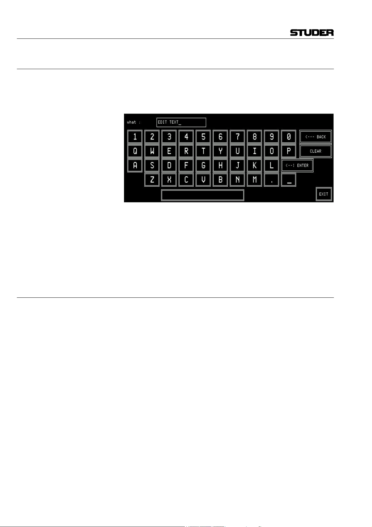
On-Air 2000 Digital Mixing Console
5.6.2 Save a snapshot to memory
Saving a snapshot is done by touching a snapshot key, followed by SAVE
MEM. The keyboard page appears where the snapshot name can be entered
or edited (max. 20 characters). If the existing name is to be kept, just touch
the <--¦ ENTER key.
CLEAR is used to clear the EDIT TEXT field for entering a new name with
the keyboard. <--- BACK is used to delete one character to the left of
the cursor. EXIT is used to leave the keyboard page without saving the new
name. When pressing <--¦ ENTER, the keyboard page is left and the
snapshot data are saved.
Note: Global snapshots can be saved by the system administrator only. Logged-in
users can save their private snapshots only.
5.6.3 Delete a snapshot from memory
When saving a snapshot the previously stored snapshot data are overwritten.
A snapshot can be deleted, too, without overwriting it with new data.
For deleting a snapshot from the console's internal flash memory, the desired
snapshot has to be selected. The selected key is highlighted. After touching
the DELETE MEM key a dialog box appears. If it is confirmed, the snapshot will be definitively removed from the memory and the name within the
selected key is cleared.
E5/8 Master functions SW V3.0 Date printed: 05.10.99
Page 48

5.7 Microphone settings
A microphone setting is a set of equalizer and gain parameters (EQ, gain,
phase, phantom power) for a single microphone channel. Thus, every DJ or
announcer can store his preferred microphone settings and recall them at any
time. Up to four private microphone settings for each user (max. 20 users),
and up to ten global microphone settings can be stored in the console's flash
memory; additional microphone settings can be stored on a PC-card as well
(refer to section 5.8).
Microphone settings can be named, as the snapshots; these names are displayed on the two key columns in the center of the Mixer setup page.
5.7.1 Recall a microphone setting from memory
To recall a microphone setting from the console's internal flash memory,
first a microphone input channel has to be selected by pressing the MIXER
SETUP key, followed by the corresponding MIC SETTING key. The name
of the selected microphone setting is highlighted.
Then touch the RECALL FROM MEMORY key. The selected channel’s
parameters are immediately set to the values of the microphone setting.
Selection of another type of input (line or digital) is treated as an error and
will not be accepted by the system.
On-Air 2000 Digital Mixing Console
If the last modification was made on a microphone channel, this channel is
automatically selected and displayed in the top line of the mixer setup page.
If the user wants to change the input selection, he touches the label field of
the desired channel in the channel screen. The input being currently active
(A or B) of this channel is now selected and shown in the top line of the
mixer setup page.
Date printed: 05.10.99 SW V3.0 Master functions E5/9
Page 49

On-Air 2000 Digital Mixing Console
5.7.2 Save a microphone setting to memory
Creating a microphone setting means saving a set of equalizer and gain parameters for a single microphone channel under a given name into the console's internal flash memory. This is done by first selecting the microphone
channel to be stored, then touching a MIC SETTING key, followed by
SAVE MEM. The keyboard page appears where the microphone setting's
name can be edited. Any MIC SETTING key (also one of these which have
already been used and have a name assigned) can be selected. It will, however, be overwritten by the new mic setting.
Now a new name can be generated, or the already present name can be
overwritten or edited. When pressing <--¦ Enter, the microphone setting
data and its new name is saved.
5.7.3 Delete a microphone setting from memory
When saving a microphone setting the previously stored data are overwritten. A microphone setting can be deleted, too, without overwriting it with
new data.
For deleting a microphone setting from the console's internal flash memory,
the desired microphone setting has to be selected. The selected key is highlighted. After touching the DELETE MEM key, a dialog box will appear. If
it is confirmed, the microphone setting will be definitively removed from the
memory, and the text within the selected key is cleared.
E5/10 Master functions SW V3.0 Date printed: 05.10.99
Page 50

5.8 Using PC-cards
Snapshots and mic settings can also be saved to a PC-card and loading them
from the card into the console's flash memory. Using PC-cards, parameter
settings of a console can be copied to an other one, provided that both have
the same configuration.
A PCMCIA card with a capacity of 64 kB can hold about 20 snapshots. On
a 4 MB card, the complete console software and the configuration and parameter data of the console.
5.8.1 Load a snapshot/mic setting from PC-card
To load a snapshot or a microphone setting from a PC-card, LOAD FROM
CARD must be pressed. The following page will be displayed:
On-Air 2000 Digital Mixing Console
Snapshots or mic settings can only be loaded as long as there are sufficient
empty snapshots or mic settings available in the console's flash memory.
They can be selected for loading by scrolling with the corresponding << or
>> keys, followed by LOAD. After having loaded a snapshot or mic setting,
it is not automatically active, but it is just available in the Mixer Setup page
and must be recalled with RECALL FROM MEMORY, as described in
sections 5.6.1 and 5.7.1, respectively.
5.8.2 Save a snapshot/mic setting to PC-card
To save a snapshot or a mic setting to a PC-card, first a snapshot or a mic
setting must be selected in the Mixer Setup page. Then the SAVE CARD
key must be pressed. A keyboard appears for entering a file name (max. 8
characters), as described in sections 5.6.2 and 5.7.2 .
After confirmation with ENTER, the snapshot or the mic setting is saved on
the card.
If an empty file name is entered or EXIT is pressed, the action is cancelled
without saving anything to the PC-card.
Date printed: 05.10.99 SW V3.0 Master functions E5/11
Page 51

On-Air 2000 Digital Mixing Console
Exceptions: If the file name already exists on the PC-card, the action must be confirmed
before the file is overwritten.
If a user with an other password tries to store a file under an already existing file name which has not been given by him, he will not be able to overwrite this particular file (only the administrator is allowed to overwrite all
files).
If the card is full, a dialog box appears, telling that the file cannot be saved.
File name extensions: The three-character DOS file name extensions on the PC-card will be gener-
ated automatically. The relationship between the file name extension and the
file content is shown in the following table.
Data type File name extension
Global snapshot .gss
Private snapshot .pss
Global mic setting .mis
Private mic setting .mip
5.8.3 Delete a snapshot/mic setting from PC-card
To delete a snapshot or a mic setting from the PC-card, DELETE CARD
must be pressed. The following page is displayed:
A snapshot or a mic setting can be selected for deleting by scrolling with the
corresponding << or >> keys. The selected file and the snapshot or mic setting name which is contained in this file are displayed to the right of the << /
>> keys. When pressing DELETE, the file is deleted definitively; once deleted, the data cannot be recovered.
A user can only delete his own, private data from the card. The administrator, however, has access to all (global and private) files on the card. Depending on what selection the administrator has made in the Setup page, either only the global or only the private files are displayed for him.
The DELETE FROM PC-CARD page remains until either EXIT or one of
the main menu keys is touched.
E5/12 Master functions SW V3.0 Date printed: 05.10.99
Page 52

5.9 Administrator
5.9.1 Features
On-Air 2000 Digital Mixing Console
• No private snapshots for the administrator.
• The administrator has access to all private and global parameter settings.
• Only the administrator has access to the SYSTEM CONF. and USER
ADMIN. keys.
The administrator's Mixer Setup page is shown above. In this case all
SAVE, DELETE, RECALL, and LOAD actions correspond to global snapshots and mic settings.
When the administrator touches the PRIVATE key and selects one of the
users, he can modify her or his private settings (see section 5.9.2).
A normal user (which is not logged in as administrator) has only access to
global snapshots and mic settings and to her/his own private snapshots and
mic settings.
Summary: The displayed snapshots and mic settings depend on the type of user logged-
in to the console.
A user which has entered no password can access private settings, too; these
will, however, not be password protected and can be overwritten by any
other user not being logged-in to the console.
Global parameter settings can be recalled by any user but modified by the
administrator only.
Access rights:
Global
snapshots
Administrator read/write read/write --- ---
Administrator working with a
selected user (see 5.9.2)
Logged-on user or default user read read read/write read/write
read/write read/write read/write read/write
Global mic
settings
Private
snapshots
Private mic
settings
Number of parameter sets:
Global mic settings 10 1 10
Private mic settings 4 per user 20 80
Date printed: 05.10.99 SW V3.0 Master functions E5/13
Data type Number Multiplied by Total data records
Global snapshots 5 1 5
Private snapshots 4 per user 20 80
Page 53

On-Air 2000 Digital Mixing Console
5.9.2 Administrator selection of snapshots/mic settings
The administrator can display and modify the private snapshot and mic setting data. After selecting PRIVATE in the SNAPSHOTS/MIC SETTING
page, the second rotary encoder from the left (the one below the users name
label) allows to select the user's name. In this mode the administrator can
LOAD, RECALL, SAVE, or DELETE all of the data being displayed.
This feature has been implemented in order to enable the setting of parameters in a private snapshot or mic setting to which the particular normal user
has no access. All actions such as RECALL FROM MEMORY, SAVE
MEM, DELETE MEM, LOAD FROM CARD, SAVE CARD, and
DELETE CARD concern the selected user's data. All other actions on the
console cannot be affected.
5.9.3 Users with and without a password
When a normal user enters the Mixer Setup page before logging-in (which
means he is treated as default user), he works with the default user's data.
He can LOAD, RECALL, SAVE, or DELETE all of the default user's data
in the console's memory or on the PC-card. These data can, however, be
used, saved, overwritten, or deleted by any other user, who is not logged-in
as well.
The Mixer Setup page offers a PRIVATE key to the left of the GLOBAL
key, allowing the user – after he has logged-in – to access his own, protected
private snapshots and mic settings.
Should the user have access permission to the system configuration, then the
SYSTEM CONF. key would be displayed, too.
E5/14 Master functions SW V3.0 Date printed: 05.10.99
Page 54

On-Air 2000 Digital Mixing Console
A user can decide to work with the global data although he is already
logged-in. If the GLOBAL key is pressed, the Mixer Setup page will look as
shown below, where he can recall (but cannot modify) the global snapshots
and mic settings. If the user has access permission to the system configuration, the SYSTEM CONF. key would be displayed, too.
5.10 User administration
USER ADMINISTRATION is only accessible by the administrator. Refer
to section 11 for details on how to set up function access permission and
new user accounts.
5.11 System configuration
System configuration is a separate function group which can be accessed
only by the administrator or by users having access permission. It is separately described in detail (refer to section 12).
Date printed: 05.10.99 SW V3.0 Master functions E5/15
Page 55

On-Air 2000 Digital Mixing Console
5.12 Watch and stopwatch
The watch and stopwatch functions are continuously displayed on the righthand side of the central screen.
The term “watch” refers to the time of day in analog and digital format, the
day of the week and date in an abbreviated format.
The term “stopwatch” refers to both the fader and the user stopwatches. The
fader stopwatch measures the time the most recently used channel fader has
been opened. The user stopwatch works like a normal stopwatch with
START/STOP and RESET keys located directly below the display screen.
Below, the HOME page with the watch and stopwatch displays and functions is shown.
5.12.1 Watch
The watch gives a permanent time, day of week, and date display. The normal time reference is an internal, battery-buffered real-time clock (RTC).
The RTC continues to run even when the console is switched off. Therefore
it is unnecessary to set the watch at power-up. The RTC can also by synchronized by an optional TimeSync Module connected to the control module
bus. If synchronization is established, the top right corner of the central
screen shows an “S” (sync OK).
Changes to the internal time reference and the time and date format can be
made by the administrator on the TIME page (MIXER SETUP, SYSTEM
CONFIG., TIME). For details, refer to section 12.2.5.
Both time and date can be displayed in two formats, as shown below:
Time format Digital time indication
12:00 p.m. 12 hour time format
24:00 24 hour time format
Date format Example
DD.MMM.YY MO 20.MAR99
MMM-DD-YY MO MAR-20-99
E5/16 Master functions SW V3.0 Date printed: 05.10.99
Page 56

5.12.2 Fader stopwatch
Note: If more than one channel have caused the fader stopwatch to restart, only
5.12.3 User stopwatch
On-Air 2000 Digital Mixing Console
The upper of the two stopwatches is called the fader stopwatch. It always
restarts at 00:00:00 when a new input channel is activated (e.g. channel ON,
fader open, and output bus selected). In other words, it displays the elapsed
time of the last channel opened.
This function can be enabled or disabled for any desired channels via the
MIXER SETUP/SYSTEM CONFIG./INPUT menu, item TIMER START
YES/NO.
The counter stops when the channel which has started the stopwatch is
switched OFF, or its fader is closed.
the last channel’s time is displayed.
The user stopwatch is located just below the fader stopwatch. It is controlled
by two keys on the console’s surface located below the digits of the display.
One key starts and stops the timer, the other resets the timer.
Key Label Description
START
STOP
RESET
START Start timer if stopped
STOP Stop timer if running
RESET
Reset timer regardless
whether stopped or running
Date printed: 05.10.99 SW V3.0 Master functions E5/17
Page 57

On-Air 2000 Digital Mixing Console
5.13 Master fader for PGM and REC outputs
Starting with SW V3.0, any of the 24 faders – i.e. even faders the number of
which is higher than the number of channels the console is configured for –
can be configured as master fader(s) for the program and/or the record bus.
This selection is performed with the two leftmost rotary encoders located
below the PGM MASTER and REC MASTER fields (in the MASTER
FADER ASSIGNMENT section on the COMMON SETTINGS page),
followed by touching APPLY.
The corresponding input channel can still be used, however without control
possibilities from the operating surface (i.e., only the external MUTE and
Monitora control is available). In such a case, this channel may be used as a
talkback mic input channel; please note that the TB SOURCE parameter of
this input must then be set to “CR” in the INPUT CONFIG. page.
If only fixed PGM MASTER and/or REC MASTER output levels are required, it is also possible to set them once and switch back to the normal
channel control afterwards – just by selecting “NONE” in the PGM
MASTER and REC MASTER fields on the COMMON SETTINGS page.
Important: When re-establishing standard console operation, please make sure that
the master levels are set back to 0 dB.
Specifications: • In the audio path, the master fader(s) is/are located before the insert points
(also refer to the block diagram in section 1);
• No ON/OFF function is available for the master busses;
• PFL function is available;
• Overload indication is available;
• Master level can be controlled by Monitora extended commands;
• Signaling (ON-AIR, CR-MIC, and STUDIO-MIC) and CR/Studio
CUT/DIM as well as some restrictions of the graphical user interface consider the master faders.
COMMON SETTINGS page:
Corresponding channel screen:
E5/18 Master functions SW V3.0 Date printed: 05.10.99
Page 58

6 LEVEL METERS
On-Air 2000 Digital Mixing Console
On-Air 2000 mixing consoles can be equipped with one or two stereo level
meters, according to the customer’s specification.
It is configurable for both meters which signal they display; the following
sources can be selected in the configuration menu and are available in analog and digital (AES/EBU) form for the meters:
Meter 1 Meter 2 Source
X X CR MONITOR
X X PROGRAM
X X RECORD
X X AUX 1
X X AUX 2
X AUDIT
X N–1 A
For configuration details refer to section 12.2.4.
6.1 Standard level meters
The following level meters can be installed as standard:
Digital
Analog
Dual bargraph, PPM, with correlator RTW 11519D
Stereo display, dual PM, with correlator RTW 1069
Dual bargraph, PPM, with correlator RTW 1119E
Dual bargraph, PPM Studer 1.913.111
Dual bargraph, VU Studer 1.913.112
Dual 30-LED, PPM Studer 1.913.105
Dual 30-LED, VU Studer 1.913.106
Correlator, 30-LED Studer 1.913.109
Correlator, 30-LED, switchable to meter 1 and 2 Studer 1.913.100
Date printed: 05.10.99 Level meters E6/1
Page 59

7 MONITORING
7.1 Control room monitoring
The CR monitoring source selector has 10 keys to select one out of six internal and 4 analog external sources. The key of the selected source is illuminated.
The F1...F5 keys can act as additional source selectors, provided that the
optional Monitor Extension 1 is installed and configured accordingly.
F1...F5 then select two additional digital and three additional analog external sources. The functionality of these keys can be configured in the Monitor Expander screen.
Key Source Description
AUX 2
AUX 1
AUDIT
S REC
S PGM
PFL
On-Air 2000 Digital Mixing Console
Auxiliary 1
Auxiliary 2
Audition
Record output
Program output
(on-air)
PFL PFL sum. PFL is illuminated if selected.
General purpose output bus. AUX2 is illuminated
if selected.
General purpose output bus. AUX1 is illuminated
if selected.
General purpose output bus. The input channels
to the audition bus are configurable. AUDIT is
illuminated if selected.
Output signal of the record master output. ΣREC
is illuminated if selected.
Output signal of the on-air master output. ΣPGM
is illuminated if selected.
EXT 3
EXT 2
EXT 1
OFF AIR
F 5
F 4
F 3
F 2
F 1
External 3
External 2
External 1
Off-air
External 8*
External 7*
External 6*
External 5*
External 4*
General purpose analog stereo input signal.
EXT3 is illuminated if selected.
General purpose analog stereo input signal.
EXT2 is illuminated if selected.
General purpose analog stereo input signal.
EXT1 is illuminated if selected.
General purpose analog stereo input signal (e.g.
tuner). OFF AIR is illuminated if selected.
General purpose digital (AES/EBU) stereo input
signal. F5 is illuminated if selected.
General purpose digital (AES/EBU) stereo input
signal. F4 is illuminated if selected.
General purpose analog stereo input signal.
F3 is illuminated if selected.
General purpose analog stereo input signal.
F2 is illuminated if selected.
General purpose analog stereo input signal.
F1 is illuminated if selected.
* see Monitor Expander module configuration, section 12.2.11.
Date printed: 05.10.99 SW V3.0 Monitoring E7/1
Page 60

On-Air 2000 Digital Mixing Console
Two additional keys are used to control the monitoring loudspeakers in the
control room. The functions of these keys are described in the table below.
A volume control knob (MON ) is used to set the level sent to the CR
monitor speakers.
As long as one of the microphones in the control room (DJ or guest microphone) is on, the monitor speakers are muted. In this case the CUT key is
illuminated.
If the monitoring source is AUDIT (audition bus), the monitor speakers are
either dimmed (DIM key illuminated), muted (CUT key illuminated), or not
affected at all, according to the configuration (see section 12.2.2 for details).
If talkback is active, the level of the monitor speaker is dimmed by 20 dB
and the DIM key is illuminated.
External CR DIM: On from SW V2.02, an additional control input has been implemented, al-
lowing to reduce the level of the CR monitor speakers by 20 dB by an external signal (see section 15.12 for details).
Key Function Description
The output level to the CR monitor loudspeakers
DIM
CUT
–20 dB
Mute
is reduced by 20 dB. DIM is illuminated if selected.
The output to the CR monitor loudspeakers is
muted. CUT is illuminated if selected.
The signal on the PFL bus is reproduced by the console’s built-in speakers
(mono). The same speakers are used for talkback. The volume is adjusted
with the PFL/TB potentiometer.
For monitoring purposes, a headphones connector is provided below the
hand rest of the central console part. Three keys allow different monitoring
modes, as described below:
Key Function Description
PFL
MON
PFL
MON
PFL
PFL/CR monitor
CR monitor
The headphones signal is the stereo PFL signal.
PFL is illuminated if selected.
The left headphones signal is the mono PFL
signal, while the right headphones signal is the
mono CR signal as selected by the monitor
source selector. If no PFL is selected, the headphones signal is the stereo CR signal as selected. MON/PFL is illuminated if selected.
The headphones signal is the same stereo signals as selected by the source selector for the
monitor speaker. MON is illuminated if selected.
The CUT and DIM keys have no influence on the headphones signal. The
headphones output is not muted if one of the control room microphones is
on. The incoming talkback signal from the studio is mixed to the headphones
output. For improved intellegibility, the monitoring signal is attenuated by
20 dB.
E7/2 Monitoring SW V3.0 Date printed: 05.10.99
Page 61

On-Air 2000 Digital Mixing Console
The PFL to MONITOR function feeds the PFL signal to the monitor loudspeakers if PFL is selected on any channel. The normal monitoring signal is
muted until no more PFL keys are active.
Key Function Description
The PFL signal is routed to the monitor speakers
PFL
MON
PFL to
MONITOR
A volume control knob (PHONES ) adjusts the headphones listening level.
if PFL on any channel is active. If no PFL is
selected, the monitoring signal is the stereo CR
signal as selected. PFL > MON is illuminated if
selected.
Date printed: 05.10.99 SW V3.0 Monitoring E7/3
Page 62

On-Air 2000 Digital Mixing Console
7.2 Studio monitoring
The built-in studio monitoring functions are based on a touch-screen menu
on the control screen. The STUDIO MONITORING SOURCE selector
page allows one of six sources to be selected for routing to the studio speakers and headphones.
The table below lists the available sources.
Label Function Description
PROGRAM
AUX 1 AUX 1
AUX 2 AUX 2
PFL PFL PFL sum. PFL is highlighted if selected.
OFF AIR Off-air
EXTERN External
Program output
(on-air)
Output signal to the transmitter. PROGRAM is
highlighted if selected.
General purpose output sum. AUX1 is highlighted
if selected.
General purpose output sum. AUX2 is highlighted
if selected.
General purpose input signal, usually from receiver. OFF AIR is highlighted if selected.
General purpose input signal. EXTERN is highlighted if selected.
As soon as one of the keys is pressed, the corresponding signal is routed to
the studio, and the key is illuminated.
The monitoring source selection can be controlled from the studio via external pushbuttons thanks to the parallel interface. The monitor speaker and
headphones levels can independently controlled by two potentiometers located in the studio.
The studio monitoring speakers are muted if one of the studio microphones
is on. The headphones are not muted in this case.
During talkback from the CR to the studio, the volume for the studio speakers is reduced by 20 dB. The talkback signal from the CR to the studio is
not reduced and has therefore the normal listening level on both the studio
monitor speakers and the studio monitor headphones.
E7/4 Monitoring SW V3.0 Date printed: 05.10.99
Page 63

7.3 Talkback
On-Air 2000 Digital Mixing Console
There is a choice among five talkback destinations from the DJ microphone.
A key is assigned for each destination as can be seen in the table below.
Key Function Description
N–1 B
N–1 A
AUX 2
AUX 1
STUDIO
TB to Tele-
phone 2
TB to Tele-
phone 1
TB to
Auxiliary 2
TB to
Auxiliary 1
TB to Studio
The DJ microphone usually is the source for talkback from the CR.
For mixing consoles with less than 24 channels, a separate talkback microphone is optionally available, including preamplifier, limiter, and A/D converter. Its main application is in production and editing control rooms where
no DJ microphone is required; for details, refer to section 15.17.
The connection between DJ mic and Cleanfeed B
(N–1B, e.g. telephone 2) is established for as
long as this key is pressed.
The connection between DJ mic and Cleanfeed A
(N–1A, e.g. telephone 1) is established for as
long as this key is pressed.
The connection between DJ mic and Auxiliary 2
is established for as long as this key is pressed.
The connection between DJ mic and Auxiliary 1
is established for as long as this key is pressed.
The connection between DJ mic and the Studio is
established for as long as this key is pressed.
The parallel studio interface allows the connection of three pushbuttons for
talkback destination selection. The possible destinations are: CR, Cleanfeed
1 (N-1 A), and Cleanfeed 2 (N-1 B). For talkback from the studio the studio
microphones are used.
The console’s built-in PFL/TB loudspeaker and the headphones are used for
talkback listening in the CR, while in the studio the monitoring speakers and
the headphones are used.
Any of the function keys F1...F5 can be configured as additional talkback
target keys. This allows, together with the optional Monitor extension, e.g.
talkback to the audition bus. This bus could therefore be used as a third
cleanfeed bus (N–1 C).
7.3.1 Additional talkback functions
The new Monitoring Module w. TB return 1.942.180.20 as well as the new
Extended Monitoring Module w. TB return 1.942.181.20 both provide an
additional TB line input (electronically balanced, on the “STUDIO
MONITOR AUDIO” connector) as well as additional CR and studio control
inputs (on the “EXT PFL CTRL” connector). Please refer to the pin assignment tables and the connection diagram in section 15.12.
Date printed: 05.10.99 SW V3.0 Monitoring E7/5
Page 64

On-Air 2000 Digital Mixing Console
7.3.2 Talkback settings
Starting with SW V3.0, talkback and signaling can be configured independently. The “SIGN.” setting (formerly labeled “MIC LOCATION”) in the
INPUT CONFIG. page is used only for signaling (red light) and monitoring
(cut and dim).
The additional “TB SOURCE” parameter in the INPUT CONFIG. page
sets the assignment of the input to the TB bus (NONE, from CR, or from
Studio).
During talkback from the Studio, the studio speakers are dimmed only if at
least one input is configured as “SIGN.” = STUDIO and “TB SOURCE” =
STUDIO. The same applies for talkback from the control room.
Note: Configuration of talkback and signaling is also possible for analog or digital
line inputs, as shown by the following screenshots.
E7/6 Monitoring SW V3.0 Date printed: 05.10.99
Page 65

7.4 External PFL
On-Air 2000 Digital Mixing Console
The On-Air 2000 provides an external PFL audio input. If the EXT PFL
key is pressed, the key is illuminated, and the signal at the EXT PFL input is
routed to the PFL bus. A control output is activated if EXT PFL is active.
In addition, the EXT PFL function can be activated by a dedicated control
input (refer to section 15.12).
With this feature, the On-Air 2000 is well-suited for the cooperation with a
CAB system. These systems need a separate PFL input activated by the
system.
Key Function Description
Switches the EXT PFL OUT control output on
EXT
PFL
External PFL
and off, and routes the EXT PFL audio input
signal to the PFL bus. The key is illuminated if
active, or if a control signal is applied to the EXT
PFL input.
Date printed: 05.10.99 SW V3.0 Monitoring E7/7
Page 66

8 SIGNALING
On-Air 2000 Digital Mixing Console
For control room and studio, signaling is provided by means of opencollector outputs (9-pin D-type connector on the Monitoring module; for
connection details, see section 15.12).
One output is available for each of the following statuses:
• Control Room microphone is on-air,
• Studio microphone is on-air, and
• Any signal from the console is on-air (i.e., a fader is open, this channel's ON
pushbutton is active, and its signal is routed to the PROGRAM and/or the
RECORD bus).
The CR-MIC and STUDIO-MIC indicators in the central operating section
of the console are illuminated when the corresponding control output is active.
SIGN. Output Active if:
CR MIC OUT At least one input of a CR or DJ microphone is active (channel ON,
fader open, assigned to program or record bus).
STUDIO MIC OUT At least one input of a studio microphone is active (channel ON,
fader open, assigned to program or record bus).
PGM OUT Depending on ON-AIR INDICATION condition selected on the
COMMON SETTINGS page:
• ΣPROGRAM AND ΣRECORD – at least one channel is active
(channel ON, fader open, assigned to program or record bus).
• ΣPROGRAM – at least one channel is active (channel ON,
fader open, assigned to program bus).
• ΣRECORD – at least one channel is active (channel ON, fader
open, assigned to record bus).
The ON AIR INDICATION condition for the PGM OUT control signal can
be set in the COMMON SETTINGS page (which is reached by pressing
MIXER SETUP followed by COMMON), if access permission is available.
An additional ON AIR IN opto-coupler input on the SIGN. connector can
be used for illuminating the ON-AIR indicator in the central operating section of the console.
Note: For information on the MASTER FADER ASSIGNMENT field, please
refer to section 5.13.
Date printed: 05.10.99 SW V3.0 Signaling E8/1
Page 67

9 MACHINE CONTROL
The On-Air 2000 provides different control inputs and outputs. These can
be used e.g. for switching a channel on and off, or for starting, stopping, and
cueing of the connected source unit (as CD players, tape recorders, or a
CAB system).
Each audio input holds two control outputs and one control input on D-type
connectors. The signals are:
• CTRL OUT 1 (normally used for fader start, but configurable for other
functions; see section 9.2.1)
• CTRL OUT 2 (configurable functions see section 9.2.2)
• CTRL IN (configurable functions see section 9.3.1)
The status of the output signals depends on the control elements of the
channel strip (keys 1...3, fader, input selection, output routing), as well as
on the console configuration.
Each channel consists of either two (A/B input module) or six (hex input
module) audio inputs. Each audio input has its own control input and two
control outputs allowing to control every external source separately.
On-Air 2000 Digital Mixing Console
Source
label
OVL
Key 1
PFL
LED 1
10
0
10
20
30
40
50
60
∞
ON
Fader
Key 2
LED 2
Fader
start
OFF
Date printed: 05.10.99 SW V3.0 Machine control E9/1
Key 3
LED 3
Page 68

On-Air 2000 Digital Mixing Console
9.1 Keys and LEDs
Key 1/LED 1 The first key is always used to activate/deactivate the PFL function; if ac-
tive, LED 1 is illuminated.
The PFL function can affect the CTRL OUT1 and/or CTRL OUT2 control
signals, depending on the configuration. This configuration is performed in
the center section of the INPUT CONFIG. page and is identical for all types
of input modules.
Key 2/LED 2 The second key is used either to switch the channel ON or to toggle the
channel ON/OFF, depending on the configuration of key 3. This function affects the CTRL OUT1 control signal. LED 2 always indicates the channel's
ON/OFF status.
Key 3/LED 3 The functionality of the third key depends on the console configuration. It
can act as channel OFF key or as a LOCATE function. The key 3 functionality is set in the COMMON SETTINGS page:
Console configuration (valid for all channels):
Key 3 (“OFF”) function Key 2 (“ON”) function
(Channel) OFF (Channel) ON
LOCATE (Channel) ON/OFF
LOCATE (Channel) ON *
Channel ON/OFF affects the CTRL OUT1 control signal of the selected
input, and the locate function defines the status of the CTRL OUT2 control
signal of the selected input.
* This additional configuration possibility has been introduced with SW V3.0;
to protect a channel from being switched off inadvertently, the OFF function
can be disabled. This setting is performed in the COMMON SETTINGS
page; it is valid for all channels of the console simultaneously.
E9/2 Machine control SW V3.0 Date printed: 05.10.99
Page 69

On-Air 2000 Digital Mixing Console
Note: If this setting is selected, no channel can be switched off by pressing a key –
therefore, either closing the fader must do, or an external pushbutton per
channel has to be added. For this purpose, a CTRL IN control input per
channel is provided; please refer to section 9.3.1. Select the option “CTRL.
IN – EXT. ON/OFF” in the INPUT CONFIG. page.
LED 3 is illuminated if an external device indicates ready status using the
CTRL IN input signal of the selected input, or if the CAB system indicates
“ready for playback” using the serial remote interface
(SET_FADER_START*FaderNr).
Date printed: 05.10.99 SW V3.0 Machine control E9/3
Page 70

On-Air 2000 Digital Mixing Console
9.2 Control outputs
9.2.1 CTRL OUT1
This output is normally used to start external devices, such as CD players or
a CAB system, to play the next track. On the INPUT CONFIG. page (see
section 9.1), other functions can be assigned individually for each audio in-
put.
CTRL OUT1 mode CTRL OUT1 signal
PFL/ON & FADER
Input configuration (for each channel individually):
NOT ACTIVE Output always open (inactive).
ON & FADER
ON LAMP
Active if ON key is pressed and fader is open (standard fader start
function).
Active if either PFL key is pressed (independent of fader position),
of if ON key is pressed and fader is open (fader start function,
causing the source to be started as well when PFL key is pressed).
Active if channel is ON; used as acknowledgement if the channel
is remotely controlled.
9.2.2 CTRL OUT2
This output can be used to re-park an external device, such as a CD player,
after cueing, or for signaling, or as an acknowledgement for ON status. It
can be configured individually for each input in the INPUT CONFIG. page
(see section 9.1).
Input configuration (for each channel individually):
CTRL OUT2 mode CTRL OUT2 signal
NOT ACTIVE Output always open (inactive).
Active if key 3 (“OFF”, configured as LOCATE key) is pressed
LOCATE KEY
PREVIEW
LOCATE PFL KEY
LOCATE PFL /
LOC KEY
ATTENTION
ON LAMP
while the channel is closed (fader closed or channel OFF). Using
this function, a source which has been pre-listened before can be
reset to the start point.
Active as long as key 1 (“PFL”) is pressed while the channel is
closed (fader closed or channel OFF). Using this function, a source
can be started for pre-listening.
Active for 0.2 s when key 1 (“PFL”) is switched off while the channel is closed (fader closed or channel OFF). Using this function, a
source can be given a locate command to return to the start point.
Combination of LOCATE KEY and LOCATE PFL KEY functions:
• Output is active for 0.2 s when key 1 (“PFL”) is switched off
while the channel is closed (fader closed or channel OFF).
Using this function, a source can be given a locate command
to return to the start point.
• Output is active if key 3 (“OFF”, configured as LOCATE key)
is pressed while the channel is closed (fader closed or channel OFF). Using this function, a source which has been pre-
listened before can be reset to the start point.
Active as long as key 3 (“OFF”, configured as LOCATE key) is
pressed; can be used for “ready” signaling.
Active if channel is ON; used as acknowledgement if the channel
is remotely controlled.
E9/4 Machine control SW V3.0 Date printed: 05.10.99
Page 71

9.3 Control inputs
9.3.1 CTRL IN
Note: An optional control interface (1.942.802) can be used for the following
On-Air 2000 Digital Mixing Console
A CTRL IN control input is available for each audio input. This input'sfunction can be selected in the INPUT CONFIG. page (see section 9.1).
Input configuration (for each channel individually):
CTRL IN mode CTRL IN signal
NOT ACTIVE No function (input signal is ignored)
READY Key 3 (“OFF”) is illuminated as long as CTRL IN is active
EXT. MUTE Channel is muted as long as CTRL IN is active (e.g. cough key)
EXT. ON/OFF
functions:
• Electrical isolation between CTRL OUT and the connected source (relay
with make contact);
• Conversion from the continuous fader start signal to electrically isolated
start and stop pulses;
• Remote control of a channel using separate ON and OFF keys, logically
linked with the ON LAMP signal. The ON and OFF keys in the console remain functional;
• Remote control of a channel through a CAB system which gives a continuous signal as long as a channel must be on, logically linked with the ON
LAMP signal. The external command is overridden by the ON and OFF
keys in the console.
Toggles the channel ON/OFF; used e.g. for ON/OFF button on
speaker’s desk, or for remote control through CAB system
9.3.2 EXTERN PFL input
An external PFL control input is available on the monitoring module of the
console (refer to section 15.12). It allows e.g. the EXTERN PFL prelistening audio path to be opened by a CAB system.
Date printed: 05.10.99 SW V3.0 Machine control E9/5
Page 72

On-Air 2000 Digital Mixing Console
On-Air 2000
D730/D731 CD player
9.4 CTRL OUT1/2 & CTRL IN application examples
Application
Fader start/stop with:
Fader open/close, or channel ON/OFF
Fader start/stop with:
Fader open/close, or channel ON/OFF, or
PFL ON/OFF
Review function of Studer D730/D731:
pre-listening with PFL and subsequent locate
to the last cue address. Afterwards: PLAY
with fader start; see Notes 1 and 2
Pre-listening with PFL and subsequent locate
to the start; console sends an 0.2 s locate
pulse on CTRL OUT2. Afterwards: PLAY
with fader start; see Note 1
Manual locate to the start, using
OFF/LOCATE key 3; see Note 1
Pre-listening with PFL and subsequent locate
to the start. Manual locate also available;
see Note 1
Control of any external singal with key 3
(“OFF”)
Reflects the ON lamp status to CTRL OUT1 ON LAMP — — CTRL OUT1 –> any control input
Reflects the ON lamp status to CTRL OUT2 — ON LAMP — CTRL OUT2 –> any control input
Note 1: Function is available only if the corresponding console channel is not active; “channel active” = fader open and channel ON and
channel assigned to PGM or REC bus.
Note 2: D730/D731 configuration checksum example, suited for this function: 4050631164470. For more information on this subject,
please refer to the D730/D731 operating instructions manual, order no. 10.27.1672
Note 3: Combination of different applications is possible if allowed by the CTRL OUT1/2 wiring.
Configuration
CTRL OUT1
ON & FADER — —
PFL / ON &
FADER
ON & FADER PREVIEW —
PFL / ON &
FADER
— LOCATE KEY LOCATE
PFL / ON &
FADER
— ATTENTION LOCATE CTRL OUT2 –> any control input
Configuration
CTRL OUT2
— —
LOCATE PFL
KEY
LOCATE PFL /
LOC KEY
Configuration of
key 3
(“OFF”/LOCATE)
—
LOCATE
Connection(s) On-Air 2000 –>
controlled source (e.g.
CD player, cart/tape recorder
CTRL OUT1 –> remote control
input “fader start”
CTRL OUT1 –> remote control
input “fader start”
CTRL OUT2 –> Studer D730/
D731, remote control input
“SR_REVIEW”; see fig. a)
CTRL OUT1 –> remote control
input “fader start”, CTRL OUT2
–> remote control input “locate”;
see fig. b)
CTRL OUT2 –> remote control
input “locate”; see fig. b)
CTRL OUT1 –> remote control
input “fader start”; CTRL OUT2
–> remote control input “locate”;
see fig. b)
a)
CTRL IN
CTRL OUT1
BR_PAUSE
FAD1
SR_REVIEWCTRL OUT2
On-Air 2000 D730/D731 CD player
b)
CTRL IN
CTRL OUT1
E9/6 Machine control SW V3.0 Date printed: 05.10.99
BR_PAUSE
FAD1
SR_LOCATECTRL OUT2
Page 73

10 AUTOMATION
10.1 Introduction
Studer Digimedia system: Information on how to connect and operate the On-Air 2000 mixing console
On-Air 2000 Digital Mixing Console
On-Air 2000 has no built-in automation but supports external CAB (computer-assisted broadcast) systems. With software version V2.0, also a serial
interface (RS232/RS422/RS485) can be used to communicate with the
CAB.
with a Digimedia CAB system is given in the current Digimedia operating
instructions.
The serial interface protocol is based on the “Schnittstellen Spezifikationen
Regiepult” of DAS (Digitale Steuerungs- und Automationstechnik, Thomas
Volgmann) furthermore called [MONPROT], which was defined by VCS
and Siemens.
It was not the target to implement the complete [MONPROT]. The implementation in the On-Air 2000 is rather a subset of [MONPROT] to allow
for the applications described in section 10.3.
For detailed information on the telegrams implemented in the On-Air
2000, please refer to the “Communication Protocol for Broadcast Automation” document [BCACOM] (available on request).
Date printed: 05.10.99 Automation E10/1
Page 74

On-Air 2000 Digital Mixing System
10.2 Features of the On-Air 2000 CAB support
Control
CD changer CD changer
[BCACOM]
Jingle 2
Jingle 1
HDD 2
HDD 1
News 1
News 2
Fader A Fader B Jingle 1 Jingle 2
On-Air console
• Serial communication interface:
Serial RS232/RS422/RS485 standard communication interface based on
[MONPROT].
• 2 x 12 character text display per channel.
• Music and speech output:
The CAB can control the output assignment (program/record bus) of the
currently selected input of a channel.
• 6 × 6 input routing:
The input selector of the On-Air 2000 provides an input routing, as each
input can select between 2 or 6 input lines. This leads to a maximum matrix
size of 6 × 6 inputs.
The On-Air 2000 does not support:
• Motor faders; instead, an auto take-over mode is implemented, see section
10.3.5.
• Fader routing; some consoles allow for a routing between input lines and
sources (“Quellname”) as well as for an assignment of a source (“Quellname”) to any fader (“Fadernummer”). In contrast to the suggestion of
[MONPROT], the On-Air 2000's implementation does not allow the faders
to be routed to any source.
E10/2 Automation Date printed: 05.10.99
Page 75

On-Air 2000 Digital Mixing Console
1
SAS 1
1
The concept as suggested by [MONPROT]
2 3 n
Switching matrix
SAS 2 SAS n CD 1 CD 2 HSR 1
2 n n+1 n+2 m
...
...
...
Input line
Mixing console
Source name
Fader no.
Date printed: 05.10.99 Automation E10/3
Page 76

On-Air 2000 Digital Mixing System
Input line F
10.3 Application handling
10.3.1 Configuration for automation control
Channels must be assigned to the automation system in the configuration in
order to be controlled by an external CAB system. The AUTOMATION
CONFIG. page is reached from the SYSTEM CONFIG. page:
10.3.2 Routing
The AUTOMATION CONFIG. page allows each channel to be assigned to
the CAB system.
As the hex input module allows selection of one input out of six, a 6 × 6
input routing is possible with six hex input modules (max. four hex modules
are allowed for a 24-channel console, and six hex modules for 18-, 12-, and
6-channel consoles).
Input line E
Input line D
Input line C
Input line B
Input line A
Fader 1 Fader 2 Fader 6
On-Air console
6 x 6 input routing with the On-Air 2000
E10/4 Automation Date printed: 05.10.99
Page 77

On-Air 2000 Digital Mixing Console
Source Selection The CAB selects a source (SELECT_SOURCE*Name command) by its
name (input name as configured in Input Configuration page within the OnAir 2000). On receipt of such a command, the On-Air 2000 looks for a
channel providing an input signal, the input name of which matches the first
eight characters of the desired name, converted into upper case.
First it checks if any channel is already selected providing a signal with this
name. If not, it looks for all channels not yet selected by the CAB providing
a signal with this name on one of its inputs. If found, the On-Air 2000 selects this input (A...F).
After that, this channel's number is communicated by the console to the
CAB (SOURCE_SELECTED*FaderNr) as a handle for subsequent operations.
A channel can be selected by the CAB (SELECT_SOURCE), if the following conditions are met:
• It must be assigned to be controlled by CAB (YES) in the Automation Config. page, and
• The input module must be present.
After a channel is selected by the CAB, its behaviour changes as follows:
• Indication of “ON-AIR” or “NEXT” within input selector field;
• It accepts channel-related commands as “SET_FADER_LEVEL* FaderNr”
telegram;
• It can indicate “display2” text from “SET_FADER_DISPLAY_2
*FaderNr” telegram within the source label field;
• It sends “FADERSTATUS*FaderNr, ...” to the CAB;
• It does not (de-)activate PFL on PFL key pressure, as PFL can be
(de-)activated by the “SET_PRELISTEN_ON” or “SET_PRELISTEN_OFF” telegrams only.
If an input module is removed during operation, a previously selected channel will automatically be deselected.
All source selections are lost after power-off.
Input Routing With “SET_SAS_INPUTROUTING* FaderNr”, the CAB can control the
input selector of a channel.
Using “SET_SAS_INPUTROUTING* FaderNr” does not deselect a previously selected source.
Date printed: 05.10.99 Automation E10/5
Page 78

On-Air 2000 Digital Mixing System
10.3.3 Communication time-out
Every 10 seconds, the On-Air 2000 sends “GET_DEVSTATUS” to the
CAB. If after 30 seconds no valid telegram is received from the CAB, the
On-Air 2000 assumpes that the communication is interrupted.
In this case it stops sending telegrams as “FADERSTATUS” to the CAB,
and the following actions are performed:
• All channels are deselected (refer to section 10.3.2);
• Source labels are re-drawn (name of selected input source will be indicated
again) which might have been overwritten (refer to section 10.3.10);
• A warning: “WARNG: XYZ - BCA - Communication lost” is displayed.
After the next/first telegram from CAB, communication will be re-established.
The information: “INFRM: XYZ - BCA - Communication established” is
generated.
The On-Air 2000 reports to a “GET_DEVSTATUS” request from the CAB
with “DEVSTATUS NO_ERROR”.
No error codes are defined.
10.3.4 Output selection
Using the “SET_ZI*FaderNr” telegram, the CAB is able to control the output assignment (program/record bus) of the currently selected input of any
channel. This allows to route speech to the program output, and music to the
record output.
10.3.5 Start a new title from schedule
In automatic mode, the CAB can start a new title automatically. It is also
possible to start new titles manually. In this case the operator opens the
fader (while the channel is already switched ON) or switches the desired
channel ON (while the fader is already open).
Automatic new title start: The CAB can control the console automatically. This automatic mode must
be activated from within the CAB and can, for example, be used for controlling a program during the night without any assistance.
If the CAB runs in automatic mode, it starts playback of the source and
sends the “SET_FADER_LEVEL*FaderNr” telegram with the desired level
and fade-in time. This will send a new audio level to the DSP, and switch
the channel ON in any case.
If a take ends, the CAB sends the “SET_FADER_LEVEL*FaderNr” telegram again, with a level of less than –70dB, and with the desired fade-out
time. This will send a new audio level to the DSP, and switch the channel
OFF in any case.
E10/6 Automation Date printed: 05.10.99
Page 79

On-Air 2000 Digital Mixing Console
If the CAB changes the audio level, the channel changes into auto take-over
mode. This means that the audio level (i.e. actual DSP level) and the fader
level (i.e. physical position of the fader knob) differ for more than a specified auto take-over window. If the fader is moved now, nothing will change
until the physical position of the fader knob is within the auto take-over
window. Then the auto take-over mode is left.
Auto take-over mode is indicated on the touch screen. The operator can
recognize the direction and distance to move the fader in order to leave auto
take-over mode.
The large arrow at the bottom (or top) indicates the direction the fader has
to be moved to leave auto take-over mode. The small horizontal line indicates the current physical fader position. It follows the fader position when
the fader knob is moved towards the two small arrows at the left and right
margin which indicate the current audio level.
Manual new title start: (Start a new title from schedule manually by DJ)
The “FADERSTATUS*FaderNr” telegram is send to the CAB to start the
next title from the schedule. It is used in the same way as the fader start
output signal in fader start mode “ON&FADER”. This means, the channel
must be ON and the fader must be open. “Fader open” is determined by
audio level (actual DSP volume) but not the physical fader position.
Example: Assuming that a channel is playing audio from CAB (audio level “open”)
and the fader is closed (fader level “closed”). This is the case after the CAB
has sent the telegram “SET_FADER_LEVEL* FaderNr”, i.e. auto takeover mode. If the operator now takes control of that channel by opening the
fader in order to leave auto take-over mode, the On-Air 2000 does not send
any “FADERSTATUS*FaderNr” telegram, as the audio level does not
change until auto take-over mode is left.
From the user's view, there exist two different methods to start new titles
manually:
• Fader A-B operation, and
• Fixed source/channel assignment.
The On-Air 2000 supports both methods, as in practice, you will find a
mixture of them. The selected method depends on the CAB, whether it uses
the input routing facility of the On-Air 2000 for real Fader A-B operation.
Date printed: 05.10.99 Automation E10/7
Page 80

On-Air 2000 Digital Mixing System
Fader A-B operation: In real A-B operation the operator does not care which fader to open to start
the next scheduled title. No matter which fader will be opened, the next title
is played from schedule.
In this case, the CAB system uses the “SET_SAS_INPUTROUTING
*FaderNr” command to change input routing before playback.
Fixed source/channel assignment: The next title is assigned to a channel by the “SELECT_SOURCE” com-
mand (refer to section 10.3.2). READY and NEXT indication is provided
within the channel strip. If more than one channel is ready, the fader of the
one indicated as next must be opened. Otherwise, one or more titles would
be skipped in schedule.
10.3.6 Next Indication
The CAB is able to indicate on which channel the next title from schedule
will be played (“SET_NEXT _BUTTON-LIGHT*FaderNr”). For that
channel, the source label will be highlighted, as it is done with the NEXT
function. In addition, the source selector field on the channel screen indicates
“NEXT” – but only if the channel is selected by CAB
(SOURCE_SELECTION). So the selection of an other input is inhibited
(refer to the figure above).
This way, it is easy for the user to find the next fader to be opened, particularly if the source/fader assignment is fixed (see section 10.3.5).
Only one channel can be the next (“the last wins”).
10.3.7 Indication of the currently playing input line
As the On-Air 2000 is not equipped with motor faders, a clear indication of
the channel currently “playing” is necessary.
Under the following conditions the selector field on the channel page indicates “ON-AIR” (refer to the figure above), and the selection of an other input is inhibited:
• Fader (audio level) is open;
• The channel is switched ON;
• The channel is assigned to program and/or record bus (as defined in the
Common Settings page);
• The channel is selected by the CAB (SOURCE_SELECTION).
E10/8 Automation Date printed: 05.10.99
Page 81

10.3.8 Ready indication
10.3.9 AUX mode
On-Air 2000 Digital Mixing Console
The CAB communicates to the console which input lines are ready for playback (SET_FADER _START*FaderNr). In this case, LED 3 of the corresponding channel (OFF LED) will be illuminated, the same way as it is done
for READY input signals coming from the corresponding input module.
Together with Siemens CARAT, the “SET_FADER_READY* FaderNr.”
or “RESET_FADER_READY*FaderNr.” telegrams are used to indicate the
status of an input.
If the CAB releases a fader (“SET_FADER_READY*FaderNr.”), the console indicates READY by illuminating LED 3. If the CAB blocks a fader
(“RESET_FADER_READY*FaderNr.”), LED 3 is switched off.
The CAB is able to switch AUX1 and AUX2 ON/OFF, as well as to control
the AF/PF mode (“SET_FADER_AUX_MODE*FaderNr”).
10.3.10 Text display
The console can display two lines of text (12 characters each) in the source
label, if the channel is selected by the CAB system
(SOURCE_SELECTION).
After power-on, the On-Air 2000 displays the input name of the selected
source until the first “SET_FADER_DISPLAY_2” telegram is received
from the CAB, which will overwrite the source label.
10.3.11 Input gain control
With “SET_FADER_INPUT_GAIN* FaderNr”, the CAB is able to control
the input gain of all inputs.
10.3.12 Pre-listening
Pre-listening can be activated either from the CAB or from the console (by
pressing the PFL button of a channel ready for playback); refer to section
10.3.8 .
When pressing PFL button of a channel which has previously been selected
by the CAB, the console sends to the CAB the telegram
“SET_PRELISTEN_ON*FaderNr”.
The CAB returns the “SET_PRELISTEN_ON*FaderNr” telegram to the
console and starts playback of the corresponding channel to one of its outputs, which is connected to either a normal line input or to the external PFL
input of the console.
While sending “SET_PRELISTEN_ON*FaderNr” telegram, the CAB can
control the PFL function of a channel or of the Extern PFL input.
Date printed: 05.10.99 Automation E10/9
Page 82

On-Air 2000 Digital Mixing System
10.3.13 Billing
The On-Air 2000 console reports the status of each input line
(“SOURCE_STATUS*Name”), if enabled (“SET_PROTOCOL”). This
allows the CAB to generate a list containing information for program settlement.
SOURCE_STATUS*Name Conditions
*) On-Air indication in COMMON SETTINGS page defines whether the
Fader open
ON-AIR
ON
OFF “Otherwise”
SOURCE_STATUS of a channel is ON or ON_AIR, if the input is assigned only to the
program bus, or if the input is assigned to the program or record bus.
Channel ON
Input assigned to program/record bus *)
Console must be on-air (ON AIR input active)
Fader open
Channel ON
Input assigned to program/record bus *)
Channel active
}
Channel active
}
If billing is activated (“SET_PROTOCOL”), the console reports the
“SOURCE_STATUS” of all the channels selected by the broadcast automation system (“SOURCE_SELECTION”).
10.3.14 Time synchronisation
The CAB is able to set the console's internal clock (time and date) if configured so in the Time & Date Format page (watch synchronization); refer to
sectionx12.2.5.
E10/10 Automation Date printed: 05.10.99
Page 83

11 USER MODES
11.1 Purpose of user modes
The console is used in different studios with different working practices and
different personnel structures. A large part of users in broadcast studios is
not technically oriented. A mixing console meeting their requirements must
be simple to use, reliable and free of “unnecessary” controls and displays.
Setting of a wider range of console parameters, saving of console settings
(snapshots), and modifications of the console configuration have to be left
for technically more competent users (studio technicians, chief engineer). It
is also necessary to protect parts of system data and give the permission to
change them only to a restricted number of users. In order to satisfy these
needs, the On-Air 2000 console supports individual user access rights.
Three classes of users are defined for the On-Air 2000; these are:
Default user: • No password required;
• Private snapshots;
• Function access rights according to the configuration.
On-Air 2000 Digital Mixing Console
Administrator: • Password-protected;
• Unlimited access rights to all functions;
• Defines new users;
• Defines access rights for the default user;
• Stores private snapshots for all (i.e. default and normal) users.
Normal user: • Password-protected;
• Private snapshots;
• Function access rights according to the configuration.
The table in section 11.2 shows the functions to which access is configurable in the On-Air 2000.
Date printed: 05.10.99 User modes E11/1
Page 84

On-Air 2000 Digital Mixing System
11.2 Access configurable functions of the console
Function description Function name Default user
Loglist management
Accept an entry (delete entry from list) acceptError configurable accessible configurable
View the log list
View the entry description and hints <tbd> accessible accessible accessible
Aux Master
Inserts on AUX page <tbd> configurable accessible configurable
Aux 1 and 2 parameters
AUDIT master
AUDIT level on TEL N–1 AUDIT page <tbd> configurable accessible configurable
N–1 master
N–1A and N–1B level on TEL N–1 AUDIT page <tbd> configurable accessible configurable
Channel input parameters
Aux 1 parameters:
Set channel input as AF for aux 1
Set channel input as PF for aux 1
Add channel input to aux 1
Remove channel input from aux 1
Aux 1 level
Aux 2 parameters:
showNxtError
showPrevError
rotary function
aux1on / off
aux2on / off
chAux1AF
chAux1PF
chToAux1On
chToAux1Off
rotary function
accessible accessible accessible
configurable accessible configurable
configurable accessible configurable
Admini-
strator
Normal
user
Set channel input as AF for aux 2
Set channel input as PF for aux 2
Add channel input to aux 2
Remove channel input from aux 2
Aux 2 level
Phase parameters:
Set phase to invert
Set phase to normal
Phantom parameters:
Set phantom to ON
Set phantom to OFF
Stereo mode parameters:
Set channel to stereo mode
Set channel to mono mode
Set stereo mode to LR
Set stereo mode to LL
Set stereo mode to RL
Set stereo mode to RR
Gain/cal parameters: rotary function configurable accessible configurable
Pan/balance parameters: rotary function configurable accessible configurable
Sum selection:
chAux2AF
chAux2PF
chToAux2On
chToAux2Off
rotary function
phaseInv
phaseNorm
phantomON
phantomOFF
stereoMode
monoMode
steroLR
steroLL
steroRL
steroRR
configurable accessible configurable
configurable accessible configurable
configurable accessible configurable
configurable accessible configurable
Add/remove chn to/from ON-AIR bus
Add/remove chn to/from RECORD bus
E11/2 User modes Date printed: 05.10.99
toOnAir
toRecord
configurable accessible configurable
Page 85

On-Air 2000 Digital Mixing Console
Function description Function name Default user
Admini-
strator
Normal
user
EQ parameters:
Switch EQ for this channel input on
Switch EQ for this channel input off
Set EQ high shelving corner freq. to low
Set EQ high shelving corner freq. to high
Switch high-pass filter off
Switch high-pass filter on
Set EQ low shelving corner freq. to low
Set EQ low shelving corner freq. to high
Switch phantom power off
Switch phantom power on
Set the low filter gain
Set the peak filter corner frequency
Set the peak filter gain
Set the high filter gain
eqOff
eqOn
hiCutOffLowFreq
hiCutOffHiFreq
hpfOff
hpfOn
lfCutOffLowFreq
lfCutOffHiFreq
phantomOff
phantomOn
rotary function
rotary function
rotary function
rotary function
configurable accessible configurable
Channel common parameters
Input selection displaySourcePageA/B selection configurable accessible configurable
All other parameters accessible accessible accessible
Mixer setup
Delete selected global snapshot deleteSnap – accessible –
Create global snapshot/mic setting readSnapName – accessible –
Recall global snapshot/mic setting recallSnapSett accessible accessible accessible
Delete selected private snapshot deleteSnap – accessible accessible
Create private snapshot/mic setting readSnapName – accessible accessible
Recall private snapshot/mic setting recallSnapSett – accessible accessible
User administration
Enter user administration – accessible –
System configuration
Display system configuration page showSysConfPage configurable accessible configurable
Date printed: 05.10.99 User modes E11/3
Page 86

On-Air 2000 Digital Mixing System
11.3 User administration
The described access permissions allow different functionality ranges to
important console functions for each user. By assigning an appropriate access permission to each user, it is possible to fit the On-Air 2000 console to
very different working environments.
This user administration is done with the help of a User Administration table
that is part of the console configuration. This table can be edited by the Administrator only.
The users supposed to use the console with basic functionality do not need
an account. To adjust the console to differently trained staff, it is possible to
change the access permissions of the default user.
A user who wants to store his own, private data (snapshots/mic settings)
must have an account containing his name, his access permission table and
an optional password.
The USER ADMINISTRATION page can only be opened by the administrator, by touching USER ADMIN in the Mixer Setup page. ten users will
be listed. With the USER 22..20 key, the administrator can list the remaining users. When the second block of users is displayed, the USER 22..20
key changes to USER 2..20.
E11/4 User modes Date printed: 05.10.99
Page 87

11.4 Administration functions
By the administrator, a user record can be created (NEW), changed (EDIT),
or deleted (DELETE).
Create user record: To create a new user record, touch NEW. The NEW USER page appears
with empty input fields:
On-Air 2000 Digital Mixing Console
The USER NAME and PASSWORD fields are filled in, using the KEYBOARD page. The maximum length of the password is 22 characters. The
user name may exist of up to 20 characters. If the new user is not accepted
(e.g. because the user name already exists), an error message tells the administrator that the new user will not be registered. A name can be entered
without a password, too.
Access permission is configured by touching the corresponding function
keys on the NEW USER page. With SET LIKE DEFAULT USER, the access permission setting of the default user is copied to the user currently
being edited and can subsequently be edited again. The new user record is
stored with SAVE.
Two users are already predefined: the default user and the administrator; the
can only be edited but not created or deleted.
Change user record: A user record is selected by touching the appropriate name key, followed by
EDIT. The USER EDIT page, containing the user's individual data, appears. The data can be edited in the same way as described above, except
that the user name is displayed but cannot be modified. The only way to rename a user while preserving his snapshots and mic settings is to save them
to a PC-card, delete the user, create a new one with the desired name, and
then reload the snapshots and mic settings from the card. After pressing
SAVE the old record is replaced by the new one. This procedure has to be
performed this way in order to avoid name conflicts in the console's memory
and on the PC-card.
When editing the default user, the USER EDIT page looks similar except
that no password field and key are displayed.
When editing the administrator, the USER EDIT page neither displays the
access permission keys nor the USER NAME field and key, but the password field and key is enabled.
Date printed: 05.10.99 User modes E11/5
Page 88

On-Air 2000 Digital Mixing System
Delete user record: To delete a user record from the user administration table a record must be
selected by touching the desired name key. A dialog box appears; if deleting
the user is confirmed there, the selected user is definitively removed from the
memory, and the user record disappears from the USER
ADMINISTRATION page.
11.5 Log-in procedure and defaults
The console always starts up in default mode. If the user is a registered user,
and if he wants to work in his own environment, he must log-in. He has to
touch the LOGIN button on the Mixer Setup page. The LOGIN page will
appear where the user can touch the button with his own name.
The system checks whether a password is defined for this user. If this is the
case, he has to enter his password on the Keyboard page. If the password is
correct, the system automatically returns to the page on which the user
pressed the LOGIN button. If the password is not valid, a dialogbox will
appear on the Login page telling the user that the password was not correct.
The user can leave the Login page via the EXIT button which brings him
back to the Mixer Setup page.
If no password is defined for a user, the system does not show the keyboard
page after a touch on a name field in the Login page. The system directly
jumps back to the page where the LOGIN button was touched. As the system does not check for a password in this case, any other user can access a
user’s private data which are not password-protected.
If a console is operated by one person only, the Administrator simply has to
enable all access rights for the default user. This is the way the user can
control all console functions (except the administration functions) without
having to log-in.
A default user is always defined in the User administration table. His name
is DEFAULT USER. The access permissions of this user can be edited, but
the record cannot be deleted, and no login code can be defined for this user.
E11/6 User modes Date printed: 05.10.99
Page 89

12 CONFIGURATION
On-Air 2000 Digital Mixing Console
In order to meet the requirements for different studio environments, the OnAir 2000 is highly configurable.
Depending on the connected audio equipment, different input and output
modules must be installed. Some optional modules (Time Sync, RS232/422,
Clock Sync, etc.) can also be installed to allow for extended functionality.
All these hardware modules are automatically detected by the On-Air 2000
software.
According to the installed hardware modules, the system offers corresponding software configuration options. This software configuration is described
in this chapter.
A configuration is “static”, which means that it cannot be changed during
normal operation. Although snapshots rely on a certain configuration, the
configuration data are not stored together with the snapshots. Therefore,
snapshots can not change the console configuration.
12.1 Configuration handling
At system startup, each installed module is identified. The list of detected
modules is compared with the list of modules which had been installed at the
last power-down. If a hardware configuration change is found, a message is
displayed in the central screen. This is very important, since e.g. snapshots
may not be compatible if the type of an input module has changed.
Hardware configuration can only be changed if the console is switched off.
Modules must not be replaced or added while the console is running;
“hot-patching” of modules will make the system hang.
Software configuration can be changed by the administrator, or by any user
with access right to the SYSTEM CONFIG. page. Software configuration
includes data for:
• Channel labels
• Control signal modes
• Nominal input levels
• Level meter assignment, etc.
An On-Air 2000 configuration can be stored on a PC-card, or loaded from
the PC-card into the console.
Date printed: 05.10.99 Configuration E12/1
Page 90

On-Air 2000 Digital Mixing Console
12.2 Configuration procedure
Configuration of a console can be changed in the SYSTEM CONFIG. page.
The SYSTEM CONFIG. page can be reached from the Mixer Set-up page
by an operator with an administrator permission.
The configuration parameters are subdivided in groups. Each group can be
edited on a separate page accessed from this page.
E12/2 Configuration Date printed: 05.10.99
Page 91

On-Air 2000 Digital Mixing Console
MIXER SETUP
SYSTEM CONFIG.
INPUT
COMMON
SETTINGS
OUTPUT
LEVEL METER
TIME & DATE
SYSTEM TEST
NEW FUNCTIONS (V3.0) ARE PRINTED IN ITALICS
CHANNEL No./Input type
INPUT A/B
LABEL
SIGN.
TB SOURCE
INPUT CONNECTOR (digital line input only)
LEVEL (analog line input only)
HEADROOM (analog line input only)
CTRL. OUT 1
CTRL. OUT 2
CTRL. IN
TIMER START
BUS ASSIGNMENT BACK TO CTRL OUT/IN CFG.
CR DIM WHEN AUDITION SEL
PFL CUT ON CH ACTIVE
ON-AIR INDICATION
KEY FUNCTIONS
MASTER FADER ASSIGNMENT
AUX 1 (stereo/mono)
AUX 2 (stereo/mono)
AUDITION (stereo/mono)
METER 1 SOURCE
METER 2 SOURCE
DATE
FORMAT
TIME
BUTTONS FADERS
DISPLAY
PC-CARD
SW VERSIONS
SW UPDATE
PC-CARD
CONSOLE DUMP
CONFIG. DATA
GLOBAL SNAPSHOTS
PRIVATE SNAPSHOTS
GLOBAL MIC SETTINGS
PRIVATE MIC SETTINGS
FORMAT
DUMP TO PC-CARD
DUMP TO SERIAL IF
LOAD FROM PC-CARD
SYSTEM SYNC.
SYNC. SOURCE
AUTOMATION
CH1...CH24 (controlled by automation)
MONITOR
EXPANDER
FUNCTION OF F5
FUNCTION OF F4
FUNCTION OF F3
FUNCTION OF F2
FUNCTION OF F1
CUSTOMER
CODE
F
F
F
Date printed: 05.10.99 Configuration E12/3
Page 92

On-Air 2000 Digital Mixing Console
12.2.1 Input
There are three slightly different INPUT CONFIG. pages for editing input
configurations depending on the type of input module identified by the
hardware. The pages for microphone, analog line, and digital line input
types are shown below.
Microphone input
Analog line input
Digital line input
Channel and input are selected with the CHANNEL and INPUT forward
(>>) and backward (<<) buttons. Channel and input can also be selected by
touching the Label field of a channel. The display will show the current configuration data for the selected input and channel. For changing a parameter
the corresponding button must be pressed; it will change to the next possible
value. Consecutive pressing toggles through the available options.
Exceptions from this rule are the LABEL, LEVEL, and HEADROOM
fields. Pressing the LABEL button will open the KEYBOARD page where
an input label can be edited; the values in the LEVEL and HEADROOM
fields (analog line inputs only) can be adjusted with the rotary encoders next
to these fields.
E12/4 Configuration Date printed: 05.10.99
Page 93

On-Air 2000 Digital Mixing Console
LABEL: The LABEL field is used for giving a name to a channel. Touching this
field, the keyboard screen opens.
The source label field on the channel screen can display long labels (up to
12 characters), while the input selector fields can display only short labels
(up to 6 characters).
The following rules apply to the display of the labels in the buttons:
The upper line contains the first word plus every following word which
completely fits into the field. If the first word is longer than 6 or 12 characters, it is cut after 6 or 12 characters. The lower line is filled up with as
many characters (6 or 12) as possible, i.e. the last word is cut if it does not
fit completely into the button. The separation character is the space character. If the label consists of one long word only, it is cut after 6 or 12 characters and displayed on one single line. The following table illustrates the
different possibilities:
Name Short label Long label
ABC 12
ABC 1234
ABCDEFG 1234567
ABCDEFG 1234567 ABC
ABC EFGHIJK MN 1234
ABC EFGHIJKLMN 1234
When completed, press ENTER followed by SAVE (to keep the changes) or
EXIT (to cancel without changes).
ABC 12 ABC 12
ABC
1234
ABCDEF
123456
ABCDEF
123456
ABC
EFGHIJ
ABC
EFGHIJ
ABC 1234
ABCDEFG
1234567
ABCDEFG
1234567 ABC
ABC EFGHIJK
MN 1234
ABC
EFGHIJKLMN 1
Date printed: 05.10.99 Configuration E12/5
Page 94

On-Air 2000 Digital Mixing Console
SIGN. / TB SOURCE: Starting with software version V3.0, talkback and signaling can be config-
ured individually. In earlier versions, these settings were allowed for microphone inputs only (there, this function was called “MIC LOCATION”).
SIGN. is used for signaling (red light) and monitoring (cut and dim), the
available options are NONE, CR, and STUDIO.
The TB SOURCE parameter in the INPUT CONFIG. page sets the assignment of the input to the TB bus (NONE, from CR, or from STUDIO).
During talkback from the studio, the studio speakers are dimmed only if at
least one input is configured as SIGN. = STUDIO and TB SOURCE =
STUDIO. The same applies for talkback from the control room.
INPUT CONNECTOR: (Digital input modules only)
Each (A and B) input of a digital input module has three different input
connectors (XLR, RCA/Cinch, and optical/TOSLINK). This option selects
which connector is used for the A and the B inputs independently.
LEVEL: (Analog line input modules only)
“Level” is the nominal studio level expressed in dBu.
HEADROOM: (Analog line input modules only)
“Headroom” is the difference between the A/D converter's clipping level and
the nominal studio level.
Example: An input with a level setting of +6 dBu and a headroom setting of
9 dB will accept a +15 dBu signal before the A/D converter comes into
overload.
CTRL. OUT 1/2: Please refer to section 9 for more information on this subject.
CTRL. IN: Please refer to section 9 for more information on this subject.
TO N–1 A/B, TO AUDIT: By setting these fields to ON, the input signal is routed to the corresponding
N–1 (A and/or B) or audition bus. The audition bus is similar to the N–1
busses, but it is a stereo bus which can be selected as a monitoring source in
the control room.
Talkback to the audition bus is possible only on the analog outputs of the
optional monitoring extension.
Configuration for N–1A, N–1B, or AUDIT:
Setting Meaning
NEVER The channel is never routed to N–1 or AUDIT
WHEN PG/REC
WHEN PGM
WHEN REC
ALWAYS
The channel is routed to N–1 and/or AUDIT if the channel is either
assigned to the program or to the record bus
The channel is routed to N–1 and/or AUDIT if the channel is assigned
to the program bus
The channel is routed to N–1 and/or AUDIT if the channel is assigned
to the record bus
The channel is always routed to N–1 and/or AUDIT, regardless of the
bus assignment
E12/6 Configuration Date printed: 05.10.99
Page 95

On-Air 2000 Digital Mixing Console
TIMER START: If TIMER START is set to YES, the fader stop watch will be started/reset
by the corresponding fader, if the channel is ON and the fader is opened.
SAVE / EXIT: The Input Configuration must be saved for each channel. If the user
switches to a different channel, a dialog box will call her/his attention to the
fact that the changes will be cancelled if she/he does not save the current Input Configuration. The program remains in the Input Configuration page
when saving a channel. Changes which have been saved once will not be
cancelled when leaving the Input configuration page with EXIT.
12.2.2 Common settings
The COMMON SETTINGS page contains the following configuration possibilities:
CR DIM WHEN AUDITION SEL: When the Audition bus is selected as a CR monitoring source, and a CR micro-
phone channel is ON, the CR monitor speaker level will be attenuated (DIM),
muted (CUT), or nothing happens at all (DON'T CARE).
PFL CUT ON CH. ACTIVE: If YES is selected, the signal of a channel is taken off the PFL bus when the
channel is ON, although the PFL function is active (the PFL function remains active).
ON AIR INDICATION: Three possibilities are available: ΣPROGRAM, ΣRECORD, or ΣPROG-
RAM AND ΣRECORD.
The ON-AIR signaling is only active if at least one channel is ON, if this
channel's fader is open, and if this channel is assigned to the selected bus
(ΣPROGRAM, ΣRECORD, or either of them).
In conjunction with automation, ON-AIR is indicated in the input selection
field of the channel selected by the automation system.
FADERSTATUS is ON-AIR if the input is assigned to the selected bus
(ΣPROGRAM, ΣRECORD, or either of them).
SOURCE_STATUS is ON or ON-AIR, respectively, if the input is assigned
to the selected bus (ΣPROGRAM, ΣRECORD, or either of them).
KEY FUNCTIONS: Functions of the channel keys labeled ON and OFF.
The ON key either switches the channel ON or has an ON/OFF toggle
function, depending on the function selected for the OFF key.
Date printed: 05.10.99 Configuration E12/7
Page 96

On-Air 2000 Digital Mixing Console
If the OFF function is selected for the OFF key, the channel is switched off
by pressing this key; if LOCATE is selected, the ON key function automatically changes to a channel ON/OFF toggle function (also refer to sections
9.2 and 9.3).
Note: For information on the MASTER FADER ASSIGNMENT field, please
refer to section 5.13.
12.2.3 Output
On the OUTPUT CONFIG. page the types of the output signals on the
AUX 1, AUX 2, and AUDITION busses can be set.
12.2.4 Level meter
METER 1 SOURCE CR MONITOR, PROGRAM, RECORD, AUX 1, AUX 2, AUDIT,
METER 2 SOURCE CR MONITOR, PROGRAM, RECORD, AUX 1, AUX 2.
The LEVEL METER configuration page defines the signal sources for the
level meters no. 1 and no. 2.
The available signal sources are:
N–1 A.
E12/8 Configuration Date printed: 05.10.99
Page 97

12.2.5 Time & date
On-Air 2000 Digital Mixing Console
The watch gives a permanent time, day of week, and date display. The normal time reference is an internal battery-buffered real-time clock (RTC).
The RTC continues to run even when the console is switched off. Therefore
it is unnecessary to set the watch at power-up. The RTC can also by synchronized by an optional TimeSync Module connected to the control module
bus, or to the automation input using an RS232C line. If the synchronization
is established, the top right corner of the central screen shows an “S” (sync
OK).
Changes to the time or date settings are made on the TIME page. Access
permission to the SYSTEM CONFIG. page is required.
From the HOME page, this page is found by selecting MIXER SET-UP,
followed by SYSTEM CONFIG., TIME & DATE, and TIME.
An example of the TIME page is given below.
The hours, minutes, and seconds are adjusted with three of the rotary encoders. By touching the “SAVE” button, the parameters are updated. If they are
invalid, the parameter changes are ignored.
The DATE page is shown below. This page is displayed by touching the
“DATE” button on either the TIME or the FORMAT page.
The day of the week, month, and year is adjusted with three of the rotary
encoders. By touching the “SAVE” button, the parameters are updated. If
they are invalid, the parameter changes are ignored.
The watch configuration is done in the TIME & DATE FORMAT page.
This page is displayed after touching the “FORMAT” button on either the
TIME or the DATE page.
Date printed: 05.10.99 Configuration E12/9
Page 98

On-Air 2000 Digital Mixing Console
Both time and date can be displayed in two formats (select with TIME
FORMAT or DATE FORMAT, respectively), as shown below:
Time format Digital time indication
12:00 p.m. 12 hour time format
24:00 24 hour time format
Date format Example
DD.MMM.YY MO 20.MAR.95
MMM-DD-YY MO MAR-20-95
TIME SYNC. defines the means to set and maintain time and date. The
following settings are available:
Time sync Sync reference Date setting Time setting
INTERNAL Internal quartz By user By user
By user, periodically
reset by ext. time
reference (century
never overwritten by
ext. sync module)
By user, periodically
reset by automation
time reference
By user, periodically
reset by external
time reference
By user, periodically
reset by automation
time reference
TIME SYNC.
MODULE
AUTOMATION
Internal quartz, peri-
odically updated by
the time reference
signal
Internal quartz, peri-
odically updated by
automation time refer-
ence
Time sync selection is always possible, even if no Time Sync module is
installed. In this case the RTC will simply never receive a sync command.
The time zone offset can always be set, regardless whether it makes sense to
set an offset in conjunction with the time sync source or not.
Offset Watch function
–12:00 ... +12:00
(resolution: 1 hr)
Compensates the sync time by the given offset
before setting (synchronizing) the internal watch.
12.2.6 System test
More information on this subject can be found in section 14.
E12/10 Configuration Date printed: 05.10.99
Page 99

12.2.7 Software update
12.2.8 Console dump
On-Air 2000 Digital Mixing Console
More information on this subject can be found in section 13.
A “console dump” consists of configuration data (CONFIG. DATA), snapshots (global and private), and mic settings (global and private).
The CONSOLE DUMP page allows the user to store mixer set-up data on a
PC-Card, to send them to the serial port, or to load mixer set-up data from a
PC-Card. This feature can be used for back-up purposes, for copying data
from one console to another, or for diagnostics. A PC-Card can contain one
console dump only. It is possible to dump or to load the mixer set-up data
completeley or partially only. The selection is done with the CONFIG.
DATA, GLOBAL and PRIVATE SNAPSHOTS, GLOBAL and PRIVATE
MIC SETTINGS buttons. The function can then be selected with the buttons in the center of the page and is executed by touching the EXECUTE
button.
Before dumping any data, the PC-Card has to be formatted. This can be
done in the lower one of the two slots (slot 0). Touch FORMAT followed by
EXECUTE. A dialog box appears where the user can confirm the formatting (i.e. erasing the card completely). While formatting, the FORMAT
button flashes.
When loading data from the PC-Card, the console data will be overwritten.
Therefore this procedure has to be confirmed in a dialog box.
The EXIT button returns to the SYSTEM CONFIG. page.
A configuration is loaded into the console by selecting CONFIG. DATA, LOAD FROM
PC-CARD, and EXECUTE.
An error message is displayed if the configuration cannot be loaded completely (e.g. Channel Type Mismatch).
Snapshots are loaded into the console by selecting GLOBAL (or PRIVATE) SNAP-
SHOTS, LOAD FROM PC-CARD, and EXECUTE. Snapshots existing in
the console will be overwritten.
Microphone settings are loaded into the console by selecting GLOBAL (or PRIVATE) MIC
SETTINGS, LOAD FROM PC-CARD, and EXECUTE. Mic settings already existing in the console will be overwritten.
Date printed: 05.10.99 Configuration E12/11
Page 100

On-Air 2000 Digital Mixing Console
12.2.9 System synchronization
On this page the system synchronization is configured. The sychronization
source can be internal or external; for an external source the sync signal
type must be defined.
All possible sync modes are listed below. If the optional clock sync module
is not installed, only INTERNAL can be selected.
Sync source Sampling rate
INTERNAL 48 kHz 48 kHz ±100 ppm default, or
48 kHz, precision adjustable on sync module (if
installed); adjustment range approx. ±1000 ppm
WORDCLOCK 32/44.1/48 kHz 32/44.1/48 kHz
AES/EBU 32/44.1/48 kHz 32/44.1/48 kHz
VIDEO 25 FRM/S 48 kHz 48 kHz
VIDEO 30 FRM/S 48 kHz 48 kHz
VIDEO 29.97 FRM/S 47.952 kHz 47.952... kHz
VIDEO 29.97 FRM/S 48 kHz 48 kHz
Note: The On-Air 2000 is designed to run at a sampling rate of 48 kHz. Due to
this fact, filter parameters are accurate at 48 kHz only. If the console is synchronized to 44.1 kHz, the actual center and takeover frequencies of the EQ
are lower by 8.125 %; if the clock frequency is 32 kHz, the frequencies will
be lower by approx. 33.3 %.
If the console is synchronized to an external signal, a message box is displayed if synchronization is lost; a “Missing External Clock” warning is
added to the error list.
If the console was synchronized to either WORDCLOCK or AES/EBU and
a “no sync” condition is detected, the console automatically selects the
INTERNAL mode; however, the external clock selection in the SYSTEM
SYNC page is not changed. As soon as a valid external clock signal is
available, the console will be re-synchronized.
If synchronization to a video source is lost, only a message box is displayed.
The sync source remains in VIDEO mode.
If the Clock Sync module is removed, sync source selection changes to
INTERNAL mode, and no other sync source can be selected.
E12/12 Configuration Date printed: 05.10.99
 Loading...