

Page 1
Professional Audio System Components
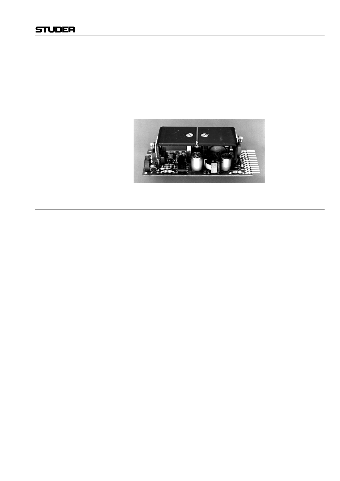
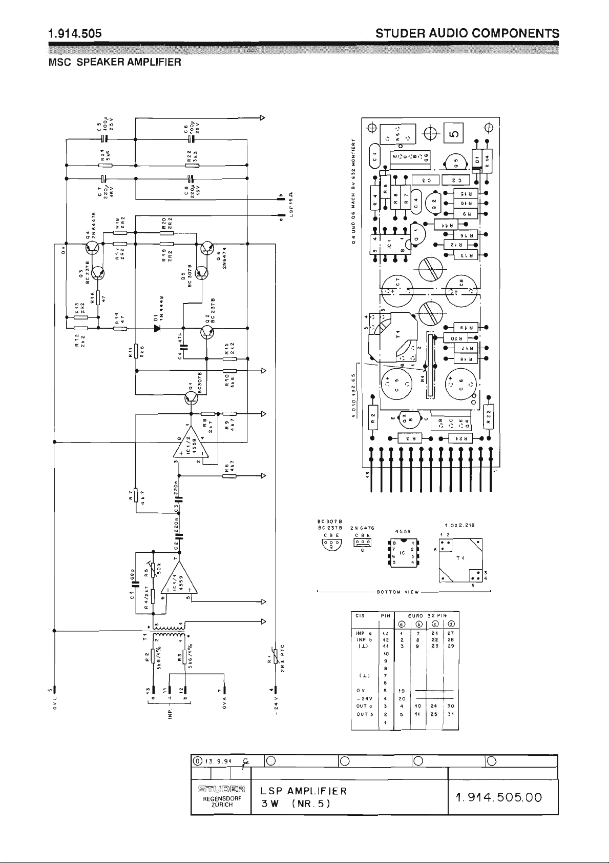
Loudspeaker Amplifier 1.914.505
This low-power amplifier on a modular sub-card is designed to drive a
10...15 Ω speaker. Power output is about 2...3 W. As can be concluded
from this specification, the amplifier is not intended for high-quality monitoring. It will be ideally suited, however, for pre-fader listening and similar
applications. The amplifier’s input is balanced and floating, with adjustable
gain.
Technical Specifications
Input impedance > 10 kΩ, balanced and floating (with transformer)
Nominal power output 2 W into 15 Ω
Power output 25 mW...2.5 W into 15 Ω, with 0 dBu input
Distortion < 0.5% at 2 W
< 0.15% at 500 mW
S/N 99 dB, ref. to 2 W at max. gain
Frequency response –0.5 dB at 15 kHz
High pass filter 150 Hz, 12 dB/oct.
Supply: –24 V (40 mA idling, max. 220 mA fully driven)
Dimensions: MS-card, 34 × 85 mm
Ordering Information: Loudspeaker amplifier 1.914.505.xx
Date printed: 11.12.2006
Page 2
Page 3
Page 4
Professional Audio System Components
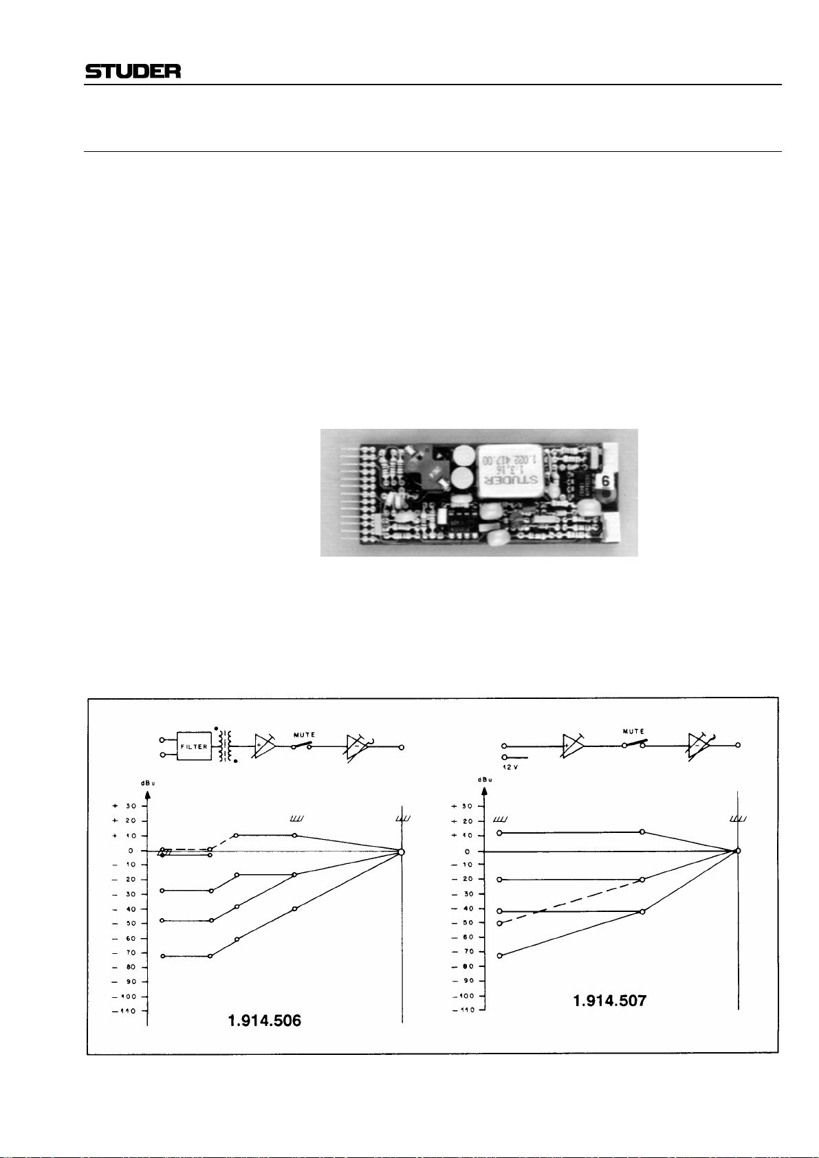
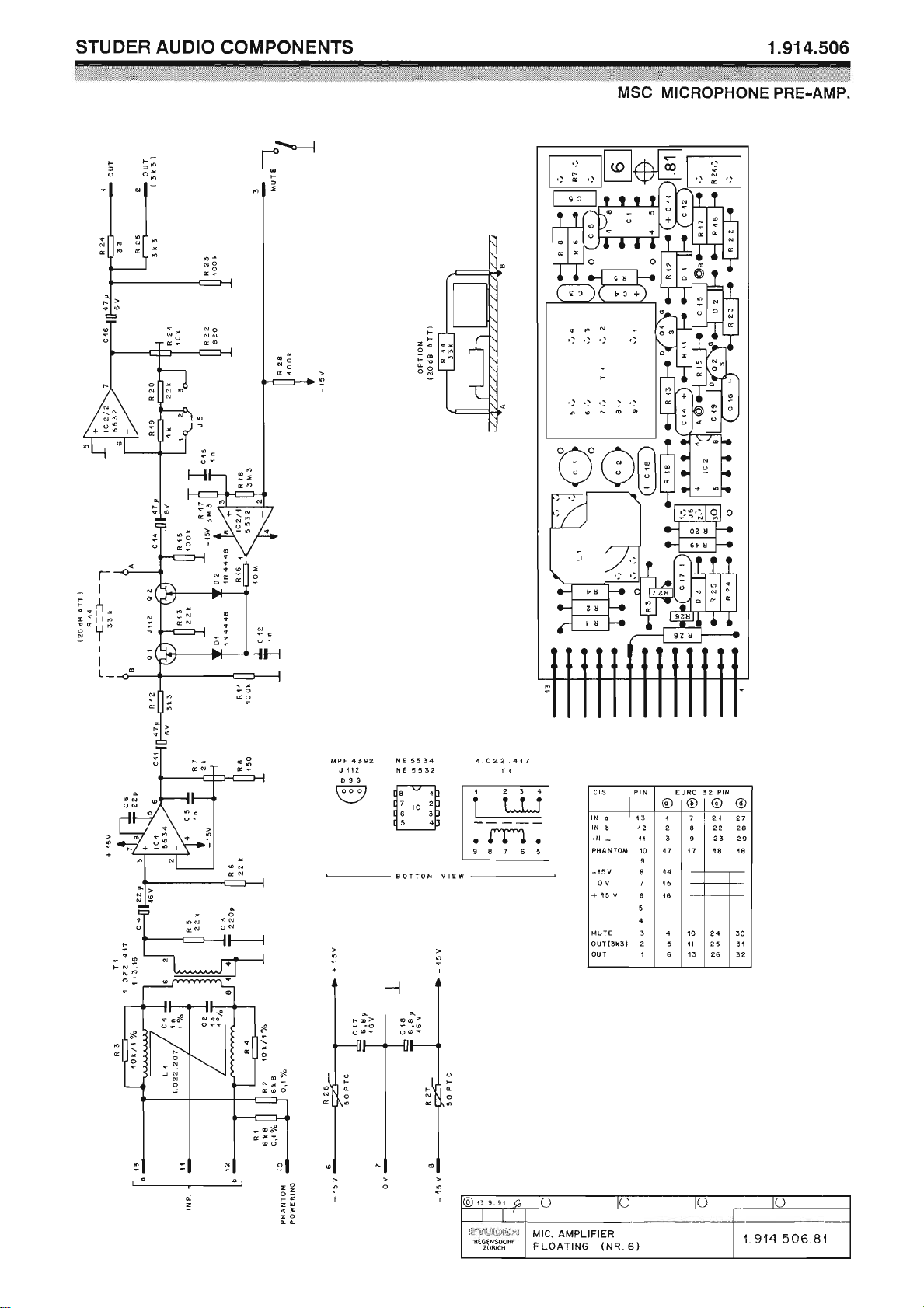
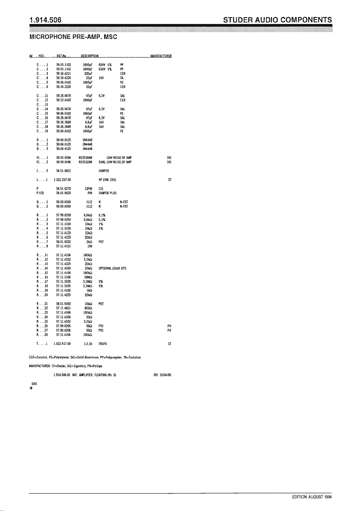
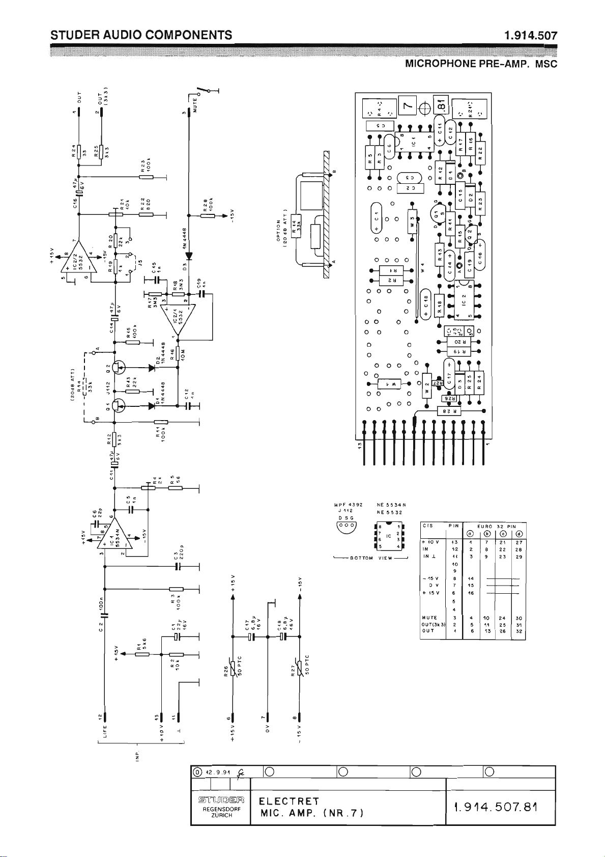
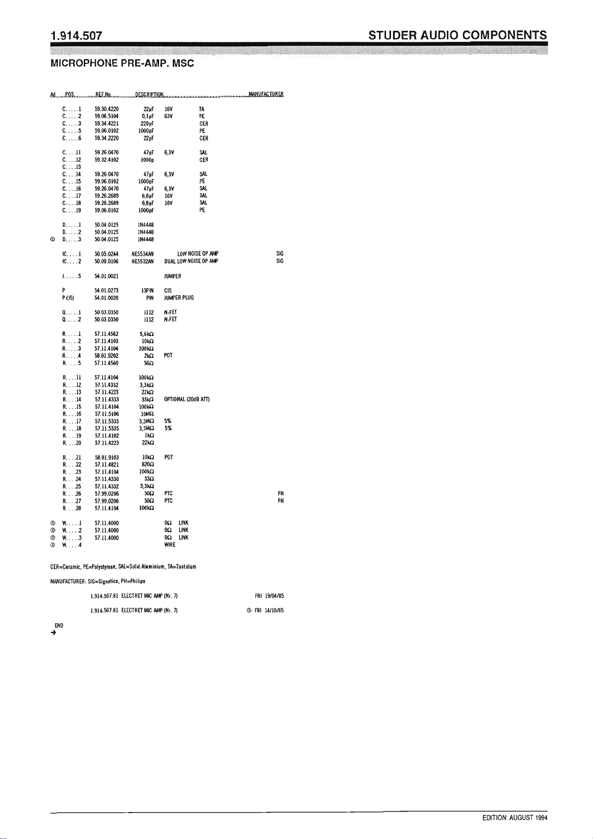
Microphone Pre-Amplifiers 1.914.506/507
Two different microphone pre-amplifiers are available, for dynamic or
condenser microphones, and for electret microphones. Both offer high gain
and low noise, as is required for microphone pre-amplification.
1.914.506 features a balanced and floating input. It is designed for dynamic
or condenser microphones with a source impedance of 200 Ω or less. An
RF filter is incorporated at the input transformer’s primary. Furthermore,
the input is equipped with the resistors required for phantom powering of
condenser microphones.
1.914.507 is designed for unbalanced electret microphones requiring a
12 V supply.
A wide range of input levels can be accommodated (see level diagram).
By using the same solid-state switching circuit as can be found in the line
and high-level amplifiers, remote muting or activation of a fixed amount of
attenuation are possible as well.
The amplifier’s two outputs are unbalanced, with impedances of 3.3 kΩ or
33 Ω, respectively.
Date printed: 11.12.2006
Page 5

Professional Audio System Components
Technical Specifications
Input: Transformer-balanced and floating, with RF filter (1.914.506)
Unbalanced, with RF filter and electret supply (1.914.507)
Impedance > 1 kΩ, for microphones with an impedance of 200 Ω or less.
Max. input level –2 dBu (615 mV
Common mode rejection > 60 dB, unbalanced, to ground
Output: Max. level +20 dBu (7.75 V
Nominal level 0 dBu (0.775 V
Impedance 33 Ω (pin1)
3.3 kΩ (pin2; to a 0-Ω amp.)
Minimum load 600 Ω
Max. gain 71 dB (see level diagram)
Frequency response ±0.5 dB, 30 Hz...16 kHz
THD < 0.3%, 30 Hz...16 kHz at 20 dB gain
Noise figure, linear < 4.5 dB, input terminated with 200 Ω
Supply: ±15 V (11 mA idling)
+48 V (1.914.506, only if phantom powering required)
Dimensions: MS-card, 34 × 85 mm
Ordering Information: • Microphone pre-amplifier for dynamic microphones 1.914.506.xx
• Microphone pre-amplifier for electret microphones 1.914.507.xx
); THD at 30 Hz: approx. 1%
rms
)
rms
)
rms
Date printed: 11.12.2006
Page 6
Page 7
Page 8
Page 9
Page 10
Professional Audio System Components
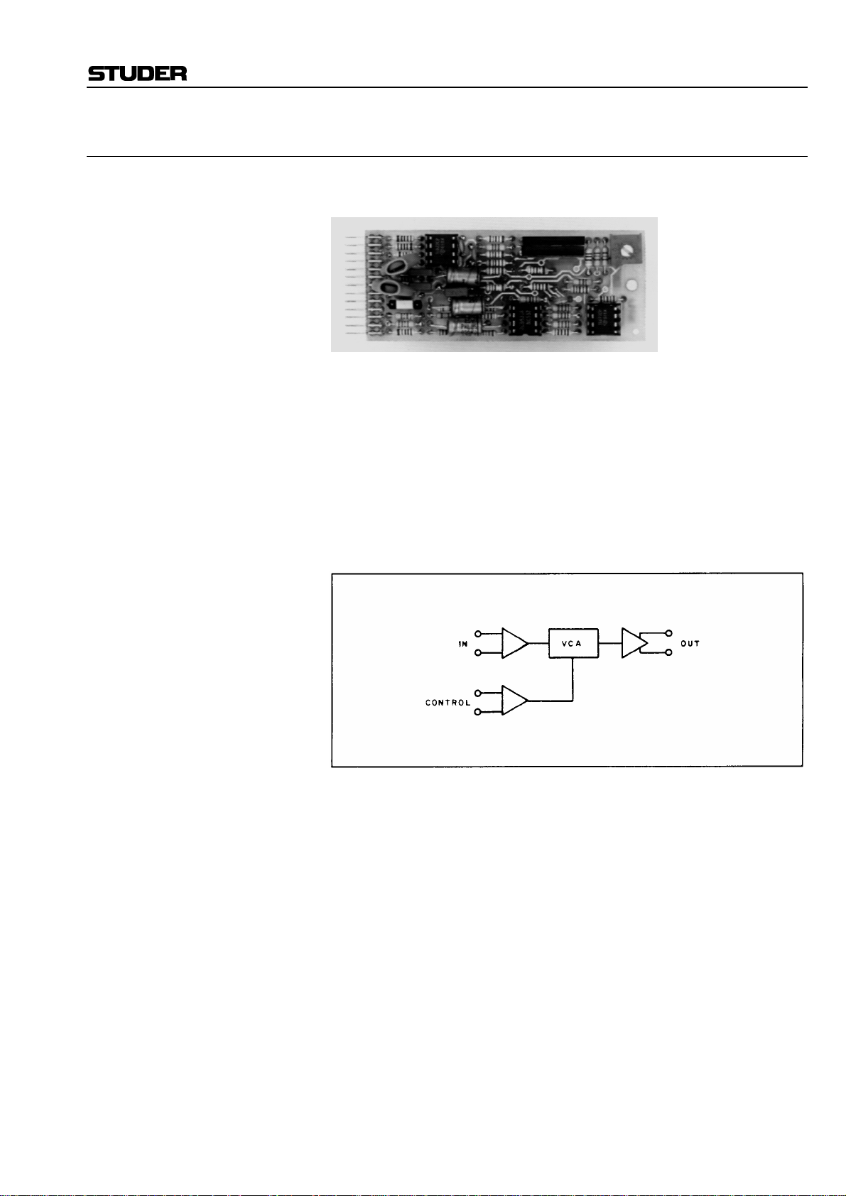
VCA with Electronically Balanced Connections 1.914.515
In contrast to the VCA module 1.914.518/528, this assembly features elec-
tronically balanced input and output.
It is intended for use in balanced audio systems for a variety of applica-
tions, especially when gain is to be controlled from a remote point. It will
be useful in audio-video post-production work where suitable DC ramps
can control cross-fades, voice-overs, etc. Its high overload margin and its
exceptionally low noise and distortion performance make it the perfect
choice for high-quality audio applications.
By connecting the gain control terminals of a number of VCAs to a com-
mon potentiometer or fader, several audio channels may thus be controlled
simultaneously.
Two control inputs provide VCA gain control from two different remote points
Date printed: 12.12.2006
Page 11

Professional Audio System Components
Technical Specifications
Input: Impedance ≥ 10 kΩ, electronically balanced
Clipping point +24 dBu
Output: Electronically balanced
Recommended load ≥ 2 kΩ
Maximum level +24 dBu
Frequency response –0.5 dB, 30 Hz...15 kHz
Gain/attenuation range +40...–100 dB, with ext. control
Control input: pin1; gain tracking 0 V = unity gain;
1 dB/µA; jumper 1-2
20 dB/V; jumper 2-3
10 dB/V; jumper 3-4
Control input: pin10; gain tracking 10 dB/V
THD < 0.1%
Equivalent input noise –93 dBu @ unity gain
Supply: ±15 V (25 mA)
Dimensions: MS-card, 34 × 85 mm
Ordering Information: VCA with electronically balanced input and output 1.914.515.xx
Date printed: 11.12.2006
Page 12

Page 13
Page 14
Professional Audio System Components
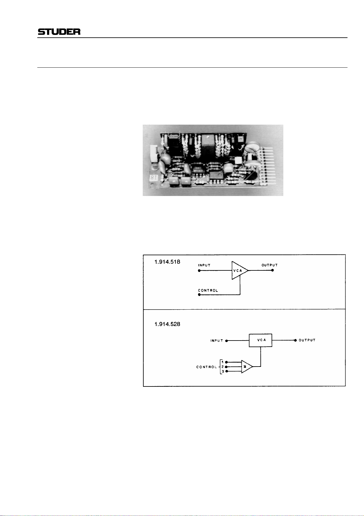
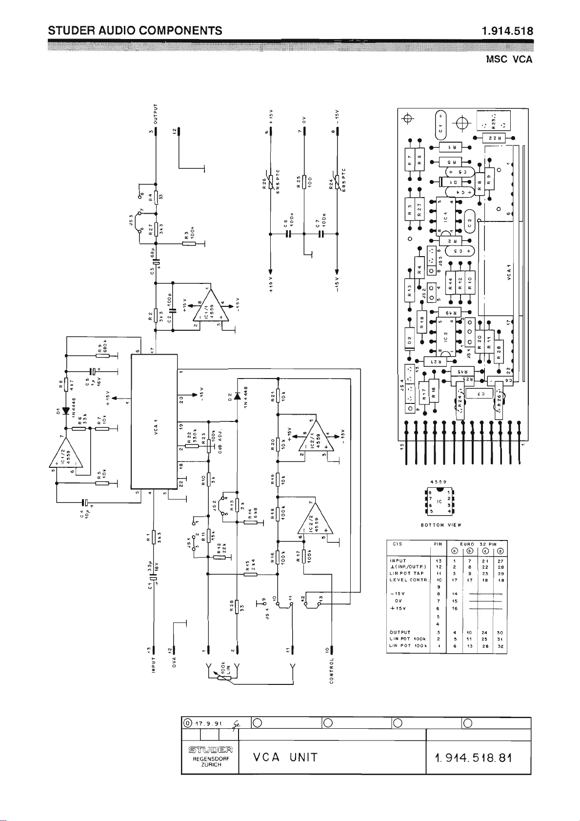
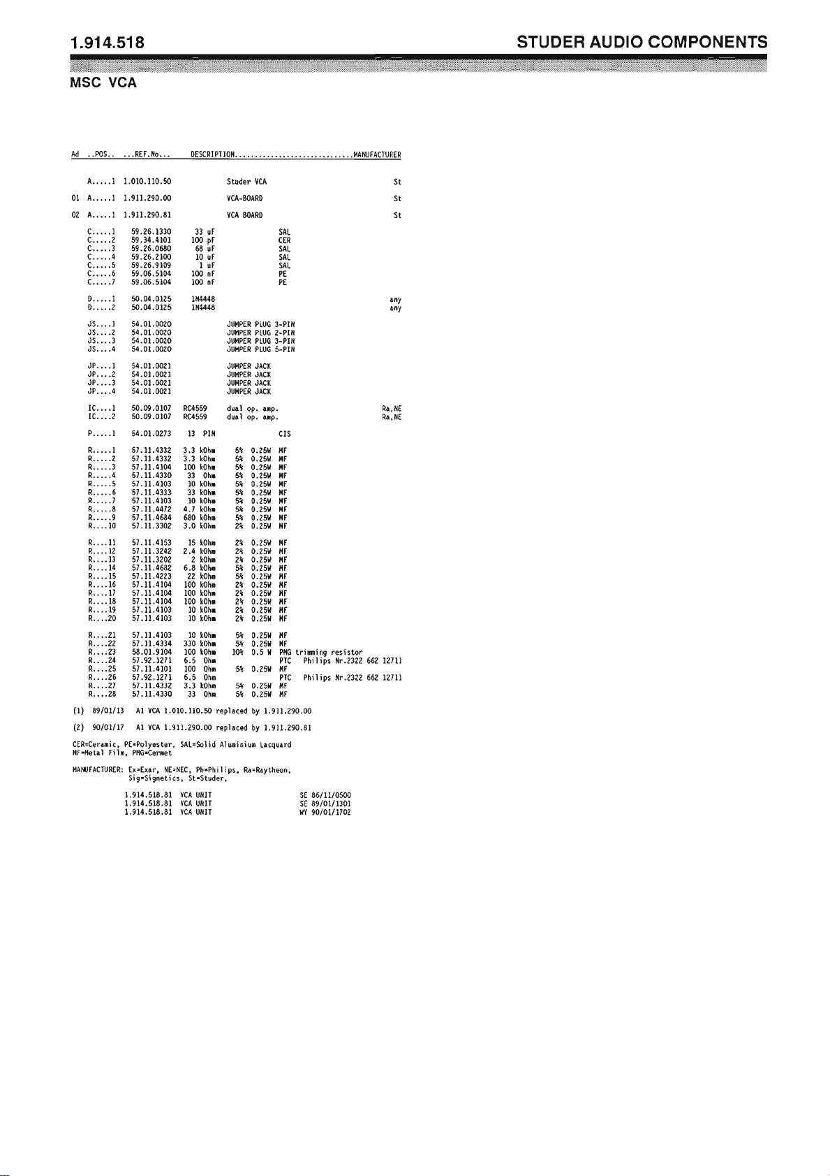
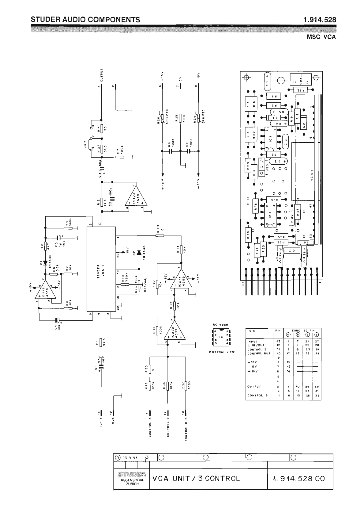
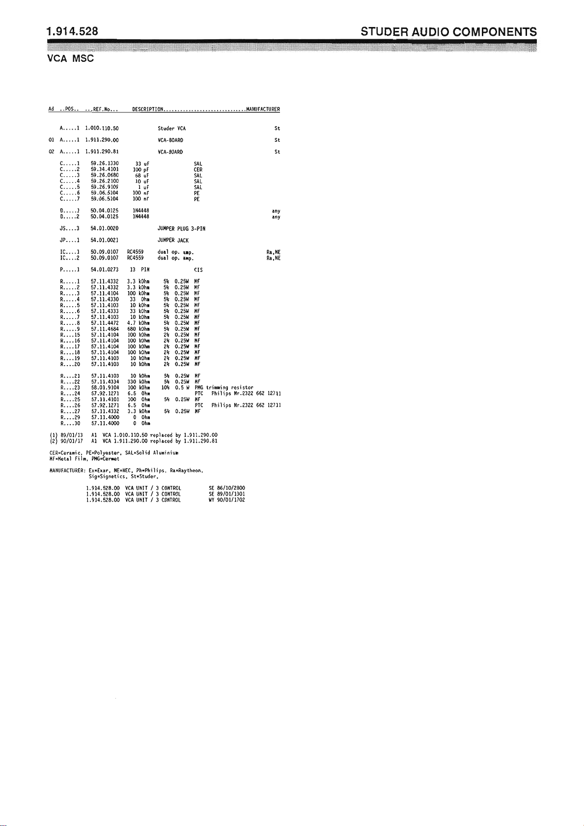
VCA with 1 or 3 Control Ports 1.914.518/528
Within the range of modular sub-cards, two more VCAs are available.
Voltage controlled amplifiers are ideally suited for applications such as
remote level control, level limiting (in combination with the voltage processor 1.914.519) or for automatic “voice-over” circuits, when driven by
suitable ramp generators. These VCAs offer outstandingly low noise and
harmonic distortion.
For best performance, they should be operated at a level of 0 dBu.
Gain pre-selection is possible on the 1.914.518 version, allowing gain/at-
tenuation ranges either from +10 to –90 dB or from +40 to –70 dB, using
an external potentiometer.
The 1.914.528 VCA card differs in that it is equipped with three external
control inputs, providing gain control from three different locations.
Date printed: 11.12.2006
Page 15

Professional Audio System Components
Technical Specifications
Input: Impedance > 3 kΩ
Clipping point +20 dBu
Output: Impedance 33 Ω or 3.3 kΩ, selectable
Max. level +20 dBu
Recommended load ≥ 2 kΩ
Frequency response –0.5 dB, 30 Hz...16 kHz
External gain control +40...–90 dB (1.914.518.xx)
+40...–100 dB (1.914.528.xx)
Gain/attenuation range (pot. meter) +40...–60 dB / +10...–70 dB / +10...–90 dB (1.914.518.xx only, jumper-
selectable)
Gain tracking 10 dB/V
THD < 0.1%
Equivalent input noise –102 dBu
Supply: ±15 V (40 mA)
Dimensions: MS-card, 34 × 85 mm
Ordering Information: Voltage controlled amplifier with 1 control port 1.914.518.xx
Voltage controlled amplifier with 3 control ports 1.914.528.xx
Date printed: 11.12.2006
Page 16
Page 17
Page 18
Page 19
Page 20
Professional Audio System Components
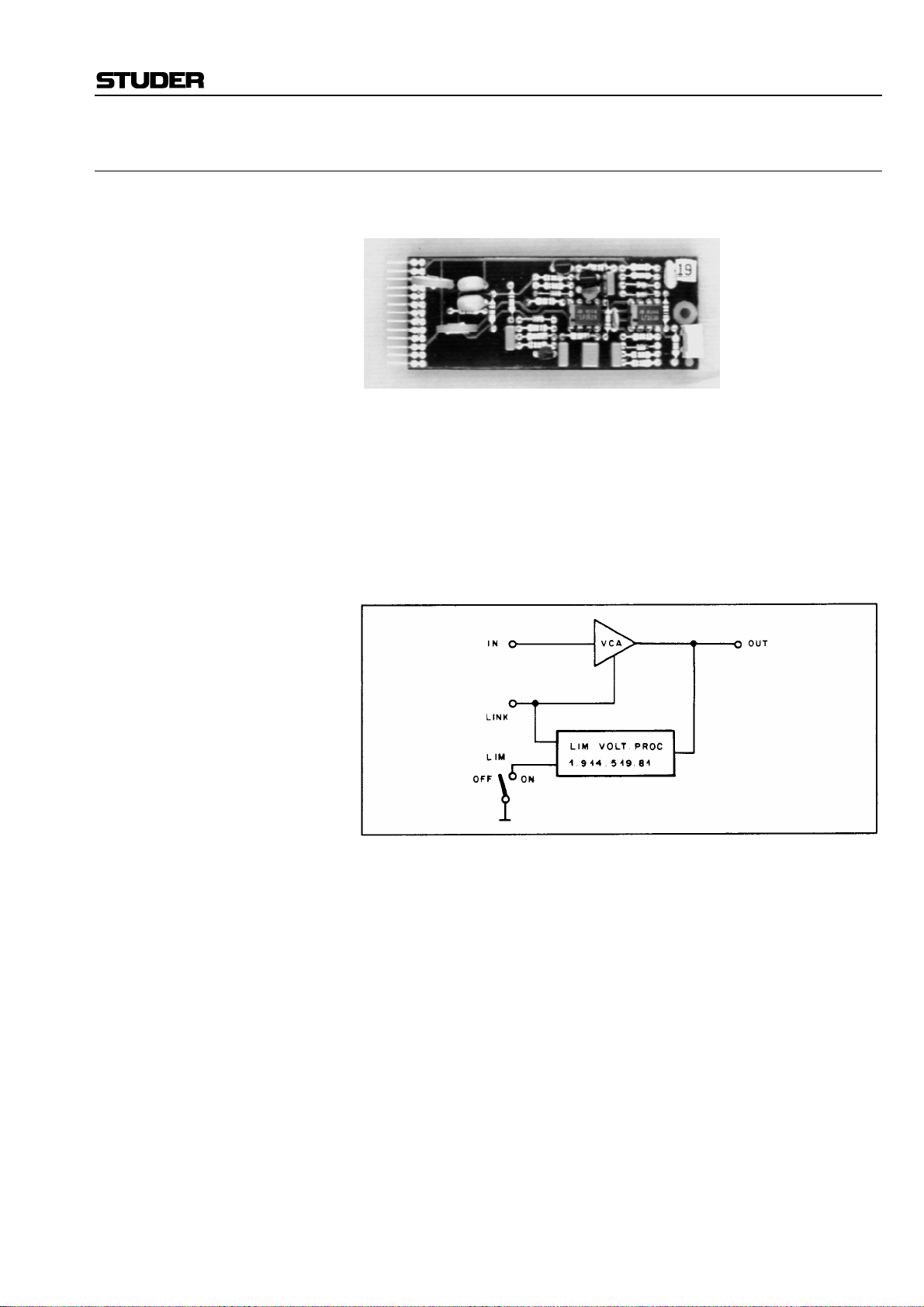
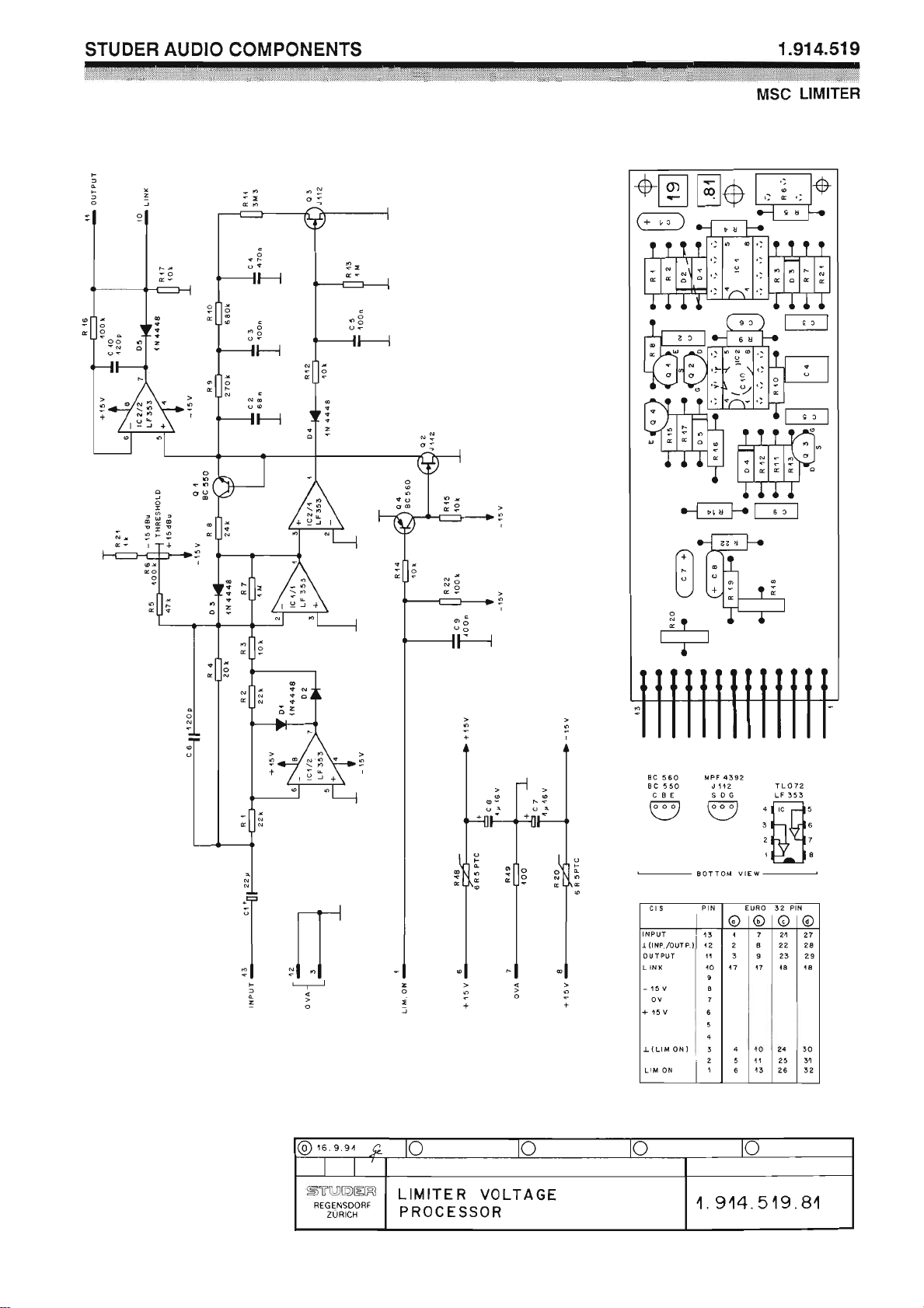
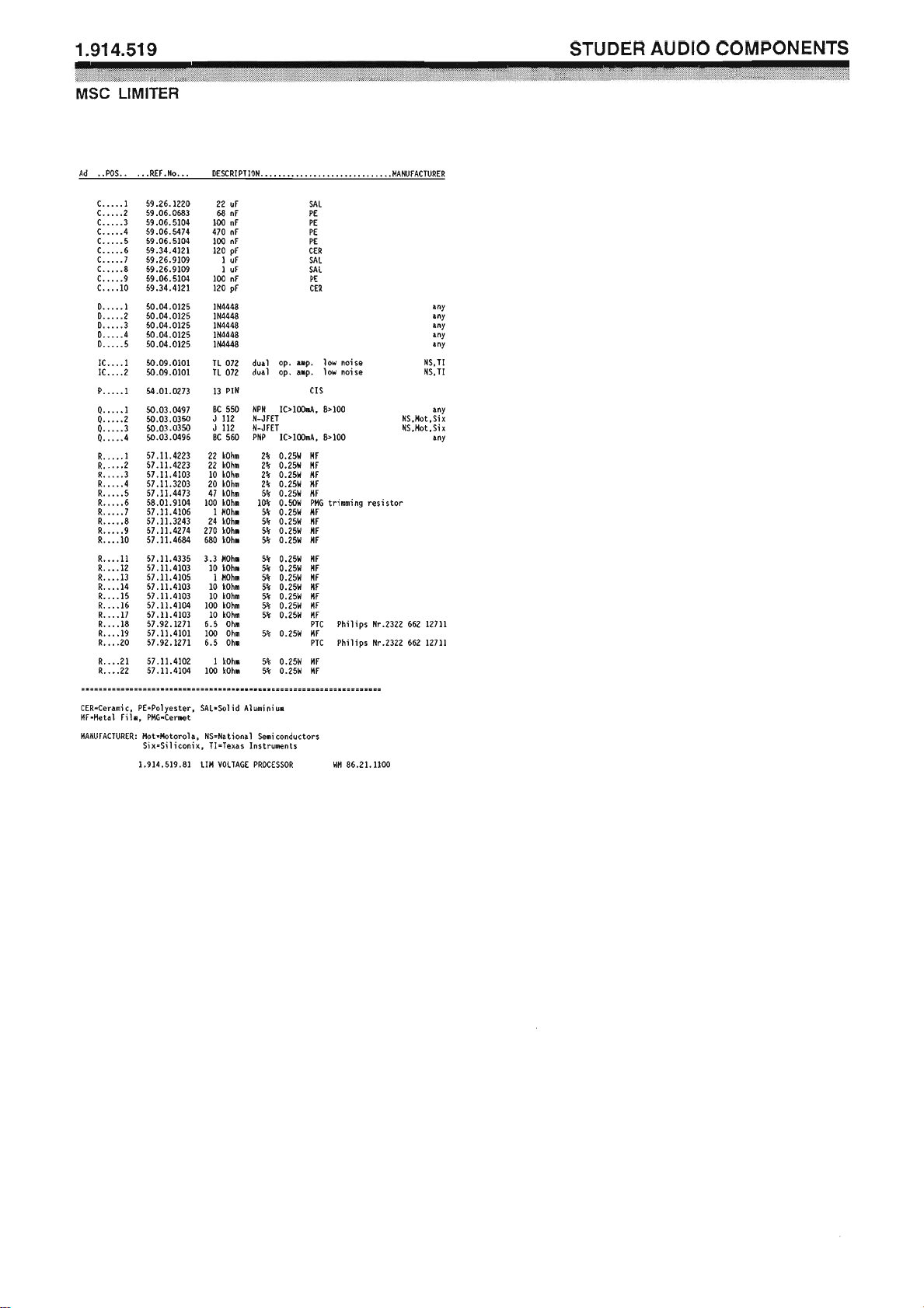
Limiter Voltage Processor 1.914.519
Together with this voltage processor, the VCAs 1.914.518/528 can perform
as signal level limiters.
The processor’s threshold can be set within a wide range of levels, so that
limiting action becomes effective at a desired level within a range of
–15 to +15 dBu. Limiting action attacks within 1 ms, whereas release can
vary from 50 ms to 5 s, depending on the program’s energy content. This
means that no audible “pumping” action – which is often associated with
such a device – will occur. After the cessation of loud passages, amplification will recover only slowly. For stereo applications, a two-channel set-up
(VCAs and voltage processor) can be linked, so that identical amounts of
gain reduction will take place simultaneously in both channels.
The input of the voltage processor has to be wired to the output of the
VCA. The processor’s output, when connected to the VCA’s control terminal, will effect the necessary gain reduction so that a limiting characteristic
is obtained. The limiting threshold is adjustable in a wide range. Remote
on/off switching of the limiter function is possible.
Date printed: 11.12.2006
Page 21

Professional Audio System Components
Technical Specifications
Limiter: Input impedance ≥ 10 kΩ
Max. input level +20 dBu
Frequency range 30 Hz...16 kHz
Output voltage 0...–13 V
Threshold level –15 dBu...+15 dBu
Attack time 1 ms
Release time 50 ms...5 s, program-depending
Compression ratio 20:1, in conjunction with a VCA
Supply: ±15 V (10 mA)
Dimensions: MS-card, 34 × 85 mm
Ordering Information: Limiter voltage processor 1.914.519.xx
DC
Date printed: 11.12.2006
Page 22
Page 23
Page 24
Professional Audio System Components
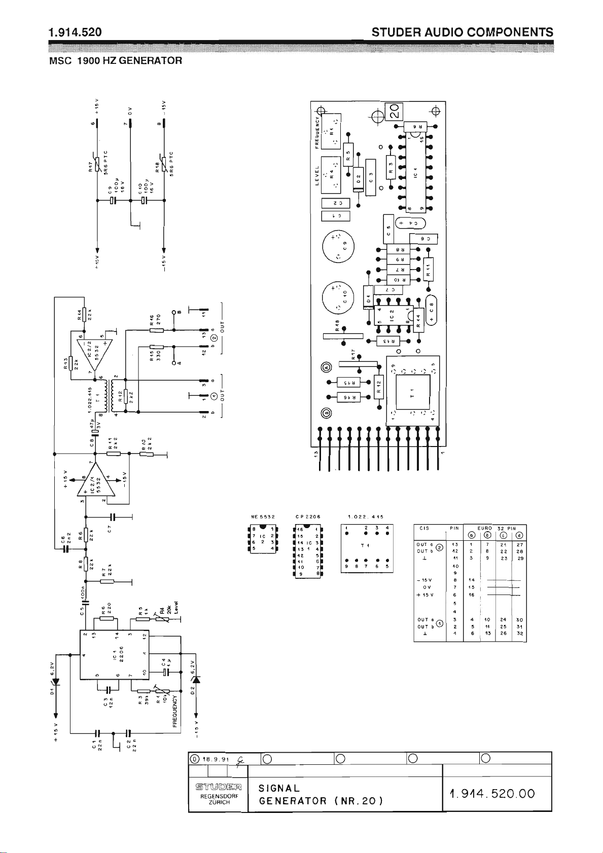
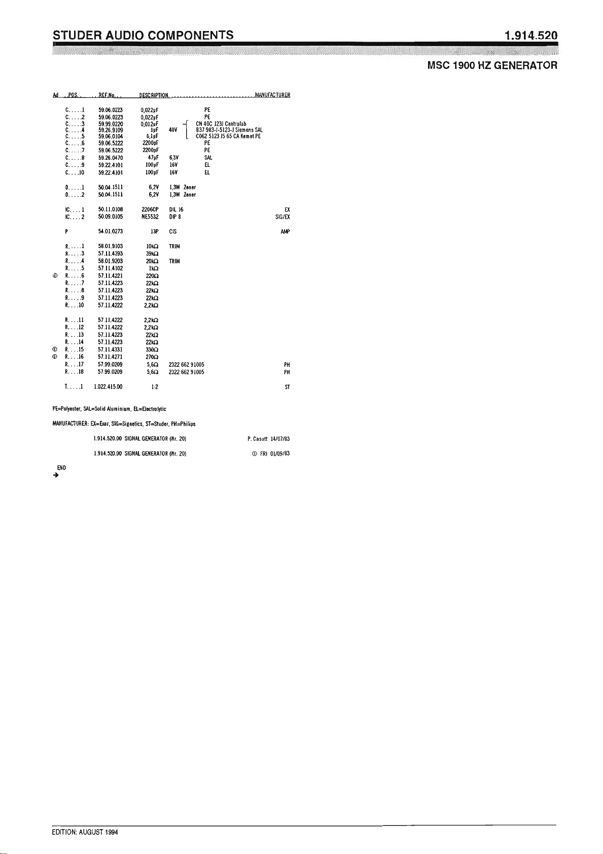
1900 Hz Signal Generator 1.914.520
This signal generator produces a stable frequency of 1900 Hz to establish
communication on outside broadcast lines, as specified in the EBU/CCIR
recommendations.
Technical Specifications
Frequency 1900 Hz (adjustable)
Distortion < 1%
Output level –15...+6 dBu (adjustable)
Output balanced and floating
Output Impedance, out 1 < 15 Ω
out 2 600 Ω
Minimum load 200 Ω
Supply: ±15 V (20 mA)
Dimensions: MS-card, 34 × 85 mm
Ordering Information: 1900 Hz signal generator 1.914.520.xx
Date printed: 11.12.2006
Page 25
Page 26
Page 27
Professional Audio System Components
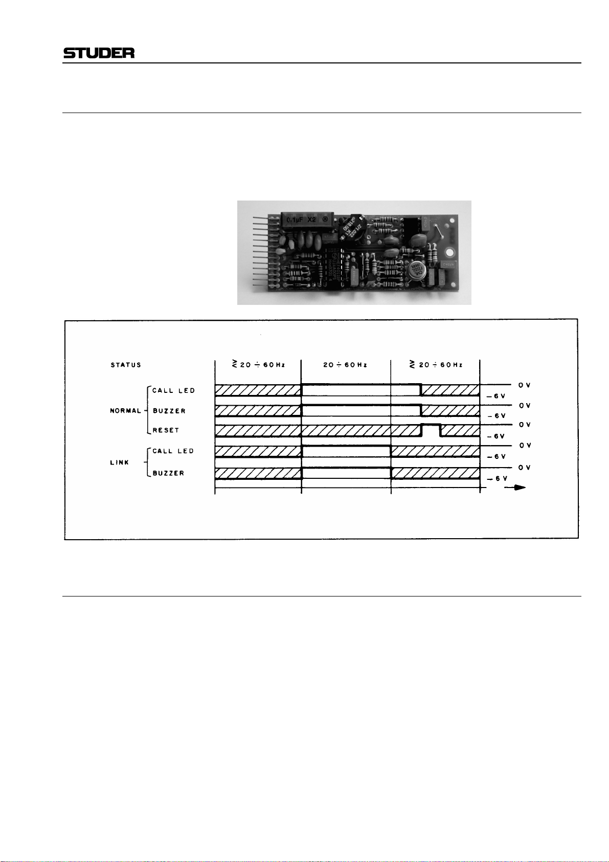
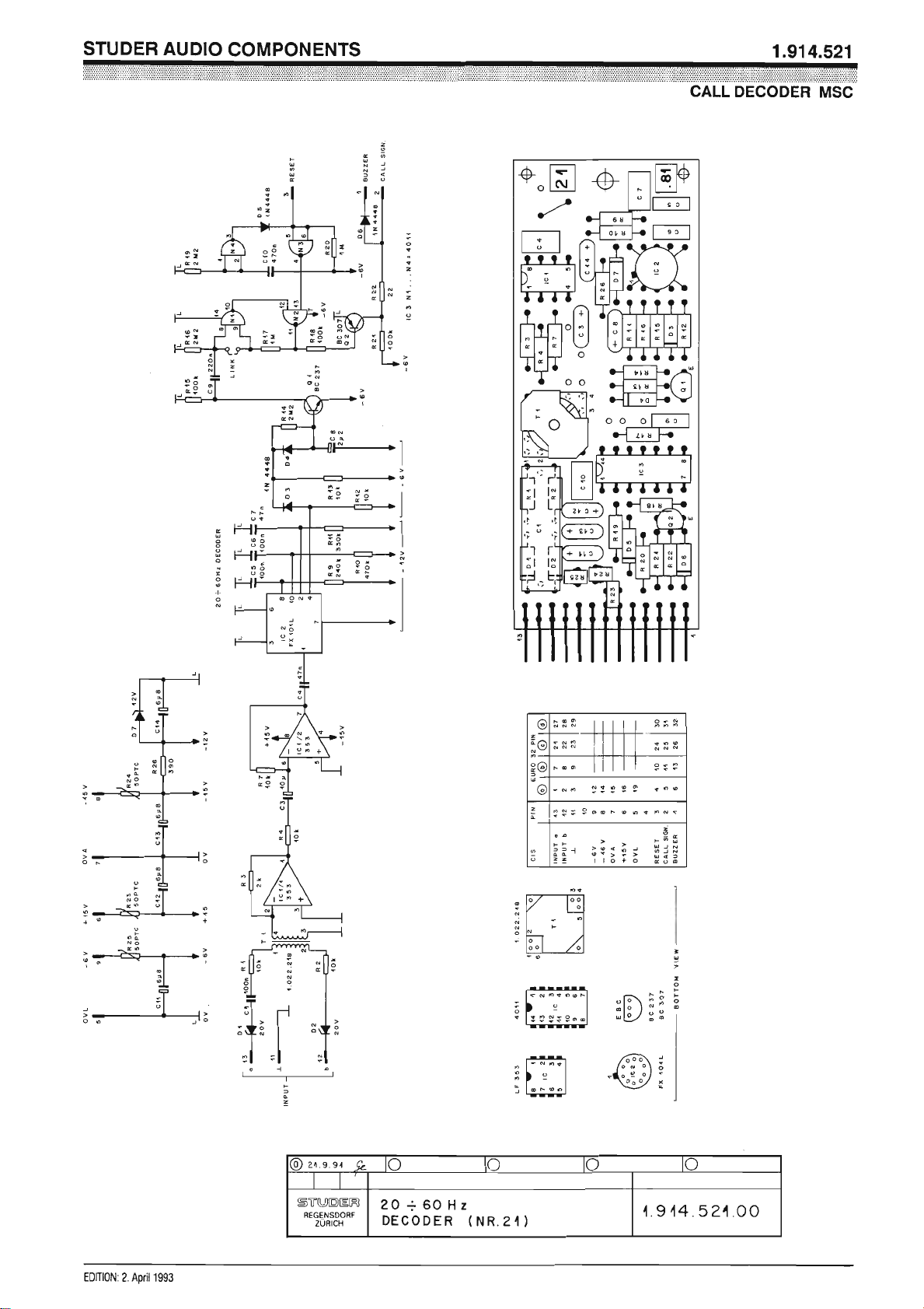
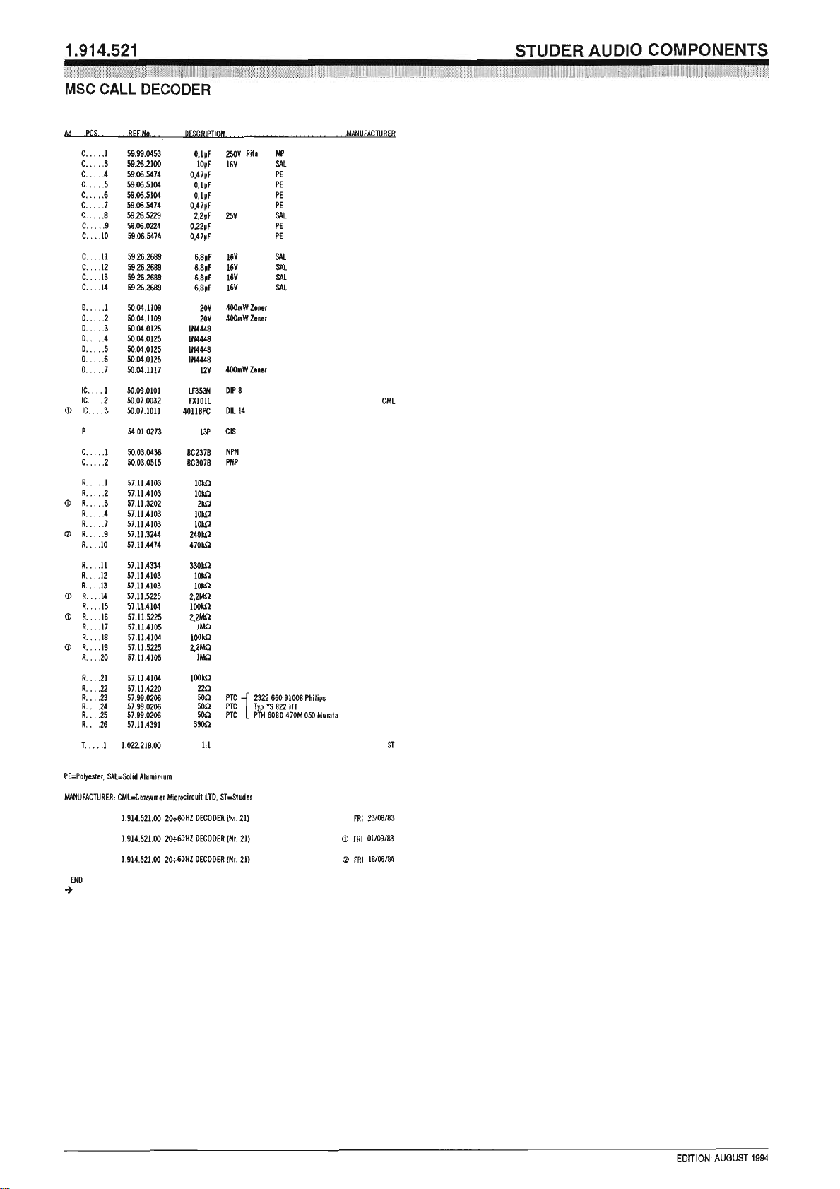
Call Decoder 20...60 Hz 1.914.521
This assembly features a call receiver for the ringing frequency on tele-
phone lines (20...60 Hz). The receiver can activate an optical and/or an
acoustical signal generated by an external buzzer (not supplied). In normal
mode the buzzer will be on until reset. In linked mode the signal lasts only
as long as a call is detected.
Technical Specifications
Input: balanced, floating; no DC
Impedance > 20 kΩ
Frequency 20...60 Hz
Min. level 17 V
Nominal level 70 V
rms
rms
Supply: +15 V (5 mA); –15 V (10 mA); –6 V (2 mA)
Dimensions: MS-card, 34 × 85 mm
Ordering Information: Call decoder 20...60 Hz 1.914.521.xx
Date printed: 11.12.2006
Page 28
Page 29
Page 30
Professional Audio System Components
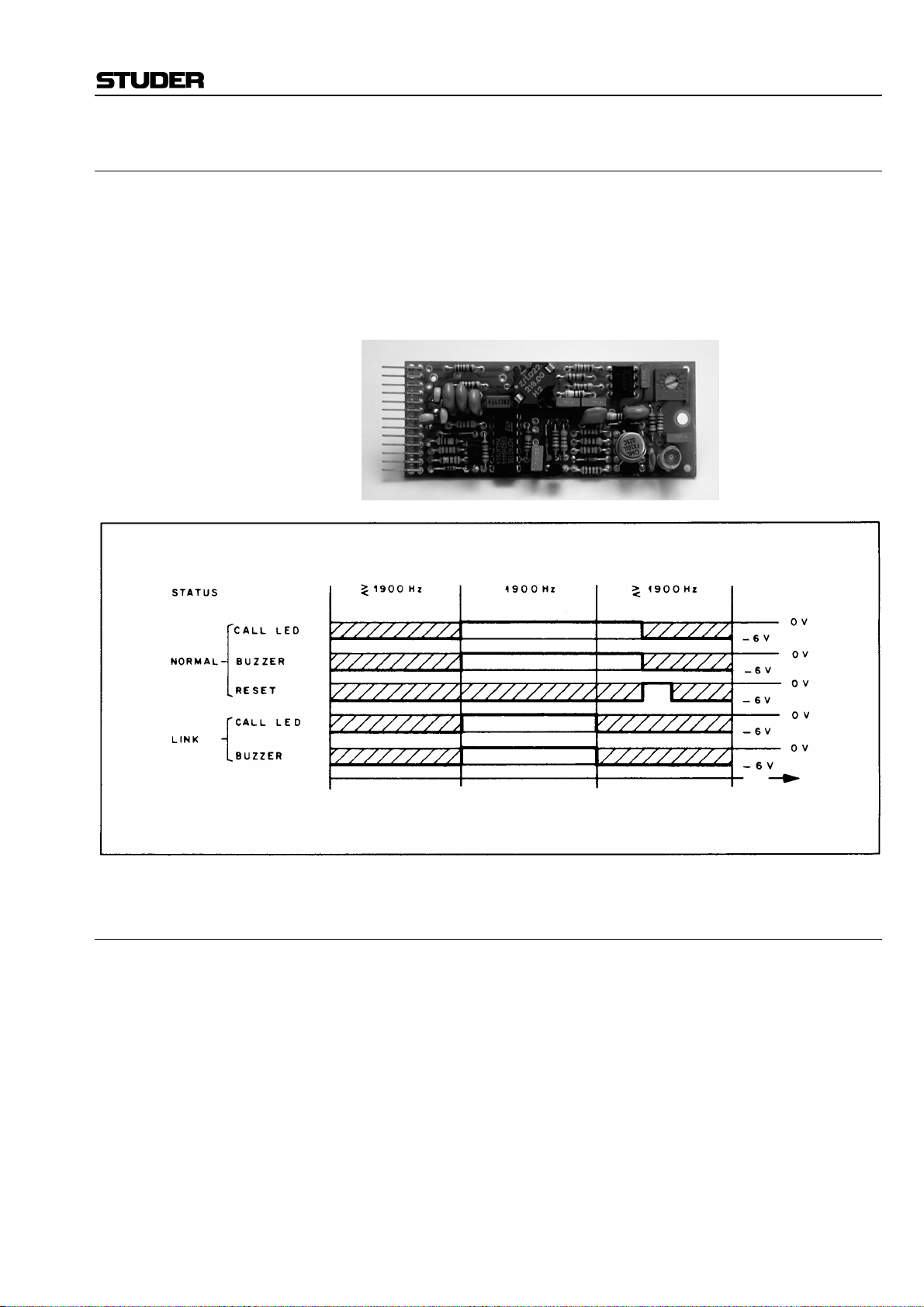
Call Decoder 1900 Hz 1.914.522
This card contains a call receiver for the standardized 1900 Hz call fre-
quency on OB lines. It is tuned to respond to 1900 Hz ±1 %. The receiver
can be switched either to activate an optical or an acoustical signal for the
duration of the 1900 Hz call (linked mode), or the acoustical signal can be
selected to remain activated until reset (normal mode).
The acoustical signal can be generated by an external buzzer (not sup-
plied).
Technical Specifications
Input: balanced, floating; no DC
Frequency 1900 Hz, ±1%
Impedance > 10 kΩ
Min. level –30 dBu
Nominal level +24 dBu
Supply: +15 V (5 mA); –15 V (10 mA); –6 V (2 mA)
Insulation rating 500 V
DC
Dimensions: MS-card, 34 × 85 mm
Ordering Information: Call decoder 1900 Hz 1.914.522.xx
Date printed: 11.12.2006
Page 31

Page 32

Studer Audio Components
Call Decoder 1900 Hz 1.914.522.00 ( 1)
Part No. Qty. Type/Val. DescriptionPos.Idx. Part No. Qty. Type/Val. DescriptionPos.Idx.
C 2 59.06.0102 1n0 PETP, 63V, 10%, RM50
C 3 59.06.0102 1n0 PETP, 63V, 10%, RM50
C 4 59.06.0222 2n2 PETP, 63V, 10%, RM50
C 5 59.05.2472 4n7 PP, 2.5%, 63V0
C 6 59.34.4121 120p CER 63V, 5%, N7500
C 7 59.06.0103 10n PETP, 63V, 10%, RM50
C 8 59.26.5229 2u2 SAL, 20%, 25V0
C 9 59.06.0224 220n PETP, 63V, 10%, RM50
C 10 59.06.5474 470n PETP, 63V, 5%, RM50
C 11 59.26.2689 6u8 SAL 16V 20%0
C 12 59.26.2689 6u8 SAL 16V 20%0
C 13 59.26.2689 6u8 SAL 16V 20%0
C 14 59.26.2689 6u8 SAL 16V 20%0
D 3 50.04.0125 1N4448 75V, 150mA, 4ns, DO-350
D 4 50.04.0125 1N4448 75V, 150mA, 4ns, DO-350
D 5 50.04.0125 1N4448 75V, 150mA, 4ns, DO-350
D 6 50.04.0125 1N4448 75V, 150mA, 4ns, DO-350
D 7 50.04.1117 12V Zener, 5%, 0.5W, DO-350
IC 1 50.09.0101 TL072 Dual op-amp biFET0
IC 2 50.07.0032 FX101 IC FX-101 L, ,A0
IC 3 50.07.1011 4011 Quad 2-inp NAND1
P 1 54.01.0273 13p Stecker CIS parallelsteck0
Q 1 50.03.0515 BC307B PNP 100mA 45V0
Q 2 50.03.0436 BC237B NPN 100mA 45V0
R 1 57.11.3562 5k6 MF, 1%, 02070
R 2 57.11.3562 5k6 MF, 1%, 02070
R 3 57.11.3123 12k MF, 1%, 02070
R 4 57.11.3104 100k MF, 1%, 02070
R 5 57.11.3392 3k9 MF, 1%, 02070
R 7 57.11.5155 1M5 MF, 5%, 02070
R 8 58.01.8203 20k Cermet, 10%, 0.5W, horizontal0
R 9 57.11.3154 150k MF, 1%, 02070
R 10 57.11.3104 100k MF, 1%, 02070
R 11 57.11.3104 100k MF, 1%, 02070
R 12 57.11.3103 10k MF, 1%, 02070
R 13 57.11.3103 10k MF, 1%, 02070
R 14 57.11.5225 2M2 MF, 5%, 02070
R 15 57.11.3104 100k MF, 1%, 02070
R 16 57.11.5225 2M2 MF, 5%, 02071
R 17 57.11.3105 1M0 MF, 1%, 02070
R 18 57.11.3104 100k MF, 1%, 02070
R 19 57.11.5225 2M2 MF, 5%, 02071
R 20 57.11.3105 1M0 MF, 1%, 02070
R 21 57.11.3104 100k MF, 1%, 02070
R 22 57.11.3220 22R MF, 1%, 02070
R 23 57.99.0206 50R PTC, 25V, 0.5W0
R 24 57.99.0206 50R PTC, 25V, 0.5W0
R 25 57.99.0206 50R PTC, 25V, 0.5W0
R 26 57.11.3391 390R MF, 1%, 02070
T 1 1.022.218.00 1 : 1 EINGANGSTRAFO 1 : 10
Page: 1 of 1
(01) IC3, R16, R19 changed
End of List
Date printed: 06.11.2006
Page 33

Professional Audio System Components
Relay Sub-Cards 1.914.523/524/525/526
Audio signal routing or enabling/disabling of certain circuit sections is
often effected best using relays. The Modular Sub-Card System, therefore,
offers a selection of four relays on individual circuit boards. Because only
one relay can be accommodated on one MS-Card, several cards (or a card
from the Euro-card range) will be required if more complex switching has
to be realized.
The relays offer double pole/double throw switching with non-shorting
contacts, and coils rated for either 6 V
or 24 VDC operation. A diode is
DC
wired across the relay coil in all versions to suppress interfering back-EMF
when de-energizing the relay.
For studio applications where the mechanical click produced by the relay’s
armature is objectionable, a low-noise type is available.
No. Coil Contact Rating
/ 137 Ω
1.914.523
1.914.524
* 1.914.525
* 1.914.526
6 V
24 V
5 V
24 V
DC
/ 2.0 kΩ
DC
/ 135 Ω
DC
/ 2.6 kΩ
DC
220 V / 2 A / 60 W
220 V / 2 A / 60 W
100 V / 0.5 A / 30 W
100 V / 0.5 A / 30 W
(R1 = 27 Ω for 6 V operation)
(R1 = 0 Ω)
* Low-noise relays
Dimensions: MS-card, 34 × 85 mm
Ordering Information: MSC relay 6 V
MSC relay 24 V
MSC relay 6 V
MSC relay 24 V
1.914.523.xx
DC
1.914.524.xx
DC
; low-noise 1.914.525.xx
DC
; low-noise 1.914.526.xx
DC
Date printed: 11.12.2006
Page 34

Page 35

Professional Audio System Components
Breadboarding Card 1.914.529
This experimental board is an empty plug-in PCB compatible with the
MSC system. It offers a punched 0.1” grid (2.54 × 2.54 mm) for individual
component placement.
Ordering Information: Breadboarding card 1.914.529.xx
Date printed: 11.12.2006
Page 36

Professional Audio System Components
0-Ω Input Amplifier with PFL Facility 1.914.530
This amplifier with its characteristic input impedance of less than 1 Ω finds
its application as a summing amplifier. A multitude of unbalanced sources
can thus be mixed with a high degree of effective isolation between the individual inputs.
When using 3.3 kΩ resistors as combining (mixing) resistors in series with
each source feeding the summing bus, gain will be unity (0 dB), i.e., the
amplifier’s output level will be equal to the level of the signal source ahead
of the combining resistor. The amplifier’s output is unbalanced, with low
impedance. Additional outputs for monitoring (or pre-listening) can be activated via solid-state switches by remote control.
Technical Specifications
Input: Max. current 2.5 mA
for max. output swing
rms
Current for 0 dBu 234.2 µA; 0 dBu output ( 3.3 kΩ at the input for unity gain)
Output: Impedance 33 Ω
Max. output swing +20 dBu
Load ≥ 600 Ω @ max. output swing
Frequency response ±0.3 dBu, 30 Hz...16 kHz
THD < –75 dB, 30 Hz...16 kHz
Noise voltage at the output –110 dBu, input terminated with 3.3 kΩ, bandwidth 23 kHz
Noise figure, 12 inputs F < 2 dB R
= 275 Ω
S
Supply: +15 V (11 mA idling); –15 V (7 mA idling)
Dimensions: MS-card, 34 × 85 mm
Ordering Information: Zero-Ω input amplifier (PFL facility) 1.914.530.xx
Date printed: 11.12.2006
Page 37

Page 38

Page 39

Professional Audio System Components
High-Level Input with PFL Facility 1.914.531
This compact high-level input amplifier features a balanced and floating
input stage. The output is unbalanced, with low impedance and low distortion up to +24 dBu. An additional PFL monitoring facility is electronically
switchable (FET).
Technical Specifications
Input: Balanced and floating
Impedance > 10 kΩ
Max. level +26 dBu
CMRR > 110 dB @ 50 Hz
> 110 dB @ 16 kHz
Output: Unbalanced
Impedance 33 Ω
Load ≥ 600 Ω @ max. output swing
Max. output swing +20 dBu
Gain –1.4...–17.8 dB
Frequency response ±0.3 dB, 30 Hz...16 kHz
THD < –85 dB, 30 Hz...16 kHz
Noise voltage < –107 dBu, gain –6 dB, bandwidth 23 kHz
Supply: ±15 V (10 mA idling)
Dimensions: MS-card, 34 × 85 mm
Ordering Information: HL input with PFL 1.914.531.xx
Date printed: 11.12.2006
Page 40

Page 41

Page 42

Professional Audio System Components
Flip-flop Unit 1.914.532
The Flip-flop Unit consists of a relay with two DPDT contacts and a flip-
flop circuit with a control input (opto-coupler). A ground pulse from a nonlatching switch applied to the input activates the relay. A next ground pulse
will deactivate it again.
Technical Specifications
Input: floating, with opto-coupler
Relay contacts: Max. rating 100 V/0.5 A/30 W
Supply: –6 V for logic
–24 V for opto-coupler
Dimensions: MS-card, 34 × 85 mm
Ordering Information: Flip-flop unit 1.914.532.xx
Date printed: 11.12.2006
Page 43

Page 44

Professional Audio System Components
90° Filter 1.914.533
This active 90° filter is used to form a monophonic signal from the left and
right channel of stereo signals. Simple mixing of the left and right channel
will not produce a mono signal of satisfactory quality, but results in an emphasis of the center information. By summing the stereo signals in a 90°
phase-shifted manner, this undesirable effect can be avoided.
The 90° filter consists of two all-pass filter chains, producing a uniform
90° phase difference across the whole audio range. The left and the right
stereo signals are each passed through one of these filters and added at the
filter’s output. Doubling of equally-phased signal components as well as
canceling of opposite-phased components is thus avoided.
The filter circuits are of unbalanced configuration. For this reason a sum-
ming circuit usually consists of two high-level amplifiers with balanced inputs (1.914.502), one 90° filter, and one high-level output amplifier
(1.914.501), all accommodated on one MSC motherboard, as shown in the
diagram above.
The gain of this combination can be adjusted. A correlated stereo input of
equal level in both channels will provide a mono signal of identical level.
With only one input channel (left or right), the mono output level will be
lower by 3 dB.
Since the 90° filter with its input and output cards can be realized on a
single, Euro-card size MSC motherboard, it can possibly be combined with
other Audio Components, such as limiters and isolation amplifiers. Such
stereo-to-mono combinations are in use at various radio stations to feed the
stereo programs to the monophonic AM-transmitter in a correctly summed
manner.
Date printed: 11.12.2006
Page 45

Professional Audio System Components
Technical Specifications
Input: Max. level +20 dBu
Impedance 4 kΩ
Output: Max. level +20 dBu
Impedance 6.8 kΩ
Frequency response 30 Hz...16 kHz, ±0.3 dB
Phase 90° ±3°; 30 Hz...16 kHz
THD ≤ –80 dB
Noise < –95 dBu
Supply: ±15 V (18 mA idling)
Dimensions: MS-card, 34 × 85 mm
Ordering Information: 90° filter stereo/mono 1.914.533.xx
Date printed: 11.12.2006
Page 46

Page 47

Page 48

Professional Audio System Components
Dual Vox Detector 1.914.534
The Dual Vox Detector card contains two adjustable threshold level detec-
tor circuits. Threshold level (–22 dBu...+16 dBu) and release time
(0.2 s...10 s) are separately adjustable for two audio channels. These adjustments are effected very precisely with multi-turn trimmer potentiometers.
The high-impedance audio input is balanced. The open-collector output is
prepared to activate a relay or an alarm device.
A possible application of this card would be to detect incoming modula-
tion.
Technical Specifications
Inputs: Electronically balanced
Impedance ≥ 10 kΩ
Max. level +24 dBu (0 dBu 0,775 V
rms
)
Frequency response 75 Hz...12 kHz, –3 dB
Threshold level –22 dBu...+16 dBu
Attack time 100 ms
Release time 200 ms...10 s
Hysteresis ≤ 1 dB
Outputs: Open-collector; U
≤ +45 V; Imax ≤ 100 mA
CE
Supply: ±15 V (≤ 15 mA / 4 mA idling)
Dimensions: MS-card, 34 × 85 mm
Ordering Information: Dual vox detector 1.914.534.xx
Date printed: 11.12.2006
Page 49

Page 50

Page 51

Professional Audio System Components
Microphone Amplifier with Limiter 1.914.539
This assembly combines a microphone amplifier and a VCA limiter circuit
with adjustable threshold level and program-depending release time. The
input is balanced and floating, the output is unbalanced and with low impedance. Gain control is effected internally with a trimmer potentiometer,
or externally with a gain-control DC voltage. A jumper-selectable pad reduces the input level by 21 dB.
The operation of the limiter circuit can be monitored at the gain reduction
output, if an appropriate instrument (GRM) is connected.
This card is ideally suited for talkback applications.
Date printed: 11.12.2006
Page 52

Professional Audio System Components
Technical Specifications
Input: Impedance > 1 kΩ, balanced, floating
Max. level –2 dBu (THD at 30 Hz ≤ 1%)
+19 dBu, pad on
Pad (attenuation) –21 dB, jumper-selectable
CMRR > 60 dB @ 16 kHz
Source impedance ≤ 200 Ω
Output: Max. level +20 dBu
Impedance 33 Ω
Load ≥ 2 kΩ
Gain adjust (v
max. +37 dB, VCA = 0 dB; pad off
min. –11 dB, VCA = 0 dB; pad on
max. +16 dB, VCA = 0 dB; pad on
Gain control characteristics (v
DC range –10...+6 V, pin3: gain control input
Total gain v
Max. attenuation > 90 dB
General: Frequency response ±0.5 dB, 30 Hz...16 kHz
THD ≤ –50 dB, 20 dB gain; 30 Hz...16 kHz
Noise voltage –95 dBu, pad on; 0 dB gain
Noise figure F ~ 10 dB, bandwidth = 23 kHz; 60 dB gain; R
Limiter: Threshold level –7...+20 dBu
Attack time 0.5 ms
Release time 50 ms...1 s, program-dependent
Compression ratio 10:1 @ 1 kHz
Supply: ±15 V (25 mA)
Ordering Information: Microphone amplifier with limiter 1.914.539.xx
) min. +10 dB, VCA = 0 dB; pad off
1
) 10 dB/V
2
= v1 + v2
tot
= 200 Ω; pad off
s
Date printed: 11.12.2006
Page 53

Page 54

Page 55

Professional Audio System Components
Dual Fader/VCA Control Voltage Interface 1.914.540 /541
These interfaces are used to convert the voltage of a linear fader to the non-
linear dB scale of a Studer VCA. One card processes two channels. It is
available in two versions: 540.xx (0...+10 V
(+5...0 V
control voltage). A regulated +10 VDC reference voltage is gen-
DC
erated on-board. The DC from the fader's wiper is connected to the input.
Offset and scale alignment is performed with on-board trimmer potentiometers for matching the VCA gain to the dB scale of the fader.
control voltage), and 541.xx
DC
Technical Specifications
1.914.540.xx 1.914.541.xx
Input: Impedance > 1 MΩ, unbalanced 100 kΩ, unbalanced
Level range
0...+10 V +5...0 V
Output: Impedance 33 Ω, unbalanced 33 Ω, unbalanced
Control range
+1 V...–10 V +1 V...–10 V
Supply: ±15 V (15 mA)
Dimensions: MS-card, 34 × 85 mm
Ordering Information: Fader/VCA control interface 1.914.540.xx
Fader/VCA control interface 1.914.541.xx
Date printed: 11.12.2006
Page 56

Page 57

Page 58

Page 59

Page 60

Studer Audio Components
Dual Fader/VCA Control Voltage IF 1.914.541.00 ( 0)
Part No. Qty. Type/Val. DescriptionPos.Idx. Part No. Qty. Type/Val. DescriptionPos.Idx.
C 1 59.60.3325 10n CER 50V, 10%, X7R, 080501 pce
C 2 59.60.2249 100p CER 50V, 5%, C0G, 060301 pce
C 3 59.60.2373 1n0 CER 50V, 5%, C0G, 080501 pce
C 4 59.60.3337 100n CER 50V, 10%, X7R, 080501 pce
C 5 59.60.3337 100n CER 50V, 10%, X7R, 080501 pce
C 6 59.60.2249 100p CER 50V, 5%, C0G, 060301 pce
C 7 59.68.0065 10u EL 16V, 4.0*5.701 pce
C 8 59.60.2373 1n0 CER 50V, 5%, C0G, 080501 pce
C 9 59.60.3325 10n CER 50V, 10%, X7R, 080501 pce
IC 1 50.61.0201 TL062 Dual FET Op-Amp01 pce
IC 2 50.10.0106 TL431 Shunt regulator01 pce
IC 3 50.61.0201 TL062 Dual FET Op-Amp01 pce
IC 4 50.61.0201 TL062 Dual FET Op-Amp01 pce
MP 1 1.914.541.11 FADER/VCA INTERFACE2 PCB01 pce
MP 2 1.914.541.04 NR.-ETIKETTE 5 * 2001 pce
MP 3 43.01.0108 Label ESE-Warnschild01 pce
P 1 54.01.0273 13p Stecker CIS parallelsteck01 pce
Q 1 50.60.0002 BC850C NPN 45V 100mA SOT 2301 pce
Q 2 50.60.0002 BC850C NPN 45V 100mA SOT 2301 pce
Q 3 50.60.1002 BC860C PNP 45V 100mA SOT 2301 pce
Q 4 50.60.1002 BC860C PNP 45V 100mA SOT 2301 pce
Q 5 50.60.1002 BC860C PNP 45V 100mA SOT 2301 pce
Q 6 50.60.1002 BC860C PNP 45V 100mA SOT 2301 pce
Q 7 50.60.0002 BC850C NPN 45V 100mA SOT 2301 pce
Q 8 50.60.0002 BC850C NPN 45V 100mA SOT 2301 pce
Q 9 50.60.1002 BC860C PNP 45V 100mA SOT 2301 pce
Q 10 50.60.1002 BC860C PNP 45V 100mA SOT 2301 pce
R 1 57.60.1101 100R MF, 1%, 0204, E2401 pce
R 2 57.60.1223 22k MF, 1%, 0204, E2401 pce
R 3 57.60.1113 11k MF, 1%, 0204, E2401 pce
R 4 not used 22k MF, 1%, 0204, E2401 pce
R 5 57.60.1104 100k MF, 1%, 0204, E2401 pce
R 6 57.60.1204 200k MF, 1%, 0204, E2401 pce
R 7 57.60.1113 11k MF, 1%, 0204, E2401 pce
R 8 57.60.1333 33k MF, 1%, 0204, E2401 pce
R 9 57.60.1223 22k MF, 1%, 0204, E2401 pce
R 10 57.60.1223 22k MF, 1%, 0204, E2401 pce
R 11 57.60.1223 22k MF, 1%, 0204, E2401 pce
R 12 57.60.1393 39k MF, 1%, 0204, E2401 pce
R 13 57.60.1241 240R MF, 1%, 0204, E2401 pce
R 14 57.60.1393 39k MF, 1%, 0204, E2401 pce
R 15 57.60.1223 22k MF, 1%, 0204, E2401 pce
R 16 57.60.1330 33R MF, 1%, 0204, E2401 pce
R 17 57.92.1820 94mA PTC 60V01 pce
R 18 57.92.1820 94mA PTC 60V01 pce
R 19 57.60.1681 680R MF, 1%, 0204, E2401 pce
R 20 57.60.1223 22k MF, 1%, 0204, E2401 pce
R 21 57.60.1223 22k MF, 1%, 0204, E2401 pce
R 22 57.60.1223 22k MF, 1%, 0204, E2401 pce
01 pce
R 23 57.60.1223 22k MF, 1%, 0204, E24
R 24 57.60.1393 39k MF, 1%, 0204, E2401 pce
R 25 57.60.1223 22k MF, 1%, 0204, E2401 pce
R 26 57.60.1223 22k MF, 1%, 0204, E2401 pce
R 27 57.60.1113 11k MF, 1%, 0204, E2401 pce
R 28 not used 22k MF, 1%, 0204, E2401 pce
R 29 57.60.1104 100k MF, 1%, 0204, E2401 pce
R 30 57.60.1204 200k MF, 1%, 0204, E2401 pce
R 31 57.60.1241 240R MF, 1%, 0204, E2401 pce
R 32 57.60.1393 39k MF, 1%, 0204, E2401 pce
R 33 57.60.1223 22k MF, 1%, 0204, E2401 pce
R 34 57.60.1330 33R MF, 1%, 0204, E2401 pce
R 35 57.60.1684 680k MF, 1%, 0204, E2401 pce
R 36 57.60.1684 680k MF, 1%, 0204, E2401 pce
RA 1 58.01.9103 10k Cermet, 10%, 0.5W, vertical01 pce
RA 2 58.01.9101 100R Cermet, 10%, 0.5W, vertical01 pce
RA 3 58.01.9103 10k Cermet, 10%, 0.5W, vertical01 pce
RA 4 58.01.9101 100R Cermet, 10%, 0.5W, vertical01 pce
Page: 1 of 1
Date printed: 06.11.2006
End of List
Page 61

Page 62

Page 63

Page 64

Page 65

Page 66

Page 67

Page 68

Page 69

Page 70

Page 71

Page 72

Page 73

Page 74

Page 75

Page 76

Page 77

Page 78

Professional Audio System Components
Monitor Amplifier and Switching Relays (Studio/CR) 1.915.304
The circuit on this Euro-card is designed to form part of an audio monitor-
ing system. The card is narrower than most others, i.e., 4 M units only. It
contains four amplifiers, each presenting a 0-Ω input impedance, two metering amplifiers, and four relays for audio switching.
Two stereo signal inputs from a combination of sources (with suitable iso-
lation resistors at the output of each source) can thus be summed for Control Room (CR) and Studio Monitoring, for example. In addition, the signal
from the stereo master can be assigned to either monitor line and, if
needed, CR monitoring and studio monitoring can be paralleled. A further
circuit permits switchover of level meters from the master bus to the CR
monitor line. The relays are designed for 6 V
operation.
DC
Date printed: 11.12.2006
Page 79

Professional Audio System Components
Technical Specifications
Inputs: balanced and floating (for CR monitor and studio monitor)
Impedance > 10 kΩ
Maximum level +24 dBu
Outputs: unbalanced (for CR monitor and studio monitor)
Impedance < 3 Ω
Maximum level +20 dBu into 1 kΩ
Maximum load 1 kΩ
Meter outputs: push-pull
Maximum level +24 dBu
Frequency response ±0.5 dB, 30 Hz...16 kHz
THD < 0.1%, @ +6 dBu input, 30 Hz...16 kHz
S/N 105 dB, 20 Hz...23 kHz
Supply: ±15 V (20 mA)
Dimensions: Euro-card 100 × 160 mm, 4M units wide (19 mm)
Connector system DIN 41612, type B
Weight approx. 270 g
Ordering Information: Monitor amplifier and switching relay 1.915.304.xx
Date printed: 11.12.2006
Page 80

Page 81

Page 82

Studer Audio Components
Monitor Amp 1.915.304.00 ( 0)
Part No. Qty. Type/Val. DescriptionPos.Idx. Part No. Qty. Type/Val. DescriptionPos.Idx.
C 1 59.32.4471 470p CER , 20%, 50V01 pce
C 2 59.25.4101 100u EL 25V 20% axial01 pce
C 3 59.32.4471 470p CER , 20%, 50V01 pce
C 4 59.25.4101 100u EL 25V 20% axial01 pce
C 5 59.32.4471 470p CER , 20%, 50V01 pce
C 6 59.25.4101 100u EL 25V 20% axial01 pce
C 7 59.25.4101 100u EL 25V 20% axial01 pce
C 8 59.25.4101 100u EL 25V 20% axial01 pce
C 9 59.32.4471 470p CER , 20%, 50V01 pce
C 10 59.25.4101 100u EL 25V 20% axial01 pce
D 1 50.04.0125 1N4448 75V, 150mA, 4ns, DO-3501 pce
D 2 50.04.0125 1N4448 75V, 150mA, 4ns, DO-3501 pce
D 3 50.04.0125 1N4448 75V, 150mA, 4ns, DO-3501 pce
D 4 50.04.0125 1N4448 75V, 150mA, 4ns, DO-3501 pce
IC 1 50.09.0107 4559 Dual Op-Amp01 pce
IC 2 50.09.0107 4559 Dual Op-Amp01 pce
IC 3 50.09.0107 4559 Dual Op-Amp01 pce
K 1 56.04.0146 4*u 6V, 220V/2A, PCB01 pce
K 2 56.04.0146 4*u 6V, 220V/2A, PCB01 pce
K 3 56.04.0146 4*u 6V, 220V/2A, PCB01 pce
K 4 56.04.0146 4*u 6V, 220V/2A, PCB01 pce
R 1 57.11.3682 6k8 MF, 1%, 020701 pce
R 2 57.11.3393 39k MF, 1%, 020701 pce
R 4 57.11.3682 6k8 MF, 1%, 020701 pce
R 5 57.11.3393 39k MF, 1%, 020701 pce
R 7 57.11.3562 5k6 MF, 1%, 020701 pce
R 8 57.11.3562 5k6 MF, 1%, 020701 pce
R 9 57.11.3562 5k6 MF, 1%, 020701 pce
R 10 57.11.3562 5k6 MF, 1%, 020701 pce
R 11 57.11.3334 330k MF, 1%, 020701 pce
R 12 57.11.3562 5k6 MF, 1%, 020701 pce
R 13 57.11.3334 330k MF, 1%, 020701 pce
R 14 57.11.3562 5k6 MF, 1%, 020701 pce
R 15 57.11.3682 6k8 MF, 1%, 020701 pce
R 16 57.11.3393 39k MF, 1%, 020701 pce
R 17 57.11.3562 5k6 MF, 1%, 020701 pce
R 18 57.99.0206 50R PTC, 25V, 0.5W01 pce
R 19 57.99.0206 50R PTC, 25V, 0.5W01 pce
R 20 57.11.3682 6k8 MF, 1%, 020701 pce
R 21 57.11.3393 39k MF, 1%, 020701 pce
R 22 57.11.3562 5k6 MF, 1%, 020701 pce
R 23 57.11.3562 5k6 MF, 1%, 020701 pce
R 24 57.11.3562 5k6 MF, 1%, 020701 pce
R 25 57.11.3562 5k6 MF, 1%, 020701 pce
R 26 57.11.3562 5k6 MF, 1%, 020701 pce
R 27 57.11.3562 5k6 MF, 1%, 020701 pce
R 28 57.11.3562 5k6 MF, 1%, 020701 pce
R 29 57.11.3562 5k6 MF, 1%, 020701 pce
R 30 57.11.3562 5k6 MF, 1%, 020701 pce
T 1 1.022.419.00 EINGANGSTRAFO 1:101 pce
01 pce
T 2 1.022.419.00 EINGANGSTRAFO 1:1
T 3 1.022.419.00 EINGANGSTRAFO 1:101 pce
T 4 1.022.419.00 EINGANGSTRAFO 1:101 pce
Page: 1 of 1
End of List
Date printed: 06.11.2006
Page 83

Professional Audio System Components
Distribution Amplifier 1.915.307/308
The distribution amplifier cards offer splitting of one input to four or six
individually adjustable outputs (versions 1.915.308 or 1.915.307, respectively). The input and all outputs are transformer-balanced and floating.
These cards satisfy any complex requirement of signal routing and distribu-
tion.
Date printed: 11.12.2006
Page 84

Professional Audio System Components
Technical Specifications
General: Frequency range 31.5 Hz...16 kHz
Frequency response +0.2/–0.5 dB, R
Input: balanced and floating
Impedance ≥ 10 kΩ
Symmetry ≥ 60 dB
Gain, adjustable –20...+10 dB (Jumper 2-3: +6 dB Gain)
Outputs: balanced and floating
Impedance ≤ 40 Ω
Maximum level +24 dBu, R
+21 dBu, R
THD ≤ 0.02%, +6 dBu/300 Ω
Output noise voltage –100 dBu, 0 dB gain
Supply: ±15 V
(90 mA, all outputs +6 dBu, without load;
DC
180 mA, all outputs +24 dBu into 300 Ω
Dimensions: Euro-card 100 × 160 mm, 7 M units wide
Weight 500 g (1.915.308)
600 g (1.915.307)
Ordering Information:
Euro-cards: • Distribution amplifier 1 to 6 1.915.307.xx
• Distribution amplifier 1 to 4 1.915.308.xx
19”/1U standard products: • Distribution unit 2 × 1 in/4 out on XLR 75.700.89301
• Distribution unit 3 × 1 in/4 out on XLR 75.700.89302
• Distribution unit 2 × 1 in/6 out on XLR 75.700.89303
= 300 Ω
L
= 600 Ω/THD < 1%
L
= 200 Ω/THD < 1%
L
Date printed: 11.12.2006
Page 85

Page 86

Page 87

Page 88

Page 89

Page 90

Professional Audio System Components
5 W Power Amplifier 1.915.410/415
This amplifier on one Euro-card is designed for operation on a ±15 V sup-
ply. It is capable of providing a power output of 5 W into a load of 8 Ω.
With its low-to-medium power level, this amplifier is ideally suited for
applications such as pre-listening or talkback speaker operation. Its output
stage is protected by instantaneous output power limiting.
The standard version has an electronically balanced (transformerless) input.
It is also available with the following options:
• Input balancing transformer
• Remote muting
• Remote gain control (VCA)
• Input balancing transformer plus remote muting
• Input balancing transformer plus remote gain control (VCA).
Date printed: 11.12.2006
Page 91

Professional Audio System Components
Technical Specifications
Audio: Power output 4 W/15 Ω
5 W/8 Ω
2.5 W/4 Ω, continuous, sine wave
THD < 0.1% @ rated output, 30 Hz...16 kHz
Frequency response ±0.5 dB, 30 Hz...16 kHz
Input impedance 10 kΩ, balanced
Sensitivity –17...+16 dBu (0.11...4.9 V
Maximum input level +24 dBu (12.3 V
) clipping point
rms
S/N 100 dB, linear to 23 kHz at normal operating gain (input +6 dBu)
85 dB, at maximum gain
Supply: ±15 V DC (40 mA idling; 400 mA @ 5 W/8 Ω
Output stage quiescent current 23 mA
Dimensions: Euro-card 100 × 160 mm, 7M units wide
Weight approx. 210 g
Ordering Information:
5 W amplifier with • transformerless input 1.915.410.xx
• input transformer 1.915.411.xx
• transformerless input and remote muting facility 1.915.412.xx
• input transformer and remote muting facility 1.915.413.xx
• transformerless input and remote gain control (VCA) 1.915.414.xx
• input transformer and remote gain control (VCA) 1.915.415.xx
) for rated output
rms
Date printed: 11.12.2006
Page 92

Page 93

Page 94

Page 95

Professional Audio System Components
40 W Power Amplifier 1.915.440/441
For applications where higher power level is needed, a 40 W amplifier has
been realized on a Euro-card. Its width is 32 mm, which equals 7M widths
approximately.
Power is supplied from a separate 45 V
source, as is contained in the 19”
DC
mounting frame 1.918.120.xx. Two amplifier cards will fit into that frame,
making it suitable for applications where stereophonic monitoring is required.
Special Features • Transformerless version with electronically balanced inputs standard
• Version with balanced and floating inputs available
• Output stage protected from overload by momentary power limiting
• Temperature sensing avoids thermal overload
• High-end frequency response limited to prevent transient intermodulation
distortion
• Low distortion performance, even at low power output
• Operation with output transformer possible
Date printed: 11.12.2006
Page 96

Professional Audio System Components
Technical Specifications
Audio: Power output 40 W/4 Ω, continuous, sine-wave,
THD < 0.1 %, 30 Hz...15 kHz (up to rated output)
Output impedance 0.1 Ω
Input impedance 10 kΩ
Common mode rejection > 50 dB, 30 Hz...16 kHz (with input transformer)
Input sensitivity –12...+18 dBu (0.195...6.2 V
in three 10 dB-increments, plus fine-trim range of 12 dB)
Frequency response +0.5/–1 dB, 30 Hz...15 kHz
S/N 105 dB @ maximum gain
90 dB @ minimum gain
Supply: 45 V
(70 mA idling, 1.5 A @ 40 W/4 Ω
DC
Dimensions: Euro-card 100 × 160 mm, 7M units wide
Ordering Information:
Euro-cards • 40 W power amplifier with transformerless input 1.915.440.xx
• 40 W power amplifier with input transformer 1.915.441.xx
19”/1U standard products
40 W power amplifier • Mono version, 19”/1U 75.700.80311
• Stereo version, 19”/1U 75.700.80322
• 19”/1U mounting frame (without amplifier cards) 1.918.120.xx
) for rated output (adjustable with jumper
rms
Date printed: 11.12.2006
Page 97

Page 98

Page 99

Page 100

Professional Audio System Components
Monitor Switching Relays 1.915.601/602
Two different monitor circuit switching cards are available. They are
equipped with either five or eight relays for switching of a corresponding
number of stereo sources to one or two stereo outputs in monitor circuits.
The relay s are available with coil ratings of 6 V
the user’s requirement. Click-suppressing diodes are wired across each relay coil. The relays are equipped with four double throw (change-over)
contacts each.
or 24 VDC, depending on
DC
Isolation of the monitor lines from external circuitry is achieved by 5.6 kΩ
resistors in the “a” and “b” legs of each stereo line, thus a high impedance
(bridging) load is presented to the outside source, even in de-energized
(non-selected) status, when the respective pair of relay contacts shorts the
lines after the respective isolation resistors. With a relay energized, the corresponding stereo pair is routed to a stereo bus available on four pins of the
32-contact edge connector (in case of the 5-input card 1.915.601.xx).
Date printed: 11.12.2006
 Loading...