

Page 1

Medical
For parts or technical
assistance call
800 327 0770 (option 2)
Zoom Critical Care Bed
Model 2040
Maintenance
Page 2

Table of Contents
Introduction
Specifications 4. . . . . . . . . . . . . . . . . . . . . . . . . . . . . . . . . . . . . . . . . . . . . . . . . . . . . . . . . . . . . . . . . . . . . . . . . .
Warning/Caution/Note Definition 4. . . . . . . . . . . . . . . . . . . . . . . . . . . . . . . . . . . . . . . . . . . . . . . . . . . . . . . . . .
Safety Tips and Guidelines 5−7. . . . . . . . . . . . . . . . . . . . . . . . . . . . . . . . . . . . . . . . . . . . . . . . . . . . . . . . . . . . . . . . .
Set−Up Procedures 8. . . . . . . . . . . . . . . . . . . . . . . . . . . . . . . . . . . . . . . . . . . . . . . . . . . . . . . . . . . . . . . . . . . . . . . . .
Symbols 9 − 16. . . . . . . . . . . . . . . . . . . . . . . . . . . . . . . . . . . . . . . . . . . . . . . . . . . . . . . . . . . . . . . . . . . . . . . . . . . . . . .
Preventive Maintenance
Cleaning 17. . . . . . . . . . . . . . . . . . . . . . . . . . . . . . . . . . . . . . . . . . . . . . . . . . . . . . . . . . . . . . . . . . . . . . . . . . . . . .
Preventive Maintenance Checklist 18. . . . . . . . . . . . . . . . . . . . . . . . . . . . . . . . . . . . . . . . . . . . . . . . . . . . . . . .
Nurse Call Battery 19. . . . . . . . . . . . . . . . . . . . . . . . . . . . . . . . . . . . . . . . . . . . . . . . . . . . . . . . . . . . . . . . . . . . .
Circuit Breakers 19. . . . . . . . . . . . . . . . . . . . . . . . . . . . . . . . . . . . . . . . . . . . . . . . . . . . . . . . . . . . . . . . . . . . . . .
Static Discharge Precautions 20. . . . . . . . . . . . . . . . . . . . . . . . . . . . . . . . . . . . . . . . . . . . . . . . . . . . . . . . . . . . . . . . .
Troubleshooting Guide 21 − 26. . . . . . . . . . . . . . . . . . . . . . . . . . . . . . . . . . . . . . . . . . . . . . . . . . . . . . . . . . . . . . . . . .
Electrical System Information
Bed Wiring Diagram 27. . . . . . . . . . . . . . . . . . . . . . . . . . . . . . . . . . . . . . . . . . . . . . . . . . . . . . . . . . . . . . . . . . . .
CPU Board Diagram 28, 29. . . . . . . . . . . . . . . . . . . . . . . . . . . . . . . . . . . . . . . . . . . . . . . . . . . . . . . . . . . . . . . .
Software Configuration 30 − 32. . . . . . . . . . . . . . . . . . . . . . . . . . . . . . . . . . . . . . . . . . . . . . . . . . . . . . . . . . . . .
Power Supply Diagram 33. . . . . . . . . . . . . . . . . . . . . . . . . . . . . . . . . . . . . . . . . . . . . . . . . . . . . . . . . . . . . . . . .
Inverter/Charger Board Diagram 34. . . . . . . . . . . . . . . . . . . . . . . . . . . . . . . . . . . . . . . . . . . . . . . . . . . . . . . . .
Display/CPU Diagram 35. . . . . . . . . . . . . . . . . . . . . . . . . . . . . . . . . . . . . . . . . . . . . . . . . . . . . . . . . . . . . . . . . .
AC Crossover Board Diagram 36. . . . . . . . . . . . . . . . . . . . . . . . . . . . . . . . . . . . . . . . . . . . . . . . . . . . . . . . . . .
Power Board Diagram 37. . . . . . . . . . . . . . . . . . . . . . . . . . . . . . . . . . . . . . . . . . . . . . . . . . . . . . . . . . . . . . . . . .
Inverter Protection Features 38. . . . . . . . . . . . . . . . . . . . . . . . . . . . . . . . . . . . . . . . . . . . . . . . . . . . . . . . . . . . .
Optional Bed Communications Tester 39. . . . . . . . . . . . . . . . . . . . . . . . . . . . . . . . . . . . . . . . . . . . . . . . . . . . .
Head Wall Output Configuration 40. . . . . . . . . . . . . . . . . . . . . . . . . . . . . . . . . . . . . . . . . . . . . . . . . . . . . . . . .
Quick Reference Replacement Parts List 41, 42. . . . . . . . . . . . . . . . . . . . . . . . . . . . . . . . . . . . . . . . . . . . . . . . . . .
Service Information
Brake Pedal Replacement 43. . . . . . . . . . . . . . . . . . . . . . . . . . . . . . . . . . . . . . . . . . . . . . . . . . . . . . . . . . . . . .
Lift Motor and Capacitor Removal and Replacement 44.
Lift Housing Removal and Replacement 45, 46. . . . . . . . . . . . . . . . . . . . . . . . . . . . . . . . . . . . . . . . . . . . . . .
Lift Potentiometer Replacement and Adjustment 47, 48. . . . . . . . . . . . . . . . . . . . . . . . . . . . . . . . . . . . . . . .
Lift Potentiometer “Burn In” Procedure 48. . . . . . . . . . . . . . . . . . . . . . . . . . . . . . . . . . . . . . . . . . . . . . . . . . . .
. . . . . . . . . . . . . . . . . . . . . . . . . . . . . . . . . . . . . . .
Lift Motor Coupler Replacement 49. . . . . . . . . . . . . . . . . . . . . . . . . . . . . . . . . . . . . . . . . . . . . . . . . . . . . . . . .
Power and Sensor Coil Cord Replacement 50, 51. . . . . . . . . . . . . . . . . . . . . . . . . . . . . . . . . . . . . . . . . . . . .
Battery Removal and Replacement 52, 53. . . . . . . . . . . . . . . . . . . . . . . . . . . . . . . . . . . . . . . . . . . . . . . . . . . .
DC Motor Board Removal and Replacement 53. . . . . . . . . . . . . . . . . . . . . . . . . . . . . . . . . . . . . . . . . . . . . . .
Drive Motor Removal and Replacement 54. . . . . . . . . . . . . . . . . . . . . . . . . . . . . . . . . . . . . . . . . . . . . . . . . . .
Drive Wheel Removal and Replacement 54. . . . . . . . . . . . . . . . . . . . . . . . . . . . . . . . . . . . . . . . . . . . . . . . . .
Page 3

Table of Contents
Service Information (Continued)
Scale System Diagnostics and Calibration 55 − 57. . . . . . . . . . . . . . . . . . . . . . . . . . . . . . . . . . . . . . . . . . . . .
Load Cell Replacement 58. . . . . . . . . . . . . . . . . . . . . . . . . . . . . . . . . . . . . . . . . . . . . . . . . . . . . . . . . . . . . . . . .
Head Motor Removal and Replacement 58. . . . . . . . . . . . . . . . . . . . . . . . . . . . . . . . . . . . . . . . . . . . . . . . . . .
Knee Motor Removal and Replacement 59. . . . . . . . . . . . . . . . . . . . . . . . . . . . . . . . . . . . . . . . . . . . . . . . . . .
Power Supply Removal and Replacement 60. . . . . . . . . . . . . . . . . . . . . . . . . . . . . . . . . . . . . . . . . . . . . . . . .
CPU Board Removal and Replacement 60. . . . . . . . . . . . . . . . . . . . . . . . . . . . . . . . . . . . . . . . . . . . . . . . . . .
Fowler Potentiometer Replacement 61. . . . . . . . . . . . . . . . . . . . . . . . . . . . . . . . . . . . . . . . . . . . . . . . . . . . . .
Fowler Potentiometer “Burn−In” Procedure 62. . . . . . . . . . . . . . . . . . . . . . . . . . . . . . . . . . . . . . . . . . . . . . . .
AC Crossover Board Replacement 63. . . . . . . . . . . . . . . . . . . . . . . . . . . . . . . . . . . . . . . . . . . . . . . . . . . . . . .
Display/CPU Board Replacement 63. . . . . . . . . . . . . . . . . . . . . . . . . . . . . . . . . . . . . . . . . . . . . . . . . . . . . . . .
Control Bar Potentiometer Replacement 64, 65. . . . . . . . . . . . . . . . . . . . . . . . . . . . . . . . . . . . . . . . . . . . . . .
Control Bar Potentiometer “Burn−In” Procedure 66. . . . . . . . . . . . . . . . . . . . . . . . . . . . . . . . . . . . . . . . . . . .
Optional Smart TV Interface “Burn−In” Procedure 67. . . . . . . . . . . . . . . . . . . . . . . . . . . . . . . . . . . . . . . . . .
Head and Foot End Siderail Cover Removal 68. . . . . . . . . . . . . . . . . . . . . . . . . . . . . . . . . . . . . . . . . . . . . . .
Head and Foot Molded Siderail Replacement 69. . . . . . . . . . . . . . . . . . . . . . . . . . . . . . . . . . . . . . . . . . . . . .
Head End Siderail Cable Replacement 70, 71. . . . . . . . . . . . . . . . . . . . . . . . . . . . . . . . . . . . . . . . . . . . . . . . .
Foot Board Hinge Removal 72. . . . . . . . . . . . . . . . . . . . . . . . . . . . . . . . . . . . . . . . . . . . . . . . . . . . . . . . . . . . .
Foot Board Module Replacement 73. . . . . . . . . . . . . . . . . . . . . . . . . . . . . . . . . . . . . . . . . . . . . . . . . . . . . . . .
Foot Board Interface Plug Replacement 74. . . . . . . . . . . . . . . . . . . . . . . . . . . . . . . . . . . . . . . . . . . . . . . . . .
Assembly Drawings And Parts Lists
Base Assembly 75 − 82. . . . . . . . . . . . . . . . . . . . . . . . . . . . . . . . . . . . . . . . . . . . . . . . . . . . . . . . . . . . . . . . . . . .
Lift Assembly 83 − 86. . . . . . . . . . . . . . . . . . . . . . . . . . . . . . . . . . . . . . . . . . . . . . . . . . . . . . . . . . . . . . . . . . . . . .
Isolation Plate Assembly 87. . . . . . . . . . . . . . . . . . . . . . . . . . . . . . . . . . . . . . . . . . . . . . . . . . . . . . . . . . . . . . . .
Brake Shaft Assembly 88. . . . . . . . . . . . . . . . . . . . . . . . . . . . . . . . . . . . . . . . . . . . . . . . . . . . . . . . . . . . . . . . . .
Brake Crank Assembly 89. . . . . . . . . . . . . . . . . . . . . . . . . . . . . . . . . . . . . . . . . . . . . . . . . . . . . . . . . . . . . . . . .
Brake Bar Assembly 90. . . . . . . . . . . . . . . . . . . . . . . . . . . . . . . . . . . . . . . . . . . . . . . . . . . . . . . . . . . . . . . . . . .
6” Caster Assembly 91. . . . . . . . . . . . . . . . . . . . . . . . . . . . . . . . . . . . . . . . . . . . . . . . . . . . . . . . . . . . . . . . . . . .
6” Wheel Assembly 92.
8” Caster Assembly 93. . . . . . . . . . . . . . . . . . . . . . . . . . . . . . . . . . . . . . . . . . . . . . . . . . . . . . . . . . . . . . . . . . . .
8” Wheel Assembly 94. . . . . . . . . . . . . . . . . . . . . . . . . . . . . . . . . . . . . . . . . . . . . . . . . . . . . . . . . . . . . . . . . . . .
Zoom Base Assembly 95 − 102. . . . . . . . . . . . . . . . . . . . . . . . . . . . . . . . . . . . . . . . . . . . . . . . . . . . . . . . . . . .
. . . . . . . . . . . . . . . . . . . . . . . . . . . . . . . . . . . . . . . . . . . . . . . . . . . . . . . . . . . . . . . . . . .
Drive Wheel Lift Lever Assembly 103. . . . . . . . . . . . . . . . . . . . . . . . . . . . . . . . . . . . . . . . . . . . . . . . . . . . . . . .
Bottom Cover Assembly 104. . . . . . . . . . . . . . . . . . . . . . . . . . . . . . . . . . . . . . . . . . . . . . . . . . . . . . . . . . . . . . .
Zoom Drive Train Assembly 105. . . . . . . . . . . . . . . . . . . . . . . . . . . . . . . . . . . . . . . . . . . . . . . . . . . . . . . . . . .
Battery Tray Assembly 106. . . . . . . . . . . . . . . . . . . . . . . . . . . . . . . . . . . . . . . . . . . . . . . . . . . . . . . . . . . . . . . .
Zoom Base Power Assembly 107. . . . . . . . . . . . . . . . . . . . . . . . . . . . . . . . . . . . . . . . . . . . . . . . . . . . . . . . . .
Litter Assembly 108 − 120. . . . . . . . . . . . . . . . . . . . . . . . . . . . . . . . . . . . . . . . . . . . . . . . . . . . . . . . . . . . . . . . .
Page 4

Table of Contents
Assembly Drawings And Parts Lists (Continued)
Actuator Box Cover Assembly 121. . . . . . . . . . . . . . . . . . . . . . . . . . . . . . . . . . . . . . . . . . . . . . . . . . . . . . . . . .
Fowler Brake Kit Assembly 122. . . . . . . . . . . . . . . . . . . . . . . . . . . . . . . . . . . . . . . . . . . . . . . . . . . . . . . . . . . . .
Zoom Litter Assembly 123 − 130. . . . . . . . . . . . . . . . . . . . . . . . . . . . . . . . . . . . . . . . . . . . . . . . . . . . . . . . . .
110V Outlet Assembly 131 − 133. . . . . . . . . . . . . . . . . . . . . . . . . . . . . . . . . . . . . . . . . . . . . . . . . . . . . . . . . . .
110V Box Assembly 134, 135. . . . . . . . . . . . . . . . . . . . . . . . . . . . . . . . . . . . . . . . . . . . . . . . . . . . . . . . . . . . . . .
No 110V Outlet 136, 137. . . . . . . . . . . . . . . . . . . . . . . . . . . . . . . . . . . . . . . . . . . . . . . . . . . . . . . . . . . . . . . . . . .
Head End Siderail Assembly 138 − 144. . . . . . . . . . . . . . . . . . . . . . . . . . . . . . . . . . . . . . . . . . . . . . . . . . . . .
Head End Siderail Latch Assembly 145, 146. . . . . . . . . . . . . . . . . . . . . . . . . . . . . . . . . . . . . . . . . . . . . . . . . .
Head End Siderail Bypass Detent Clip Assembly 147. . . . . . . . . . . . . . . . . . . . . . . . . . . . . . . . . . . . . . . . . .
Head End Siderail Inner Panel Assembly 148. . . . . . . . . . . . . . . . . . . . . . . . . . . . . . . . . . . . . . . . . . . . . . . . .
Head End Siderail Outer Panel Assembly 149. . . . . . . . . . . . . . . . . . . . . . . . . . . . . . . . . . . . . . . . . . . . . . . .
Foot End Siderail Assembly 150 − 153. . . . . . . . . . . . . . . . . . . . . . . . . . . . . . . . . . . . . . . . . . . . . . . . . . . . . .
Siderail Release Lever Assembly 154, 155. . . . . . . . . . . . . . . . . . . . . . . . . . . . . . . . . . . . . . . . . . . . . . . . . . .
Head Board Assembly 153. . . . . . . . . . . . . . . . . . . . . . . . . . . . . . . . . . . . . . . . . . . . . . . . . . . . . . . . . . . . . . . . .
Foot Board Assembly 157 − 163. . . . . . . . . . . . . . . . . . . . . . . . . . . . . . . . . . . . . . . . . . . . . . . . . . . . . . . . . . .
Foot Board Main Module Assembly 164. . . . . . . . . . . . . . . . . . . . . . . . . . . . . . . . . . . . . . . . . . . . . . . . . . . . .
Foot Board CPR Drop/Cardiac Chair Module Assembly 165. . . . . . . . . . . . . . . . . . . . . . . . . . . . . . . . . . . .
Foot Board Bed Exit Module Assembly 166, 167. . . . . . . . . . . . . . . . . . . . . . . . . . . . . . . . . . . . . . . . . . . . . .
Foot Board Scale Module Assembly 168. . . . . . . . . . . . . . . . . . . . . . . . . . . . . . . . . . . . . . . . . . . . . . . . . . . . .
Removable IV Pole Assembly 169. . . . . . . . . . . . . . . . . . . . . . . . . . . . . . . . . . . . . . . . . . . . . . . . . . . . . . . . . .
2−Stage IV Mounting Assembly, Foot End 170 − 172. . . . . . . . . . . . . . . . . . . . . . . . . . . . . . . . . . . . . . . . . .
2−Stage IV Pole Assembly 173, 174. . . . . . . . . . . . . . . . . . . . . . . . . . . . . . . . . . . . . . . . . . . . . . . . . . . . . . . . .
Fowler X−Ray Cassette Holder Assembly 175. . . . . . . . . . . . . . . . . . . . . . . . . . . . . . . . . . . . . . . . . . . . . . . .
Transducer Mounts 176, 177. . . . . . . . . . . . . . . . . . . . . . . . . . . . . . . . . . . . . . . . . . . . . . . . . . . . . . . . . . . . . . .
Defibrillator Tray Assembly 178. . . . . . . . . . . . . . . . . . . . . . . . . . . . . . . . . . . . . . . . . . . . . . . . . . . . . . . . . . . . .
Foot End Pump Rack Assembly 179. . . . . . . . . . . . . . . . . . . . . . . . . . . . . . . . . . . . . . . . . . . . . . . . . . . . . . . .
Pleur−Evac
Pleur−Evac Rack Assembly 182. . . . . . . . . . . . . . . . . . . . . . . . . . . . . . . . . . . . . . . . . . . . . . . . . . . . . . . . . . . .
Siderail Pleur−Evac Rack Assembly 183. . . . . . . . . . . . . . . . . . . . . . . . . . . . . . . . . . . . . . . . . . . . . . . . . . . . .
Upright Oxygen Bottle Holder Assembly 184. . . . . . . . . . . . . . . . . . . . . . . . . . . . . . . . . . . . . . . . . . . . . . . . .
Optional Bed Extender Pad 185. . . . . . . . . . . . . . . . . . . . . . . . . . . . . . . . . . . . . . . . . . . . . . . . . . . . . . . . . . . .
Rack with Defibrillator Tray Assembly 180, 181. . . . . . . . . . . . . . . . . . . . . . . . . . . . . . . . . . . . .
Optional Siderail Pad Set 186. . . . . . . . . . . . . . . . . . . . . . . . . . . . . . . . . . . . . . . . . . . . . . . . . . . . . . . . . . . . . .
Limited Warranty
Obtaining Parts and Service 187. . . . . . . . . . . . . . . . . . . . . . . . . . . . . . . . . . . . . . . . . . . . . . . . . . . . . . . . . . . . . .
Supplemental Warranty Coverage 187. . . . . . . . . . . . . . . . . . . . . . . . . . . . . . . . . . . . . . . . . . . . . . . . . . . . . . . . .
Return Authorization 188. . . . . . . . . . . . . . . . . . . . . . . . . . . . . . . . . . . . . . . . . . . . . . . . . . . . . . . . . . . . . . . . . . . . .
Freight Damage Claims 188. . . . . . . . . . . . . . . . . . . . . . . . . . . . . . . . . . . . . . . . . . . . . . . . . . . . . . . . . . . . . . . . . .
Page 5

Introduction
INTRODUCTION
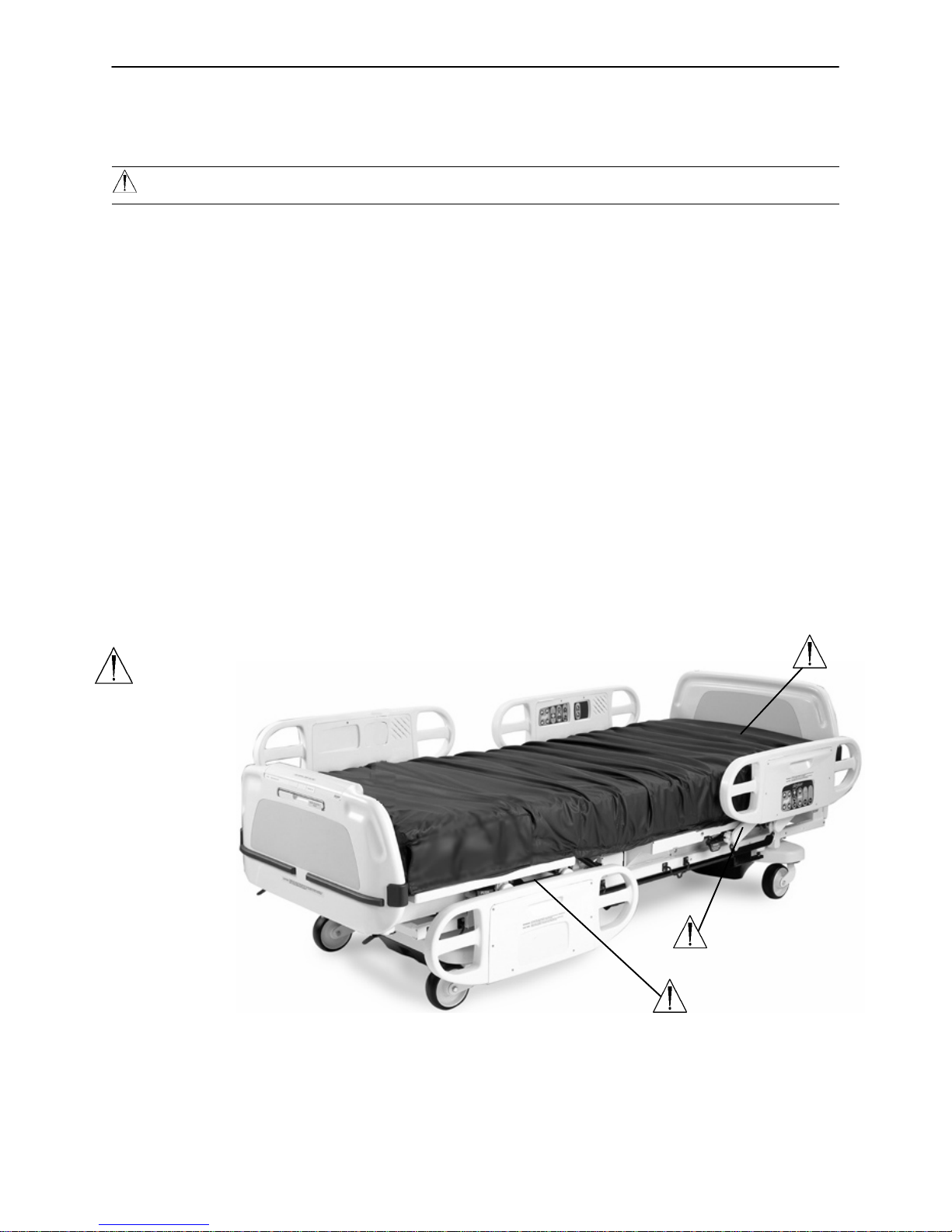
This manual is designed to assist you with the maintenance of the Stryker Model 2040 Zoom Patient Transport Frame. Read it thoroughly before using the equipment or beginning any maintenance on it.
SPECIFICATIONS
Safe Working Load 500 pounds (227 kilograms)
Scale System Capacity (optional equipment) Loads weighing up to 500 pounds (227 kilograms)
Scale System Accuracy (optional equipment) $1 pound of total patient weight at any bed position
(patients weighing 100 pounds or less)
$1% of total patient weight at any bed position
(patients weighing greater than 100 pounds)
Overall Length/Width L−93” /W−42.5” or
L−238 cm /W−108 cm
Minimum/Maximum Height (Standard)
Minimum/Maximum Height (Enhanced)
Fluoro Access 16”
Knee Gatch Angle 0 to 30
Back Angle 0 to 90
Trendelenburg/Reverse Trendelenburg +10 to −12 $1
Electrical Requirements 115 VAC, 60 Hz, 7.0 Amps
Battery Voltage 24 V, 31 Ah
Outlet Option 125 VAC, 5A, 60 Hz
18” to 32.5” $0.5 / 46 cm. to 82.5 cm.
19.5” to 34.5” $0.5 / 49.5 cm. to 88 cm.
(Add 2 inches if the bed has 8” casters.)
If the bed is equipped with the enhanced height option, the scale accuracy is as described above for litter angles from 0 to $ 5 Trend.
Stryker reserves the right to change specifications without notice.
WARNING / CAUTION / NOTE DEFINITION
WARNING
Alerts the reader about a situation, which if not avoided, could result in death or serious injury. It may also
describe potential serious adverse reactions and safety hazards.
CAUTION
Alerts the reader of a potentially hazardous situation, which if not avoided, may result in minor or moderate
injury to the user or patient or damage to the equipment or other property. This includes special care necessary for the safe and effective use of the device and the care necessary to avoid damage to a device that
may occur as a result of use or misuse.
NOTE
This provides special information to make maintenance easier or important instructions clearer.
4
Page 6

Introduction
SAFETY TIPS AND GUIDELINES
Before operating the 2040 Patient Transport Frame, it is important to read and understand all information in
this manual. Carefully read and strictly follow the safety guidelines listed on this page. To ensure safe operation of the transport frame, methods and procedures must be established for educating and training hospital
staff on the intrinsic risks associated with the usage of motorized electric units.
WARNING
The 2040 Patient Transport Frame is equipped with a hospital grade plug for protection against shock
hazard. It must be plugged directly into a properly grounded three−prong receptacle. Grounding reliability can be achieved only when a hospital grade receptacle is used.
Serious injury can result if caution is not used when operating the unit. Operate the unit only when all
persons are clear of the electrical and mechanical systems.
Leave the frame in the lowest position when the patient is unattended. Leaving the frame in a raised posi-
tion could increase the chance of patient falls and injury.
When raising the siderails, listen for the ”click” that indicates the siderail has locked in the up position.
Pull firmly on the siderail to ensure it is locked into position. Siderails are not intended to be a patient
restraint device. It is the responsibility of attending medical personnel to determine the degree of restraint
and the siderail positioning necessary to ensure a patient will remain safely in bed.
Always apply the caster brakes when a patient is getting on or off the bed. Always keep the caster brakes
applied when a patient is on the bed (except during transport). Injury could result if the bed moves while
a patient is getting in or out of bed.
Ensure the brakes are completely released prior to attempting to move the unit. Attempting to move the
unit with the brakes actuated could result in injury to the user and/or patient.
Put the drive wheel in the neutral position and release the brakes before pushing the unit manually. Do
not attempt to push the unit manually with the drive wheel engaged. The unit will be difficult to push and
injury could result.
The CPR emergency release requires assistance to lower the Back if the angle of the Back is above 80.
Attempting to lower the Back in this position without assistance may result in injury to the operator.
The power save mode is activated after one hour on battery power with no motion release switch activa-
tion. Functions including Bed Exit, scale and motion will cease to operate when the unit enters the power
save mode. Injury to the patient could occur if proper patient monitoring protocol is not observed.
The Bed Exit System is intended only to aid in the detection of a patient exiting the unit. It is NOT intended
to replace patient monitoring protocol. The bed exit system signals when a patient is about to exit. Adding
or subtracting objects from the frame after arming the bed exit system may cause a reduction in the sensitivity of the bed exit system.
To avoid pinching your fingers, place the IV pole in the upright position before using the drive handle.
Always unplug the power cord and push the battery power on/off switch to the “OFF” position before ser-
vice or cleaning. When working under the frame, always place blocks under the litter frame to prevent
injury in case the Bed Down switch is accidently activated.
Battery posts, terminals and related accessories contain lead and lead compounds, chemicals known
to the State of California to cause cancer and birth defects or other reproductive harm. Wash hands after
handling.
The 2040 Patient Transport Frame is intended for use by trained hospital personnel only.
Warning: Service only by qualified personnel. Refer to maintenance manual.
Do not modify the 2040 Patient Transport Frame. Modifying the unit can cause unpredictable operation
resulting in injury to the patient or operator. Modifying the unit will also void its warranty.
5
Page 7

Introduction
SAFETY TIPS AND GUIDELINES (CONTINUED)
WARNING
To avoid possible injury and to assure proper operation when using a powered mattress replacement system
such as XPRT:
Confirm proper scale system operation following mattress installation. For best results, secure the thera-
py mattress power cord to prevent damage to the cord or interference with the bed frame and the scale
system.
Do not zero bed scales or weigh patient with Percussion, Vibration, Rotation or Turn−Assist active. Pa-
tient motion and position resulting from the dynamic therapy mattress may adversely affect scale system
performance.
Do no initialize (“arm”) bed exit with Percussion, Vibration, Rotation or Turn−Assist active. The patient
motion and position resulting from the dynamic therapy mattress may adversely affect bed exit system
performance.
CAUTION
Use caution while maneuvering the unit with the drive wheel activated. Always ensure there are no ob-
stacles near the unit while the drive wheel is activated. Injury to the patient, user or bystanders or damage
to the frame or surrounding equipment could occur if the unit collides with an obstacle.
Use caution when transporting the unit down halls, through doors, in and out of elevators, etc. Damage
to the siderails or other parts of the unit could occur if the unit comes in contact with walls or door frames.
If unanticipated motion occurs, unplug the power cord from the wall socket, push the battery power on/off
switch to the ”OFF” position (the LED will not be illuminated) and actuate the drive wheel pedal to the
neutral position.
The siderails are not intended to be used as a pushing device. Damage to the siderails could occur.
The use of a mattress overlay may reduce the effectiveness of the siderail.
When attaching equipment to the frame, ensure it will not impede normal operation. I.E.: hooks on hang-
ing equipment must not actuate control buttons, equipment must not hide the nurse call button, etc.
Use caution when lowering the bed with items attached to the optional accessory rail. If caution is not
used, items may contact the floor resulting in damage to the items and/or injury to the patient or user.
The lockout buttons on the foot board lock the Fowler, Gatch and Bed Up/Down functions and prevent
motion of the bed. It is the responsibility of attending medical personnel to determine whether these functions should be locked and to use the buttons accordingly.
Scale function may be affected by siderail/caster interference. With the litter fully lowered or lowered in
Reverse Trendelenburg, the siderails tucked under the litter in the storage position and the casters
turned, there is the potential for interference between the siderail and the caster. Raise the siderails when
lowering the litter to the full down position to prevent the interference from causing the bed’s scale system
to weigh inaccurately.
If large fluid spills occur in the area of the circuit boards or motors, immediately unplug the power cord
from the wall socket and push the battery power on/off switch to the “OFF” position. Remove the patient
from the unit and clean up the fluid. Have maintenance completely check the unit. Fluids can short out
controls and may cause the unit to operate erratically or make some functions completely inoperable.
Component failure caused by fluids could even cause the unit to operate unpredictably and could cause
injury to the patient. DO NOT put the unit back into service until it is completely dry and has been thoroughly tested for safe operation.
6
Page 8
Introduction
SAFETY TIPS AND GUIDELINES (CONTINUED)
CAUTION
Preventative maintenance should be performed at a minimum of annually to ensure all features are func-
tioning as designed. Close attention should be given to safety features including, but not limited to:
Safety side latching mechanisms Caster braking systems
Leakage current 300 microamps max. No controls or cabling entangled in frame mechanisms
Frayed electrical cords and components All controls return to off or neutral position when released
The battery tray assembly weighs 50 pounds. Take care when removing the two hex head screws secur-
ing it to the base frame or personal injury could result.
The 2040 Patient Transport Frame is not intended for pediatric use or for patients under 50 pounds.
Because individual beds may have different options, foot boards should not be moved from one bed to
another. Interchanging foot boards between beds could result in unpredictable bed operation.
The weight of the IV bags should not exceed 40 pounds.
The following Caution statements apply to the optional 110V outlet:
Maximum total load 5A receptacle rating: 125VAC, 5A, 60Hz.
The total system chassis risk current should not exceed 300uA
Grounding continuity should be checked periodically.
Do not use for life−sustaining equipment.
Use only hospital−grade equipment with electrical outlet.
Unplug free−standing equipment before transporting the bed.
WARNING
Potential pinch points
7
Page 9

Introduction
SET−UP PROCEDURES
It is important that the 2040 Patient Transport Frame is working properly before it is put into service. The
following list will help ensure that each part of the transport frame is checked.
Plug the power cord into a properly grounded, hospital grade wall receptacle.
WARNING
The 2040 Patient Transport Frame is equipped with a hospital grade plug for protection against shock hazard.
It must be plugged directly into a properly grounded three−prong receptacle. Grounding reliability can be
achieved only when a hospital grade receptacle is used.
Depress the pedal at either side of the transport frame fully to set the four wheel brakes and ensure all
four casters lock. Depress the pedal again to release the brakes.
Ensure the siderails raise and lower smoothly and lock in the up and intermediate positions.
Run through each function on the foot board control panel and ensure that each is working properly.
Ensure all functions are working properly on the siderail controls.
Ensure all motion functions are working properly at the head end of the transport frame.
Raise the Back up to approximately 60. Squeeze the CPR release handle and ensure the Back and
Knee will drop with minimal effort.
Unplug the power cord from the wall socket. Push the battery power switch located on the lower left cor-
ner of the head end to the “ON” position. Again, verify each function on the foot board and siderails is
operating properly.
With the battery power switch in the “ON” position and the brakes engaged, ensure the “Release Brakes”
LED on the head end control panel is illuminated.
With the battery power switch in the “ON” position and the drive wheel disengaged (not touching the floor),
ensure the “Engage Drive Wheel” LED on the head end control panel is illuminated.
Run through the operation of the drive wheel to ensure it is operating properly.
If the bed is equipped with the Nurse Call option, verify it is functioning properly prior to patient use.
8
Page 10

BED SYMBOLS
Warning, Refer to Service/Maintenance Manual
Introduction
~
Alternating Current
Type B Equipment: equipment providing a particular degree of protection against electric shock, particularly regarding allowable leakage current and reliability of the protective earth connection.
Class 1 Equipment: equipment in which protection against electric shock does not rely
on BASIC INSULATION only, but which includes an additional safety precaution in that
means are provided for the connection of the EQUIPMENT to the protective earth conductor in the fixed wiring of the installation in such a way that ACCESSIBLE METAL
PARTS cannot become live in the event of a failure of the BASIC INSULATION.
Mode of Operation: Continuous
IPX4: Protection from liquid splash
Dangerous Voltage Symbol
Protective Earth Terminal
Potential Equalization Symbol
Medical Equipment Classified by Underwriters Laboratories Inc. with Respect to Electric Shock, Fire, Mechanical and Other Specified Hazards Only in Accordance with UL
2601−1 and CAN/CSA C22.2 No. 601.1
Safe Working Load
9
Page 11
BED SYMBOLS (CONTINUED)
Introduction
1
UP
2
DOWN
7
ENGAGE DRIVE WHEEL
9
PLUG BED IN TO CHARGE
3
KNEE BACK
4
8
RELEASE BRAKES
5
6
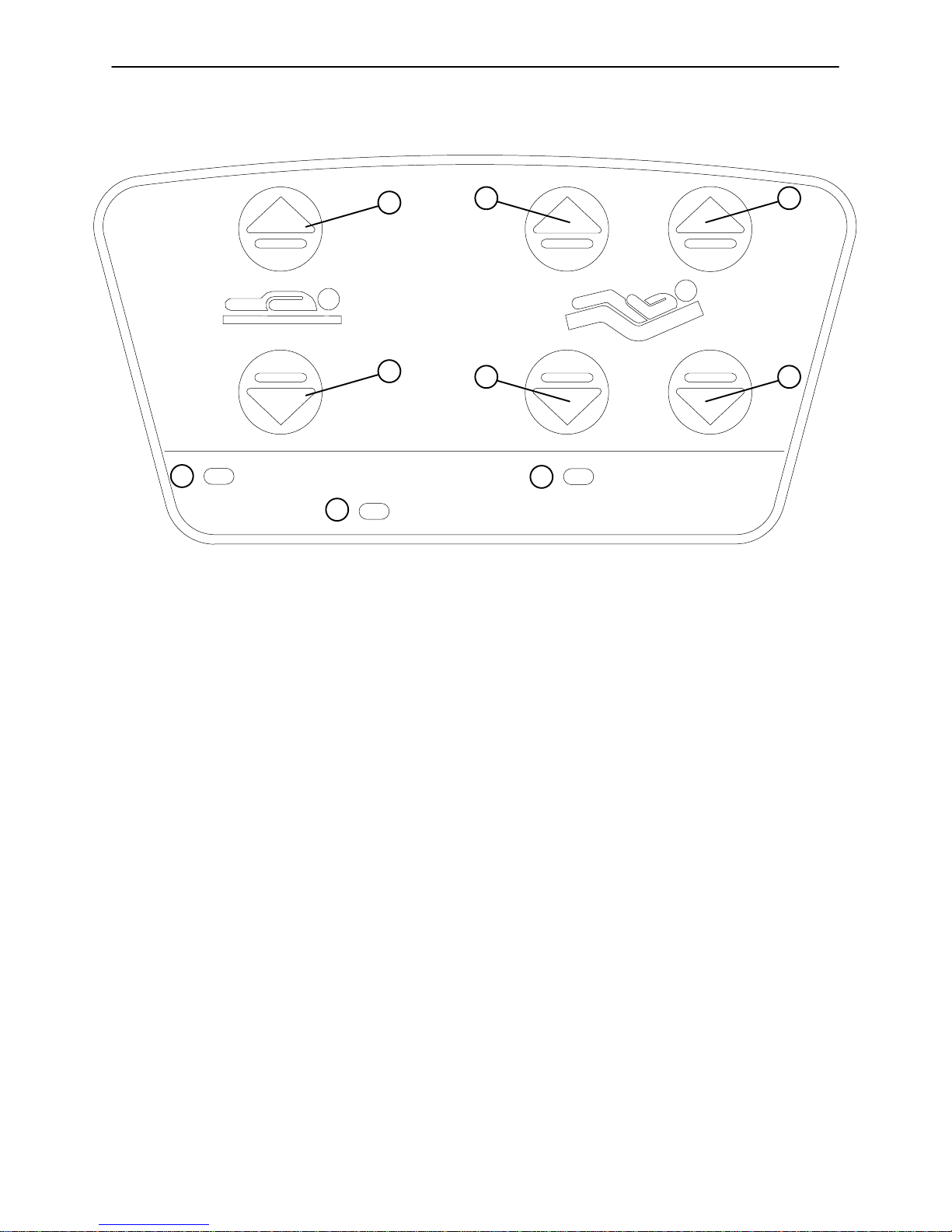
1. Press and hold to raise the litter. If your bed is equipped with the enhanced height option, continue to
hold the button an additional 5 seconds after the first stop. The litter will raise an additional 2 inches.
2. Press and hold to lower the litter
3. Press to raise the Knee section.
4. Press to lower the Knee section.
5. Press to raise the Back section.
6. Press to lower the Back section.
7. The “Engage Drive Wheel” LED will be illuminated whenever the battery power switch is on and the drive
wheel pedal is in the disengaged position. The light will go off when the drive wheel is engaged.
8. The “Release Brakes” LED will be illuminated whenever the frame’s brakes are engaged while the battery
power switch is on. The light will go off when the brakes are disengaged.
9. The “Plug Bed In To Charge” LED will be illuminated while the battery power switch is on if the battery
level is low. Plug the power cord into the wall socket to charge the batteries.
10
Page 12
BED SYMBOLS (CONTINUED)
Introduction
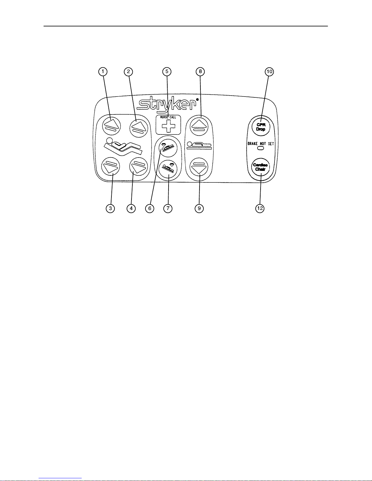
1. Press to raise back section.
2. Press to raise knee section.
3. Press to lower back section.
4. Press to lower knee section.
5. Press to activate nurse call.
6. Press to lower the head end (Trendelenburg).
7. Press to lower the foot end (Reverse Trendelenburg).
8. Press to raise the litter. If your bed is equipped with the enhanced height option, continue to hold the
button an additional 5 seconds after the first stop. The litter will raise an additional 2 inches.
9. Press to lower the litter.
10. Press to activate emergency CPR positioning.
11. Press to activate Cardiac Chair positioning.
11
Page 13
BED SYMBOLS (CONTINUED)
Introduction
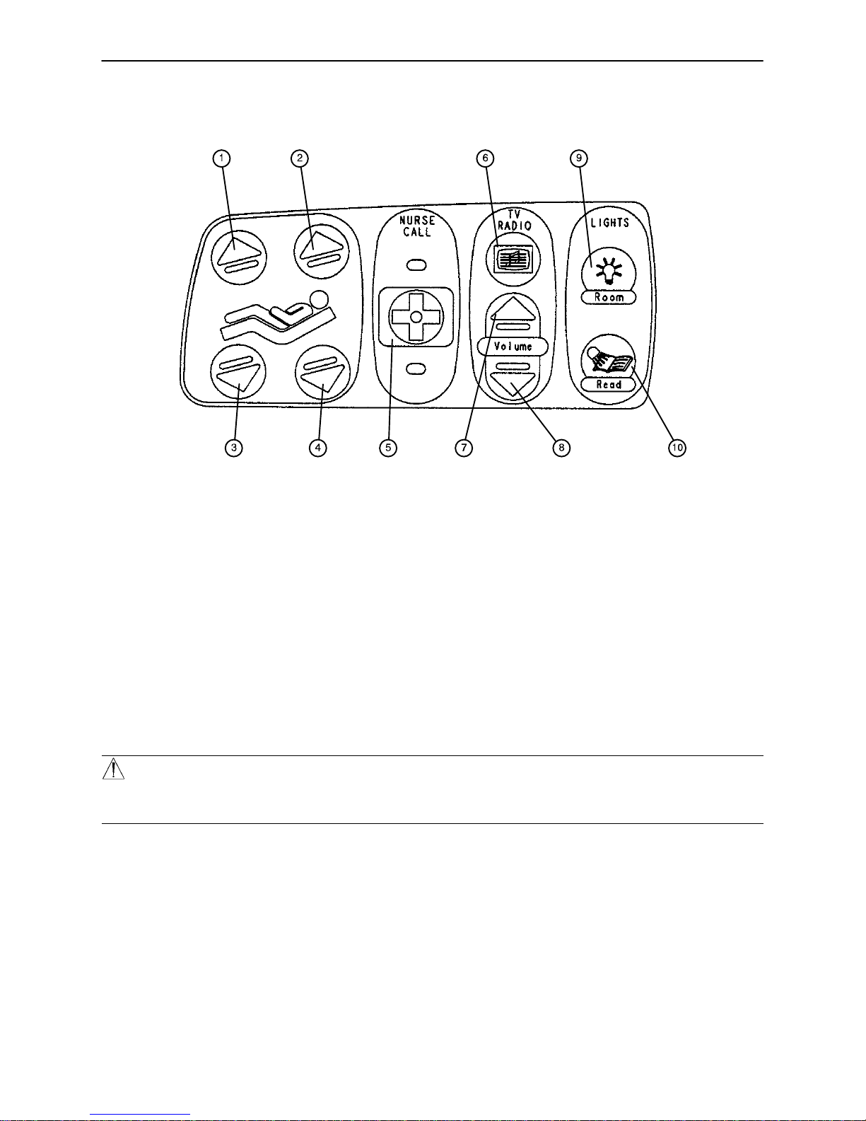
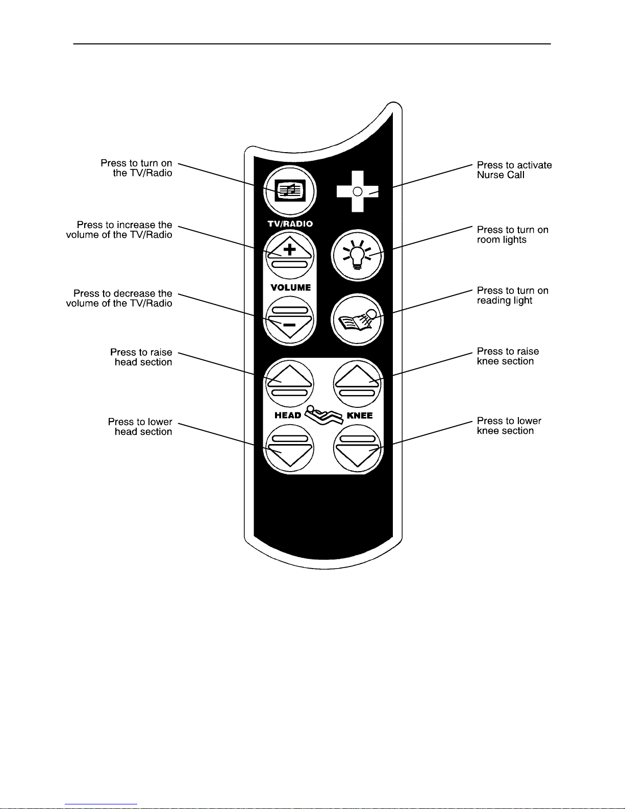
1. Press to raise knee section.
2. Press to raise back section.
3. Press to lower knee section.
4. Press to lower back section.
5. Press to activate the nurse call.
6. Press to turn on the TV or radio. Press again to change TV channels and to turn off the TV.
7. Press to increase the TV or radio volume.
8. Press to decrease the TV or radio volume.
9. Press to turn on the room lights. Press again to turn off.
10. Press to turn on the reading light. Press again to turn off.
WARNING
Because individual beds may have different options, foot boards should not be moved from one bed to another. Mixing foot boards could result in unpredictable bed operation.
12
Page 14
Introduction
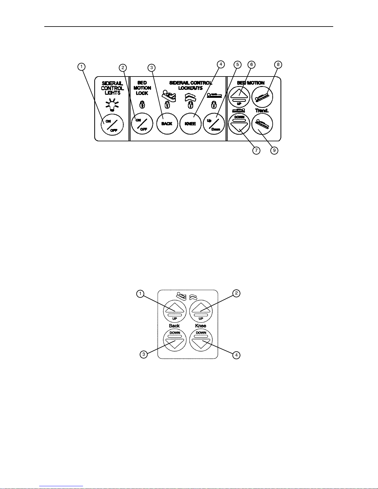
BED SYMBOLS (CONTINUED)
1. Press repeatedly for low, medium and high settings for the siderail control lights. Continue to press this
switch to turn off the siderail control lights and the nurse call indicator light.
2. Press to lock out all motion controls on the siderails. Press again to unlock.
3. Press to lock out Back motion control on the siderails. Press again to unlock.
4. Press to lock out Knee motion control on the siderails. Press again to unlock.
5. Press to lock out up/down motion controls on the siderails. Press again to unlock.
6. Press to raise litter. If your bed is equipped with the enhanced height option, continue to hold the
button an additional 5 seconds after the first stop. The litter will raise an additional 2 inches.
7. Press to lower litter.
8. Press to lower head end (Trendelenburg).
9. Press to lower foot end (Reverse Trendelenburg).
1. Press to raise back section.
2. Press to raise knee section.
3. Press to lower back section.
4. Press to lower knee section.
13
Page 15
Introduction
BED SYMBOLS (CONTINUED)
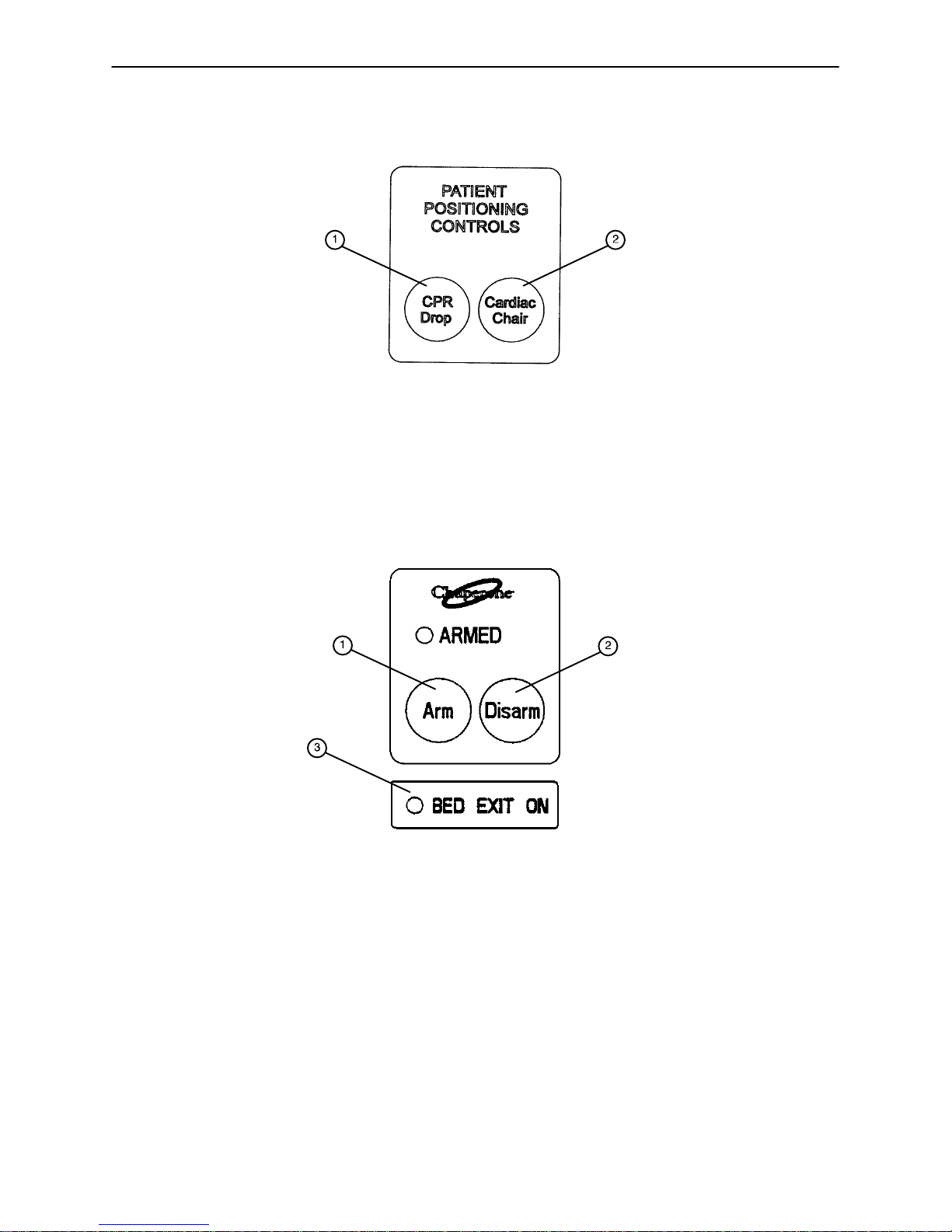
1. Press to activate the emergency CPR function. The Back will lower to flat, the Knee will lower to flat, the
litter will level from Trendelenburg/reverse Trendelenburg, and the litter will lower to full down.
2. Press to activate the Cardiac Chair function. The Knee will raise, the Fowler will raise or lower to approximately 52 and the bed will tilt to approximately −12 reverse Trendelenburg (foot end down) or −14
if the bed has the enhanced height option. Release the button to stop bed movement: hold the button
until movement stops to complete the function.
1. Press to arm the Bed Exit function.
2. Press to disarm the Bed Exit function.
3. “BED EXIT ON” LED − will light when the BED EXIT function is armed.
14
Page 16
Introduction
BED SYMBOLS (CONTINUED)
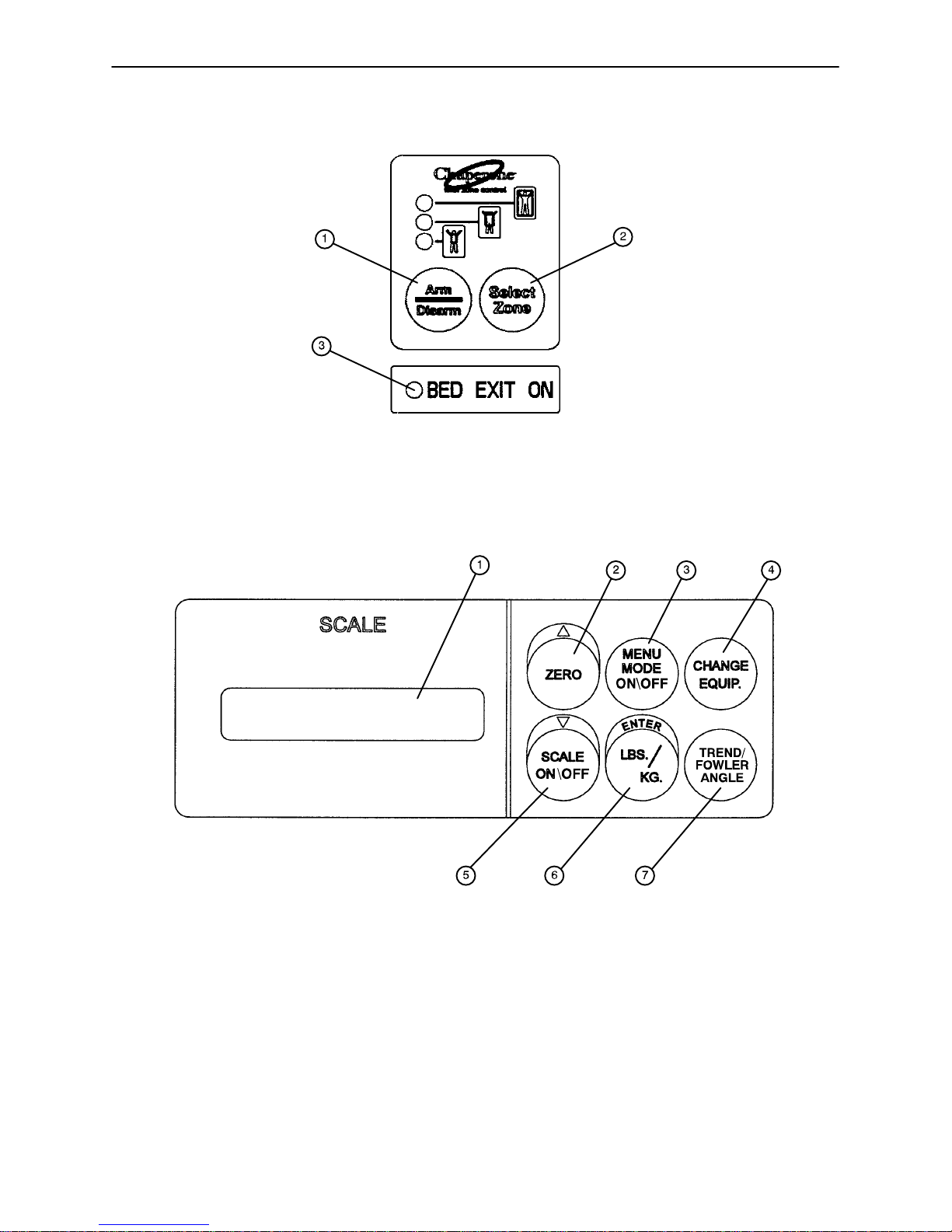
1. Press to arm or disarm the Bed Exit function.
2. Press to select the zone desired for Bed Exit function.
3. “BED EXIT ON” LED − will light when the BED EXIT function is armed.
1. LCD − displays patient weight. Trendelenburg angle is displayed when the scale is not active.
2. Press to zero system. Also press to scroll while Menu Mode is active.
3. Press to enter and exit the Menu Mode.
4. Press when adding or removing equipment on the frame.
5. Press to turn weigh system on and off. Also press to scroll while Menu Mode is active.
6. Press to change weight from pounds to kilograms or back. Also press while using the Menu Mode.
7. Press to display the Trendelenburg or Fowler angle.
15
Page 17
BED SYMBOLS (CONTINUED)
Introduction
16
Page 18

Preventative Maintenance
CLEANING
Hand wash all surfaces of the bed with warm water and mild detergent. DRY THOROUGHLY. Do not steam
clean or hose off the Zoom Bed. Do not immerse any part of the bed. Some of the internal parts of the bed
are electric and may be damaged by exposure to water.
Suggested cleaners for bed surfaces:
Quaternary Cleaners (active ingredient − ammonium chloride)
Phenolic Cleaners (active ingredient − o−phenyl phenyl)
Chlorinated Bleach Solution (5.25% − less than 1 part bleach to 100 parts water)
Avoid over−saturation and ensure the product does not stay wet longer than the chemical manufacturer’s
guidelines for proper disinfecting.
CAUTION
SOME CLEANING PRODUCTS ARE CORROSIVE IN NATURE AND MAY CAUSE DAMAGE TO THE
PRODUCT IF USED IMPROPERLY. If the products described above are used to clean Stryker patient care
equipment, measures must be taken to insure the beds are wiped with clean water and thoroughly dried following cleaning. Failure to properly rinse and dry the beds will leave a corrosive residue on the surface of
the bed, possibly causing premature corrosion of critical components. Failure to follow the above directions
when using these types of cleaners may void this product’s warranty.
For mattress cleaning instructions, please see the tag on the mattress, or contact the mattress manufacturer.
Clean Velcro AFTER EACH USE. Saturate Velcro with disinfectant and allow disinfectant to evaporate.
(Appropriate disinfectant for nylon Velcro should be determined by the hospital.
17
Page 19

Preventative Maintenance
CHECKLIST
All fasteners secure
Engage brake pedal and push on the frame to ensure all casters lock securely
Optional locking steer caster engages and disengages properly
Engage drive wheel and ensure it is operating properly
Motion release switches working properly
Confirm Head End Control Panel functionality
Confirm battery powered functionality
Siderails move, latch and stow properly
All functions on siderails working properly (including LED’s)
Manual CPR release working properly
Foot prop intact and working properly
I.V. pole working properly
Foley bag hooks intact
Chart rack intact and working properly
CPR board not cracked or damaged and stores properly
No cracks or splits in head and foot boards
All functions on footboard working properly (including LED’s)
No rips or cracks in mattress cover
Scale and Bed Exit system calibrated properly
Power cord not frayed
No cables worn or pinched
All electrical connections tight
All grounds secure to the frame
Ground impedance not more than 100 milliohms
Current leakage not more than 300 microamps
Apply grease to litter grease points
Fowler functioning properly
Unit Serial No.
Completed By:_________________________________ Date:_____________
18
Page 20

Preventative Maintenance
WARNING
Service only by qualified personnel. Refer to the maintenance manual.
Ensure the power cord is unplugged and the battery power switch is turned to the off position before servicing.
NURSE CALL BATTERY
To prevent a low battery condition when the power cord is not plugged in, position the cord out switch at the
head end to the off position. The switch is identified by the label shown below. If the switch is not positioned
as shown below and the power cord and pendant cord are unplugged, the life of the back−up battery will be
significantly reduced.
If the foot board POWER LED is flashing, the Nurse Call battery needs to be replaced. The battery is located
on the patient’s left side under the litter frame. No tools are required to replace the battery. Unplug the power
cord from the wall socket and replace the battery. After replacing the battery, verify the foot board POWER
LED is no longer flashing. Properly dispose of the old battery in accordance with local regulations.
MAIN POWER CIRCUIT BREAKER
In the event of a loss of electric function, unplug the power cord from the wall socket and reset the circuit
breaker(s) located under the head end of the litter on the patient’s left side. Plug the power cord into a properly
grounded wall receptacle and follow the set−up procedures listed on page 8.
BATTERY CHARGER CIRCUIT BREAKER
If the battery charger circuit breaker(s) located under the litter on the patient’s head end, left side are tripped,
refer to the troubleshooting section of the maintenance manual.
19
Page 21
Static Discharge Precautions
The electronic circuits in the 2040 are completely protected from static electricity damage only while the bed
is assembled. It is extremely important that all service personnel always use adequate static protection when
servicing the electronic systems of the Secure II. Whenever you are touching wires, you should be using
static protection.
Static Protection Equipment
The necessary equipment for proper static protection is:
1 static wrist strap; 3M part number 2214 or equivalent,
1 grounding plug; 3M part number 61038 or equivalent,
1 test lead with a banana plug on one end and an alligator clip on the other; Smith part number
N132B699 or equivalent.
CAUTION
All electronic service parts will be shipped in static shielding bags. Do not open the bags until you have completed steps 2 and 3 of the following procedure. Do not place unprotected circuit boards on the floor. All circuit
boards to be returned to Stryker Medical should be shipped in the static shielding bags the new boards were
shipped in.
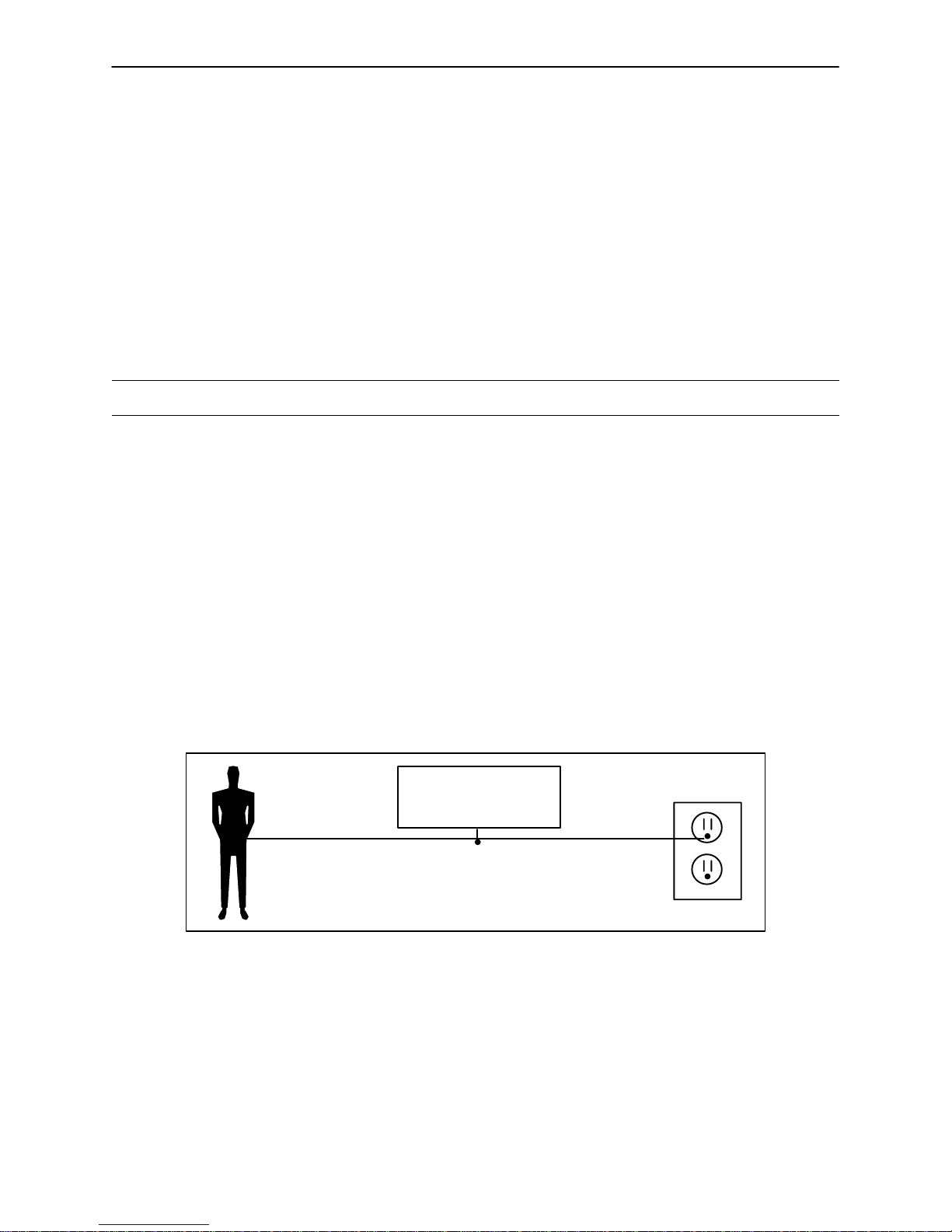
Static Protection Procedure
1. Unplug the power cord from the wall receptacle.
2. Insert the grounding plug into a properly grounded hospital grade wall receptacle. Plug the banana plug
of the test lead into the receptacle on the grounding plug. Connect the alligator clip on the other end of
the test lead to a ground point on the bed.
3. Place the static control wrist strap on your wrist. Connect the alligator clip at the other end of the wrist strap
cord to a ground point on the bed.
BED
GROUNDING DIAGRAM
20
Page 22

Troubleshooting Guide
NOTE
See page 28 through page 37 for an outline of bed PCB’s and voltage test points.
PROBLEM/FAILURE RECOMMENDED ACTION
No power to bed A. Verify the power cord connections at the wall and the bed.
B. Check circuit breakers, under the litter/gatch section on the
patient left side. If the circuit breaker is tripped, reset it by
pushing in.
C. Check for 120 VAC at J1 on the power supply, Pin 1 and 2.
D. Check for DC voltages on J2 (Pins 1, 2, 3 & 6) on power
supply. See page 33 for power supply voltage test points.
a. If voltage is present, check connector W on the CPU board
and check for the same DC voltages. If OK, go to step E.
b. If voltage is not present, unplug connector W on the CPU
board and recheck for DC voltages at J2 on the power
supply.
1. If voltages come back, re−connect cable W to the CPU
board, and go to step c.
2. If DC voltage does not come back, replace the power
supply.
c. Unplug all connectors except for F, FF, O, and W from the
CPU board and recheck voltages on connector W
1. If DC voltages come back, plug the cable connections
back in until problem comes back, isolate the problem to
a component or assembly.
2. If DC voltages do not come back, replace the CPU board
E. Check for 120 VAC at connector O on the CPU board.
a. If voltage is present, replace the CPU board.
F. Verify bed function and return to service.
No bed down motion. A. Enter diagnostics, (see page 55) and press bed down.
a. If motion is not present, verify there is a two−pin shunt
present on connector Z, closest to the center of the bed, if
not, install shunt.
1. Test bed down motion, if motion is present then go to step
D.
b. If motion is present, re−burn lift potentiometer limits, see
page 48 for procedure.
B. Check for 5 VDC on TP 9 (HL) and TP 7 (FL).
a. If 5 VDC is present, go to step C.
b. If 5 VDC is not present, replace CPU board.
C. Check for 120 VAC power on connector N (HL) and G (FL),
pin 1 white and pin 3 black, of the CPU board, while pressing
bed motion up.
a. If voltage is not present, replace CPU board.
b. If voltage is present:
1. Verify the motors are running, if so, replace lift couplers.
2. If motors are not running, check voltage at motor
connection.
3. If voltage is present at motor, check capacitors or motors.
D. Verify bed function and return to service.
21
Page 23

Troubleshooting Guide
PROBLEM/FAILURE
No bed up motion. A. Enter diagnostics, (see page 55) and press bed up.
a. If motion is not present, go to step B.
b. If motion is present, re−burn lift potentiometer limits, see
page 48 for procedure.
B. Check for 5VDC on TP 10 (HL) and TP 8 (FL) on the CPU
board
a. If 5 VDC is present, go to step C.
b. If 5 VDC is not present, replace CPU board.
C. Check for 120 VAC power on connector N (HL) and G (FL),
pin 1 white and pin 6 red, of the CPU board while pressing bed
motion up.
a. If voltage is not present, replace CPU board.
b. If voltage is present
1. Verify the motors are running, if so, replace lift couplers.
2. If motors are not running, check voltage at motor
connection.
3. If voltage is present at motor, check capacitors or motors.
D. Verify bed function and return to service.
No Gatch down motion. A. Check for 5VDC on TP 5 on the CPU board
a. If 5 VDC is present, go to step B.
b. If 5 VDC is not present, replace CPU board.
B. Check for 120 VAC power on connector CC, pin 2 (red) and
pin 3 (white), of the CPU board while pressing gatch down.
a. If voltage is not present, replace the CPU board
b. If 5 VDC is present, check the capacitor and motor.
C. Verify bed function and return to service.
No Gatch up motion. A. Check for 5 VDC on TP 6 on the CPU board
a. If 5 VDC is present, go to step B.
b. If 5 VDC is not present, replace CPU board.
B. Check for 120 VAC on connector CC, pin 1 (black) and pin
3 (white), of the CPU board while pressing gatch up.
a. If voltage is not present, replace the CPU board
b. If 5 VDC is present, check the capacitor and motor.
C. Verify bed function and return to service.
No Fowler up/or uneven motion. A. Check for 5 VDC on TP 3 on the CPU board
a. If 5 VDC is present, go to step B.
b. If 5 VDC is not present, replace CPU board.
B. Check for 120 VAC on connector GG, Pin 1 (white) and pin
2 (black), of the CPU board while pressing Fowler up.
a. If voltage is not present, replace the CPU board
b. If 5 VDC is present, check the capacitor and motor.
C. Refer to Fowler Mechanism Customer Guide
(2030-009-028)
D. Verify bed function and return to service.
No Fowler down/or uneven motion. A. Check for 5VDC on TP4 on the CPU board
a. If 5 VDC is present, go to step B.
b. If 5 VDC is not present, replace CPU board.
B. Check for 120 VAC on connector GG, Pin 1 (white) and pin
3 (red), of the CPU board while pressing Fowler up.
a. If voltage is not present, replace the CPU board
b. If 5 VDC is present, check the capacitor and motor.
C. Refer to Fowler Mechanism Customer Guide
(2030-009-028)
D. Verify bed function and return to service.
RECOMMENDED ACTION
22
Page 24

Troubleshooting Guide
This section of the troubleshooting guide includes the Zoom self−propelled drive and the battery backup
functions. When using this guide, assume the bed is functioning properly when powered by the AC line cord
with the exception of the battery charging components.
PROBLEM/FAILURE POSSIBLE CAUSE RECOMMENDED ACTION
ON/OFF switch is in the on position
but the power LED is off and the bed
does not function.
ON/OFF switch is in the on position,
the power LED is on but the bed
does not function.
ON/OFF switch is in the on position,
the power LED is on, the Zoom
drive works but the battery backup
does not work.
The Zoom drive does not work −
the bed does not drive − but all other
functions are working.
No DC voltage from the batteries. A. Check the fuse (F1) on the power
board (see page 37) − replace if necessary (p/n 59−730).
B. Verify the battery voltage is greater
than 24 VDC.
C. Check the battery fuse − replace if nec-
essary (p/n 2040−1−802).
D. Check the cable connections from the
batteries to the display board.
E. Check the ON/OFF switch and cabling.
Display board is not functioning or
is locking out all functions.
The thermostat on the inverter/
charger board has tripped, indicating a temperature above 110
C (230 F).
Zoom drive circuitry is not responding.
A. Check the safety switches on the drive
bar.
B. Verify the battery voltage is greater
than 24 VDC.
C. Verify the display board is functioning
(see note below).
D. Check all cable connections on the display and power boards.
A. Wait approximately 3−5 minutes to al-
low the inverter/changer board to cool
down.
A. Verify the display board is functioning
(see note below).
B. Perform the control bar potentiometer
“burn−in” procedure (see page 66).
C. Check the control bar potentiometer.
When the bar is centered, there should be
2.25VDC − 2.75 VDC between pin 1 and
pin 2 on header 1 on the display/CPU
board (see page 35)
D. Check all cable connections on the display and power boards.
E. Verify the power board is functioning.
F. Verify the drive wheel is functioning.
NOTE
The display board will display the state of battery charge when the bed is first powered using the ON/OFF switch:
Three LED’s flash = 66% − 100% charged
Two LED’s flash = 33% − 66% charged
One LED flashes = less than 33% charged
No LED’s flash = no significant charge remaining.
23
Page 25

Troubleshooting Guide
PROBLEM/FAILURE POSSIBLE CAUSE RECOMMENDED ACTION
The Zoom drive does work − the
bed will drive − but all other bed
functions are not working.
No AC power from the Zoom
base.
A. Check AC voltage coming out of the inverter. It should be 120VAC between pin
1 and pin 4 on header 5 on the AC crossover board (see page 36)
B. Check all cable connections from the
batteries to the converter.
C. Check the AC crossover board.
The bed power cord is plugged in
but the battery does not charge.
The battery charger is not functioning.
A. Check the circuit breakers on the
Zoom litter (page 118, item NA) .
B. Check the battery charger.
C. Check all cable connections on the
charger.
24
Page 26
Troubleshooting Guide
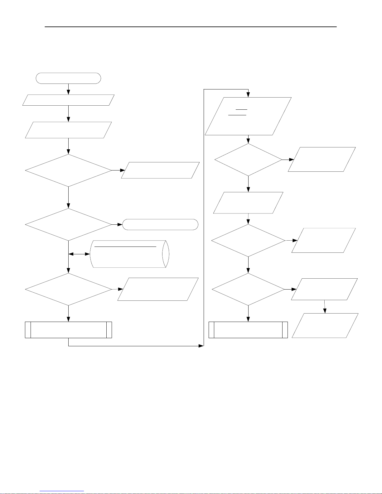
INVERTER/CHARGER, BATTERY & ZOOM TROUBLESHOOTING GUIDE
Start
Bed is not working
Put ON/OFF Switch in
ON position
Is the Power LED ON ?
Yes
Is
at least one LED Flashing
during start−up process
?
Yes
Are all the Non−Zoom
functions working ?
No
No
Ref. Battery and Charger Module
Display board: Battery status
3 LED’s Flash: >66 %
2 LED’s Flash: 33−66%
1 LED Flash: <33%
No
Refer to Bed
Troubleshooting GUide
Check Fuse F1 in
Power supply board:
Replace Inverter/
Charger assembly
Put the Bed in
Drive mode
Release the Brake
Squeeze the
Handle Bar
switches
Is the Bed moving
No
Push/Pull the
Zoom Handle
Bar
Is the Bed driving in
opposite directions
?
No
Is the Zoom
working properly?
Yes
Yes
No
Recalibrate the
Potentiometer
(Control bar
POT Burn−in)
Check the
Motor wire
connectors
reversal
Check the
Battery wire
connectors
reversal
Yes
Inverter is Good
25
Yes
Zoom is Good
Replace
Inverter/
Charger
assembly
Page 27
Troubleshooting Guide
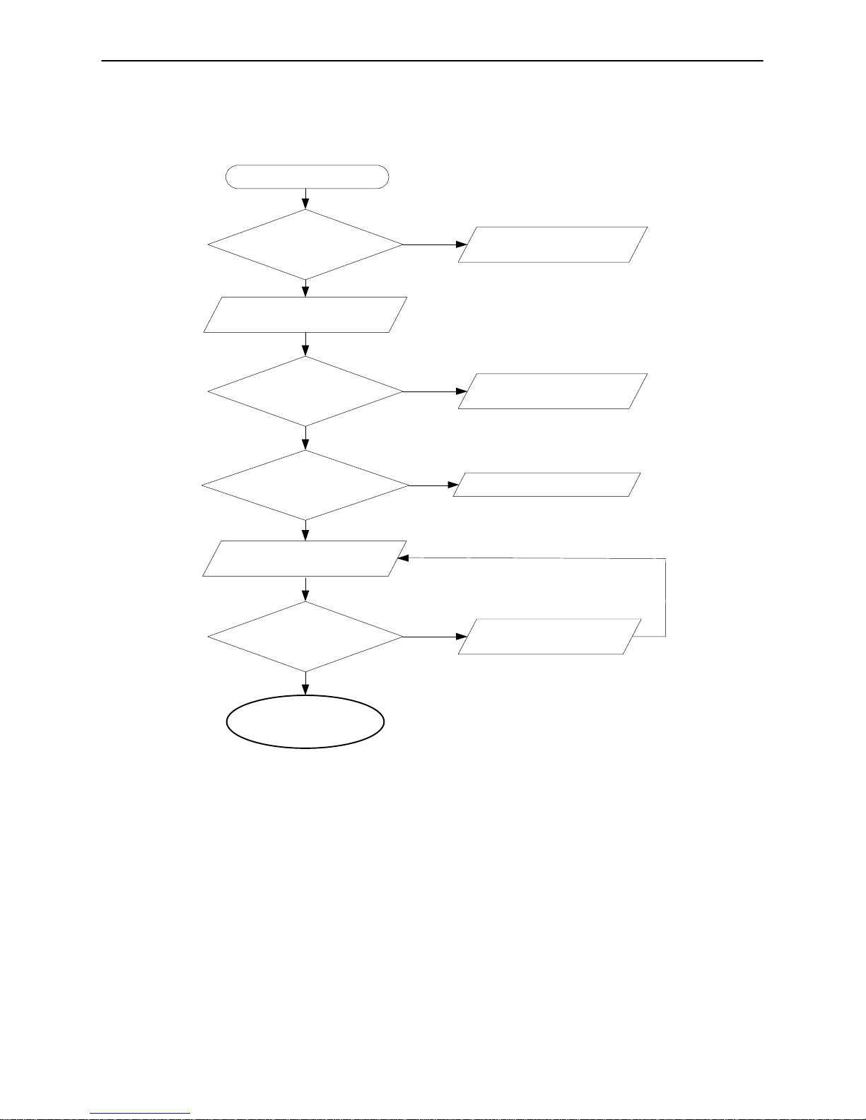
INVERTER/CHARGER, BATTERY & ZOOM TROUBLESHOOTING GUIDE
Battery and Charger Module
Is the Input supply Voltage
(~120V AC) Good?
Yes
Connect Bed to
Wall Power (~120V AC)
Are the Circuit Breakers OK ?
Yes
Is Battery Volage Sufficient?
(> 21VDC)
Yes
Plug Bed into Wall Socket
(For Charging/Test)
Is the Battery Voltage
Increasing?
No
No
No
No
Check Wall Outlet
Reset the
Circuit Breaker
Replace the Batteries
Replace the Inverter
/ Charger assembly
Yes
Return Bed to Service
26
Page 28
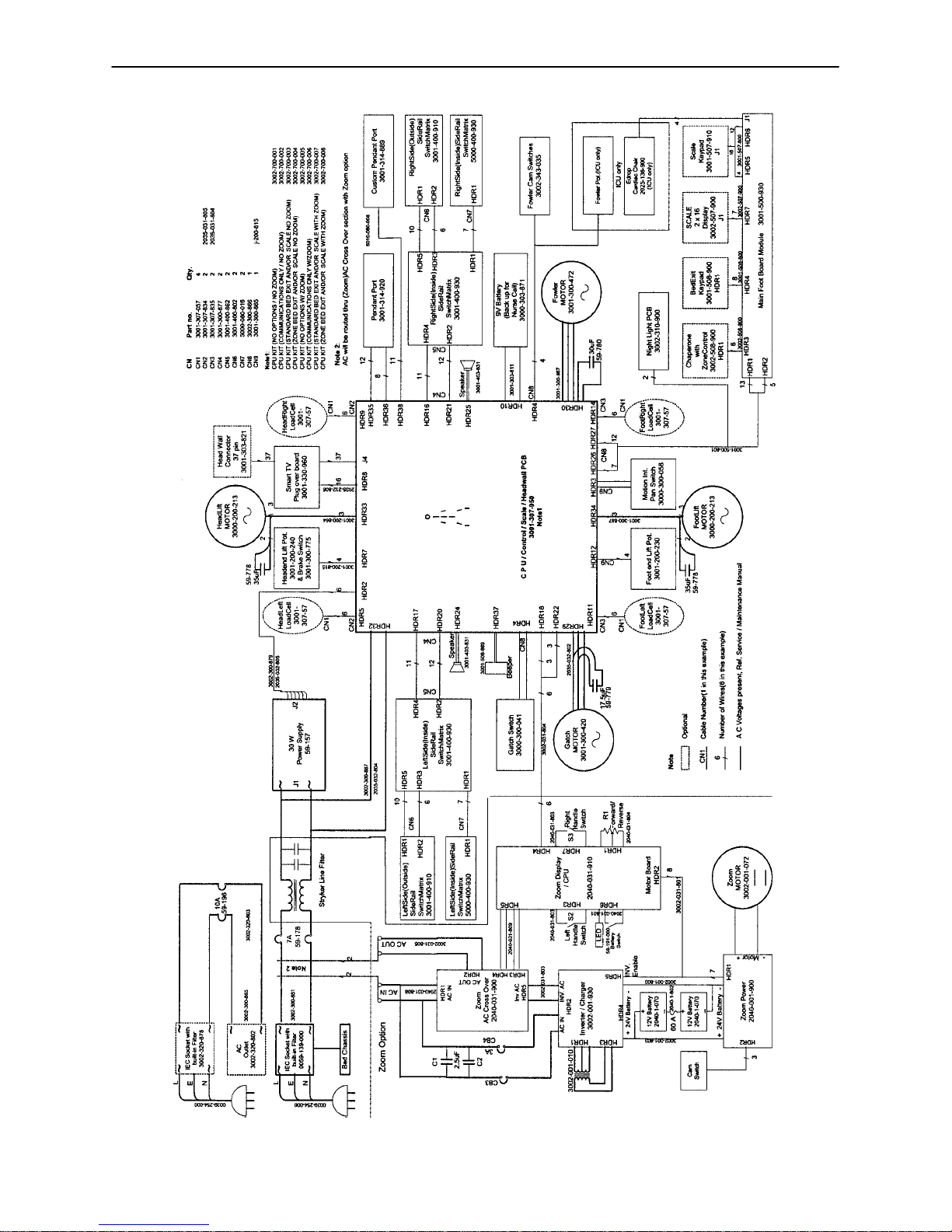
Bed Wiring Diagram
27
Page 29
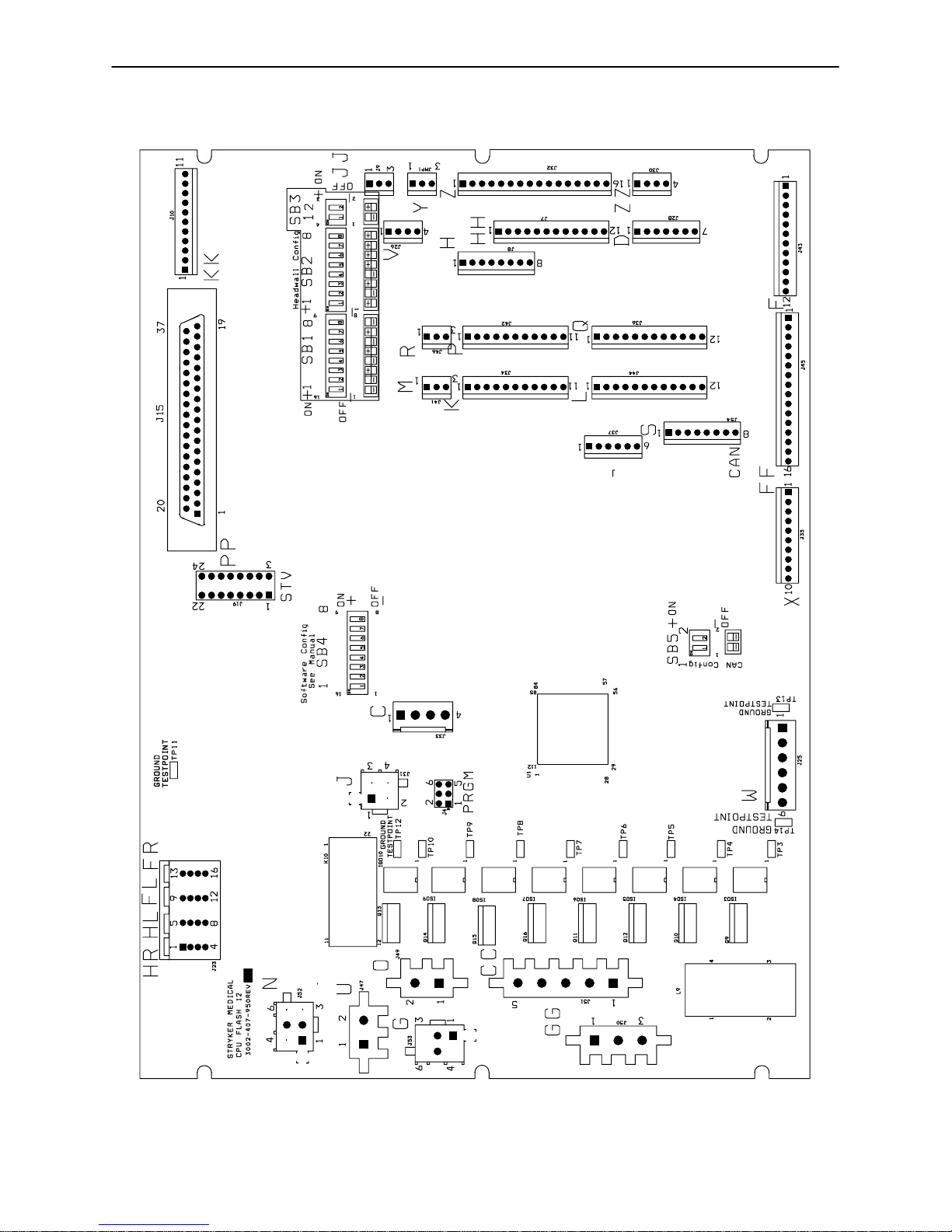
Electrical System Information
CPU BOARD − 3002−407−950
28
Page 30

Electrical System Information
CPU BOARD − 3002−407−950
CABLE
LOCATION
W +12 VDC Pin 1 Pin 4 or 5 Relays & Siderails Light
W +5 VDC Pin 2 & 3 Pin 4 or 5 +5 VDC from Power Sup-
W −12 VDC Pin 6 Pin 4 or 5 Relays & Siderails Light
ZZ +5 VDC Pin 1 Red Pin 4 Black +5 VDC for Fowler Pot
ZZ 0 − 5 VDC Pin 1 Red Pin 3 Green Fowler Pot Wiper
J 0 − 5 VDC Pin 3 Red Pin 2 White Head Lift Pot Wiper
J +5 VDC Pin 4 Green Pin 2 White +5 VDC for Head Lift Pot
C +5 VDC Pin 1 Pin 2 +5 VDC for Foot Lift Pot
C 0 − 5 VDC Pin 3 Pin 2 Foot Lift Pot Wiper
CC 0 VAC w/o Switch
CC 0 VAC w/o Switch
GG 0 VAC w/o Switch
GG 0 VAC w/o Switch
O 120 VAC Pin 1 Pin 2 Line Voltage to Bed
N 0 VAC w/o Switch
N 0 VAC w/o Switch
G 0 VAC w/o Switch
G 0 VAC w/o Switch
VOLTAGE POSITIVE
Pin 3 White Pin 1 Black Gatch Up
120 VAC w/Switch
Pin 3 White Pin 2 Red Gatch Down
120 VAC w/Switch
Pin 2 Black Pin 1 White Fowler Up
120 VAC w/Switch
Pin 3 Red Pin 1 White Fowler Down
120 VAC w/Switch
Pin 3 Black Pin 1 White Head Lift Down
120 VAC w/Switch
Pin 6 Red Pin 1 White Head Lift Up
120 VAC w/Switch
Pin 3 Black Pin 1 White Foot Lift Down
120 VAC w/Switch
Pin 6 Red Pin 1 White Foot Lift Up
120 VAC w/Switch
LEAD
NEGATIVE
LEAD
DESCRIPTION
Voltage
ply
Voltage
29
Page 31

Electrical System Information
SOFTWARE CONFIGURATION
1. Locate switch bank 4, labeled SB4 on the CPU board (see above).
2. Move the switches to the appropriate positions for the specific bed (see page 31 & 32).
3. To verify the switch settings, check what the foot board LCD displays in the burn−in mode. For beds with
a scale system, select software config. in the diagnostic mode.
30
Page 32

Electrical System Information
SOFTWARE CONFIGURATION (CONTINUED)
FUNCTIONAL TEST
ICU−KCI
MED−SURG−KCI
ICU−STANDARD BED
ICU−ZOOM / STANDARD BED
ICU−ZOOM / SCALE / BEDEXIT
ICU−ZOOM / SCALE / ZONE CONTROL BEDEXIT
ICU−SCALE / BEDEXIT
ICU−SCALE / ZONE CONTROL BEDEXIT
MED−SURG−STANDARD BED
MED−SURG−ZOOM / STANDARD BED
MED−SURG−ZOOM / SCALE / BEDEXIT
31
Page 33

Electrical System Information
T
SOFTWARE CONFIGURATION (CONTINUED)
MED−SURG−ZOOM / SCALE / ZONE CONTROL BEDEXIT
MED−SURG−SCALE / BEDEXIT
MED−SURG−SCALE / ZONE CONTROL BEDEXIT
MED−SURG−SHORT / ZOOM / STANDARD BED
MED−SURG−SHORT / ZOOM / SCALE / BEDEXIT
MED−SURG−SHORT / ZOOM / SCALE / ZONE CONTROL BEDEXI
MATERNITY
32
Page 34

Electrical System Information
POWER SUPPLY − P/N 59−157
CONNECTOR
LOCATION
J1 110V Pin 1 Pin 2
J2 12V Pin 1 Pin 4 or 5
J2 5V Pin 2 Pin 4 or 5
J2 5V Pin 3 Pin 4 or 5
J2 GND Pin 4 Pin 4 or 5
J2 GND Pin 5 Pin 4 or 5
J2 −12V Pin 6 Pin 4 or 5
VOLTAGE POSITIVE LEAD NEGATIVE LEAD
33
Page 35

Electrical System Information
INVERTER/CHARGER BOARD − PART NUMBER 3002−1−30
CONNECTOR
LOCATION
HDR 4 26 VDC Pin 2 Red Pin 1 Black From Battery − unplugged
HDR 1 22 VAC Pin 3 Red Pin 2 Secondarys from
HDR 1 34 VAC Pin 1 Green Pin 2 Brown Secondarys from
HDR 2 110 −140 VAC Pin 4 Brown Inverter Module
HDR 2 110 V Pin 2 Brown Pin 1 Blue From Wall − plugged in
HDR 3 120 V Pin 2 Plug−In Pin 1 Wall Voltage − plugged in
VOLTAGE POSITIVE
LEAD
NEGATIVE
LEAD
Pin 3 Blue
DESCRIPTION
Transformer − plugged in
Transformer − plugged in
Unplugged
34
Page 36

Electrical System Information
DISPLAY/CPU − P/N 2040−31−910
CONNECTOR
LOCATION
HDR 1 (H) 0−5VDC Pin 1 Pin 2 Control Pot Wiper Voltage
HDR 6 (J) Battery voltage around 26VDC Pin 1 Pin 5 Battery Voltage Return
HDR 4 (L) 5VDC Pin 9 Pin 1 Voltage from CPU
HDR 1 5VDC Pin 1 Pin 3 DC Voltage to Pot
HDR 7 Continuity Pin 1 Pin 4 Right Hand Switch
HDR 3 Continuity Pin 1 Pin 4 Left Hand Switch
HDR 2 26VDC Pin 3 Pin 1 Battery Voltage
VOLTAGE POSITIVE
LEAD
NEGATIVE
LEAD
DESCRIPTION
(with Switch On)
from On/Off Switch
(with Switch On)
35
Page 37

Electrical System Information
AC CROSSOVER BOARD − P/N 2040−31−900
CONNECTOR
LOCATION
HDR 5 (A) 120VAC Pin 4 Pin 1 AC Input to Board from
HDR 1 (C) 120VAC Pin 3 Pin 1 AC Input to Board from
HDR 2 (B) 120VAC Pin 2 Pin 1 AC Output of Board to
HDR 4 (E) +5VDC Pin 4 Pin 1 +5VDC when AC is
VOLTAGE POSITIVE LEAD NEGATIVE
LEAD
DESCRIPTION
the Inverter with the
Power Cord Unplugged
the Wall Receptacle
Main Power
Unplugged from the
Wall Receptacle
36
Page 38

Electrical System Information
DC MOTOR POWER BOARD − P/N 2040−1−900
CONNECTOR
LOCATION
HDR 1 (P) Battery voltage around 26VDC Pin 3 Red Pin 1 Black Battery Voltage out to the
HDR 2 (Q) 5VDC Disengaged
HDR 2 (Q) 5VDC Disengaged
VOLTAGE POSITIVE
LEAD
Pin 1 Red Pin 3 Black Drive Wheel
0VDC Engaged
Pin 2 Red Pin 3 Black Brakes
0VDC Engaged
NEGATIVE
LEAD
DESCRIPTION
Display/CPU Board
37
Page 39

Electrical System Information
INVERTER PROTECTION FEATURES
The inverter has several features to prevent internal damage:
1. Low Battery Voltage − If the battery voltage at the inverter drops below the low voltage cut−off, the inverter
will shut off.
2. Over−Temperature − If the inverter gets too hot, it will shut off. The overheating may be caused by high
ambient temperature, blocked air flow or an overload condition. When the inverter reaches an acceptable
temperature, it will restart.
3. Over−Power − The inverter will source up to its maximum power rating. If the load requires more, the
output voltage will shut down. Turning the power switch off and on will reset the inverter. Plugging the
bed power cord into the wall socket to charge the battery will reset the inverter.
WARNING
The inverter generates 115VAC, the same as a wall receptacle. To prevent injury, do not put anything into
the electrical outlets other than an appliance power cord. Keep the outlets covered when not in use. Do not
submerge the unit or subject it to moisture.
38
Page 40

3002−45−700 Optional Bed Communications Tester
Item Part No. Part Name Qty.
A 3002−45−805 BCT Unit 1
B 3001−303−825 37−Pin Cable 1
C 3002−45−806 Instructions 1
D 3000−303−871 9V Battery 1
39
Page 41

Headwall Output Configuration
37−PIN CONNECTOR
Pin 1 Option 2 Common
Pin 2 Read Light
Pin 3 Room Light
Pin 4 Speaker High
Pin 5 Pot Wiper
Pin 6 Radio Common
Pin 7 Nurse Call Interlock
Pin 8 Audio Transfer −
Pin 9 Audio Transfer +
Pin 10 Interlock +
Pin 11 Interlock −
Pin 12 Spare
Pin 13 Options 3 Common
Pin 14 Pot Low Common
Pin 15 Pot High Common (Std.)/Audio (STV)
Pin 16 Nurse Answer Light +
Pin 17 Option 1 NO/NC
Pin 18 Option 1 Common
Pin 19 Nurse Call Light +
Pin 20 Option 2 NO/NC
Pin 21 Option 3 NO/NC
Pin 22 Option 3A NO/NC
Pin 23 Option 2A Common
Pin 24 Option 2A NO/NC
Pin 25 Nurse Call +
Pin 26 Nurse Call NO/NC
Pin 27 Room/Read Light Common
Pin 28 Nurse Call Light −
Pin 29 Nurse Answer Light −
Pin 30 Priority NO/NC
Pin 31 Priority Common
Pin 32 Option 3A Common
Pin 33 TV − (Std.)/Data (STV)
Pin 34 TV + (Std.)/Common (STV)
Pin 35 Speaker Low Common
Pin 36 Audio Shield
Pin 37 Radio NO/NC
STRYKER PENDANT PORT
1 Scan Line
2 Audio (−)
3 Nurse Call (+)
4 +5 VDC
5 Scan Line
6 Scan Line
7 Nurse Call (−)
8 TV Channel Up
9 Backlight
10 Audio (+)
11 Gatch Up/Fowler In/Foot Up/DMS Firm
12 Gatch Down/Fowler Out/Foot Out/DMS
Soft
13 Fowler Up/Trend In
14 Fowler Down/Trend Out
15 Audio Shield
16 Not Used − Socket Filled
17 Litter Up
18 Ground
19 Read Light/Litter Down
20 Room Light
40
Page 42

Quick Reference Replacement Parts List
ELECTRICAL COMPONENTS
AC CROSSOVER BOARD 2040−31−900
FOOT BOARD KEYBOARD (S/R LIGHTS, LOCKOUTS, ETC.) 3001−500−930
FOOT BOARD SCALE DISPLAY 3001−507−900
FOOT BOARD SCALE KEYBOARD 3001−507−910
FOOT BOARD BED EXIT KEYBOARD 3001−508−900
CPU KIT 3002−407−950
DISPLAY/CPU BOARD 2040−31−910
INVERTER/CHARGER BOARD 3002−1−30
POWER BOARD 2040−1−900
POWER SUPPLY 59−157
SIDERAIL BOARDS
INSIDE BOARD 3001−400−930
OUTSIDE BOARD 3001−400−910
SPEAKER W/CABLE 3000−403−831
OTHER COMPONENTS
ADHESIVE, HEAD & FOOT BOARD “C” BUMPERS 72−2−71
BATTERY KIT 2040−700−13
CAPACITOR, FOWLER & GATCH 59−779
CAPACITOR, FOWLER & GATCH, 230V 59−153
CAPACITOR, LIFT 59−778
CAPACITOR, LIFT, 230V 3221−200−243
CASTER, 6” 3001−200−60
CASTER, STEER, 6” 3001−200−50
COIL CORD, LIFT POWER 3001−200−864
COIL CORD, LIFT SENSOR 3001−200−815
COMMUNICATIONS TESTER 3001−303−165
FOOT PROP RETROFIT KIT 2030−700−16
GREASE, SINGLE TUBE 3000−200−700
LOAD CELL 3002−307−57
41
Page 43

Quick Reference Replacement Parts List
OTHER COMPONENTS (CONTINUED)
MOTOR COUPLER KIT, LIFT 3000−200−725
MOTOR, DRIVE WHEEL 3002−1−72
MOTOR, FOWLER & GATCH W/CLUTCH 3001−300−560
MOTOR, FOWLER & GATCH W/CLUTCH, 230V 3221−300−705
MOTOR, LIFT (SAME FOR HEAD AND FOOT END) 3000−200−213
MOTOR, LIFT, 230V (SAME FOR HEAD AND FOOT END) 3221−200−213
PAINT, TOUCH−UP, OPAL, BOTTLE W/BRUSH 7000−1−321
PAINT, TOUCH−UP, OPAL, SPRAY CAN 7000−1−318
POTENTIOMETER, CONTROL BAR 2040−31−804
POTENTIOMETER, FOOT END 3001−200−230
POTENTIOMETER, FOWLER 2035−32−803
POTENTIOMETER, HEAD END 3001−200−240
POWER CORD 39−254
RESTRAINT STRAP, 2−PIECE 390−19
SIDERAIL COVER, RIGHT 3000−336−11
SIDERAIL COVER, LEFT 3000−336−12
SIDERAIL COVERS (SET OF FOUR) 2040−130
42
Page 44

Service Information
BRAKE PEDAL REPLACEMENT
Required Tools:
5/16” Hex Allen Wrench Torque Wrench Loctite 242
Hammer Punch #2 Phillips Screwdriver
Bungee Cords (or Equivalent)
Procedure:
1. Raise the litter to the full up position.
2. Unplug the power cord from the wall socket and push the battery power on/off switch to the “OFF” position.
3. Using a #2 Phillips screwdriver, remove the four screws holding the base hood to the frame. If necessary,
hold the covers out of the way by using bungee cords (or the equivalent) to secure them to the litter top.
4. Using a 5/16” hex Allen wrench, remove the two bolts holding the brake pedal to the brake rod.
5. Using a hammer and punch, remove the roll pins holding the brake shaft crank to the brake rod on both
the head and the foot end.
6. Push the brake rod through the frame until the brake pedal is clear. Remove the brake pedal.
7. Reverse steps 1 − 6 to attach the new brake pedal.
NOTE
Use Loctite 242 when reinstalling the bolts and torque the bolts to 25 foot−pounds.
43
Page 45

Service Information
LIFT MOTOR AND CAPACITOR REMOVAL AND REPLACEMENT
Required Tools:
3/8” Socket Wrench w/Extension 5/16” Socket Wrench Floor Jack
Side Cutters 7/16” Open End Wrench 2 x 4 (or Equivalent)
C
D
B
A
FOOT END
Procedure:
NOTE
If you need more space to work under the base frame, place a 2 x 4 across the base frame rails and use a
floor jack to raise the base frame off the floor.
1. Unplug the power cord from the wall socket and push the battery power on/off switch to the “OFF” position.
2. Using a 5/16” socket wrench, remove the five bolts holding the lower lift cover to the base and remove
the cover.
3. Disconnect the two connectors (A) at the motor capacitor.
4. Disconnect the white connector (B) from the power cord.
5. Using side cutters, cut the cable ties holding the capacitor (C) to the base and remove the capacitor.
6. Using a 3/8” socket wrench, remove the four screws (D) holding the motor assembly in the lift housing
and remove the motor assembly.
7. Reverse steps 1 − 6 to install the new motor.
NOTE
The drive shaft on the new motor might need to be turned with a 7/16” open end wrench to align with the coupler.
The procedure for lift motor and capacitor removal and replacement is the same for both ends of the bed.
44
Page 46

Service Information
LIFT HOUSING REMOVAL AND REPLACEMENT
Required Tools:
#2 Phillips Screwdriver Bungee Cord (or Equivalent) 5/16” Socket Wrench
Side Cutters 9/16” Socket Wrench Floor Jack
7/32” Hex Allen Socket Wrench Sawhorses (or Equivalent) 2 x 4 (or Equivalent)
3/8” Socket Wrench (w/ 6” extension)
Procedure:
NOTE
If you need more space to work under the base frame, place a 2 x 4 across the base frame rails and use a
floor jack to raise the base frame off the floor.
1. Unplug the power cord from the wall socket and push the battery power on/off switch to the “OFF” position.
2. Using a 5/16” socket wrench, remove the five bolts holding the lower lift cover to the base and remove
the cover.
3. Using a #2 Phillips screwdriver, remove the three screws holding the upper lift cover to the base. If necessary, hold the upper and lower covers out of the way by using bungee cords (or the equivalent) to secure
them to the litter top.
4. Remove the lift motor and capacitor (refer to the procedure on page 44).
5. Remove the lift potentiometer (refer to the procedure on page 47).
6. Using a 5/16” socket wrench, remove the cable clamps holding the power and sensor coil cords on top
of the lift housing assembly. Cut the cable ties and disconnect the coil cords from under the lift housing.
The power and sensor coil cords are now free of the lift housing assembly. Drape them up out of the way.
7. Using a 7/32” hex Allen socket, remove the two screws holding the lift screws to the header crossbar
plate.
8. Lift the litter top up and support it about 6” above the lift screws on sawhorses or the equivalent.
45
Page 47

Service Information
LIFT HOUSING REMOVAL AND REPLACEMENT (CONTINUED)
A
FOOT END − BOTTOM VIEW
9. Under the base, using a 9/16” socket, remove the four nuts (A) holding the lift housing to the base.
10. Lift up and out on the lift housing assembly to remove it from the base.
CAUTION
To ensure proper reattachment of the power and sensor coil cords, refer to the procedure on page 50. Refer
to the procedure on page 47 for reattachment of the lift potentiometer.
11. Reverse steps 1 − 10 to reinstall the lift housing assembly after service is completed.
NOTE
The procedure for lift housing removal and replacement is the same for both ends of the bed.
46
Page 48

Service Information
LIFT POTENTIOMETER REPLACEMENT AND ADJUSTMENT
Required Tools:
#2 Phillips Screwdriver Bungee Cord (or equivalent) 5/16” Socket Wrench
3/8” Open End Wrench Side Cutters
C
B
B
A
Procedure:
1. Raise the litter to the full up position.
2. Unplug the power cord from the wall socket and push the battery power on/off switch to the “OFF” position.
3. Using a 5/16” socket wrench, remove the five bolts holding the lower lift cover to the base and remove
the cover. If necessary, hold the covers out of the way by using bungee cords (or the equivalent) to secure them to the litter top.
4. Using a #2 Phillips screwdriver, remove the three screws holding the upper lift cover to the base. If necessary, hold the covers out of the way by using bungee cords (or the equivalent) to secure them to the litter.
5. Using side cutters, cut the cable tie (A) holding the pot cable to the coil cord.
6. Unplug the pot cable from the sensor coil cord. If replacing a pot at the head end of the bed, unplug the
cables attached to the brake sensor switch.
7. Pull the pot cable up through the base.
8. Using a 3/8” open end wrench, remove the two bolts (B) holding the pot housing (C) to the lift housing.
47
Page 49

Service Information
LIFT POTENTIOMETER REPLACEMENT AND ADJUSTMENT (CONTINUED)
9. Lift up and out on the pot housing assembly to remove it from the lift housing.
10. Before installing the new pot on the bed, turn it clockwise until it stops. Turn it back counterclockwise
two full (360) revolutions. This allows a ”window” position for proper upper and lower limits.
11. Reverse steps 4−9 to install the new pot and pot housing assembly.
12. After installing the new pot, the “burn−in” procedure below must be followed.
NOTE
Be sure to maintain the pot position while installing.
LIFT POTENTIOMETER “BURN−IN” PROCEDURE
NOTE
It requires two people to enable the diagnostics mode for the bed.
1. Unplug the bed power cord from the wall socket.
2. On the foot board control panel, hold down the bed motion lock button and the button to lock out the siderail controls for the knee. While still holding the buttons, plug the bed power cord into the wall socket.
Release the foot board buttons. The siderail control lights LED should be flashing to indicate the bed is
in diagnostics mode.
3. To “burn in” the Bed Up/Down limits, raise the bed completely up until it can’t go any farther. Press and
hold the “Bed Motion Lock” button. The “Bed Motion Lock” LED will light. Continue to hold the “Bed Motion Lock” button until the“Bed Motion Lock” LED flashes. The flashing LED indicates the limits have been
set. Release the“Bed Motion Lock” button and unplug the power cord from the wall socket to complete
the “burn in” mode.
4. Plug the power cord into the wall socket and verify the lift limits are set properly before returning the bed
to service.
5. If your bed has an IV Caddy, a lower limit must be burned in. Run the litter down to 19.5 inches. Hold
the Bed Up/Down Lock button until the light flashes.
CAUTION
Do not run the litter all the way down while in the diagnostics mode. Damage to the botton lift covers could
result.
48
Page 50

Service Information
LIFT MOTOR COUPLER REPLACEMENT
Required Tools:
5/16” Socket Wrench 3/8” Socket Wrench (w/6” Extension) Floor Jack
2 x 4 (or Equivalent)
C
B
A
A
Procedure:
NOTE
If you need more space to work under the base frame, place a 2 x 4 across the base frame rails and use a
floor jack to raise the base frame off the floor.
1. Unplug the power cord from the wall socket and push the battery power on/off switch to the “OFF” position.
2. Using a 5/16” socket wrench, remove the five bolts holding the lower lift cover to the base and remove
the cover.
3. Using a 3/8” socket with an extension, remove the four bolts (A) holding the isolation plate (B) to the lift
housing and lower the lift motor and isolation plate assembly to allow access to the coupler (C).
4. The motor coupler can now be removed from the lift housing.
5. Reverse steps 1 − 4 to install the new motor coupler and bushings.
49
Page 51

Service Information
POWER AND SENSOR COIL CORD REPLACEMENT
Required Tools:
#2 Phillips Screwdriver Side Cutters 5/16” Socket Wrench
Bungee Cord (or equivalent) 5/16” Nut Driver Floor Jack
2 x 4 (or Equivalent)
Procedure:
NOTE
If you need more space to work under the base frame, place a 2 x 4 across the base frame rails and use a
floor jack to raise the base frame off the floor.
1. Unplug the power cord from the wall socket and push the battery power on/off switch to the “OFF” position.
2. Using a 5/16” socket wrench, remove the five bolts holding the lower lift cover to the base and remove
the cover.
3. Using a #2 Phillips screwdriver, remove the three screws holding the upper lift cover to the base. If necessary, hold the covers out of the way by using bungee cords (or the equivalent) to secure them to the litter
top.
4. Using side cutters, cut the cable ties holding the power and sensor coil cords to the base. Remove the
ground wire coming from the sensor cord that is attached to the base (note the star washer arrangement).
5. Disconnect the cables going to the motor and the lift potentiometer (at the head end, the sensor cord is
also attached to the brake switch sensor).
6. Pull both cords up through the frame of the bed and the lift housing.
7. Using a 5/16” socket wrench, remove the two screws (A) holding the cable clamps* to the top of the lift
housing.
8. Using a 5/16” socket wrench, remove the two screws (B) securing the cable clamps* to the underside
of the header crossbar assembly.
9. Pull both coil cords up through the header crossbar assembly.
10. Disconnect the power and sensor coil cords from the connectors.
11. The cords should now be completely removed from the bed. Reverse the above steps to install the new
power and sensor cords.*
CAUTION
* When the power and sensor coil cords are being replaced, secure the cable clamps to the cords at the first
coil both on the top and on the bottom to ensure there is not too much slack in the cords between the top of
the lift housing assembly and the bottom of the header crossbar. Be sure the clamps are fastened at exactly
the correct angle, as shown by the arrows in the illustration on page 51. Arrange the cords exactly as shown
in the illustration (left in front of right). If this is not done correctly, damage to the cords will result.
50
Page 52

Service Information
B
B
A
A
VIEW FROM CENTER OF BED
51
Page 53

Service Information
BATTERY REMOVAL AND REPLACEMENT
Required Tools:
Torx T27 7/16” Wrench
1/2” Socket Wrench Bungee Cords
Phillips Screwdriver
5/32” Allen Wrench
Procedure:
1. Raise the litter to full up. Unplug the
power cord from the wall socket and
push the battery power on/off switch to
the “OFF” position.
2. Using a Phillips screwdriver, remove the
four screws holding the base hood to the
base frame.
3. Lift the base hood and support it from
the litter frame using bungee cords or
the equivalent.
4. Properly ground yourself (see page 20
for static discharge precautions).
5. Open the cable clamp at the head end,
left side of the base frame and remove
the cables from the clamp.
6. Using a Torx T27, remove the four
screws (A) holding the electronics box
cover and remove the cover.
7. Disconnect the two battery cables (B).
WARNING
The battery tray assembly weighs 50
pounds. Use caution when removing the
two hex head screws securing it to the base
frame or personal injury could result.
Battery posts, terminals and related accessories contain lead and lead compounds,
chemicals known to the State of California to
cause cancer and birth defects or other reproductive harm. Wash hands after han-
dling. Properly dispose of the old battery in
accordance with local regulations.
A
B
8. Support the battery tray assembly from
the bottom. Using a 7/16” hex socket or
wrench, remove the two screws (C) supporting the battery tray.
C
52
Page 54

Service Information
BATTERY REMOVAL AND REPLACEMENT (CONTINUED)
9. The back of the battery tray assembly has a lip which catches on the electronics box. Lift up and out to
remove the battery tray assembly.
10. Using a Phillips screwdriver, remove the two screws holding the battery terminal to the battery tray.
11. Using a 5/32” Allen wrench and a 7/16” wrench, remove the four screws and nuts holding the battery
harness to the battery terminals.
12. Reverse steps 1 − 11 to install the new batteries. Complete the last four items of the set−up procedures
on page 8.
DC MOTOR BOARD REMOVAL AND REPLACEMENT
Required Tools:
Phillips Screwdriver 1/8” Allen Wrench Bungee Cords
T27 Torx
Procedure:
1. Raise the litter to the full up position.
2. Unplug the power cord from the wall socket and push the battery power on/off switch to the “OFF” position.
3. Using a Phillips screwdriver, remove the four screws holding the base hood to the base frame.
4. Open the cable clamp at the head end, left side of the base frame and remove the cables from the clamp.
5. Lift the base hood and support it from the litter frame using bungee cords or the equivalent.
6. Using a T27 Torx, remove the four screws holding the cover to the side of the electronics box.
7. Properly ground yourself (see page 20 for static discharge precautions).
8. Using a 1/8” Allen wrench, remove the four bolts and standoffs holding the motor board to the electronics
box.
9. Remove all cables from the motor board and remove the board.
NOTE
Note the locations of the cables so you can connect them properly to the new motor board.
10. Reverse steps 1 − 8 to install the new motor board.
53
Page 55

Service Information
DRIVE MOTOR REMOVAL AND REPLACEMENT
Required Tools:
Phillips Screwdriver 1/2” Socket Wrench Bungee Cords
Floor Jack T27 Torx
Procedure:
1. Raise the litter to the full up position.
2. Unplug the power cord from the wall socket and push the battery power on/off switch to the “OFF” position.
3. Using a Phillips screwdriver, remove the four screws holding the base hood to the base frame.
4. Open the cable clamp at the head end, left side of the base frame and remove the cables from the clamp.
5. Lift the base hood and support it from the litter frame using bungee cords or the equivalent.
6. Using a T27 Torx, remove the four screws holding the power board cover to the side of the electronics
box. Remove the two motor wires from the power board and remove the T27 Torx ground screw.
7. Apply the brakes and disengage the drive wheel. Place a floor jack under the leaf spring at the foot end
of the bed and raise the wheels approximately three inches off the floor.
8. Using a 1/2” socket wrench, remove the four bolts holding the drive motor to the leaf spring.
CAUTION
Support the drive motor before removing the four bolts to prevent it from falling to the floor and becoming
damaged.
9. Reverse steps 1 − 8 to install the new drive motor.
10. Run through the operation of the power drive wheel to ensure it is operating properly before returning the
unit to service.
DRIVE WHEEL REMOVAL AND REPLACEMENT
Required Tools:
Phillips Screwdriver 1/2” Socket Wrench Bungee Cords
Floor Jack T27 Torx
Procedure:
1. Remove the drive motor (see procedure above).
2. Using a 1/2” socket wrench, remove the bolt holding the wheel to the drive motor.
3. Slide the wheel off the motor shaft.
4. Reverse steps 1 − 3 to install the new drive wheel and reinstall the drive motor.
54
Page 56

Service Information
SCALE SYSTEM DIAGNOSTICS AND CALIBRATION
Diagnostic Mode Functions:
1. ANGLE CALIBRATE − This may be required in the field to recalibrate the scale. Calibrate using 50
pounds.
2. DISP. CORNER LBS − This function displays the individual corner weights in pounds
and can be used to isolate a defective load cell.
3. DISP. CORNER CTS − This function displays the individual corner weights in counts for each load cell
and can be used to isolate a defective load cell.
4. DISPLAY FACTORS – This function is used to see the scale calibration factors. This can be used to
diagnose a bad scale calibration.
5. DISPLAY AVERAGES − This function is used to see the average weight in pounds each load cell has
experienced.
6. DISPLAY MAXIMUMS − This function is used to see the maximum weight each load cell has experi-
enced.
7. CLEAR STATISTICS − This function is used to clear the averages and maximums.
8. INIT TO DEFAULTS − This function is used to reset the scale factors back to defaults.
9. VIEW ERROR LOG − This function can be used to see a log of scale errors and the time they occurred.
10. LOCK/UNLOCK UNITS − This function can be used to lock out the ability to change weight units.
11. PICK EXIT ALARM − This function can be used to select a different bed exit alarm tone.
12. SOFTWARE CONFIG − This function can be used to see what the bed configuration is.
13. SOFTWARE VERSION − This function can be used to see what software version it is.
14. CALIBRATE SCALE − This is the old scale calibration routine with 200 pounds. Only there for backup
purposes.
for each load cell
15. EXIT DIAGNOSTIC − This function will give you the ability to exit the diagnostic mode and go into scale
mode.
Diagnostic Mode:
NOTE
It requires two people to enable the diagnostic mode for the scale system.
1. To enter diagnostic mode, unplug the bed’s power cord from the wall socket.
2. Press and hold down the LBS/KGS button.
3. While still holding the LBS/KGS button, plug the bed’s power cord into the wall socket.
4. After two seconds, release the LBS/KGS button. The LCD should display “ANGLE CALIBRATE”. The
diagnostic mode is now active.
Displaying Individual Load Cell Outputs:
A defective load cell can be detected by entering diagnostics and displaying individual load cell outputs.
1. Enter the diagnostic mode. The LCD will display “ANGLE CALIBRATE” when the diagnostic mode is activated.
2. Repeatedly press and release the up or down arrow button (ZERO or SCALE ON/OFF) until the LCD displays “DISPLAY CORNER CTS”.
3. Press and release the ENTER button (LBS/KGS). The LCD should display “ƜƝ SELECT CORNER”.
55
Page 57

Service Information
SCALE SYSTEM DIAGNOSTICS AND CALIBRATION (CONTINUED)
Displaying Individual Load Cell Outputs (Continued):
The two buttons listed below function as POSITION buttons to select the four corners of the bed’s litter.
Whenever the LCD displays “ƜƝ SELECT CORNER”, press one of these buttons to cycle through the
corners and to select the load cell assembly at the desired corner.
A. ZERO = cycle up through the four corners
B. SCALE ON/OFF = cycle down through the four corners
4. Press and release the position button that corresponds with the load cell to be checked. The LCD should
display “X/X=NNN.N”. ”X/X” represents the initials of the selected corner, i.e. H/R will be displayed for
the patient’s head end, right side. ”NNN.N” represents the resistance of the load cell.
5. Repeat step four for each corner. Head end weight readings will normally be lower than foot end weights.
Weight readings should be constant. A drifting 000.0 or 999.9 weight, or a reading that does not change
when weight is applied to that corner of the bed indicates a problem with the selected load cell assembly
or load cell cable.
Verifying Scale Accuracy:
1. Zero the empty bed. Place a known weight on the center of the bed; the heavier the better and no less
than 100 pounds. The displayed weight should be within ± 1% of the actual weight.
2. If the displayed weight is not accurate, remove the weight from the bed and proceed to the Scale Calibration
section.
Scale Calibration:
NOTE
It requires two people to enable the calibration mode for the scale system.
Raise the siderails when calibrating the scale to avoid getting inaccurate scale readings due to possible interference between the siderails and the casters.
Calibrate the scale system with a known 50 pound weight. If exactly 50 pounds is not available, the factory
default for calibration will have to be changed as described in step 6.
1. To enter the calibration mode, unplug the bed’s power cord from the wall socket.
2. Press and hold down the LBS/KGS button.
3. While still holding the LBS/KGS button, plug the bed’s power cord into the wall socket.
4. After two seconds, release the LBS/KGS button. The LCD should read “ANGLE CALIBRATE”. The cal-
ibration mode is now active.
5. Press and hold the ENTER button (LBS/KGS). Zero the bed, following the displayed instructions. When
the bed is zeroed, the LCD should display “REF X100=<0>5000”. This is the factory default for 50
pounds. If 50 pounds will be used to calibrate the scale, proceed to step 7.
56
Page 58

Service Information
SCALE SYSTEM DIAGNOSTICS AND CALIBRATION (CONTINUED)
Scale Calibration (Continued):
6. If exactly 50 pounds is not available, change the display to match the weight you are using. Pressing
the CHANGE EQUIP button will move the cursor position to the right. Pressing the up arrow (ZERO)
button will increase the numbers. Pressing the down arrow (SCALE ON/OFF) button will decrease the
numbers. Scroll through the numbers until they match the weight you will use for calibration.
7. Press and release the ENTER button and the LCD will display “PRESS REV. TREND”. Press and hold
the button with the Reverse Trendelenburg symbol (feet down/head up) until the bed stops. Release the
button and the LCD will display “DO NOT TOUCH BED”. Press and hold the Reverse Trendelenburg
button again until the bed stops. Release the button and the LCD will display “DO NOT TOUCH BED”.
8. The LCD will display “PRESS TREND.” Press and hold the button with the Trendelenburg symbol (feet
up/head down) until the bed stops. Release the button and the LCD will display “DO NOT TOUCH BED”.
Press and hold the Trend button again until the bed stops. Release the button and the LCD will display
“DO NOT TOUCH BED”.
9. Repeat steps 5 − 8 with 200 pounds.
10. The LCD will display the weight. This indicates the calibration procedure is complete.
11. Level the bed at a full up or full down position. Remove the weight and zero the bed.
12. Verify scale accuracy and functionality before returning the bed to service.
57
Page 59

Service Information
LOAD CELL REPLACEMENT
Required Tools:
9/16” Socket Wrench 9/16” Open End Wrench Saw Horse (or Equivalent)
Wire Cutters
Replacement Procedure:
1. Raise the Fowler or knee section, depending which end of the litter needs service.
2. Unplug the load cell connector from the load cell cable.
3. Using wire cutters, remove the wire ties holding the cable to the frame.
4. Using a 9/16” socket and a 9/16” open end wrench, remove the two bolts holding the load cell to the litter
cross tube and remove the load cell.
5. Using a saw horse or the equivalent, support the litter at the end where the load cell was removed. Reverse
the above procedure to install the new load cell.
NOTE
The scale calibration procedure must be performed after the load cell is replaced (see page 56).
HEAD MOTOR REMOVAL AND REPLACEMENT
Required Tools:
T27 Torx 7/16” Socket Wrench 3/8” Socket Wrench
Wire Cutters
Procedure:
1. Run the litter to the full up position and remove the mattress from the litter.
2. Fold the foot section back toward the head end. Electrically run the knee section to full up. If the knee
section will not move electrically, pull the foot section toward the head end while pulling the CPR release
handle (located at the head end of the bed). The knee section will raise.
3. Using a T27 torx, remove the four screws holding the cover to the actuator box and remove the cover.
4. Remove the two CPR release cables from the CPR release bracket. Using a 3/8” socket wrench under-
neath the actuator box, remove the two bolts holding the release bracket to the actuator box and remove
the bracket from the actuator box.
5. Disconnect all the electrical connections to the head motor and move aside any wiring that interferes with
the removal of the motor.
6. Using a 3/8” socket wrench underneath the actuator box, remove the four bolts holding the motor mount-
ing bracket to the actuator box. Lift up and out on the motor to remove it.
7. Remove the motor mounting bracket from the old motor and install it on the replacement motor.
8. Reverse steps 3 through 6 to install the replacement motor.
9. Verify the unit is working properly before returning it to service.
58
Page 60

Service Information
KNEE MOTOR REMOVAL AND REPLACEMENT
Required Tools:
T27 Torx 7/16” Socket Wrench 3/8” Socket Wrench
Wire Cutters
Procedure:
1. Run the litter to the full up position and remove the mattress from the litter.
2. Fold the foot section back toward the head end. Electrically run the knee section to full up. If the knee
section will not move electrically, pull the foot section toward the head end while pulling the CPR release
handle (located at the head end of the bed). The knee section will raise.
3. Using a 7/16’ socket wrench, remove the mounting bolt on the litter for the knee dampening cylinder. This
leaves the knee dampener mounted only to the seat panel.
4. Using a T27 torx, remove the four screws holding the cover to the actuator box and remove the cover.
5. Remove the two CPR release cables from the CPR release bracket. Using a 3/8” socket wrench under-
neath the actuator box, remove the two bolts holding the release bracket to the actuator box and remove
the bracket from the actuator box.
6. Disconnect all the electrical connections going to the knee motor and move aside any wiring that could
interfere with the removal of the motor.
7. Pull the foot panel toward the head end of the bed. This causes the knee motor linkage to roll past center
and allows the motor to be removed without supporting the knee section.
8. Using a 3/8” socket wrench underneath the actuator box, remove the four bolts holding the motor mount-
ing bracket to the actuator box. Lift up and out on the motor to remove it.
9. Remove the motor mounting bracket from the old motor and install it on the replacement motor.
10. Install the replacement motor.
11. Reverse steps 3 − 5 to reinstall the knee dampener, CPR bracket and actuator box cover.
12. Pull the foot panel toward the foot end of the bed. This causes the knee motor linkage to roll back past
center.
CAUTION
If step 12 is not done, damage to the motor or linkage will occur.
13. Verify the bed is working properly before returning it to service.
59
Page 61

Service Information
POWER SUPPLY REMOVAL AND REPLACEMENT
Required Tools:
T27 Torx Needle−Nose Pliers
Procedure:
1. Run the litter to the full up position and remove the mattress from the litter.
2. Fold the foot section back toward the head end of the bed. Electrically run the knee section to full up.
If the knee section will not move electrically, pull the foot section toward the head end of the bed while
pulling the CPR release handle (located at the head end of the bed). The knee section will raise.
3. Using a T27 torx, remove the four screws holding the cover to the actuator box and remove the cover.
4. Properly ground yourself (see page 20 for static discharge precautions).
5. Unplug all electrical connections from the power supply.
6. Using needle−nose pliers, squeeze the four stand−offs supporting the power supply and pull up gently
on the power supply to remove it.
7. Reverse steps 2 through 5 to install the new power supply.
8. Verify the unit is working properly before returning it to service.
CPU BOARD REMOVAL AND REPLACEMENT
Required Tools:
T27 Torx Needle−Nose Pliers
Replacement Procedure:
1. Run the litter to the full up position and remove the mattress from the litter.
2. Fold the foot section back toward the head end of the bed. Electrically run the knee section to full up.
If the knee section will not move electrically, pull the foot section toward the head end of the bed while
pulling the CPR release handle (located at the head end of the bed). The knee section will raise.
3. Using a T27 torx, remove the four screws holding the cover to the actuator box and remove the cover.
4. Properly ground yourself (see page 20 for static discharge precautions).
5. Unplug all electrical connections from the CPU board.
6. Press the six stand−offs away from the board while gently lifting the board up and out.
7. Install the replacement CPU board.
NOTE
After the replacement CPU board is installed, the “burn−in” procedure must be performed for the Fowler and
lift motor potentiometers (see page 48 and page 62)
If the bed is equipped with a scale system, the scale calibration procedure must also be performed after the
replacement CPU board is installed (see page 56).
60
Page 62

Service Information
FOWLER POTENTIOMETER REPLACEMENT
Required Tools:
T27 Torx Wire Cutters 1/2” Open End Wrench
7/64” Allen Wrench
Replacement Procedure:
1. Manually crank the knee section up until it stops.
2. Using a T27 Torx, remove the four screws holding the litter access cover to the litter and remove the cover.
3. Using a 7/64” Allen wrench, loosen the screw holding the linkage to the pot. shaft and remove the linkage
from the shaft.
4. Using a 1/2” open end wrench, remove the nut holding the potentiometer to the frame.
5. Using wire cutters, remove the cable ties from the cable. Unplug the cable from the CPU and remove the
pot.
6. Reverse the above procedure to install the replacement potentiometer.
7. The new potentiometer must be calibrated after it has been installed.
8. The Fowler pot. should be set at 150 ohms ($ 10 ohms) in the full down position. This reading must be
taken from pins 3 and 4 on the connector with the pot. unplugged from the board. After the correct ohm
reading is achieved, tighten the screw on the linkage.
9. Perform the “burn−in” procedure for the Fowler potentiometer (see page 62).
61
Page 63

Service Information
FOWLER POTENTIOMETER “BURN−IN” PROCEDURE
NOTE
It requires two people to enable the diagnostics mode for the bed.
1. Unplug the bed power cord from the wall socket.
2. On the foot board control panel, hold down the bed motion lock button and the button to lock out the siderail controls for the knee. While still holding the buttons, plug the bed power cord into the wall socket.
Release the foot board buttons. The siderail control lights LED should be flashing to indicate the bed is
in diagnostics mode.
3. Using the foot board controls, run the Fowler up to 90. Press and hold the button on the foot board to
lock out the siderail controls for the back until the padlock LED flashes. Release the button.
4. Using the foot board controls, run the Fowler down to 0. Press and hold the button on the foot board
to lock out the siderail controls for the knee until the padlock LED flashes. Release the button..
62
Page 64

Service Information
AC CROSSOVER BOARD REPLACEMENT
Required Tools:
T27 Torx 1/2” Box End Wrench #2 Phillips Screwdriver
Wire Cutters Small Flat Blade Screwdriver Needle Nose Pliers
5/16” Nut Driver
Replacement Procedure:
1. Follow steps 1 − 9 of the control bar potentiometer replacement procedure on page 65.
2. Using a T−27 Torx, remove the 2 bolts holding the AC crossover board cover to the head end frame and
remove the cover.
3. Disconnect all wires from the AC crossover board.
4. Using needle nose pliers, release the four mounting stand−offs from the board and remove the board.
5. Reverse steps 1 − 4 to install the new board.
6. Reverse steps 1 − 9 of the control bar potentiometer replacement procedure on page 65 to reassemble
the bed.
DISPLAY/CPU BOARD REPLACEMENT
Required Tools:
T27 Torx 1/2” Box End Wrench #2 Phillips Screwdriver
Wire Cutters Small Flat Blade Screwdriver Needle Nose Pliers
5/16” Nut Driver
Replacement Procedure:
1. Follow steps 1 − 9 of the control bar potentiometer replacement procedure on page 65.
2. Disconnect all wires from the display/CPU board.
3. Using a #2 Phillips screwdriver, remove the six screws holding the display/CPU board to the control bar
cover and remove the board.
4. Reverse steps 2 & 3 to install the new board. After the new board has been installed, the potentiometer
“burn−in” procedure must be performed (see page 66).
5. Reverse steps 1 − 9 of the control bar potentiometer replacement procedure on page 65 to reassemble
the bed.
63
Page 65

Service Information
CONTROL BAR POTENTIOMETER REPLACEMENT
Required Tools:
T27 Torx 1/2” Box End Wrench #2 Phillips Screwdriver
Wire Cutters Small Flat Blade Screwdriver 5/16” Nut Driver
Replacement Procedure:
1. Raise the litter and the head end to the full up position.
2. Remove the head board from the bed.
3. Unplug the power cord from the wall socket and push the battery power on/off switch to the “OFF” position.
4. Using a 5/16” nut driver, remove the screw (A) holding the power cord clamp to the bumper weldment
and remove the clamp from the bumper.
FIGURE 1
A
64
Page 66

Service Information
CONTROL BAR POTENTIOMETER REPLACEMENT (CONTINUED)
5. Using a T27 Torx, remove the four bolts (C) at the head end of the bed holding the control bar mounting
bracket to the head end (see Figure 2).
6. Using a #2 Phillips screwdriver, remove the three screws (D) holding the control bar cover to the head
end of the bed (see Figure 3).
7. Standing at the head end, pull the control bar toward you and fold down the control bar mounting bracket.
8. Using a 1/2” wrench, remove the nut holding the potentiometer to the mount. Using wire cutters, cut the
wire ties. Unplug the pot cable from the CPU display board and remove the pot.
9. Install the new potentiometer. Using a small flat blade screwdriver, turn the pot shaft clockwise until it
stops. Turn it back counterclockwise 1/2 turn.
10. After the new pot has been installed, the potentiometer “burn−in” procedure must be performed (see
page 66).
11. After performing the “burn−in” procedure, reverse steps 1 − 9 to reassemble the bed.
12. Test all functions before returning the unit to service.
C
FIGURE 2
D
D D
FIGURE 3
65
Page 67

Service Information
CONTROL BAR POTENTIOMETER “BURN−IN” PROCEDURE
Required Tools:
T27 Torx 1/2” Box End Wrench #2 Phillips Screwdriver
Wire Cutters Small Flat Blade Screwdriver 5/16” Nut Driver
1. If it has not already been done, follow steps 1 − 9 of the control bar potentiometer replacement procedure
on page 65.
2. Hold down the switch on the back of the drive CPU board.
3. With the switch depressed, move the battery power on/off switch to the “ON” position.
4. Verify the “ENGAGE DRIVE WHEEL” LED at the head end of the bed is flashing.
5. Move the battery power on/off switch to the “OFF” position, close the drive control box, and move the
switch back to the “ON” position.
6. The “ENGAGE DRIVE WHEEL” LED will flash once. The control bar potentiometer is calibrated.
7. Grasp the drive handle and squeeze the motion release switch without moving the drive handle forward
or back. Verify the bed does not move.
8. Release the bed brakes and engage the drive wheel. Standing at the head end of the bed, grasp the drive
handle and squeeze the motion release switch while moving the drive handle away from you. Verify the
bed moves forward.
9. Grasp the drive handle and squeeze the motion release switch while moving the drive handle toward you.
Verify the bed moves backward.
10. Reverse steps 1 − 9 of the control bar potentiometer replacement procedure on page 65 to reassemble
the bed.
66
Page 68

Service Information
OPTIONAL SMART TV INTERFACE “BURN−IN” PROCEDURE
This procedure is used for selecting the style of TV interface desired for your bed. If traditional TV is desired,
no calibration is required. If optional Smart TV is available on the bed, select one of the TV manufacturers
listed in the table below.
SET−UP
Ensure the communication cable is connected between the bed and the Db37 wall port or the pillow
speaker port of the nurse call system. If available, a bed communication tester can be used instead of
the hospital wiring.
PROCEDURE
1. Place the bed in the lift potentiometer burn−in mode (see page 48).
2. Notice the Nurse Call LED (yellow) is flashing. Notice the Nurse Answer LED (green) is flashing on/off
slowly.
3. Press and release the TV ON/OFF switch on the bed’s siderail once. Notice the Nurse Call LED flashes
once. This is the first selection of TV manufacturers for the Smart TV mode. Notice the Nurse Answer
LED (green) is flashing on/off slowly. The Nurse Answer LED will only light when the Nurse Call LED
(yellow) is flashing.
4. Press and release the TV ON/OFF switch on the bed’s siderail to scroll to other TV manufacturers. Notice
the number of times the Nurse Call LED flashes matches the number listed in the table below and represents the TV manufacturer selected.
5. When the desired TV manufacturer has been selected, unplug the bed power cord from the wall socket
and plug it back in to complete the Smart TV burn−in procedure.
NOTE
If the bed is connected to a television during the burn−in procedure, the television will turn on when the correct
setting is selected.
TV MANUFACTURER SELECTION FOR SMART TV BURN−IN PROCEDURE
Press and release TV ON/OFF switch: Nurse Call LED (Yellow) TV Manufacturer
One time One flash RCA 1
Two times Two flashes RCA 2
Three times Three flashes Zenith 1
Four times Four flashes Zenith 2
Five times Five flashes Phillips/Magnavox
Six times Six flashes Magnavox
(models 9120, 9220, 9320)
Seven times Seven flashes Traditional TV
Eight times Eight flashes Traditional Plus
Nine times Nine flashes Auto Detect: Smart TV
Ten times Ten flashes Auto Detect w/ Digital Volume
Smart TV
67
Page 69

SIDERAIL COVER REMOVAL
Required Tools:
#2 Phillips Screwdriver
Service Information
Head End Siderail Cover Removal Procedure:
1. Unplug the bed power cord from the wall receptacle.
2. Using a #2 Phillips screwdriver, remove the 8 Phillips screws (A) holding the covers (B) to the siderail.
CAUTION
There are two cables connecting the head end siderail outside covers to the head end siderails. Be careful
not to pull on them when removing the cover or damage could occur.
3. Disconnect the cables from the siderail. Note the proper location for the cables.
4. Reverse the above steps to reattach the cover.
CAUTION
Do not snag or pinch the cables when reinstalling the head end siderail covers or damage could occur.
68
Page 70

Service Information
MOLDED SIDERAIL REPLACEMENT
Required Tools:
#2 Phillips Screwdriver 3/8” Nut Driver
Procedure:
1. Unplug the bed power cord from the wall receptacle.
2. Remove the siderail covers (see page 68).
3. Using a 3/8” nut driver, remove the four screws (A) holding the molded rail (C) to the siderail support
assembly (B).
NOTE
Note the location of the spacers (D) for re−assembly purposes.
4. Pull up on the molded rail (C) to remove it from the siderail assembly.
5. Reverse the above steps to install the new molded rail.
69
Page 71

Service Information
HEAD END SIDERAIL CABLE REPLACEMENT
Required Tools:
#2 Phillips Screwdriver Side Cutters
Procedure:
1. Run the head section fully up.
2. Unplug the bed power cord from the wall receptacle.
3. Remove the outside siderail cover (see page 68).
4. Put the siderail in the down position.
5. Using a #2 Phillips screwdriver, remove the two screws (E) holding the rear siderail pivot arm cover to
the pivot arm. Remove the arm cover to expose the siderail cables.
70
Page 72

Service Information
HEAD END SIDERAIL CABLE REPLACEMENT (CONTINUED)
6. Using side cutters, clip the cable ties (A) holding the cables together.
7. Using a #2 Phillips screwdriver, remove the cable clamp (C) from the siderail.
8. Disconnect cable (B) from the circuit board and cable (D) from the speaker.
NOTE
The speaker and nurse call are optional equipment and may not be present as shown in the illustration.
9. Pull the cables through the siderail (toward the center of the bed).
10. Unplug the cable assembly (F) underneath the head section.
11. Reverse the above steps to install the new cable.
CAUTION
Be sure to position the cables on both sides of the pivot arm, as shown in the illustration on page 70, before
reattaching the pivot arm cover. If the cables are not routed correctly, the arm cover will not fit properly and
damage could occur to the cables.
71
Page 73

Service Information
FOOT BOARD HINGE REMOVAL
AA
A
B
A
Required Tools:
#2 Phillips Screwdriver
Procedure:
1. Using a #2 Phillips screwdriver, remove the screws (A & B) holding the door and hinge assembly to the
foot board.
2. If replacing the hinge only, use a Phillips screwdriver to remove the screws holding the hinge to the door.
3. Reverse the above steps to attach the replacement door and/or hinge.
NOTE
Screw (B) is a machine screw and must be reinstalled in the proper hole.
72
Page 74

Service Information
FOOT BOARD MODULE REPLACEMENT
A
A
A
Required Tools:
#2 Phillips Screwdriver
Procedure:
1. Unplug the bed power cord from the wall socket. Remove the foot board hinge (see page 72).
NOTE
Regardless of which module is being replaced, the farthest module to the right must be removed first.
2. Pull the module out of the foot board and disconnect the cable from the module (A).
3. Reverse the above steps to install the new module.
CAUTION
The modules must be overlapped as shown in the illustration (right over left) when they are installed to prevent
fluids from entering the board cavity and causing damage.
73
Page 75

Service Information
FOOT BOARD INTERFACE PLUG REPLACEMENT
Required Tools:
#2 Phillips Screwdriver
B
A
A
BOTTOM VIEW OF FOOT BOARD
Procedure:
1. Unplug the bed power cord from the wall socket.
2. Remove the foot board from the bed to access the bottom of the board.
3. Properly ground yourself (see page 20 for static discharge precautions).
4. Remove the foot board door (see page 72).
5. Using a #2 Phillips screwdriver, remove the two screws (A) holding the plug to the foot board.
6. Disconnect the interface cable from the foot board module cable. Note proper placement of the cable
so it will be reconnected properly.
7. Reverse the above steps to install the new interface plug.
CAUTION
Be sure to install the new plug with the flat edge (B) at the top left, as shown in the illustration, or the foot board
interface plug will not mate properly with the bed and damage to the plug or foot board could result.
74
Page 76

Base Assembly and Options
FOOT END
HEAD END
75
Page 77

Base Assembly and Options
Installation of Roll Pin
into Brake Shaft Crank
Typical 4 Places
76
Page 78

Base Assembly and Options
HEAD END
HEAD END
77
Page 79

Base Assembly and Options
FOOT END
HEAD END LEFT SIDE
78
Page 80

Base Assembly and Options
79
Page 81

Base Assembly and Options
Typical Both Ends
Typical Both Ends
80
Page 82

Base Assembly and Options
Base Assembly Common Components − Part Number 3002−200−3 (Reference Only)
Item Part No. Part Name Qty.
B3−122 Hex Washer Hd. Screw 8
D7−52 Truss Hd. Torx 4
E11−310 Washer 4
G11−343 Washer 4
H16−2 Nylock Nut 8
J16−98 Hex Flange Nut 8
K16−49 Nylock Nut 4
L18−36 Plastic Clip Nut 4
M3−224 Hex Washer Hd. Screw 2
N26−14 Roll Pin 4
P38−151 Cable Tie 4
R 3000−200−316 Brake Track Roller 1
S 3000−200−305 Brake Shaft Bushing, Right 2
T 3000−200−328 Brake Guide Bushing 4
U 3000−200−331 Brake Shaft Bushing, Left 2
W 3000−200−343 Brake Switch Bracket 1
X 3000−300−2 Plastic Clip Nut 10
Y 3000−300−58 Plunger Switch 1
Z 3000−300−113 8” Cable Tie 6
AB (page 83) Head End Lift Assembly 1
AC (page 83) Foot End Lift Assembly 1
AD 3001−200−306 Brake Pedal Shaft Bearing 4
AE 3001−200−317 Brake Cam Shaft Bushing 4
AF 3001−200−334 Brake Return Extension Spring 2
AG (page 88) Brake Shaft Assembly, Left 1
AH (page 88) Brake Shaft Assembly, Right 1
AJ 3002−201−301 Brake Ratchet Track 1
AK 3002−200−302 Brake Ratchet Link Assembly 1
AL 3002−200−305 Brake Ratchet Crank, Left 1
AM 3002−200−306 Brake Ratchet Crank, Right 1
AN 3002−200−307 Brake Latch Spring 1
AP 3002−200−308 Brake Ratchet Crank Pin 1
AU 3002−200−314 Brake Mounting Bracket 2
AW (page 89) Brake Crank Assembly 2
AX (page 90) Brake Bar Assembly 2
AZ 3000−300−115 Stand−Off 1
GA 2025−000−101 Bellows 2
GB 3−74 Hex Hd. Bolt 2
GC 16−28 Nylock Nut 2
81
Page 83

Base Assembly and Options
Base Assembly, Zoom ICU Bed − Part Number 2040−244−3 (Reference Only)
Item Part No. Part Name Qty.
C3−204 Hex Hd. Cap Screw 4
AB (page 83) Head End Lift Assembly 1
AC (page 83) Foot End Lift Assembly 1
BL 3002−200−102 Base Weldment 1
CA 3000−300−115 Stand−Off 1
CB 13−18 External Tooth Lock Washer 1
CE 2025−31−805 Ground Strap 1
CF 3000−200−343 Brake Switch Bracket 1
CG 3000−300−58 Switch Plunger 1
CH 3001−200−306 Brake Pedal Shaft Bearing 2
GA 2030−000−101 Bellows 2
6” Caster Option, Zoom − 2040−999−138 (Ref.) 8” Caster Option, Zoom − 2040−999−139 (Ref.)
Item Part No. Part Name Qty. Item Part No. Part Name Qty.
FA 3001−200−52 6” Ground Chain 1 FA 3001−200−54 8” Ground Chain 1
FC (page 91) 6” Caster Assembly 4 FC (page 93) 8” Caster Assembly 4
FD 2025−1−47 Caster Cover, Right 4
FE 2025−1−48 Caster Cover, Left 4
82
Page 84

Lift Assembly (Head & Foot End)
Top View
Item Part No. Part Name Qty. Item Part No. Part Name Qty.
A (page 84−86) Common Lift Assembly 1 H 3−128 Hex Washer Hd. Screw 2
B 3000−200−52 Bellows Bracket 1 J 3−121 Hex Washer Hd. Screw 2
D34−22 Cord Clamp 2 K 3001−200−240 Head End Pot. Ass’y 1
E3−106 Hex Washer Hd. Screw 2 3001−200−230 Foot End Pot. Ass’y 1
F 3001−200−864 Power Coil Cord 1 M 34−381 Cord Clamp 2
G 3001−200−815 Sensor Coil Cord 1
83
Page 85

Lift Assembly (Common)
Assembly part number 3000−200−275 (reference only)
84
Page 86

Lift Assembly (Common)
AM
AV
Lift Motor Ass’y
AM
AM
N
M
B
V
G
D
V
A
Upper Lift Housing Ass’y
Lower Lift Housing Ass’y
J
AK
R
K
AK
P
Idler Gear Ass’y
(Manual Override Shaft)
Motor Pinion Gear Ass’y Idler Gear Ass’y
AB
Inner Screw Ass’y
AD
Coupler Receiver Ass’y
85
Page 87

Lift Assembly (Common)
Item Part No. Part Name Qty.
A 3000−200−201 Upper Lift Housing 1
B 3000−200−202 Lower Lift Housing 1
C 3000−200−251 Outer Screw 2
D 3000−200−204 Upper Housing Sleeve 2
E 3000−200−205 Upper Stage Nut 2
F 3000−200−249 Inner Screw 2
G 3000−200−207 Lower Stage Nut 2
H 3000−200−208 Glide Bushing 4
J 3000−200−209 Motor Pinion Gear 1
K 3000−200−210 Idler Gear 2
L 3000−200−252 Output Gear 2
M(page 87) Motor Isolation Plate Ass’y 1
N 3000−200−213 Lift Motor 1
3221−200−213 230V Lift Motor 1
P 3000−200−218 Idler Shaft, Lift 1
Q 3002−200−235 Idler Man. Over. Shaft 1
R 3000−200−220 Input Pinion Shaft 1
S 3000−200−223 Output Gear Thr. Washer 4
T 3000−200−224 Input Gear Thr. Washer 2
U81−212 Thrust Needle Roller Brg. 1
V 3000−200−226 Pinion Shaft Bushing 6
W 3001−200−228 Mounting Standoff 4
Z 3001−300−19 Isolation Sleeve 4
AA 3000−200−233 Lift Motor Coupler 1
AB 3000−200−234 Coupler Receiver 1
AC 3000−200−241 Crush Washer 2
AD 3000−300−455 Isolation Bushing 4
AE 3000−200−245 Gear Washer 5
AF 3000−200−246 Nylon Washer 1
AG 11−408 Flat Washer 4
AH 3−82 Hex Hd. Cap Screw 4
AJ 4−213 Soc. Hd. Cap Screw 4
AK 58−44 Woodruff Key 3
AM 3−331 Hex Washer Hd. Screw 4
AP 28−121 Retaining Ring 2
AQ 28−97 Retaining Ring 1
AS 11−308 Serrated Belleville Washer 4
AV 3000−300−604 Warning Label 1
AX 3000−200−239 Pot. Drive Gear Shaft 1
AY 3000−200−216 Potentiometer Drive Gear 1
86
Page 88

3000−200−723 Motor Isolation Plate Assembly
Assembly part number 3001−200−214 (reference only)
Item Part No. Part Name Qty.
A 3001−200−213 Isolation Plate 1
B 3000−300−442 Grommet 4
87
Page 89

Brake Shaft Assembly, Left and Right
B
Assembly part number 3001−200−340 (Left)
A
Assembly part number 3001−200−345 (Right)
C
A
B
C
Item Part No. Part Name Qty.
A 3000−200−314 Brake Shaft 1
B 3001−200−325 Brake Pedal 1
C4−270 Soc. Hd. Cap Screw 2
88
Page 90

3002−201−330 Brake Crank Assembly
Item Part No. Part Name Qty.
A 3002−201−309 Brake Cam Shaft Crank 1
B14−4 Washer 2
C 3002−200−331 Brake Link 1
D 3002−200−332 Dog Leg Brake Link 1
E2−108 Socket Hd. Shoulder Screw 2
89
Page 91

3002−200−335 Brake Bar Assembly
Item Part No. Part Name Qty.
A5−18 Carriage Bolt 4
B16−35 Nylock Hex Nut 6
C 3000−200−318 Guide Pin 2
D 3000−200−321 Brake Ring 2
E 3000−200−323 Brake Bar 1
F 3000−200−324 Brake Bar Bumper 2
G 3002−200−310 Brake Bar Return Spring 2
90
Page 92

3001−200−60 6” Caster Assembly
Item Part No. Part Name Qty.
A(page 92) Wheel Assembly 1
B16−60 Lock Nut 1
C3−342 Hex Hd. Cap Screw 1
D 3001−200−61 Caster Horn w/Bearing 1
91
Page 93

5000−2−10 6” Molded Wheel Assembly
Item Part No. Part Name Qty.
A81−226 Bearing 2
B 715−1−255 Wheel Bushing 2
C 5000−2−20 Molded Wheel 1
D 6060−2−46 Bearing Spacer 1
92
Page 94

3001−200−90 Optional 8” Caster Assembly
Item Part No. Part Name Qty.
A(page 94) Wheel Assembly 1
B16−60 Hex Nut 1
C3−99 Hex Hd. Cap Screw 1
D 3001−200−76 Caster Horn 1
E 2025−1−47 Right Siderail Cover (not shown) 1
F 2025−1−48 Left Siderail Cover (not shown) 1
93
Page 95

715−2−25 Optional 8” Wheel Assembly
B
B
C
A
C
D
Item Part No. Part Name Qty.
A52−503 Bearing Spacer 1
B81−226 Bearing 2
C 715−1−255 Wheel Bearing 2
D 715−2−124 Wheel 1
94
Page 96

HEAD END
Zoom Base Assembly
95
Page 97

HEAD END
HEAD END
Zoom Base Assembly
See Detail A
3001−200−306
3001−200−306
DETAIL A
96
Page 98

HEAD END
Zoom Base Assembly
HEAD END
97
Page 99

Zoom Base Assembly
FOOT END
8” Caster Option 6” Caster Option
98
Page 100

FOOT END
Zoom Base Assembly
HEAD END
99
 Loading...