

Page 1

M-Series Stretcher
Model 1025 (SM304)
Operations Manual
For Parts or Technical Assistance:
USA: 1-800-327-0770 (option 2)
2009/01 1025-009-001 REV E www.stryker.com
Page 2

Page 3

Table of Contents
Introduction...............................................................................4
Intended Use ..........................................................................4
Product Description .....................................................................4
Specifications .........................................................................4
Specifications (Optional Scale System).......................................................6
Warning / Caution / Note Definition ..........................................................7
Symbols .................................................................................8
Summary of Safety Precautions................................................................9
Setup Procedures .........................................................................11
Stretcher Operation........................................................................12
Operating the Base Controls ..............................................................12
Raising and Lowering the Litter Height....................................................... 13
Adjusting Trendelenburg / Reverse Trendelenburg Positions .......................................13
Battery Charging and Operation ...........................................................14
Applying the Brake System ...............................................................14
Transporting the Stretcher Using the Drive Wheel ..............................................15
Operating the Glideaway™ Siderails ........................................................ 17
Operating the Pneumatic Fowler ...........................................................18
Operating the Optional Knee Gatch.........................................................19
Operating the Optional 2-Stage Permanently Attached I.V. Pole.....................................20
Operating the Optional 3-Stage Permanently Attached I.V. Pole.....................................21
Operating the Optional Foot Extension/Defibrillator Tray ..........................................22
Operating the Optional Serving Tray ........................................................23
Operating the Optional Scale System .......................................................24
Using the Optional Scale System Batteries ...................................................25
Cleaning................................................................................26
Recommended Cleaning Method...........................................................26
Recommended Disinfectants..............................................................26
Rinse Off Corrosive Cleaners .............................................................26
Special Instructions ....................................................................27
Removal of Iodine Stains ................................................................27
Preventative Maintenance ...................................................................28
Checklist ............................................................................28
Warranty................................................................................30
Limited Warranty ......................................................................30
To Obtain Parts and Service ..............................................................30
Service Contract Coverage ...............................................................30
Service Contract Programs ...............................................................31
Return Authorization....................................................................31
Damaged Merchandise..................................................................31
International Warranty Clause .............................................................31
Recycling Passport ........................................................................32
www.stryker.com 1025- 00 9- 001 REV E 3
Page 4

Introduction
INTENDED USE
This manual is designed to assist you with the maintenance of Stryker Model 1025 M-Series Stretcher with ZOOM®.
Carefully read this manual thoroughly before using the equipment or beginning maintenance on it. To ensure safe
operation of this equipment, it is recommended that methods and procedures be established for educating and training
staff on the safe operation of this stretcher.
PRODUCT DESCRIPTION
The Stryker Model 1025 M-Series Stretcher with ZOOM
stretcher.
®
product is a general purpose patient transport and treatment
SPECIFICATIONS
Safe Working Load
Note: Safe Working Load
indicates the sum of the patient,
mattress, and accessory weight.
26” Stretcher
Weight of Product
30” Stretcher
Overall Stretcher Length 85” (± .5”) 215.9 cm (± 1.27 cm)
Overall Stretcher Width (Siderails Up) 34.5” & 37” (± .5”) 87.63 cm & 93.98 cm (± 1.27 cm)
Overall Stretcher Width (Siderails Down) 26.5” & 30.75” (± .5”) 67.31 cm & 78.11 cm (± 1.27 cm)
Minimum / Maximum Stretcher Height 23” / 34” (± .5”) 58 cm / 86 cm (± 1.27 cm)
Fowler Angle 0° to 90° (± 3°)
415 lbs (standard configuration)
465 lbs (all options/accessories)
435 lbs (standard configuration)
485 lbs (all options/accessories)
700 pounds 318 kg
188 kg
211 kg
197 kg
220 kg
Knee Gatch Angle 0° to 40° (± 1°)
Trendelenburg / Reverse Trendelenburg +15° to -15°
Electrical 115 VAC, 60 Hz, 3.0 Amp
Battery Voltage
Water Protection IPX5
Mode of Operation Continuous
Electromagnetic Compatibility: Product conforms to EN 60601-1-2:1993 - Class A
Ambient Temperature in Charge Mode Not to exceed 82.4°F 28°C
Return To Table of Contents
4 1025- 009 - 001 RE V E w ww.stryker.com
24 VDC, 31 Ah
Page 5

SPECIFICATIONS (CONTINUED)
Environmental Conditions Operation Storage and Transportation
Introduction
Introduction
Temperature
10 0C
(50
0
C
40
(104 0F)
0
F)
-20 0C
0
(-4
F)
75%
0
C
40
(104 0F)
75%
Relative Humidity
30%
1060 hPa
10%
1060 hPa
Atmospheric Pressure
700 hPa
500 hPa
** The 1040F (400C) maximum operating temperature only applies when the stretcher is not charging. 820F (280C) is
the maximum temperature while the stretcher is charging.
Note
Equipment not suitable for use in the presence of a flammable anesthetic mixture with air or with oxygen or nitrous
oxide.
Stryker reserves the right to change specifications without notice.
Specifications listed are approximate and may vary slightly from unit to unit or by power supply fluctuations.
www.stryker.com 1025- 00 9- 001 REV E 5
Return To Table of Contents
Page 6

IntroductionIntroduction
SPECIFICATIONS (OPTIONAL SCALE SYSTEM)
Optional Scale System Weight Operating Range 0 lbs to maximum capacity of the stretcher
Between 10° Trend & 10° reverse Trend*
Optional Scale System Accuracy
Environmental Conditions Operation Storage and Transportation
±2 lbs. (0.9 kg) of weights below 100 lbs (45.04 kg).
±2% of weights above 100 lbs (45.04 kg).
0
C
26
Temperature
16 0C
(61
0
F)
(79 0F)
75%
Relative Humidity
30%
1060 hPa
Atmospheric Pressure
700 hPa
* Scale does not meet accuracy claims at Trend angles outside the specified range.
Internally Powered
Mode of Operation: Continuous
IPX5
Electromagnetic Compatibility: Product conforms to EN 60601-1-2:1993 - Class B
Type: 4 x AA Battery (4 x 1.5VDC)
-20 0C
0
(-4
10%
500 hPa
F)
0
C
40
(104 0F)
75%
1060 hPa
Voltage: 6.0VDC
Return To Table of Contents
6 1025- 009 - 001 RE V E w ww.stryker.com
Page 7

IntroductionIntroduction
WARNING / CAUTION / NOTE DEFINITION
The words WARNING, CAUTION, and NOTE carry special meanings and should be carefully reviewed.
WARNING
Alerts the reader about a situation, which if not avoided, could result in death or serious injury. It may also describe
potential serious adverse reactions and safety hazards.
CAUTION
Alerts the reader of a potentially hazardous situation, which if not avoided, may result in minor or moderate injury to the
user or patient or damage to the equipment or other property. This includes special care necessary for the safe and
effective use of the device and the care necessary to avoid damage to a device that may occur as a result of use or
misuse.
Note
This provides special information to make maintenance easier or important instructions clearer.
www.stryker.com 1025- 00 9- 001 REV E 7
Return To Table of Contents
Page 8

~
Symbols
Warning, consult accompanying documentation
Alternating Current
Type B Equipment: equipment providing a particular degree of protection against electric shock,
particularly regarding allowable leakage current and reliability of the protective earth connection.
Class 1 Equipment: equipment in which protection against electric shock does not rely on basic insulation
only, but which includes an additional safety precaution in that means are provided for the connection of
the equipment to the protective earth conductor in the fixed wiring of the installation in such a way that
accessible metal parts cannot become live in the event of a failure of the basic insulation.
Internally powered.
Dangerous Voltage Symbol
Protective Earth Terminal
Potential Equalization Symbol
Medical Equipment Classified by Underwriters Laboratories Inc. with Respect to Electric Shock, Fire,
87VL
MEDICAL
EQUIPMENT
UL 2601-1
Mechanical and Other Specified Hazards Only in Accordance with UL 2601-1, Second Edition and
CAN / CSA C22.2 No. 601.1-M90.
Safe Working Load Symbol
Location not suitable for oxygen bottle storage/placement
In accordance with European Directive 2002/96/EC on Waste Electrical and Electronic Equipment, this
symbol indicates that the product must not be disposed of as unsorted municipal waste, but should be
collected separately. Refer to your local distributor for return and/or collection systems available in your
country.
OPTIONAL SCALE SYSTEM
Medical Equipment Classified by Underwriters Laboratories Inc. with Respect to Electric Shock, Fire,
Mechanical and Other Specified Hazards Only in Accordance with UL 60601-1 First Edition (2003) and
UL60601-1
CAN/CSA
C22.2 NO.
601.1
Return To Table of Contents
8 1025- 009 - 001 RE V E w ww.stryker.com
CAN/CSA C22.2 No. 601.1.
Page 9

Summary of Safety Precautions
Before operating this stretcher, it is important to read and understand all information in this manual. Carefully read and
strictly follow the warnings and cautions listed on these pages.
Service only by qualified personnel. See the maintenance manual for additional information.
WARNING
Patients should be discouraged from sitting directly on the ends of the stretcher. Excessive weight could cause the •
litter surface to tip up, possibly causing patient injury.
Always apply the caster brakes when a patient is getting on or off the stretcher. Push on the stretcher to ensure the •
brakes are securely locked. Always engage the brakes unless the stretcher is being moved. Injury could result if the
stretcher moves while a patient is getting on or off the stretcher.
Use caution while maneuvering the unit with the drive wheel activated. Always ensure there are no obstacles •
near the unit while the drive wheel is activated. Injury to the patient, user or bystanders or damage to the unit or
surrounding equipment could occur if the unit collides with an obstacle.
Do not attempt to push the unit manually with the drive wheel engaged and the • “On/Drive - Off/Manual” switch in
the On position. The unit will be difficult to push and injury could result.
When lowering the siderail to the collapsed position, keep extremities of patients and staff away from the siderail •
spindles or injury could occur.
Keep hands/fingers clear of the area around the fowler release handles and the fowler frame when lowering. Injury •
could result if care is not taken when lowering the fowler.
If the stretcher is equipped with the optional foot end I.V. pole, the I.V. pole must be in the raised position when the •
foot extension/defibrillator tray is installed. If the I.V. pole is not raised, the foot extension will not function properly
and injury could occur.
If the stretcher is equipped with the optional foot end push handles, use caution while the foot extension/defibrillator •
tray is installed to avoid pinching your fingers.
Ensure the brakes are completely released prior to attempting to move the unit. Attempting to move the unit with the •
brakes actuated could result in injury to the user and/or patient.
If unanticipated motion occurs, unplug the power cord from the power source and rotate the “• On/Drive - Off/ Manual”
switch to the Off position.
Leave the stretcher litter in the lowest position when the patient is unattended. Leaving the litter in a raised position •
could increase the chance of patient falls and injury.
After raising the siderails, pull firmly on the siderail to ensure it is securely locked into the up position. Siderails are •
not intended to serve as a patient restraint device to keep patients from exiting the unit. Siderails are designed to
keep a patient from inadvertently rolling off the unit. It is the responsibility of the attending medical personnel to
determine the degree of restraint necessary to ensure a patient will remain in place. Failure to utilize the siderails
properly could result in patient injury.
Possible fire hazard when oxygen administering equipment of other than the nasal mask or 1/2 bed length tent type •
is used. Oxygen tent should not extend below mattress support level.
Possible fire and/or explosion hazard when used with oxygen tents, hyperbaric chambers, anesthesia, or other •
combustible gases.
www.stryker.com 1025- 00 9- 001 REV E 9
Return To Table of Contents
Page 10

Summary of Safety Precautions
CAUTION
Do not modify this stretcher. Modifying the unit can cause unpredictable operation resulting in injury to the patient •
or operator. Modifying the unit will also void its warranty.
This stretcher is not intended for pediatric use or for patients under 50 pounds. This stretcher is intended for use by •
trained hospital personnel only.
The Model 1025 Stretcher is equipped with a hospital grade plug for protection against electric shock hazard. It •
must be plugged directly into a properly grounded three-prong receptacle. Grounding reliability can be achieved only
when a hospital grade receptacle is used. Be sure to move any equipment that may be in the way before raising or
lowering the litter height.
Be sure to remove any equipment that may be in the way before lowering the stretcher.•
Remove the batteries if the equipment is placed in storage or will remain idle for an extended period of time. Each •
battery weighs 25 pounds. To avoid personal injury, use caution when removing the two batteries.
Battery posts, terminals and related accessories contain lead and lead compounds, chemicals known to the State •
of California to cause cancer and birth defects or other reproductive harm. Wash hands after handling. Properly
dispose of batteries when required.
Do not engage the pedal when the drive wheel is resting on a threshold or other raised area. The force required to •
engage the drive wheel will be higher than normal, possibly causing damage.
To avoid injury or damage to the equipment. Do not allow the siderail to lower on its own.•
The weight capacity of the knee gatch is 200 pounds. Do not sit or stand on the gatch. Injury or damage to the •
equipment could occur.
To avoid damage, the weight of the I.V. bags should not exceed 40 pounds.•
To avoid damage, do not put items weighing more than 30 pounds on the serving tray.•
Always unplug the power cord and rotate the “• On/Drive - Off/Manual” switch to the Off position before service or
cleaning.
If large fluid spills occur in the area of the Circuit boards or motors, immediately unplug the power cord from the •
power source and rotate the “On/Drive - Off/Manual” switch to the Off position. Remove the patient from the unit
and clean up the fluid. Have maintenance completely check the unit. Fluids can short out controls and may cause
the unit to operate erratically or make some functions completely inoperable. Component failure caused by fluids
could even cause the unit to operate unpredictably and could cause injury to the patient. Do not put the unit back
into service until it is completely dry and has been thoroughly tested for safe operation.
The cutout for the oxygen bottle holder may not be used for storage of oxygen bottles or patient belongings.•
The hood may not be used for stepping.•
Note
Clean hood storage area regularly.
The bottom of the brake rings should be cleaned regularly to prevent wax and/or floor remnant buildup.
Return To Table of Contents
10 1025- 00 9- 001 REV E www.stryker.com
Page 11

Setup Procedures
It is important that the Model 1025 Stretcher is working properly before it is put into service. The following list will help
ensure that each part of the unit is checked.
Plug the power cord into a properly grounded, hospital grade wall receptacle. The 12 volt batteries that provide power •
to the drive wheel and backup power to the unit functions will charge whenever the power cord is plugged into the
power source. The batteries require approximately 6 hours of charging time before the stretcher is put into service
Depress the pedal at either end of the stretcher fully to set the four wheel brakes and verify all four casters are •
locked.
Ensure the siderails raise and lower smoothly and lock securely in the full up position.•
Run through the operation of the drive wheel (see “Transporting the Stretcher Using the Drive Wheel” on • page 15
and “Operating the Glideaway Siderails” on page 17 to ensure it is operating properly
CAUTION
The Model 1025 Stretcher is equipped with a hospital grade plug for protection against electric shock hazard. It must
be plugged directly into a properly grounded three-prong receptacle. Grounding reliability can be achieved only when a
hospital grade receptacle is used.
www.stryker.com 1025- 00 9- 001 REV E 11
Return To Table of Contents
Page 12
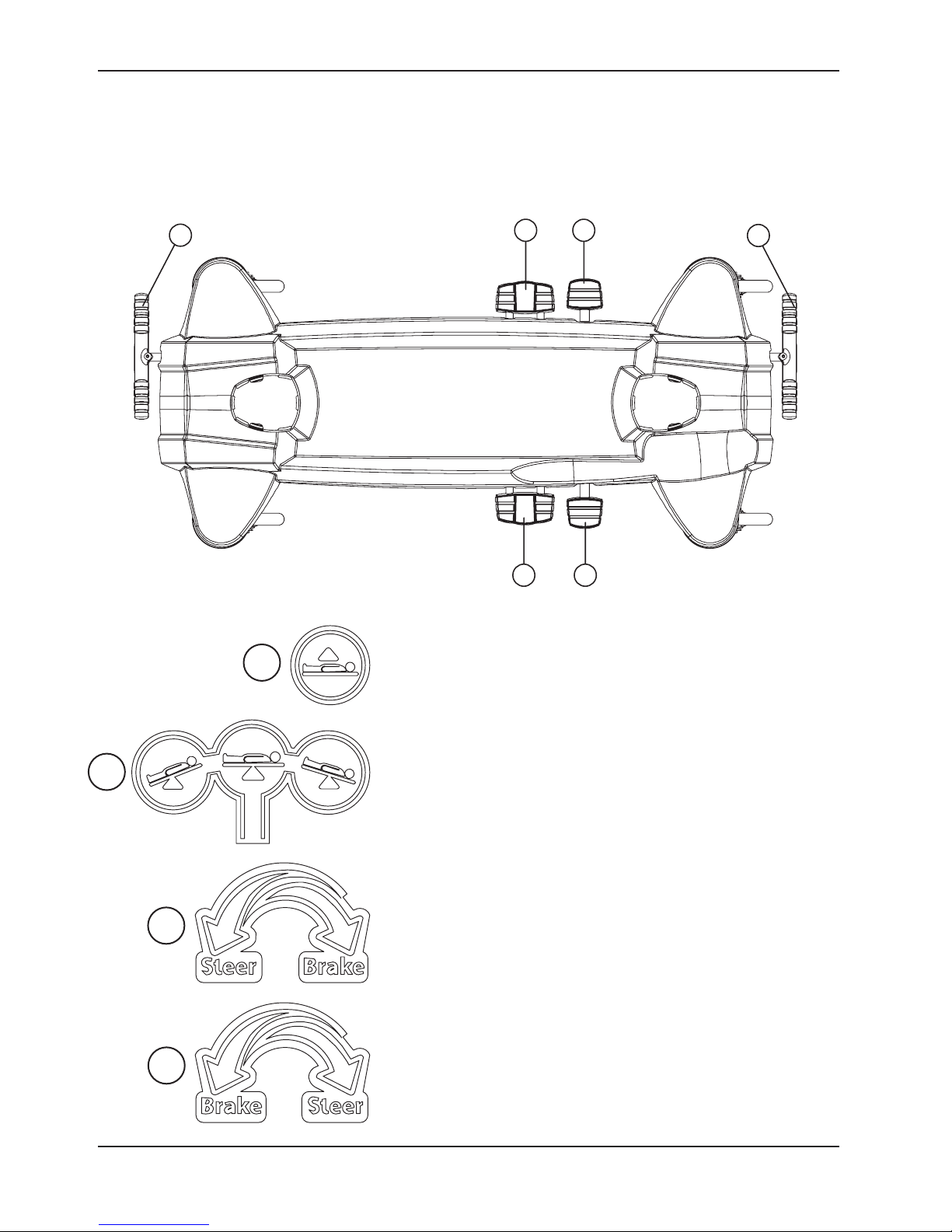
D
C
A
AB
B
HEAD ENDFOOT END
Stretcher Operation
OPERATING THE BASE CONTROLS
To operate the base controls, see Figure 1 to locate which pedals are used for what operation. Pedal (A) raises the
litter. Pedal (B) lowers the stretcher ends. Pedal (C) operates the brake and steer function for the foot end and pedal
(D) operate the brake and steer functions for the head end.
Figure 1 - Stretcher Base Controls
A
B
C
Pump pedal (A) to raise the litter.
Depress in the center of pedal (B) to lower both ends of the stretcher
together.
Depress the side of pedal (B) closest to the foot end of the stretcher
to lower the foot end.
Depress the side of pedal (B) closest to the head end of the stretcher
to lower the head end.
Pedal (C) - Brake and Steer functions (foot end).
D
Return To Table of Contents
12 1025-0 09-0 01 REV E www.stryker.com
Pedal (D) - Brake and Steer functions (head end).
Page 13

Stretcher Operation
RAISING AND LOWERING THE LITTER HEIGHT
CAUTION
Move any equipment that may be in the way before raising or lowering the litter height.
To raise the litter height, pump pedal (A) repeatedly until the desired height is achieved (see Figure 1 on page 12).
To lower both ends of the litter together, depress the center of pedal (B) (see Figure 1 on page 12).
To lower only the head end of the litter, depress the side of pedal (B) closest to the head end (see Figure 1 on page
12).
To lower only the foot end of the litter, depress the side of pedal (B) closest to the foot end (see Figure 1 on page
12).
Note
The base may be equipped with optional variable descent controls. With variable descent controls, the farther you press
down on the pedal, the faster the litter will lower.
WARNING
Patients should be discouraged from sitting directly on the ends of the stretcher. Excessive weight could cause the litter
surface to tip up, possible causing patient injury.
Leave the stretcher litter in the lowest position when the patient is left unattended. Leaving the litter in a raised position
could increase the chance of patient falls and injury.
ADJUSTING TRENDELENBURG / REVERSE TRENDELENBURG POSITIONS
Note
Litter height must be raised first in order to achieve a Trendelenburg or reverse Trendelenburg position.
CAUTION
Remove any equipment that may be in the way before lowering the stretcher.
For Trendelenburg positioning (head down), depress the side of pedal (B) closest to the head end of the stretcher (see
Figure 1 on page 12).
For Reverse Trendelenburg positioning (foot down), depress the side of pedal (B) closest to the foot end (see Figure
1 on page 12).
Note
The higher the litter is before pedal (B) is activated, the greater the Trendelenburg or reverse Trendelenburg angle will
be. (Maximum Trendelenburg angle is +15°. Maximum reverse Trendelenburg angle is -15°).
www.stryker.com 1025- 00 9- 001 REV E 13
Return To Table of Contents
Page 14

No
Charge
Fully
Charged
BATTERY POWER GAUGE
Stretcher Operation
APPLYING THE BRAKE SYSTEM
Note
For user convenience, the brake/steer pedal is located on both the head end and foot end of the stretcher.
WARNING
Always apply the caster brakes when a patient is getting on or off the stretcher. Push on the stretcher to ensure the
brakes are securely locked. Always engage the brakes unless the stretcher is being moved. Injury could result if the
stretcher moves while a patient is getting on or off the stretcher.
To engage the brakes on the head (non-control) end, push fully down on the left side of pedal (D) (see Figure 1 on
page 12).
To engage the brakes on the foot (control) end, push fully down on the right side of pedal (C) (see Figure 1 on page
12).
BATTERY CHARGING AND OPERATION
The unit has two 12 volt batteries to provide power to the drive wheel. The drive wheel will not operate properly if the
batteries are not sufficiently charged. The batteries require approximately 6 hours of charging time when they are fully
discharged.
The batteries are charging whenever the power cord is plugged into a properly grounded, hospital grade power source.
When the unit is stationary, the power cord should be plugged into a power source whenever possible.
There is a battery power gauge at the head end of the litter (see Figure 2). The 7 LED’s illuminate individually to indicate
the level of battery power available. As the batteries are charging, the LED’s will flash in succession until all are flashing
(at 1 second intervals) to indicate the batteries are fully charged.
Figure 2 - Battery Power Gauge
CAUTION
Remove the batteries if the equipment is placed in storage or will remain idle for an extended period of time. Each
battery weighs 25 pounds. To avoid personal injury, use caution when removing the two batteries.
Battery posts, terminals and related accessories contain lead and lead compounds, chemicals known to the State of
California to cause cancer and birth defects or other reproductive harm. Wash hands after handling. Properly dispose
of batteries when required.
Return To Table of Contents
14 1025 -009 -001 REV E www.stryker.com
Page 15

Stretcher Operation
TRANSPORTING THE STRETCHER USING THE DRIVE WHEEL
WARNING
Serious injury can result if caution is not used when
operating the unit. Operate the unit only when all persons
are clear of the electrical and mechanical systems.
Ensure that the brakes are completely released before
attempting to move the unit. Attempting to move the unit
with the brakes actuated could result in injury to the patient
or operator.
To transport the stretcher using the drive wheel:
Unplug the power cord from the power source and 1.
secure the cord on the storage bracket to prevent
entanglement while the unit is in motion. The drive
function will not operate if the power cord is plugged
into the power source.
Engage the drive wheel by rotating the pedal in the 2.
proper direction as shown on the Head End or Foot
End Pedal Directional label. To place the drive wheel
in the neutral position, rotate the pedal until it is level.
Figure 3 - Pedal and Switch
CAUTION
Do not engage the pedal when the drive wheel is resting
on a threshold or other raised area. The force required to
engage the drive wheel will be higher than normal, possibly
causing damage.
Put the “3. On/Drive - Off/Manual” switch in the On
position. There are two LED’s on the drive handle
that indicate whether the unit is ready for driving.
If the • green LED is on, the unit is ready.
If the • amber LED is on, the unit is not ready. If
the unit is not ready for driving, verify that the:
Pedal is in the brake or neutral position.•
Power cord is plugged in the power source.•
Power switch is in the “• Off/Manual”
position.
WARNING
Use caution while maneuvering the unit with the drive
wheel activated. Always ensure there are no obstacles
near the unit while the drive wheel is activated. Injury to
the patient, user or bystanders or damage to the unit or
surrounding equipment could occur if the unit collides with
an obstacle.
Head End Pedal
Directional Label
Foot End Pedal
Directional Label
If unanticipated motion occurs, unplug the power source
and rotate the “On/Drive - Off/Manual” switch to the Off
position.
www.stryker.com 1025- 00 9- 001 REV E 15
On/Drive - Off/Manual Switch Label
Return To Table of Contents
Page 16

Stretcher Operation
A
TRANSPORTING THE STRETCHER USING THE DRIVE WHEEL (CONTINUED)
STORED POSITION
Figure 5 - Drive Handles - Stored Position
Figure 4 - Drive Handles with Motion Release Switches
Grasp the drive handles at the two raised grip areas. Squeeze either of the motion release switches (A) located 4.
under the handles to enable the movement of the drive wheel as shown in Figure 4 and in the Drive Wheel Pedal
and Drive Handle Reference label. Either or both switches will enable movement but both switches must be released
to stop movement.
While continuing to squeeze the switch(es), push the handles away from you or pull the handles toward you to 5.
initiate motion in that direction. The speed of the drive wheel will increase proportionally to the amount of force
applied to the drive handles. When the desired speed is reached, the stretcher will maintain speed and direction
with no extra push force. To accelerate, push or pull the handles again until the desired speed is reached. Relax the
force to a “neutral” position to maintain speed.
To slow down the motion of the stretcher, push or pull the handles in the opposite direction the stretcher is currently 6.
moving.
To stop motion, remove your hands from the switches 7.
and the handles.
Note
The drive wheel does not pivot. The unit cannot be moved
directly sideways with the drive wheel engaged. With the
drive wheel pedal in the neutral position and the unit’s
brakes released, the unit can be moved in any direction
including sideways.
To transport the stretcher without using the drive wheel,
put the pedal in the neutral position and put the “On/ Drive
- Off/Manual” switch in the Off position. This allows the
stretcher to be maneuvered with the assistance of the
Big Wheel® but without power assistance from the ZOOM® drive wheel.
Drive Wheel Pedal and Drive Handle Reference Label
WARNING
Do not attempt to push the unit manually with the drive wheel engaged and the “On/Drive - Off/Manual” switch in the
On position. The unit will be difficult to push and injury could result.
CAUTION
Always unplug the power cord and rotate the “On/Drive - Off/Manual” switch to the Off position before service or
cleaning.
Return To Table of Contents
16 1025- 009- 001 REV E www.stryker.com
Page 17

Stretcher Operation
A
B
B
OPERATING THE GLIDEAWAY™ SIDERAILS
Figure 6 - Siderails
Note
Raising and lowering the siderails safely is a two-handed operation. Use one hand to hold and position the siderail and
the other hand to operate the siderail latch.
WARNING
When lowering the siderail to the collapsed position, keep extremities of patients and staff away from the siderail spindles
or injury could occur.
To raise the siderails: Pull up on the siderail (A) and raise it to the full up position until the latch (B) engages as shown
in Figure 6.
To lower the siderails: Pull up on the latch (B) and guide the siderail to the full down position as shown in Figure 6.
The latches (B) are colored yellow for easy identification.
CAUTION
To avoid injury or damage to the equipment. Do not allow the siderail to lower on its own.
Note
There is a dual siderail latch option available with latches on both ends of the stretcher.
WARNING
After raising the siderails, pull firmly on the siderail to ensure it is securely locked into the up position. Siderails are not
intended to serve as a patient restraint device to keep patients from exiting the unit. Siderails are designed to keep a
patient from inadvertently rolling off the unit. It is the responsibility of the attending medical personnel to determine the
degree of restraint necessary to ensure a patient will remain in place. Failure to utilize the siderails properly could result
in patient injury.
www.stryker.com 1025- 00 9- 001 REV E 17
Return To Table of Contents
Page 18

A
A
Stretcher Operation
OPERATING THE PNEUMATIC FOWLER
Squeeze either or both of the yellow fowler handles (A) for pneumatic assist in lifting the fowler to the desired height as
shown in Figure 7. Remove hand(s) from handle when the desired height is achieved.
The optional drop seat fowler uses the weight of the patient for additional assistance with lifting the fowler. It also helps
keep the patient from sliding toward the foot end of the stretcher when the fowler is raised.
Figure 7 - Pneumatic Fowler
WARNING
Keep hands/fingers clear of the area around the fowler release handles and the fowler frame when lowering. Injury could
result if care is not taken when lowering the fowler.
Return To Table of Contents
18 1025- 009- 001 REV E www.stryker.com
Page 19

A
B
Stretcher Operation
OPERATING THE OPTIONAL KNEE GATCH
FOOT END
Figure 8 - Knee Gatch - Foot End
To raise the knee gatch, pump handle (A) repeatedly to the left as shown in Figure 8.
To lower the knee gatch, pull out handle (B) as shown in Figure 8.
CAUTION
The weight capacity of the knee gatch is 200 pounds. Do not sit or stand on the gatch. Injury or damage to the equipment
could occur.
To prop the foot end of the knee gatch up, lift up the end of the knee gatch, allowing the prop rod to swing down and
engage in the bracket. To release the prop, lift up on the end of the gatch, swing the prop rod toward the head end of
the bed to disengage the bracket and lower the foot end. (See Figure 9)
www.stryker.com 1025- 00 9- 001 REV E 19
Figure 9 - Knee Gatch
Return To Table of Contents
Page 20

Stretcher Operation
A
C
B
A
C
OPERATING THE OPTIONAL 2-STAGE PERMANENTLY ATTACHED I.V. POLE
Figure 11 - Detail of I.V. Pole Latch
Figure 10 - I.V. Pole
Note
The 2-stage permanently attached I.V. pole is an option and may have been installed at either the head, foot or both ends
of the stretcher. The choice was made at the time the stretcher was purchased.
To use the 2-stage permanently attached I.V. pole:
Lift and pivot the pole from the storage position and push down until it is locked into the receptacle.1.
To raise the height of the pole, pull up on the telescoping portion (A) until it locks into place at its fully raised 2.
position.
Rotate the I.V. hangers (B) to desired position and hang the I.V. bags.3.
To lower the I.V. pole, turn the latch (C) until section (A) lowers.4.
CAUTION
To avoid damage, the weight of the I.V. bags should not exceed 40 pounds.
Return To Table of Contents
20 1025- 00 9- 001 REV E www.stryker.com
Page 21

Stretcher Operation
B
D
A
C
E
A
E
B
D
C
OPERATING THE OPTIONAL 3-STAGE PERMANENTLY ATTACHED I.V. POLE
Figure 13 - Detail of I.V. Pole Latch
Figure 12 - I.V. Pole
Figure 14 - Detail of I.V. Pole Grip
Note
The 3-stage permanently attached I.V. pole is an option and may have been installed at either the head, foot or both ends
of the stretcher. The choice was made at the time the stretcher was purchased.
To use the 3-stage permanently attached I.V. pole:
Lift and pivot the pole from the storage position and push down until it is locked into the receptacle.1.
To raise the height of the pole, pull up on the telescoping portion (A) until it locks into place at its fully raised 2.
position.
For a higher I.V. pole, pull up on section (B). Release section (B) at 3. any desired height and it will lock into place.
Rotate the I.V. hangers (C) to the desired position and hang the I.V. bags.4.
To lower the I.V. pole, push up on the red portion of grip (D) while holding onto section (B) until it lowers. Turn latch 5.
(E) until section (A) lowers.
CAUTION
To avoid damage, the weight of the I.V. bags should not exceed 40 pounds.
www.stryker.com 1025- 00 9- 001 REV E 21
Return To Table of Contents
Page 22

A
B
C
D
Stretcher Operation
OPERATING THE OPTIONAL FOOT EXTENSION/DEFIBRILLATOR TRAY
To use as a defibrillator tray, pull out the top knob (A) and pivot
the tray (B) over the foot extension (C) until the tray extends
flat over the foot end of the stretcher as shown in Figure 15.
To use as a foot extension, pull out knob (A) and pivot the
defibrillator tray back until it locks against the foot extension
(C). While holding onto the assembly, pull out the bottom knob
(D) and lower the foot extension down until it is flat as shown
in Figure 15.
WARNING
If the stretcher is equipped with the optional foot end I.V. pole, the
I.V. pole must be in the raised position when the foot extension/
defibrillator tray is installed. If the I.V. pole is not raised, the foot
extension will not function properly and injury could occur.
If the stretcher is equipped with the optional foot end push
handles, use caution while the foot extension/defibrillator tray
is installed to avoid pinching your fingers.
Figure 15 - Optional Foot Extension/
Defibrillator Tray - Foot End
Return To Table of Contents
22 1025- 00 9- 001 REV E www.stryker.com
Page 23

Stretcher Operation
OPERATING THE OPTIONAL SERVING TRAY
Figure 16 - Optional Serving Tray
FOOT
END
Figure 17 - Optional Serving Tray -
Foot End
To use the optional serving tray, pull out on either end of the serving tray to extend it to the proper width to fit on top
of the stretcher siderails as shown in Figure 16.
To store the serving tray in the optional serving tray holder/foot board, push in both ends of the serving tray and slide
it into the holder as shown in Figure 17.
CAUTION
To avoid damage, do not put items weighing more than 30 pounds on the serving tray.
www.stryker.com 1025- 00 9- 001 REV E 23
Return To Table of Contents
Page 24

1.
3.
2.
4.
.
Weigh
Zero
lb/kg
Stretcher Operation
OPERATING THE OPTIONAL SCALE SYSTEM
Battery Charge Level Indicator
Display -1. Displays patient weight, unit of measurement and battery status.
“Zero” -2. Push and hold for 2 seconds to zero the scale system before putting a patient on the stretcher. If the
display flashes “hold”, press and hold the “Zero” button again until the display reads “rEL” (release). Release the
“Zero” button. The display flashes “000.0”, then displays “000.0”. The system is not zeroed until the “000.0” stops
flashing. For the most accurate results, always zero the scale system before putting a new patient on the stretcher.
The display will shut off after approximately 40 seconds.
“Weigh” -3. Push to weigh the patient. The display will show the patient’s weight for approximately 40 seconds before
turning off.
“lb/kg” -4. Push to display patient weight in pounds or kilograms.
Note
Do not touch the stretcher while the scale system is weighing or zeroing.
The patient must remain still while the system is weighing. If the patient is moving, the system will try for 20 seconds to
get a stable weight or zero value before displaying the error message .
If there is a loose connection or a malfunctioning component, the display will show “Err”. Attempt the function again. If
the system is functional, “Good” will display and the scale system is ready to use. If the malfunction is still present, the
display shows “Err” again. Call Stryker technical support at 800-327-0770.
For the most accurate results, weigh the patient with the litter at zero degrees of Trend.
SYMBOL ACTION DISPLAY
Press and release ”WEIGH”.
Press and hold ”ZERO”
Release ”ZERO”
- - - -
“XXX.X lb
“hold
“rEL”
“000.0” (flashing)
“000.0 (solid)
kilograms, press and release ”lb/kg”
Return To Table of Contents
24 1025- 00 9- 001 R EV E www.stryker.com
To convert the patient’s weight to
Repeat to return to pounds. “XXX.X lbs
“XXX.X kg
Page 25

Stretcher Operation
USING THE OPTIONAL SCALE SYSTEM BATTERIES
Note
To avoid completely draining the batteries and having the optional scale system shut down, replace the batteries whenever
only one of the charge indicator bars on the display is black (see “Operating the Optional Scale System” on page
24).
Remove the two Phillips head screws holding the battery compartment cover on the display assembly.1.
Replace all four AA batteries, being sure to install the positive and negative poles as indicated on the battery holder. 2.
Standard alkaline batteries are recommended. Do not mix old and new batteries or mix different types of batteries.
Properly dispose of the old batteries in accordance with local regulations.
Reinstall the screws and the cover. 3.
If the display is flashing “Lo Batt”, the batteries are drained and the scale system is disabled. Replace the batteries with
four new AA batteries as described above.
www.stryker.com 1025- 00 9- 001 REV E 25
Return To Table of Contents
Page 26

Cleaning
These instructions are intended to provide recommended cleaning methods for stretcher mattresses. They outline
proper care that will provide effective cleaning and disinfecting of mattresses between patients and prolong the life of
the mattress.
RECOMMENDED CLEANING METHOD
Hand-wash all surfaces of the mattress with warm water and mild detergent cleaner. •
Dry thoroughly. •
Apply disinfectant solution either by spray, solution or pre-impregnated wipes (do not soak mattress).•
Clean per hospital protocol for bed mattresses. •
Wipe up excess disinfectant.•
Rinse with clean water. •
Allow surface to dry.•
RECOMMENDED DISINFECTANTS
IMPORTANT: DILUTE ALL DISINFECTANTS IN ACCORDANCE WITH MANUFACTURER’S DIRECTIONS
When used in concentrations recommended by the manufacturer, diluted bleach, diluted phenolic, or diluted quaternary
germicidal disinfectants are recommended.
Chlorine Bleach, typically 5.25% Sodium hypochlorite, should be used at a dilution ratio of 1 part bleach to 10 parts
water.
RINSE OFF CORROSIVE CLEANERS
These products are NOT considered mild detergents. They are corrosive in nature and may cause damage to your
stretcher mattress if used improperly. Mattresses must be rinsed with clean water and dried thoroughly after using
corrosives such as quaternary, phenolic, or chlorine bleach. Failure to properly rinse and dry the mattress leaves a
corrosive residue on the surface, likely causing premature corrosion.
Iodophor type disinfectants are not recommended for use because staining may result.
The following table lists the recommended cleaner types for each mattress cover material (see definitions below):
Vinyl Mattress Cover Polyurethane Mattress Cover
Recommended Phenolics Quaternary, Quat/Isopropyl
Acceptable Quaternary, Chlorine Bleach (1:10) Chlorine Bleach (1:10)
Not Recommended Quat/Isopropyl Phenolics
Quaternary Cleaners: identified by ingredients containing the phrase “…yl ammonium chloride”
Quat/Isopropyl Cleaners: identified by a quaternary ingredient above plus isopropyl alcohol
Phenolic Cleaners: identified by ingredients containing the suffix “-phenol”
Chlorine Bleach: known generically as “Sodium hypochlorite”
Return To Table of Contents
26 1025-009-001 REV E www.stryker.com
Page 27

Cleaning
SPECIAL INSTRUCTIONS
Velcro: to clean and disinfect Velcro, saturate with disinfectant, rinse with water, and allow it to evaporate.
Soils or Stains: use neutral soaps and warm water. Do not use harsh cleansers, solvents or abrasive cleaners.
Hard-To-Clean Spots: use standard household/vinyl cleansers and a soft bristle brush on troublesome spots or stains.
Pre-soak heavy, dried-on soil.
Laundering is NOT RECOMMENDED: laundering may substantially decrease the useful life of the mattress.
DO NOT STEAM CLEAN, PRESSURE WASH, HOSE OFF OR ULTRASONICALLY CLEAN MATTRESSES.
Using these methods of cleaning is not recommended and may void this product’s warranty.
REMOVAL OF IODINE STAINS
Make a solution of 1−2 Tablespoons Sodium thiosulfate in a pint of warm water and use it to wipe the stained area. 1.
Clean the stain as soon as possible after it occurs. If stains are not immediately removed, allow solution to soak or
stand on the surface before wiping.
Rinse surfaces which have been exposed to the solution with clear water before returning mattress to service. 2.
NOTE
Failure to follow the above directions when using these types of cleaners may void this product’s warranty.
www.stryker.com 1025- 00 9- 001 REV E 27
Return To Table of Contents
Page 28

CHECKLIST
Preventative Maintenance
______
______
______
______
______
______
______
______
______
______
______
______
______
______
______
______
______
______
______
______
______
______
______
______
______
______
______
______
______
All fasteners secure.
Siderails move and latch properly.
All casters lock with brake pedal engaged.
All casters secure and swiveling properly.
Fowler operates and latches properly.
Trendelenburg/Reverse Trendelenburg operating properly.
Ground chain intact.
No leaks at hydraulic connections.
Hydraulic jacks holding properly.
Hydraulic oil level sufficient.
Body restraints working properly.
I.V. pole intact and operating properly.
Oxygen bottle holder intact and operating properly.
No rips or cracks in mattress cover.
Engage the drive wheel and ensure it is operating properly.
No excessive play in the drive handles.
Press the handle switches. Unit should not move unless the handles are pushed forward or pulled back.
Press the handle switches. Move the handles forward and back and verify the unit responds properly.
Confirm battery powered functionality.
No cables worn, pinched or frayed.
All electrical connections tight.
All grounds secure to the frame.
Ground impedance not more than 100 milliohms max: Test point(s) include electronics enclosure and motor
chassis mounted to base of unit.
Current leakage not more than 300 microamperes (per UL 60601-1).
Batteries sufficiently charged (optional scale system).
Display housing intact and not damaged (optional scale system).
Display label intact and not damaged (optional scale system).
Load cells intact and not damaged (optional scale system).
Scale calibrated properly. Recalibrate, if necessary (optional scale system).
Stretcher Serial Number:
Completed by: _______________________________________ Date: _________________
Note
Preventative maintenance should be performed at a minimum of annually. A preventative maintenance program should
be established for all Stryker Medical equipment. Preventative maintenance may need to be performed more frequently
based on the usage level of the product.
Return To Table of Contents
28 1025-009-001 REV E www.stryker.com
Page 29

Notes
www.stryker.com 1025- 00 9- 001 REV E 29
Return To Table of Contents
Page 30

Warranty
LIMITED WARRANTY
Stryker Medical Division, a division of Stryker Corporation, warrants to the original purchaser the SM304 M-Series
Stretcher to be free from defects in material and workmanship for a period of two (2) year after date of delivery.
Stryker’s obligation under this warranty is expressly limited to supplying replacement parts and labor for, or replacing,
at its option, any product which is, in the sole discretion of Stryker, found to be defective. If requested by Stryker,
products or parts for which a warranty claim is made shall be returned prepaid to the factory. Any improper use or
any alteration or repair by others in such manner as in Stryker’s judgment affects the product materially and adversely
shall void this warranty. Any repair of Stryker products using parts not provided or authorized by Stryker shall void this
warranty. No employee or representative of Stryker is authorized to change this warranty in any way.
Stryker Medical Stretcher products are designed for a 10 year expected service life under normal use, conditions,
and with appropriate periodic maintenance as described in the maintenance manual for each device. Stryker warrants
to the original purchaser that the welds on its Stretcher products will be free from structural defects for the expected
10 year life of the Stretcher product as long as the original purchaser owns the product.
This statement constitutes Stryker’s entire warranty with respect to the aforesaid equipment. Stryker makes no
other warranty or representation, either expressed or implied, except as set forth herein. There is no warranty
of merchantability and there are no warranties of fitness for any particular purpose. In no event shall Stryker be
liable here under for incidental or consequential damages arising from or in any manner related to sales or use of
any such equipment.
TO OBTAIN PARTS AND SERVICE
Stryker products are supported by a nationwide network of dedicated Stryker Field Service Representatives. These
representatives are factory trained, available locally, and carry a substantial spare parts inventory to minimize repair
time. Simply call your local representative, or call Stryker Customer Service USA at 1-800-327-0770.
SERVICE CONTRACT COVERAGE
Stryker has developed a comprehensive program of service contract options designed to keep your equipment operating
at peak performance at the same time it eliminates unexpected costs. We recommend that these programs be activated
before the expiration of the new product warranty to eliminate the potential of additional equipment upgrade charges.
A Service Contract helps to:
Ensure equipment reliability•
Stabilize maintenance budgets•
Diminish downtime•
Establish documentation for JCAHO•
Increase product life•
Enhance trade-in value•
Address risk management and safety•
Return To Table of Contents
30 1025- 009- 001 REV E www.stryker.com
Page 31

Warranty
SERVICE CONTRACT PROGRAMS
Stryker offers the following service contract programs:
Service Agreement Options Gold Silver PM* only
Annually scheduled preventative maintenance
All parts**, labor, and travel X X
Unlimited emergency service calls X X
Priority one contact: two hour phone response X X
Most repairs will be completed within 3 business days X X
JCAHO documentation X X X
On-site record of PM & emergency service X X
Factory-trained Stryker service technician X X X
Stryker authorized parts used X X X
Service during regular business hours (8-5) X X X
* Replacement parts and labor for products under PM contract will be discounted.
** Does not include any disposable items, I.V. poles (except for Stryker HD permanent poles), mattresses, or damage resulting from abuse.
Stryker Medical also offers personalized service contracts.
Pricing is determined by age, location, model and condition of product.
For more information on our service contracts,
please call your local representative.
X X
RETURN AUTHORIZATION
Merchandise cannot be returned without approval from the Stryker Customer Service Department. An authorization
number will be provided which must be printed on the returned merchandise. Stryker reserves the right to charge
shipping and restocking fees on returned items. Special, modified, or discontinued, items not subject to return.
DAMAGED MERCHANDISE
ICC Regulations require that claims for damaged merchandise must be made with the carrier within fifteen (15) days of
receipt of merchandise. Do not accept damaged shipments unless such damage is noted on the delivery receipt at
the time of receipt. Upon prompt notification, Stryker will file a freight claim with the appropriate carrier for damages
incurred. Claim will be limited in amount to the actual replacement cost. In the event that this information is not received
by Stryker within the fifteen (15) day period following the delivery of the merchandise, or the damage was not noted on
the delivery receipt at the time of receipt, the customer will be responsible for payment of the original invoice in full.
Claims for any short shipment must be made within thirty (30) days of invoice.
INTERNATIONAL WARRANTY CLAUSE
This warranty reflects U.S. domestic policy. Warranty outside the U.S. may vary by country. Please contact your local
Stryker Medical representative for additional information.
Return To Table of Contents
www.stryker.com 1025- 00 9- 001 REV E 31
Page 32

Recycling Passport
1040−060−060
Standard Power Cord
ASSEMBLY PART NUMBER: 1040-010-101
(Reference Only)
A
Item Recycling/Material Code Important Information Qty
A Power Cord (1040-060-060,
1040-060-050)
Return To Table of Contents
32 1025-009-001 REV E www.stryker.com
1
Page 33

Recycling Passport
ASSEMBLY PART NUMBER: 1040-010-101
(Reference Only)
A
Item Recycling/Material Code Important Information Qty
A Coil Cable Plug (1040-010-801) 1
www.stryker.com 1025- 00 9- 001 REV E 33
Return To Table of Contents
Page 34

Recycling Passport
ASSEMBLY PART NUMBER: 1040-006-301
(Reference Only)
A
Item Recycling/Material Code Important Information Qty
A Cam Position Cable (1040-010-807) 1
Return To Table of Contents
34 1025-009-001 REV E www.stryker.com
Page 35

Recycling Passport
ASSEMBLY PART NUMBER: 1040-020-101
(Reference Only)
A
Item Recycling/Material Code Important Information Qty
A Manual Override Switch (1040-010-830) 1
www.stryker.com 1025- 00 9- 001 REV E 35
Return To Table of Contents
Page 36

Recycling Passport
ASSEMBLY PART NUMBER: 1040-007-210
(Reference Only)
A
Item Recycling/Material Code Important Information Qty
A Switch Cable (1040-050-805) 1
Return To Table of Contents
36 1025- 00 9- 001 REV E www.stryker.com
Page 37

Recycling Passport
ASSEMBLY PART NUMBER: 1040-020-101
(Reference Only)
A
Item Recycling/Material Code Important Information Qty
A Motor Drive Unit (1040-010-820) 1
Return To Table of Contents
www.stryker.com 1025- 00 9- 001 REV E 37
Page 38

Recycling Passport
ASSEMBLY PART NUMBER: 1040-020-101
(Reference Only)
A
Item Recycling/Material Code Important Information Qty
A Circuit Board (1040-210-859) 1
Return To Table of Contents
38 1025- 00 9- 001 REV E www.stryker.com
Page 39

Recycling Passport
ASSEMBLY PART NUMBER: 1040-007-200, 1040-007-300
(Reference Only)
A
B
Item Recycling/Material Code Important Information Qty
A Circuit Board (1040-050-125) 1
B Load Cell (3002-307-057) 1
www.stryker.com 1025- 00 9- 001 REV E 39
Return To Table of Contents
Page 40

Recycling Passport
ASSEMBLY PART NUMBER: 1040-020-101
(Reference Only)
A
Item Recycling/Material Code Important Information Qty
A Batteries (1040-010-870) 2
Return To Table of Contents
40 1025- 009- 001 RE V E www.stryker.com
Page 41

Page 42

UNITED STATES
UNITED STATES
Stryker Medical
Stryker Medical
3800 E. Centre Ave.,
3800 E. Centre Ave.,
Portage, Michigan 49002
Portage, Michigan USA
USA
49002
CANADA
CANADA
Stryker Canada
Stryker Canada
45 Innovation Drive
45 Innovation Drive
Hamilton, Ontario L9H 7L8
Hamilton, Ontario Canada
Canada
L9H 7L8
EC REP
EC REP
European Representative
European Representative
Stryker France
Stryker France
ZAC Satolas Green Pusignan
ZAC Satolas Green Pusignan
Av. De Satolas Green
Av. De Satolas Green
69881 MEYZIEU Cedex
69881 MEYZIEU Cedex
France
France
2006/XX XXXX-XXX-XXX REV X www.stryker.com
2009/01 1025-009-001 REV E www.stryker.com
 Loading...