

Page 1
X8000 Light Source
220-200-000
Page 2

Page 3

X8000 Light Source
User Guide
Contents
Warnings and Cautions ......................................... 2
Symbol Definitions ............................................................................ 4
Product Description and Intended Use ................. 5
Setup and Assembly ............................................. 8
Connecting the AC Power Cable ...................................................... 8
Connecting the Light Cable .............................................................. 8
System Operation ............................................... 10
Powering the System On and Off ................................................... 10
Selecting the Operation Mode ........................................................ 11
Adjusting the Brightness ................................................................. 11
Visual Display .................................................................................. 12
Language Selection ........................................................................ 13
Safety Shutoff ................................................................................. 13
Checking the ESST Feature ............................................................ 14
Using the X8000 with a Voice-Controlled System Interface ........... 15
Using the SFB Serial Interface ........................................................ 15
Troubleshooting .............................................................................. 16
Cleaning and Maintenance ................................. 18
Cleaning the X8000 ......................................................................... 18
Caring for the Bulb Module ............................................................. 18
Replacing the Bulb Module ............................................................ 18
Replacing the Fuses ....................................................................... 20
Disposing of the X8000 ................................................................... 20
Technical Specifications ..................................... 21
Electromagnetic Compatibility ........................................................ 22
Warranty ............................................................. 26
Service and Claims ............................................. 27
1
Page 4
Warnings and Cautions
Please read this manual and follow its instructions carefully. Certain symbols and
the words warning, caution, and note carry special meanings and should be
carefully reviewed:
W
ARNING THE PERSONAL SAFETY OF THE PATIENT OR USER MAY BE
INVOLVED. DISREGARDING THIS INFORMATION COULD RESULT IN
SERIOUS INJURY TO THE PATIENT OR USER.
Caution Special procedures or precautions must be followed to avoid
damaging the instrument.
Note Special information to make maintenance easier or important
information more clear.
An exclamation mark within a triangle is intended to alert the
user to the presence of important operating and maintenance
instructions in the manual.
A lightning bolt within a triangle is intended to warn of the
presence of hazardous voltage. Refer all service to authorized
personnel.
W
ARNING IMPORTANT SAFETY NOTICE: BEFORE OPERATING THIS
DEVICE, PLEASE READ THIS OPERATING MANUAL THOROUGHLY
AND CAREFULLY. WHEN USING THIS DEVICE WITH A LIGHT SOURCE,
FIRE AND/OR SEVERE INJURY MAY RESULT TO THE PATIENT, USER
OR INANIMATE OBJECTS, IF THE INSTRUCTIONS IN THIS MANUAL
ARE NOT FOLLOWED. ALL LIGHT SOURCES, INCLUDING THE X8000,
CAN GENERATE SIGNIFICANT AMOUNTS OF HEAT (EXCEEDING 41°C
/ 106°F)
CABLE TIP, AND/OR NEAR THE LIGHT CABLE ADAPTER. HIGHER
LEVELS OF BRIGHTNESS FROM THE LIGHT SOURCE RESULT IN
HIGHER LEVELS OF HEAT. ALWAYS ADJUST THE BRIGHTNESS LEVEL
OF THE CAMERA AND THE MONITOR, BEFORE ADJUSTING THE
BRIGHTNESS LEVEL OF THE LIGHT SOURCE. ADJUST THE
BRIGHTNESS LEVEL OF THE LIGHT SOURCE TO THE MINIMUM
BRIGHTNESS NECESSARY TO ADEQUATELY ILLUMINATE THE
SURGICAL SITE. IN ADDITION, ADJUST THE INTERNAL SHUTTER OF
THE CAMERA HIGHER IN ORDER TO RUN THE LIGHT SOURCE AT A
LOWER INTENSITY. AVOID TOUCHING THE SCOPE TIP OR THE LIGHT
CABLE TIP TO THE PATIENT, AND NEVER PLACE THEM ON TOP OF
THE PATIENT, AS DOING SO MAY RESULT IN BURNS TO THE PATIENT
OR USER. IN ADDITION, NEVER PLACE THE SCOPE TIP, THE SCOPE
LIGHT POST, THE LIGHT CABLE ADAPTER, OR THE LIGHT CABLE TIP
ON THE SURGICAL DRAPES OR OTHER FLAMMABLE MATERIAL, AS
AT THE SCOPE TIP, THE SCOPE LIGHT POST, THE LIGHT
2
Page 5
DOING SO MAY RESULT IN FIRE. ALWAYS PLACE THE LIGHT SOURCE
IN STANDBY MODE WHENEVER THE SCOPE IS REMOVED FROM THE
LIGHT CABLE OR THE DEVICE IS UNATTENDED. THE SCOPE TIP,
SCOPE LIGHT POST, LIGHT CABLE ADAPTER, AND LIGHT CABLE TIP
WILL TAKE SEVERAL MINUTES TO COOL OFF AFTER BEING PLACED
IN STANDBY MODE, AND THEREFORE MAY STILL RESULT IN FIRE OR
BURNS TO THE PATIENT, USER, OR INANIMATE OBJECTS.
W
ARNING TO HELP AVOID POTENTIAL SERIOUS INJURY TO THE USER AND
THE PATIENT AND/OR DAMAGE TO THIS DEVICE, THE USER MUST:
1. Read this operating manual thoroughly, especially the warnings, and be
familiar with its contents prior to using this equipment.
2. Carefully unpack the unit and check if any damage occurred during
shipment. If damage is detected, please refer to the “Service and Claims”
section in this manual.
3. Be a qualified physician, having complete knowledge of the use of this
equipment.
4. Test this equipment prior to a surgical procedure. This unit was fully
tested at the factory before shipment.
5. Attempt no internal repairs or adjustments that are not specifically
detailed in the Troubleshooting, Cleaning and Maintenance sections of
this operating manual.
6. Never sterilize any part of the X8000 console.
7. Disconnect the X8000 from the electrical outlet when inspecting the fuses.
8. No modification of this equipment is allowed.
9. To avoid risk of electric shock, this equipment must only be connected
to a supply mains with protective earth ground.
10. Do not position the console so that it is difficult to disconnect the power
cord from the supply mains.
11. Never use this equipment in the presence of flammable or explosive gases.
The warranty is void if any of these warnings or cautions contained in this manual
are disregarded. The user must also be ensure that:
• Readjustments, modifications, and/or repairs are carried out
exclusively by Stryker Endoscopy.
• The electrical installation of the relevant operating room complies
with the applicable IEC, CEC, and NEC requirements.
W
ARNING FEDERAL LAW (UNITED STATES OF AMERICA) RESTRICTS THIS
DEVICE TO USE BY, OR ON ORDER OF, A PHYSICIAN.
3
Page 6
Symbol Definitions
Type CF Applied Part
Protective Earth Ground
Equipotentiality
Denotes compliance to CSA 22.2 No.601.1-M90 and UL60601-1.
This symbol indicates that the waste of electrical and electronic
equipment must not be disposed as unsorted municipal waste
and must be collected separately. Please contact the
manufacturer or other authorized disposal company to
decommission your equipment.
Caution: Surface may be hot
The user must read the provided instructions to safely operate
the device. Disregarding the information could result in serious
injury to the patient or user.
Consult instructions for use
Caution (consult instructions for use)
Power on/off (alternates when button is pushed)
Alternating current
Device recycling code (applicable in China)
Relative humidity limitation
4
Page 7
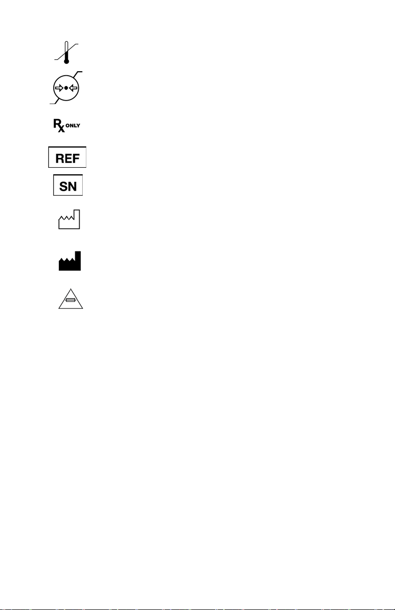
Temperature limitation
Pressure limitation
Federal law (USA) restricts this device to use by, or on order of, a
physician
Product catalog number
Product serial number
Date of manufacture
Legal manufacturer
Fuse rating
Product Description and Intended Use
The Stryker X8000 Light Source is a light-generating unit designed to illuminate
surgical sites during endoscopic applications. The X8000 uses a 300-watt xenon
bulb to generate bright, crisp light, which it delivers to the surgical site via a
fiberoptic light cable. The X8000 is compatible with all Stryker light cables, and,
with the proper light cable and adapters, can connect to any flexible or rigid
endoscope.
The X8000 is equipped with Electronic Scope Sensing Technology (ESST), a
special safety feature that helps prevent accidental burns caused by a light cable
that is not connected to the scope. For more information, refer to the section
“Checking the ESST Feature”. When operated with an ESST light cable, the X8000
senses when the scope and the light cable are separated and places the light source
in Standby mode. In Standby mode, the X8000 will reduce light output to a
minimum, preventing the light cable from generating excessive heat.
5
Page 8
ARNING THE SCOPE TIP, SCOPE LIGHT POST, LIGHT CABLE ADAPTER, AND
1
57
98
6
3
2
4
W
LIGHT CABLE TIP WILL TAKE SEVERAL MINUTES TO COOL OFF
AFTER BEING PLACED IN STANDBY MODE AND THEREFORE MAY
STILL RESULT IN FIRE AND/OR BURNS TO THE PATIENT, USER, OR
AN INANIMATE OBJECT IF NOT USED PROPERLY. DO NOT PLACE
THE SCOPE OR THE LIGHT CABLE ON THE PATIENT OR ON THE
DRAPES OR OTHER FLAMMABLE MATERIAL, EVEN WHEN THE
DEVICE IS IN STANDBY MODE.
The Stryker X8000 Light Source consists of one of each of the following:
• light source console
•power cord
• xenon bulb module (spare or replacement bulb modules can be
purchased separately as P/N 220-201-000)
The features of the X8000 console are described below (see Figures 1 and 2).
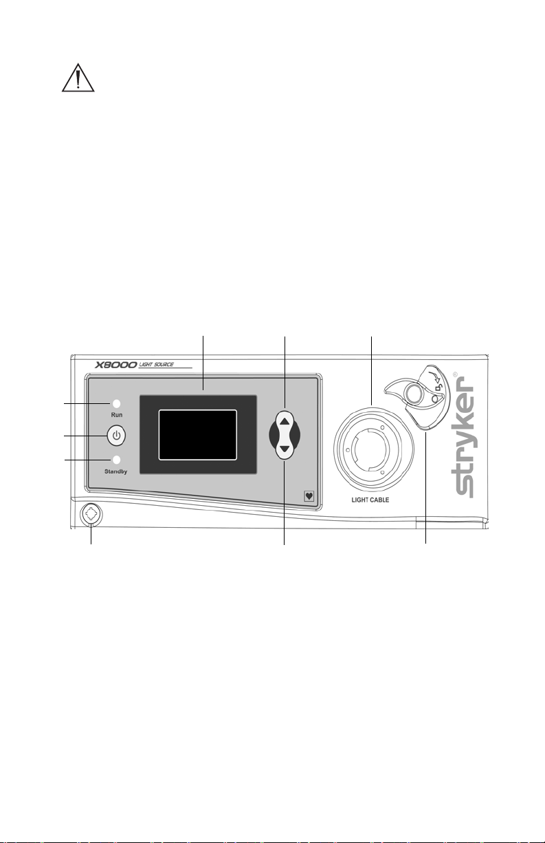
Figure 1 Front panel of the X8000 console
1. Power Button: Powers the unit on and off.
2. Standby LED: Illuminates when the unit is operating in the Standby
mode. In Standby mode, light output is reduced to a minimum level.
3. Mode Button: Selects either Standby or Run mode when pressed.
Standby is the default mode when the light source is powered on.
4. Run LED: Illuminates when the unit is operating in the Run mode. In
Run mode, light output is determined by the up and down switches.
5. LCD: Indicates the light intensity level (0-100%), bulb hours and
language.
6
Page 9
6. Up Button: Increases light intensity in Run mode.
Stryker Endoscopy
5900 Optical Court
San Jose, CA 95138 USA
U.S. Patents:
5850496, 6110107, 6689050
Other patents pending
MADE IN USA
SIDNE
10
12, 13
11
14
7. Cable Clamp: Grasps the light-source end of an inserted fiberoptic
cable. (When no cable is inserted, the bulb automatically turns off to
save bulb hours.)
8. Jaw Handle: Opens the fiberoptic-cable holder.
9. Down Button: Decreases light intensity in Run mode.
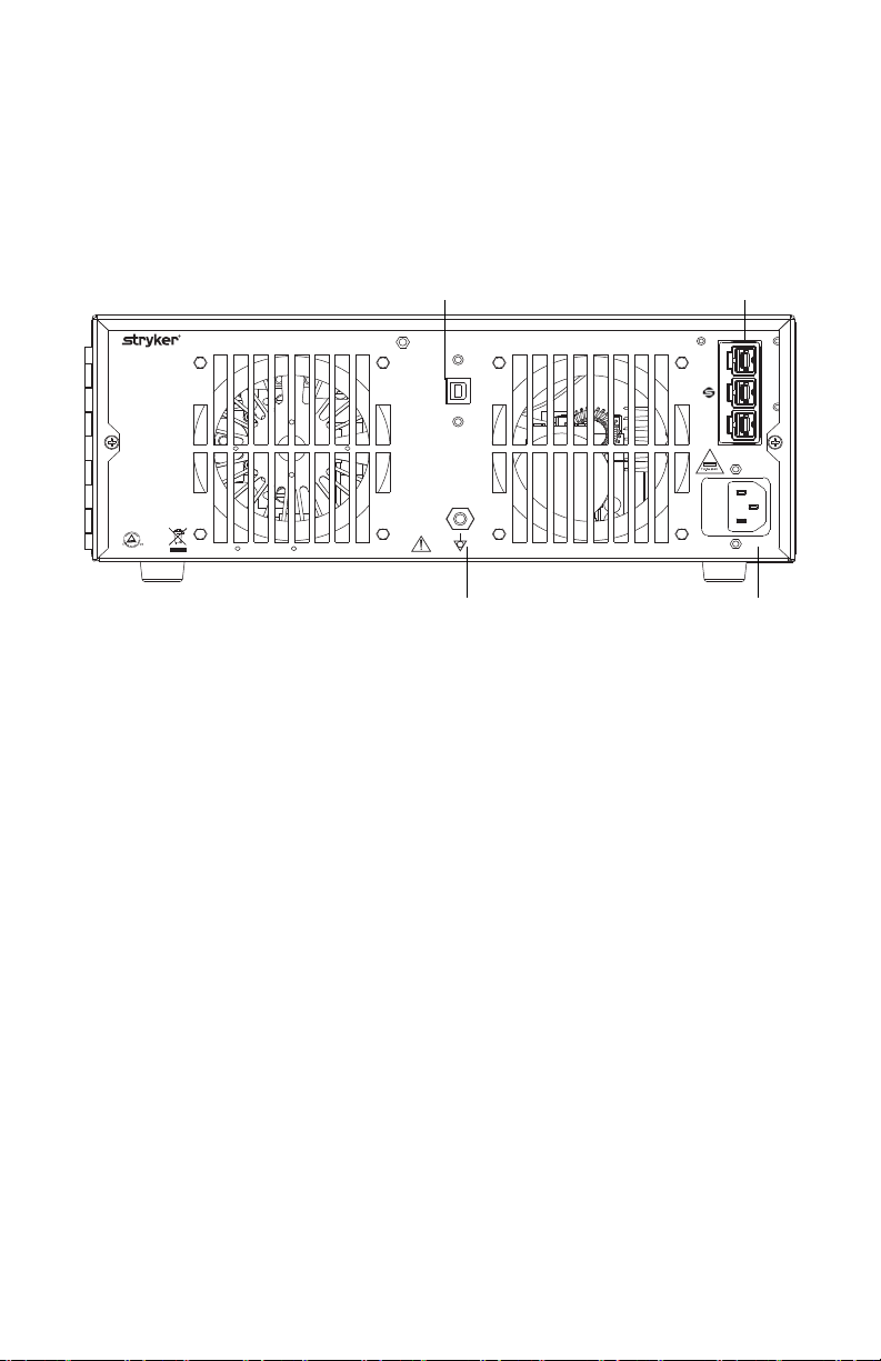
Figure 2 Rear panel of the X8000 console
10. Voi c e-C ontr o l Port : Connects to Stryker voice-control systems.
11.
SFB Series Connectors
: Enables FireWire connection with Stryker
FireWire devices. Provides connection for remote diagnoses and future
software upgrades.
12. AC Inlet: Connects to the provided power cord for AC power supply.
13. Fuse Holder: Contains two T 5.0 AH 250 V fuses.
14. Equipotentiality Plug: Provides a grounding post for common
grounding with other equipment. Connects to a potential equalization
conductor. The resulting medical electrical system shall follow all
applicable IEC 60601-1 requirements.
7
Page 10
Setup and Assembly
Note Your local Stryker Endoscopy sales representative will perform
inservice training at your convenience to instruct you and your
staff on the safe and effective operation and maintenance of the
X8000, and to help set up the equipment. Please contact your
local Stryker Endoscopy sales representative to schedule an
inservice after the equipment has arrived.
Note When selecting a setup location for the X8000, consult the
“Electromagnetic Compatibility” section included in this manual
to determine the best location.
To set up the X8000, make the following connections:
• Connect the AC power cable
• Connect the light cable
Connecting the AC Power Cable
1. Plug in the AC power cord to the AC Inlet on the rear console panel.
2. Plug in the other end of the AC cord to a hospital-grade outlet.
W
ARNING WHEN THE X8000 IS INTERCONNECTED WITH OTHER MEDICAL
ELECTRICAL EQUIPMENT, LEAKAGE CURRENTS MAY BE ADDITIVE.
T
O MINIMIZE LEAKAGE CURRENT THAT MAY TRAVEL TO THE
PATIENT OR USER, ANY TYPE CF APPLIED PART SHOULD BE USED
ONLY WITH OTHER TYPE CF APPLIED PARTS. ENSURE ALL
SYSTEMS ARE INSTALLED ACCORDING TO THE REQUIREMENTS OF
IEC 60601-1-1.
Connecting the Light Cable
WARNING USE ONLY NONCONDUCTIVE FIBEROPTIC CABLES WITH THE
X8000
TO MAINTAIN ELECTRICAL ISOLATION.
Note The X8000 Light Source is compatible with all Stryker Light
Cables.
8
Page 11
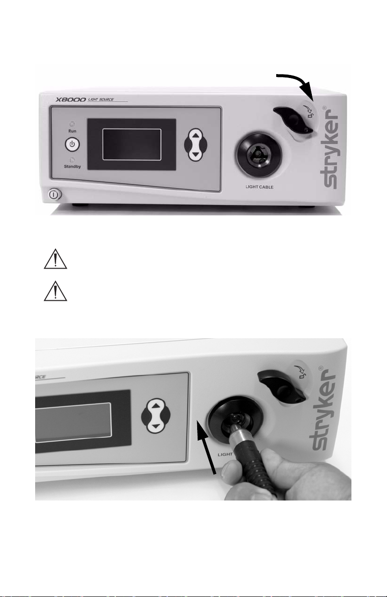
1. Lock open the cable clamp by turning the jaw handle clockwise until it
stops (see Figure 3).
Figure 3 Locking open the cable clamp
WARNING KEEP FINGERS AWAY FROM THE CABLE CLAMP AS THE CLAMP
MAY INADVERTENTLY DEPLOY AND CAUSE INJURY.
W
ARNING DO NOT LOOK DIRECTLY INTO THE CABLE PORT. THE HIGH-
INTENSITY LIGHT MAY CAUSE DAMAGE TO THE EYES.
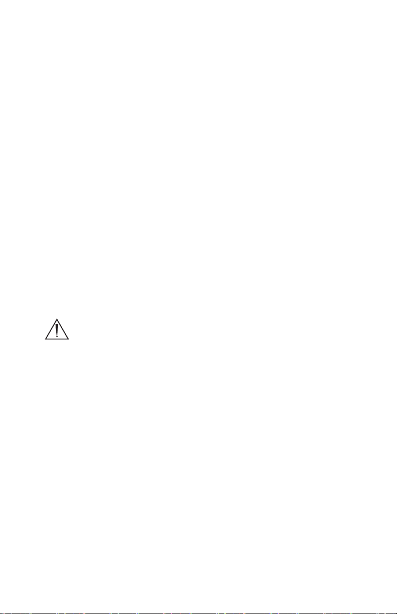
2. Insert a clean, dry fiberoptic cable into the cable port until the jaw latch
releases and the jaw clamps the cable in place (see Figure 4). Pull gently
on the fiberoptic cable to test that it is securely seated in the cable port.
Figure 4 Inserting the light cable into the cable port
3. Connect an endoscope to the opposite end of the fiberoptic cable.
9
Page 12

4. To remove the light cable, press the Mode button to put the unit into Standby
mode. Then turn the jaw handle clockwise until it latches fully open.
WARNING IF THE LIGHT SOURCE IS NOT IN STANDBY MODE PRIOR TO
REMOVING THE CABLE, THE HIGH INTENSITY LIGHT WILL SHINE
DIRECTLY OUT OF THE LIGHT SOURCE BRIEFLY BEFORE TURNING
OFF, POSSIBLY CAUSING INJURY TO THE USER'S EYES.
Note The Light Source will default to Standby mode when a light cable
is inserted.
System Operation
Note Before operating the X8000, see the “Setup and Assembly” section
of this manual.
Powering the System On and Off
Caution Do not power the system on and off in rapid succession. Allow
the bulb to run for at least five minutes once it has been
powered on, before turning the power off. Failure to do so can
cause the bulb to rapidly darken and fail.
To power on the X8000:
1. Confirm that the X8000 contains a properly installed bulb. The bulb
handle must be turned all the way to the left, to ensure proper latching. If
no bulb is installed, follow the instructions in the “Replacing the Bulb”
section of this manual before proceeding.
2. Press the power switch on the front panel. The Standby LED will
illuminate, indicating the unit is in Standby mode.
Note The bulb will not illuminate unless a light cable is installed in the
cable port.
To power off the X8000:
1. Put the light source unit into Standby mode.
2. Disconnect the light cable from the X8000 console.
3. Run the fan for at least one minute to cool the unit.
4. Press the power switch on the front panel of the X8000.
W
ARNING TO ALLOW FOR ADEQUATE COOLING, NEVER BLOCK THE REAR OR
SIDE FAN VENTS. FAILURE TO FOLLOW THIS INSTRUCTION MAY
RESULT IN DAMAGE TO THE X8000 OR A POSSIBLE FIRE.
10
Page 13

Selecting the Operation Mode
The X8000 has two operation modes, Run and Standby.
• RUN mode: The Run mode is used during normal operation. It
enables light output to be controlled by the brightness controls on the
front console panel.
• STANDBY mode: The Standby mode is used when the X8000 is
powered on, but not in use. It reduces the light output to a minimum,
thereby reducing the heat generated at the tip of the light cable or
scope when the X8000 is not being used.
To select either the Run or Standby mode, press the Mode Button. The LED for
the selected mode will illuminate.
W
ARNING TO HELP PREVENT BURNS TO THE PATIENT, USER OR INANIMATE
OBJECTS AND POSSIBLE FIRE, ALWAYS PUT THE X8000 IN
S
TANDBY MODE WHENEVER THE ENDOSCOPE IS REMOVED FROM
THE LIGHT CABLE. THE SCOPE TIP, SCOPE LIGHT POST, LIGHT
CABLE ADAPTER, AND LIGHT CABLE TIP WILL TAKE SEVERAL
MINUTES TO COOL OFF AFTER BEING PLACED IN STANDBY MODE
AND THEREFORE MAY STILL RESULT IN FIRE AND/OR BURNS TO
THE PATIENT, USER OR INANIMATE OBJECTS IF NOT USED
PROPERLY. DO NOT PLACE THE SCOPE OR THE LIGHT CABLE ON
THE PATIENT, ON THE DRAPES, OR OTHER FLAMMABLE
MATERIAL, EVEN WHEN THE DEVICE IS IN STANDBY MODE.
Adjusting the Brightness
The X8000 has up and down buttons for adjusting the bulb brightness.
Press the up arrow to increase brightness, and press the down arrow to decrease
brightness. The selection will appear on the LCD as a percentage between 0 and
100.
When in Standby mode, the previous Run mode brightness level appears in the
upper right-hand corner. The Run mode brightness level can be reset while still in
Standby mode, by pressing the up and down buttons.
W
ARNING THE HIGHER THE BRIGHTNESS, THE MORE HEAT ENERGY THAT
WILL BE GENERATED IN THE SCOPE AND THE TIP OF THE CABLE.
A
LWAYS ADJUST THE BRIGHTNESS LEVEL OF THE CAMERA AND
THE MONITOR BEFORE ADJUSTING THE BRIGHTNESS LEVEL OF THE
LIGHT SOURCE. ADJUST THE BRIGHTNESS LEVEL OF THE LIGHT
SOURCE TO THE MINIMUM BRIGHTNESS NECESSARY TO
ILLUMINATE THE SURGICAL SITE. FAILURE TO FOLLOW THIS
11
Page 14

INSTRUCTION COULD RESULT IN FIRE OR BURNS TO THE PATIENT,
USER OR AN INANIMATE OBJECT. IN ADDITION, ADJUST THE
INTERNAL SHUTTER OF THE CAMERA HIGHER IN ORDER TO RUN
THE LIGHT SOURCE AT A LOWER INTENSITY.
W
ARNING THE SURFACE TEMPERATURE NEAR THE SCOPE ADAPTER AND AT
THE TIP OF THE SCOPE MAY EXCEED 41ºC IF THE UNIT IS
OPERATED AT HIGH LEVELS OF BRIGHTNESS FOR EXTENDED
PERIODS OF TIME. THE HEATED SCOPE AND ADAPTER MAY CAUSE
BURNS TO THE PATIENT, USER OR AN INANIMATE OBJECT.
Visual Display
The X8000 provides feedback through the LCD.
• Brightness: The LCD display shows the intensity level of the light as a
percentage between 0 and 100. For example, if the LCD shows “70,”
the light output to the fiberoptic cable is running at 70 percent of
capacity.
• Bulb Hours: The LCD display shows how many total hours the bulb
has operated. For example, if the LCD shows “250,” the bulb has
operated 250 total hours. The bulb hours will flash after 500 hours,
and the LCD will display “Replace Bulb” after 1000 hours.
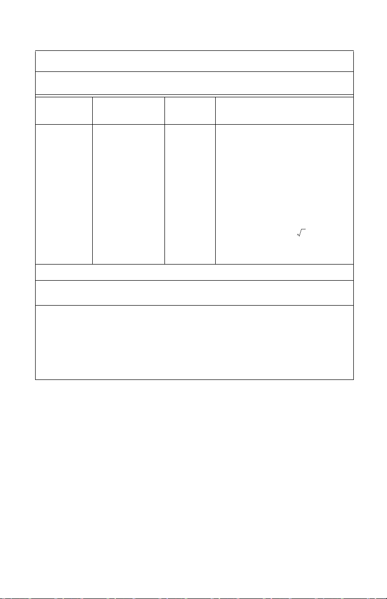
• The LCD also displays warning and error codes. The table below lists
and defines the warning and error codes displayed.
Code Definition Recommended
Action
E-1 All conditions are met for the bulb to
illuminate, yet it remains off.
E-2 All conditions are not met for the bulb
to illuminate, yet it remains on.
E-3 The bulb has higher than expected
current or voltage applied to it.
E-4 The bulb is kept off because the ballast
fan is not working properly.
E-5 The bulb is kept off because the bulb fan
is not working properly.
Blinking
500
The bulb has exceeded its
recommended lifetime of 500 hours.
Return the X8000 for
repair.
Return the X8000 for
repair.
Return the X8000 for
repair.
Return the X8000 for
repair.
Return the X8000 for
repair.
Install a new Stryker
bulb.
12
Page 15

Code Definition Recommended
Action
Replace
Bulb
The bulb has reached 1000 hours and
has exceeded its recommended lifetime
Install a new Stryker
bulb.
of 500 hours.
Language Selection
The X8000 LCD has the capability of displaying text in the following languages:
Danish German Polish
Dutch Greek Portuguese
English Italian Simplified Chinese
Finnish Japanese Spanish
French Korean Swedish
To select a particular language, perform the following steps:
1. Hold down the Up and Down buttons until the current language
identifier appears.
2. Use Mode button to scroll through the available languages.
3. Hold down the Up and Down buttons (until the light source resumes
normal operation) to lock in the selected language.
Safety Shutoff
The X8000 Light Source is equipped with a Safety Shutoff feature which will
temporarily turn off the bulb in the event of excessive heat in the bulb assembly.
W
ARNING ONCE THE LIGHT SOURCE COOLS DOWN (AFTER 7-10 MINUTES),
POWER WILL RESUME TO THE BULB AND THE UNIT WILL RESTART
IN STANDBY MODE. TO PREVENT FIRES AND ACCIDENTAL BURNS
TO THE PATIENT, USER OR INANIMATE OBJECTS, ALWAYS PLACE
THE SCOPES AND/OR FIBEROPTIC CABLES IN A SAFE PLACE, AND
NOT ON THE PATIENT, DRAPES, OR OTHER FLAMMABLE
MATERIAL, TO ENSURE SAFE RESUMPTION OF LIGHT OUTPUT. IF
THE X8000 LIGHT SOURCE EXPERIENCES A TEMPORARY
SHUTDOWN, IT IS RECOMMENDED THAT THE DEVICE BE
RETURNED FOR SERVICE.
Caution Do not abruptly interrupt power to the unit. This will turn off
the fan and may cause severe damage to the internal cooling
system.
13
Page 16

Checking the ESST Feature
The X8000 is equipped with Electronic Scope Sensing Technology (ESST), a
special safety feature that helps prevent accidental fires or burns to the patient or
user caused by a light cable not connected to a scope. This feature will only work
if the X8000 is used with an ESST light cable. When operated with an ESST light
cable, the X8000 senses when the scope and light cable are separated, and places
the light source in Standby mode. In Standby mode, the X8000 will reduce light
output to a minimum, preventing the light cable from generating excessive heat.
To verify the ESST feature is active, perform the following test before every
surgical procedure:
1. Set up the X8000 system with an ESST light cable and scope, and then
power on the system.
2. Place the X8000 in Run mode.
3. Remove the light cable from the ESST scope adapter.
The X8000 should return to Standby mode, indicating that the ESST feature is
functioning properly.
W
ARNING ALWAYS CHECK TO ENSURE THAT THE UNIT HAS SWITCHED INTO
STANDBY MODE, BEFORE ASSUMING ESST SAFETY PROTECTION. IF
THE UNIT FAILS TO RETURN TO STANDBY MODE, THERE MAY BE A
FAULT WITH THE ESST FEATURE. IN THIS CASE, DO NOT ASSUME
ESST
SAFETY PROTECTION, AND RETURN THE UNIT FOR SERVICE.
W
ARNING EVEN WITH ESST PROTECTION, OR WHEN THE X8000 IS IN
STANDBY MODE, NEVER PLACE THE TIP OF THE LIGHT CABLE OR
LIGHT CABLE ADAPTER DIRECTLY ON THE PATIENT, DRAPES OR
OTHER FLAMMABLE MATERIAL, AS BURNS OR FIRE MAY RESULT.
T
HE SCOPE TIP, SCOPE LIGHT POST, LIGHT CABLE ADAPTER, AND
LIGHT CABLE TIP WILL TAKE SEVERAL MINUTES TO COOL OFF
AFTER BEING PLACED IN STANDBY MODE, AND THEREFORE MAY
STILL RESULT IN FIRE AND/OR BURNS TO THE PATIENT, USER, OR
AN INANIMATE OBJECT IF NOT USED PROPERLY. DO NOT PLACE
THE SCOPE OR THE LIGHT CABLE ON THE PATIENT, ON THE
DRAPES, OR OTHER FLAMMABLE MATERIAL, EVEN WHEN THE
DEVICE IS IN STANDBY MODE.
14
Page 17

Using the X8000 with a Voice-Controlled System
Interface
The X8000 can be used in conjunction with Stryker voice-control systems
(SIDNE®). For more information about using the X8000 with Stryker voicecontrol systems, refer to the SIDNE® Operating and Maintenance Manual
(P/N 1000-400-653).
Using the SFB Serial Interface
The SFB serial connection on the rear panel of the X8000 enables FireWire
connection to the Stryker Endoscopy Software Management site. Connecting to
this site enables remote diagnostics and software updates.
Note This system feature is not necessary for regular light-source
operation.
Note This system feature requires an additional device (i.e., a
computer) to connect to the Software Management site.
15
Page 18

Troubleshooting
Problem Possible Solution
No light output • Ensure the AC power cord is properly connected to a
hospital-grade power outlet and the inlet on the rear
console panel.
• Ensure the power switch on the front panel is
powered on. (It will illuminate when powered on.)
• Ensure all fuses are operating. See the “Replacing the
Fuses” section of this manual for further instructions.
• Ensure the bulb is properly seated in the bulb
housing. The bulb handle should be turned all the
way to the left within the light source.
• Ensure the bulb is in operating condition. Replace the
bulb if necessary.
• Ensure the light cable is correctly engaged with the
cable port. As a safety feature, the X8000 will provide
no light output unless a fiberoptic light cable is
properly seated in the cable port.
• Ensure the bulb access door is completely shut.
• Check for error codes E-1, E-2, E-3, E-4 or E-5. See
the “Visual Display” section of this manual for details.
• Check that vents are not obstructed.
• If the safety shutoff has been activated, please return
the X8000 for service. Please see the section entitled
“Safety Shutoff” in this manual for additional
information.
16
Page 19

Too much or too
little light output
• Ensure the light cable is correctly engaged with the
cable port.
• Ensure the bulb has adequate bulb life remaining.
The bulb has a warranty of 500 hours.
• Ensure the X8000 is in Run mode. (The Run LED
should be illuminated.) If necessary, press the Mode
button to switch from Standby to Run. If the unit
remains in Standby:
1. Ensure the light cable is correctly engaged with
the cable port.
2. If an ESST cable is connected to the X8000,
ensure the cable is attached to the scope using
an ESST scope adapter.
• Use the up/down buttons to adjust the brightness. For
details, see the “Adjusting the Brightness” section in
this manual.
• Ensure the fiberoptic cable is transmitting light
properly. Hold the light-source end of the cable up to
an overhead room light and look into the scope end
of the light cable. If the pattern contains any black
spots, the light cable may be worn out and may
require replacement.
• Ensure the light cable is of an adequate size for the
application. The cable diameter may be too small to
provide adequate light transmission for the medical
video camera in the endoscopic application.
Excessive glare in
the video
• Ensure the electronic shutter on the camera is
operating properly to control the video signal
brightness. If further light reduction is required,
decrease the light source brightness with the down
button.
17
Page 20

Cleaning and Maintenance
Cleaning the X8000
WARNING UNPLUG THE X8000 BEFORE CLEANING THE UNIT.
1. Clean the external surfaces of the X8000 using a cloth or sponge
dampened with a mild detergent or disinfectant.
2. Clean and maintain the light cable according to the manufacturer’s
instructions.
Caution Do not use any abrasive cleaners. Do not allow any liquid to
drip into the unit.
Caution Do not sterilize or immerse the X8000.
Caring for the Bulb Module
The X8000 uses a Xenon bulb, which has a guaranteed life of 500 hours when
used properly. Always follow these guidelines to ensure maximum bulb life:
1. Clean the bulb face with alcohol and a cotton swab if it is touched. Dirt
or oil on the bulb face will cause the bulb to heat unevenly and fail.
2. Do not power on and off the bulb in rapid succession. Allow the bulb to
run for at least five minutes once it has been powered on. Failure to do so
can cause the bulb to rapidly darken and fail.
3. The X8000 has been designed to start the bulb under most conditions,
even when it is hot. However, if the bulb does not start within 10 seconds
after the X8000 has powered on, turn the unit off and wait at least five
minutes for the bulb to cool before restarting. Further attempts to start
the bulb can damage the bulb and possibly the internal circuitry.
Replacing the Bulb Module
Replace the bulb module when the LCD indicates 500 hours or when the bulb no
longer sufficiently illuminates the surgical site. If possible, replace the bulb
module between surgical procedures.
W
ARNING DURING OPERATION, THE BULB AND THE HOUSING AROUND THE
BULB MAY BE HOT. WAIT AT LEAST THREE MINUTES FOR THE
BULB TO COOL BEFORE HANDLING IT.
18
Page 21

To replace the bulb module:
1. Power down the X8000.
2. Open the bulb door (Figure 5).
Figure 5 Opening the bulb door
Note If the unit is on, opening the bulb door will turn off the bulb.
3. Rotate the handle to the right, grasp the bulb module by the handle, and
remove the bulb (Figure 6).
Figure 6 Removing the bulb module
WARNING DO NOT REACH INSIDE THE BULB DOOR FOR ANY REASON OTHER
THAN REPLACING THE BULB MODULE. TOUCHING PARTS OTHER
THAN THE BULB MODULE MAY CAUSE BURNS OR PRODUCT
DAMAGE.
W
ARNING DO NOT TOUCH ANY PART OF THE BULB MODULE EXCEPT FOR
THE HANDLE. THE MODULE MAY BE VERY HOT AND CAUSE
BURNS.
19
Page 22
4. Insert the new bulb module (Stryker part number 220-201-000) along
the guide rails until it is fully seated on the mating connectors.
5. Rotate the handle to the left to secure the bulb module within the light
source.
6. Close and latch the bulb door.
7. Power on the unit.
8. Power on the bulb (if not already on) and verify that the LCD displays
the bulb hours as “0”.
Note Using a non-Stryker replacement bulb module will result in no
light output.
Caution Do not operate the X8000 with a burned-out bulb or with no
bulb installed.
Replacing the Fuses
1. Unplug the light source from the AC outlet and remove the power cord
from the rear of the unit.
2. Unlatch the fuse holder and remove the fuse(s).
3. Replace the fuse(s) with fuses of the same value and rating.
W
ARNING TO HELP AVOID THE RISK OF FIRE, USE ONLY FUSES RATED AS
SPECIFIED ON THE CONSOLE.
4. Reinstall the fuse holder.
Disposing of the X8000
The device must be disposed of according to local laws and hospital practices.
The device does not contain any hazardous materials.
This product is considered electronic equipment. It must not be disposed of as
unsorted municipal waste and must be collected separately. Please contact the
manufacturer or other authorized disposal company to decommission your
equipment.
20
Page 23

Technical Specifications
Electrical
Primary: 100 - 120 VAC, 50/60 Hz, 450 W
220 - 240VAC, 50/60 Hz, 450W
Fuses (2): T 5.0 AH 250 V
Dimensions
Height: 4.75"(12.1 cm)
Width: 12.5" (31.8 cm)
Depth: 16.8" (42.7 cm)
Weight: 16.0 lbs. (7.3 kg)
Fiberoptic Cable Range:
2 mm to 6.5 mm diameter
Bulb
Type: 300 Watt Xenon (Elliptical)
Life: Approximately 500 hours
Operating Conditions
10 to 40°C
30 to 75% Relative Humidity
700hPa to 1060hPa
Transportation & Storage
-20 to 50°C
10% to 75% Relative Humidity
700hPa to 1060hPa
Classifications
Class 1 Equipment
Type CF applied par t s
Water Ingress Protection, IPX0 — Ordinary Equipment
Continuous Operation
21
Page 24
Electromagnetic Compatibility
Like other electrical medical equipment, the X8000 requires special precautions
to ensure electromagnetic compatibility with other electrical medical devices. To
ensure electromagnetic compatibility (EMC), the X8000 must be installed and
operated according to the EMC information provided in this manual.
Note The X8000 has been designed and tested to comply with IEC
60601-1-2 requirements for EMC with other devices.
Caution Portable equipment may affect the normal function of the
X8000.
W
ARNING DO NOT USE CABLES OR ACCESSORIES OTHER THAN THOSE
PROVIDED WITH THE X8000, AS THIS MAY RESULT IN INCREASED
ELECTROMAGNETIC EMISSIONS OR DECREASED IMMUNITY TO
SUCH EMISSIONS.
W
ARNING IF THE X8000 IS USED ADJACENT TO OR STACKED WITH OTHER
EQUIPMENT, OBSERVE AND VERIFY NORMAL OPERATION OF THE
X8000
IN THE CONFIGURATION IN WHICH IT WILL BE USED
PRIOR TO USING IT IN A SURGICAL PROCEDURE. CONSULT THE
TABLES BELOW FOR GUIDANCE IN PLACING THE X8000.
Guidance and Manufacturer's Declaration: Electromagnetic Emissions
X8000 is intended for use in the electromagnetic environment specified below. The customer or the
Emissions test Compliance Electromagnetic Environment - guidance
RF emissions CISPR
Harmonic emissions
IEC61000-3-2
Voltage Fluctuations/
flicker emissions
IEC61000-3-3
user of X8000 should ensure that it is used in such an environment.
11
Class B
Class A
Complies
X8000 is suitable for use in all establishments,
including domestic establishments and those
directly connected to the public low-voltage
power supply network that supplies buildings
used for domestic purposes.
22
Page 25

Guidance and Manufacturer's Declaration: Electromagnetic Immunity
X8000 is intended for use in the electromagnetic environment specified below. The customer or
Electrostatic Discharge
Electrical fast transient/
Voltage dips, short
interruptions and voltage
variations on power supply
Power frequency (50/60Hz)
NOTE: Ut is the AC mains voltage prior to application of the test level.
the user of X8000 should ensure that it is used in such an environment.
Immunity Test
(ESD)
IEC61000-4-2
burst
IEC61000-4-4
Surge
IEC61000-4-5
input lines
IEC61000-4-11
magnetic field
IEC 61000-4-8
IEC 60601 Test
Level
±6kV contact
±8kV air
±2kV for power
supply lines
±1kV for input/
output lines
±1kV differential
mode
±2kV common
mode
<5% Ut (>95% dip
in Ut) for 0.5 cycle
40% Ut (60% dip in
Ut) for 5 cycles
70% Ut (30% dip in
Ut) for 25 cycles
<5% Ut (>95% dip
in Ut) for 5 sec.
3 A/m N/A
Compliance Level
±2,4,6kV contact
±2,4,8kV air
±2kV line to ground
±1kV line to line
±0.5, 1kV
differential mode
±0.5, 1, 2kV
common mode
<5% Ut (>95% dip
in Ut) for 0.5 cycle
40% Ut (60% dip in
Ut) for 5 cycles
70% Ut (30% dip in
Ut) for 25 cycles
<5% Ut (>95% dip
in Ut) for 5 sec.
Electromagnetic
Environment:
Guidance
Floors should be
wood, concrete, or
ceramic tile. If floors
are covered with
synthetic material,
the relative humidity
should be at least
30%.
Mains power quality
should be that of a
typical commercial
or hospital
environment.
Mains power quality
should be that of a
typical commercial
or hospital
environment.
Mains power quality
should be that of a
typical commercial
or hospital
environment. If the
user of X8000
requires continued
operation during
power mains
interruptions, it is
recommended that
X8000 be powered
from an
uninterruptible
power supply or a
battery.
Power-frequency
magnetic fields
should be at levels
characteristic of a
typical location in a
typical commercial
or hospital
environment.
23
Page 26
Guidance and Manufacturer's Declaration: Electromagnetic Immunity
d1.17P=
X8000 is intended for use in the electromagnetic environment specified below. The customer or
Immunity
Test
Conducted RF
IEC 61000-4-6
NOTE 1: At 80 MHz and 800 MHz, the higher frequency range applies.
NOTE 2: These guidelines may not apply in all situations. Electromagnetic propagation is affected by
absorption and reflection from structures, objects, and people.
(a) Field strengths from fixed transmitters, such as base stations for radio (cellular/cordless)
telephones and land mobile radios, amateur radio, AM and FM radio broadcast, and TV broadcast,
cannot be predicted theoretically with accuracy. To assess the electromagnetic environment due to
fixed RF transmitters, an electromagnetic site survey should be considered. If the measured field
strength in the location in which the X8000 system is used exceeds the applicable RF compliance level
above, the X8000 system should be observed to verify normal operation. If abnormal performance is
observed, additional measures may be necessary, such as reorienting or relocating the X8000 unit.
(b) Over the frequency range 150 kHz to 80 MHz, field strengths should be less than 3 V/m.
the user of X8000 should ensure that it is used in such an environment.
IEC 60601 Test
Level
3 Vrms
150 kHz to 80 MHz
Compliance
Level
3 V
Electromagnetic Environment:
Portable and mobile RF communications
equipment should be used no closer to
any part of the X8000 system, including
its cables, than the recommended
separation distance calculated from the
equation applicable to the frequency of
Recommended Separation Distance
Guidance
the transmitter.
24
Page 27
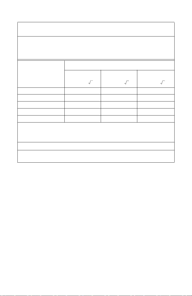
Recommended Separation Distances Between Portable and Mobile RF Communications
d1.17P=
d1.17P=
d2.33P=
The X8000 system is intended for use in an electromagnetic environment in which radiated RF
disturbances are controlled. The user of the X8000 system can help prevent electromagnetic
interference by maintaining a minimum distance between portable and mobile RF communications
equipment (transmitters) and the X8000 system as recommended below, according to the maximum
Rated maximum output
power (W) of transmitter
0.01 0.12 0.12 0.23
0.1 0.37 0.37 0.74
11.171.172.33
10 3.70 3.70 7.37
100 11.70 11.70 23.30
For transmitters rated at a maximum output power not listed above, the recommended separation
distance (d) in meters (m) can be estimated using the equation applicable to the frequency of the
transmitter, where P is the maximum output power rating of the transmitter in watts (W) according to
NOTE 1: At 80 MHz and 800 MHz, the separation distance for the higher frequency range applies.
NOTE 2: These guidelines may not apply in all situations. Electromagnetic propagation is affected by
absorption and reflection from structures, objects, and people.
Equipment and the X8000 System
output power of the communications equipment.
Separation distance (m) according to frequency of transmitter
150 kHz to 80 MHz 80 MHz to 800 MHz 800 MHz to 2.5 GHz
the transmitter manufacturer.
25
Page 28

Warranty
Stryker Endoscopy warrants the X8000 Light Source against defects in both
materials and workmanship to the registered owner at the time of purchase.
All components except the bulb are covered by the warranty for a period of one
year from the date of purchase. The bulb module is covered by the warranty for
a period of 60 days from the date of purchase.
This warranty does not apply to any unit that has been subject to misuse, abuse,
neglect, improper installation or operation, or that has been altered, adjusted, or
tampered with by any person other than Stryker Endoscopy authorized service
personnel.
The customer is responsible for returning the defective equipment to the factory
at his or her own expense. Stryker Endoscopy or its representative will service the
unit, repair or replace any defective parts thereof, and return the unit to the
customer.
If, upon examination, it is determined that the fault has been caused by misuse or
abnormal conditions of operation, the repairs will be billed to the customer in the
same manner as out-of-warranty repairs.
Instruments repaired by Stryker Endoscopy will be issued a thirty-day warranty
against defects in both materials and workmanship, provided the original
warranty period has passed. Instruments submitted due to defects in materials
and workmanship during the warranty period will be repaired at no charge to the
customer.
The warranty as set forth herein is exclusive and in lieu of all other warranties,
remedies, obligations, and liabilities of Stryker Endoscopy Inc., expressed or
implied, including the implied warranties of merchantability and fitness for use
and of consequential damages. These products are sold only for the purpose
described herein, and such warranty runs only to the purchaser. In no event shall
Stryker Endoscopy be liable for any breach of warranty in any amount exceeding
the purchase price of the product.
No agent, employee, or representative of Stryker Endoscopy has the authority to
bind the Company to any other warranty, affirmation, or representation
concerning this instrument.
This warranty is valid only to the original purchaser of Stryker Endoscopy
products obtained directly from Stryker Endoscopy or from a Stryker Endoscopy
authorized agent. The warranty cannot be transferred or assigned by the original
purchaser.
The X8000 Light Source warranty is void if any WARNINGS, CAUTIONS, or
NOTES are disregarded.
26
Page 29

Service and Claims
This equipment is carefully packaged to prevent damage during transit and is
shipped freight outbound (F.O.B.) from San Jose, CA. Therefore, Stryker’s
responsibility for ensuring damage-free delivery totalled ends upon remission of
the equipment to the carrier. Examine the shipment promptly upon receipt.
If the product packaging appears damaged at the time of delivery, immediately
check the device for damage. If there is a malfunction, return the device to the
distributor.
To return equipment damaged during shipment:
1. File a claim with both the carrier and the distributor.
2. Repack the equipment in its original shipping container and ship it
prepaid and insured to:
Stryker Endoscopy
Customer Service Department
5900 Optical Court
San Jose, CA 95138
USA
If service is needed either during or after the warranty period:
1. Contact Stryker Endoscopy at 1-800-624-4422 or phone your local
Stryker Endoscopy sales representative.
2. Package all the components carefully in the original shipping container
if possible.
3. Ship the light source, prepaid and insured to:
Stryker Endoscopy Customer Service
Attention: Repair Department
5900 Optical Court
San Jose, CA 95138
USA
Note To maximize the longevity, performance, and safety of this device,
package it in the original shipping container when storing or
transporting.
Note The light source described in this manual is continually reviewed,
and improvements may be made without notice. A replacement
part may not appear the same as the original, but all parts with the
same part number will be completely interchangeable.
27
Page 30

28
Page 31

Page 32

Stryker Endos copy
5900 Optical Court
San Jose, CA 95138 USA
1-408-754-2000, 1-800-624-4422
www.stryker.com
Stryker Corporation or its divisions or other corporate affiliated entities own, use or have applied for the following
trademarks or service marks: the Stryker logo. All other trademarks are trademarks of their respective owners.
2014/01
1000-400-885 F
 Loading...