

Page 1
APPROVALS DATE TITLE
DRAWN BY:
A. Infanger
ORIGINATOR
02/28/07
Stryker Endoscopy
5900 Optical Court, San Jose, CA 95138
X8000 Light Source
Service Guide
A. Infanger
SIZE REV. DOCUMENT NO. SHEET OF
02/28/07
A A 1000-400-933 1 71
REVISIONS REVISIONS
LTR ECN NO. DATE APPROVED LTR ECN NO. DATE APPROVED
A ECO 104650 02/28/07 A. Infanger
B
C
D
E
F
G
H
J
K
L
M
N
P
R
T
U
V
W
Y
Printing Instructions:
1. 8.5 × 11” portrait
2. Front and back
3. Color printing
4. Select binding and paper weight based on cost
Global Source:
Archive this document as a service/repair guide.
Page 2

X8000 Light Source
220-200-000
Service Guide
2007/02 www.stryker.com 1000400933 A
Page 3

Page 4

Contents
Warnings and Cautions ..................................................................................................................4
Introduction ..........................................................................................................................................5
Service Options ....................................................................................................................................5
Required Skills, Tools, and Components .............................................................................................5
Reference Documents .........................................................................................................................5
Device Description ...........................................................................................................................6
Technical Specications .......................................................................................................................6
Device Diagrams ..................................................................................................................................7
Basic Maintenance .........................................................................................................................10
Cleaning the X8000 ............................................................................................................................10
Caring for the Bulb Module ................................................................................................................10
Replacing the Bulb Module ................................................................................................................10
Replacing the Fuses ...........................................................................................................................11
Disposing of the X8000 ......................................................................................................................11
Troubleshooting ................................................................................................................................12
Error Code Denitions ........................................................................................................................13
Diagnosis ..............................................................................................................................................14
Control Board Diagrams ....................................................................................................................18
Repair/Replacement ......................................................................................................................19
1.0 Chassis Cover ..............................................................................................................................20
2.0 Control Board ...............................................................................................................................21
3.0 Ballast ..........................................................................................................................................25
4.0 Bulb Mount Board .......................................................................................................................32
5.0 AC Inlet Board .............................................................................................................................35
6.0 Jaw Handle ..................................................................................................................................38
7.0 LED power switch .......................................................................................................................39
8.0 Display Board ..............................................................................................................................43
9.0 Front Panel Membrane .................................................................................................................45
10.0 Shutter ........................................................................................................................................47
11.0 Hot Mirror ...................................................................................................................................49
12.0 Motor ..........................................................................................................................................51
13.0 Jaw Assembly ............................................................................................................................53
14.0 Integrating Rod .........................................................................................................................55
15.0 AC Inlet Filter ..............................................................................................................................57
16.0 Ballast Fan .................................................................................................................................60
17.0 Bulb Fan .....................................................................................................................................62
Final Testing and Inspection .....................................................................................................65
Tools Needed .....................................................................................................................................65
Hi-Pot/Di-Electric Breakdown Test ....................................................................................................67
Warranty ................................................................................................................................................67
3
Page 5
Warnings and Cautions
Please read this manual and follow its instructions carefully.
e words warning, caution, and note carry special
meanings and should be carefully reviewed:
Warning Warnings indicate risks to the safety
of the patient or user. Failure to follow
warnings may result in injury to the
patient or user.
4. Ensure that readjustments, modications, and/
or repairs are carried out exclusively by Stryker
Endoscopy or other authorized personnel.
5. Ensure that the electrical installation of the relevant
operating room complies with the applicable IEC,
CEC, and NEC requirements.
Federal law (United States of America) restricts this device
to use by, or on order of, a physician.
Caution Cautions indicate risks to the
equipment. Failure to follow cautions
may result in product damage.
Note Notes provide special information to
clarify instructions or present additional
useful information.
An exclamation mark within a triangle
is intended to alert the user of special
warnings or important operating and
maintenance instructions in the manual.
A lightning bolt within a triangle is
intended to warn of the presence of
hazardous voltage. Refer all service to
authorized personnel.
e incorrect use of any of the required tools and/or
techniques may risk damage to the equipment or injury to
the person carrying out the procedure, subsequent operators,
or patient. Perform the repair ONLY if you have been
specically trained in the use of all pertinent equipment
and techniques. Stryker Endoscopy cannot continue to
guarantee compliance to UL, CSA, TUV, or other labeled
safety standards if service is performed by anyone other than
Stryker Endoscopy personnel.
To help avoid potential serious injury to the user and the
patient and/or damage to this device:
1. Read this manual thoroughly, especially the
warnings, and be familiar with its contents prior to
using this equipment.
2. Never sterilize any part of the X8000 console.
3. Disconnect the X8000 from the electrical outlet
when inspecting the fuses.
IMPORTANT SAFETY NOTICE
Before operating or performing any maintenance or
repairs on the X8000 Light Source, read the user guide
and service guide thoroughly and carefully. When using
any light source, such as the X8000, re and/or severe
injury may result to the patient, user or inanimate
objects, if the instructions in this manual are not
followed.
All light sources, including the X8000, can generate
signicant amounts of heat at the scope tip, the scope
light post, the light cable tip, and/or near the light cable
adapter. Higher levels of brightness from the light source
result in higher levels of heat.
To avoid the risk of burns and/or re:
• Always adjust the brightness level of the camera
and the monitor before adjusting the brightness
level of the light source.
• Adjust the brightness level of the light source to
the minimum brightness necessary to adequately
illuminate the surgical site.
• Adjust the internal shutter of the camera higher
in order to run the light source at a lower
intensity.
• Avoid touching the scope tip or the light cable
tip to the patient, and never place them on top
of the patient, as doing so may result in burns to
the patient or user.
• Never place the scope tip, the scope light post,
the light cable adapter, or the light cable tip on
the surgical drapes or other ammable material,
as doing so may result in re.
• Always place the light source in Standby mode
whenever the scope is removed from the light
cable or the device is unattended. e scope
tip, scope light post, light cable adapter, and
light cable tip will take several minutes to cool
o aer being placed in Standby mode, and
therefore may still result in re or burns to the
patient, user, or inanimate objects.
4
Page 6

Introduction
Required Skills, Tools, and Components
is manual is intended to be used as a service guide for
Stryker repair technicians in the installation, maintenance,
and repair of the Stryker X8000 Light Source. It is meant
to be used in conjunction with the X8000 Light Source
User Manual (1000-400-885) and does not replace existing
documentation.
Service Options
Factory Service
Due to the complexity of the X8000 Light Source, Stryker
recommends that any malfunctioning system be returned
to Stryker Endoscopy for repair or replacement, where
specialized equipment and technicians are available to
perform repairs while maintaining full product quality and
safety. If service is needed either during or aer the warranty
period:
1. Contact Stryker Endoscopy at 1-800-624-4422,
or contact your local Stryker Endoscopy sales
representative.
2. Package all the components carefully in the original
shipping container, if possible.
3.
Ship the X8000 Light Source, prepaid and insured, to:
Stryker Endoscopy Customer Service
Attention: Repair Department
5900 Optical Court
San Jose, California 95138
You may request a loaner unit during the repair period.
On-Site Service
Stryker Endoscopy accepts responsibility for the eects on
safety, reliability, and performance of the equipment only if
readjustments, modications, and repairs have been carried
out exclusively by a person specically authorized by Stryker
Endoscopy to do so.
On-site repair should be carried out only by qualied
technicians with the proper test equipment listed in this
manual, so that the safety of operators and patients is not
compromised.
In no event shall Stryker Endoscopy be liable for incidental
or consequential damages in connection with or arising from
the performance or use of its products aer unauthorized
modication or repair.
e repair procedures described in this manual require a
basic set of skills, tools, and replacement components.
Skills
Stryker recommends diagnostic and repair procedures be
performed by authorized, qualied technicians with training
or experience in the following:
• Basic electronics
techniques
• Multimeter operation
• Oscilloscope operation
• Vectorscope operation
• BioTek Safety Analyzer
operation
To o l s
Most of the procedures described in this manual can be
performed using a basic tool kit that includes the items listed
below.
Basic tools Advanced tools
• Phillips screwdriver
• Flathead screwdriver
• 8˝ adjustable wrench
• Needlenose pliers
• Color video monitor
• Glass fuse puller
• Multimeter
• Oscilloscope
(20 Mhz or higher)
• NTSC/Pal Vectorscope
• BioTek Model 601
PRO Safety Analyzer
or equivalent current
leakage tester
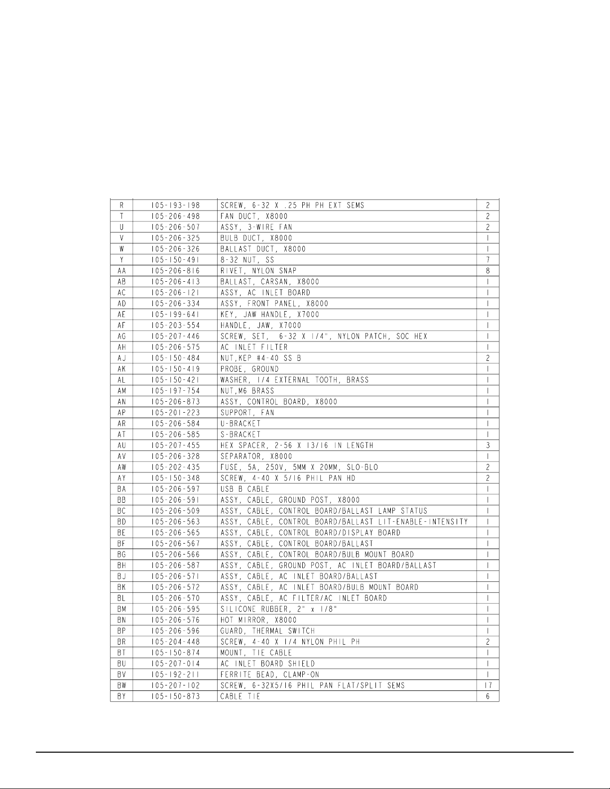
Components
Replacement parts are identied in the “Device Diagrams”
section of this manual. Certain components are for in-house
use only and will not be available to any non-Stryker entity.
Before any parts are purchased, an Indemnication Letter
must be signed and submitted to Stryker Endoscopy,
available from Customer Service at 1-800-624-4422.
Stryker reserves the right to incorporate improvements
to the X8000 without notice and will inform customers of
any signicant upgrades. All updated parts will be fully
interchangeable with older versions and will oer at least the
same level of quality and performance.
For up-to-date information on upgrades to the product or to
this manual, contact your Stryker representative.
Reference Documents
None of the in-house Manufacturing Assembly Procedures
(MAPs), Quality Inspection Procedures (QIPs), specialty
tools, jigs, or xtures listed in this manual are available for
purchase.
5
Page 7

Device Description
Technical Specifications
e Stryker X8000 Light Source is a light-generating unit
designed to illuminate surgical sites during endoscopic
applications. e X8000 uses a 300-watt xenon bulb to
generate light, which it delivers to the surgical site via a
beroptic light cable.
e X8000 is compatible with all Stryker light cables, and,
with the proper light cable and adapters, can connect to any
exible or rigid endoscope.
e X8000 is equipped with Electronic Scope Sensing
Technology (ESST), a special safety feature that helps
prevent accidental burns caused by a light cable that is
not connected to the scope. When operated with an ESST
light cable, the X8000 senses when the scope and the light
cable are separated and places the light source in Standby
mode. In Standby mode, the X8000 will reduce light output
to a minimum, preventing the light cable from generating
excessive heat.
Electrical
Primary: 100 – 120 VAC, 50/60 Hz, 450 W
220 – 240VAC, 50/60 Hz, 450 W
Fuses (2): 5.0A, 250V
Dimensions
Height: 4.75˝ (12.1 cm)
Width: 12.5˝ (31.8 cm)
Depth: 16.8˝ (42.7 cm)
Weight: 16.0 lbs (7.3 kg)
Fiberoptic Cable Range
2 – 6.5 mm diameter
Bulb
Type: 300 Watt Xenon (Elliptical)
Life: Approximately 500 hours
Operating Conditions
10 – 40°C
30 – 75% Relative Humidity
Transportation and Storage
-20 – 50°C
10 – 75% Relative Humidity
700 – 1060 hPa
Classications and Approvals
Complies with medical safety standards:
• IEC 60601-1:2005
• CAN/CSA C22.2 No.601.1-M90
• UL 60601-1: 2003
Complies with medical EMC standard:
• IEC 60601-1-2:2001
Class 1 Equipment
Type CF applied parts
Water Ingress Protection, IPX0 — Ordinary
Equipment
Continuous Operation
Patent Protection
U.S. #5,850,496; 6,110,107; and 6,689,050.
Other patents pending.
6
Page 8
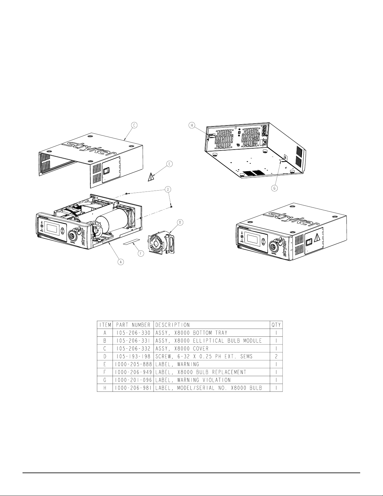
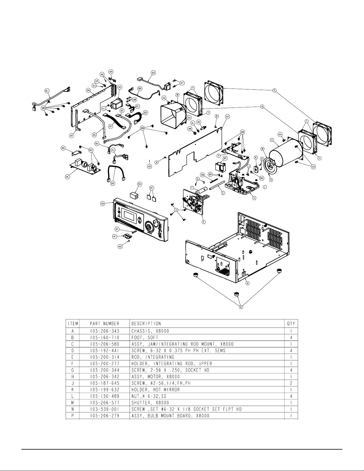
Device Diagrams
e individual components of the X8000, which are referred to throughout this manual, are identied in the
following diagrams.
To p Chassis Assembly
7
Page 9
Bottom Chassis Assembly
8
Page 10
9
Page 11
Basic Maintenance
Replacing the Bulb Module
Cleaning the X8000
Caution Unplug the X8000 before cleaning the
unit.
1. As needed, clean the external surfaces of the X8000
using a cloth or sponge dampened with a mild
detergent or disinfectant.
2. Clean and maintain the light cable according to the
manufacturer’s instructions.
Caution Do not use any abrasive cleaners. Do not
allow any liquid to drip into the unit.
Caution Do not sterilize or immerse the X8000.
Caring for the Bulb Module
e X8000 uses a Xenon bulb, which has a guaranteed
life of 500 hours when used properly. Always follow these
guidelines to ensure maximum bulb life:
1. If the bulb is touched, clean the bulb face with
alcohol and a cotton swab. Dirt or oil on the bulb
face will cause the bulb to heat unevenly and fail.
2. Do not power on and o the bulb in rapid
succession. Allow the bulb to run for at least ve
minutes once it has been powered on. Failure to do
so can cause the bulb to rapidly darken and fail.
Replace the bulb module when the LCD indicates 500 hours
or when the bulb no longer suciently illuminates the
surgical site. If possible, replace the bulb module between
surgical procedures.
Warning During operation, the bulb and the
housing around the bulb may be hot.
Wa it at least three minutes for the bulb
to cool before handling it.
To replace the bulb module,
1. Power down the X8000 and wait at least three
minutes for the bulb to cool.
2. Open the bulb door.
3. Rotate the bulb module handle to the right, grasp it,
and withdraw the bulb.
Warning Do not reach inside the bulb door for
any reason other than replacing the bulb
module. Touching parts other than the
bulb module may cause burns or product
damage.
Warning Do not touch any part of the bulb module
except for the handle. e module may be
very hot and cause burns.
Caution e X8000 has been designed to start the
bulb under most conditions, even when
it is hot. However, if the bulb does not
start within 10 seconds aer the X8000
has powered on, turn the unit o and
wait at least ve minutes for the bulb to
cool before restarting. Further attempts
to start the bulb can damage the bulb and
possibly the internal circuitry.
10
4. Insert the new bulb module (Stryker part number
220-201-000) along the guide rails until it is fully
seated on the mating connectors.
5. Rotate the handle to the le to secure the bulb
module within the light source.
6. Close and latch the bulb door.
7. Power on the unit.
8. Power on the bulb (if not already on) and verify that
the LCD displays the bulb hours as “0.”
Note Using a non-Stryker replacement bulb
module will result in no light output.
Caution Do not operate the X8000 with a burned-
out bulb or with no bulb installed.
Page 12
Replacing the Fuses
1. Unplug the light source from the AC outlet and
remove the power cord from the rear of the unit.
2. Unlatch the fuse holder and remove the fuse(s).
3. Replace the fuse(s) with fuse(s) of the same
value and rating.
Warning To help avoid the risk of re, use only
5.0A 250V fuses.
4. Reinstall the fuse holder.
Disposing of the X8000
is product is considered electronic
equipment. It must not be disposed of
as unsorted municipal waste and must
be collected separately. Please contact
the manufacturer or other authorized
disposal company to decommission
your equipment.
11
Page 13

Troubleshooting
Problem Possible Solution
No light output
• Ensure the AC power cord is properly connected to a hospital-grade power outlet and
the inlet on the rear console panel.
• Ensure the power switch on the front panel is powered on. (It will illuminate when
powered on.)
• Ensure all fuses are operating.
• Ensure the bulb is properly seated in the bulb housing. e bulb handle should be
turned all the way to the le within the light source.
• Ensure the bulb is in operating condition. Replace the bulb if necessary.
• Ensure the light cable is correctly engaged with the cable port. As a safety feature, the
X8000 will provide no light output unless a beroptic light cable is properly seated in
the cable port.
• Ensure the bulb access door is completely shut.
• Check for error codes E-1, E-2, E-3, E-4 or E-5. See the Error Code Denitions section
of this manual for details.
• Check that vents are not obstructed.
• If the safety shuto has been activated, please return the X8000 for service. Please see
the Component Replacement section of this manual for additional information.
To o much or too little
light output
Excessive glare in the
video
• Ensure the light cable is correctly engaged with the cable port.
• Ensure the bulb has adequate bulb life remaining. e bulb has a warranty of 500 hours.
• Ensure the X8000 is in Run mode. (e Run LED should be illuminated.) If necessary,
press the Mode button to switch from Standby to Run. If the unit remains in Standby:
1. Ensure the light cable is correctly engaged with the cable port.
2. If an ESST cable is connected to the X8000, ensure the cable is attached to the scope
using an ESST scope adapter.
• Use the up/down buttons to adjust the brightness.
• Ensure the beroptic cable is transmitting light properly. Hold the light-source end of
the cable to an overhead room light and look into the scope end of the light cable. If
the pattern contains any black spots, the light cable may be worn out and may require
replacement.
• Ensure the light cable is of an adequate size for the application. e cable diameter may
be too small to provide adequate light transmission for the medical video camera in the
endoscopic application.
• Ensure the electronic shutter on the camera is operating properly to control the video
signal brightness. If further light reduction is required, decrease the light source
brightness with the down button.
12
Page 14

Error Code Definitions
e X8000 displays error codes when one of the following conditions occurs. Follow the recommended action to correct the
error.
Code Definition Recommended Action
E-1
E-2
E-3
E-4
E-5
Blinking
500
All conditions are met for the bulb to illuminate, yet it
remains o.
All conditions are not met for the bulb to illuminate, yet it
remains on.
e bulb has higher than expected current or voltage
applied to it.
e bulb is kept o because the ballast fan is not working
properly.
e bulb is kept o because the bulb fan is not working
properly.
e bulb has exceeded its recommended lifetime of 500
hours.
Consult the Diagnosis section of this manual.
Consult the Diagnosis section of this manual.
Consult the Diagnosis section of this manual.
Consult the Diagnosis section of this manual.
Consult the Diagnosis section of this manual.
Install a new Stryker bulb.
Replace
Bulb
e bulb has reached 1000 hours and has exceeded its
recommended lifetime of 500 hours.
Install a new Stryker bulb.
13
Page 15

Diagnosis
To diagnose system errors, follow the strategies provided
below. For steps that involve test points on the control
board, refer to the control board diagram at the end of the
Diagnosis section.
Diagnosis strategies are grouped by symptom:
A. Bulb does not turn on
B. Bulb does not turn o
C. Bulb ignites immediately upon system startup
D. LCD display is blue or completely dark
E. Fan does not run
F. Light source does not switch from STANDBY to
RUN mode
G. Brightness cannot be adjusted
H. E-1 error appears on the LCD display
I. E-2 error appears on the LCD display
J. E-3 error appears on the LCD display
K. E-4 error appears on the LCD display
L. E-5 error appears on the LCD display
M. Bulb hours value does not display
N. Shutter makes noise or does not move properly.
A. Bulb does not turn on
1. Check the voltages on the control board test points
TP22 and TP23.
• If the test points read 12V and 0V respectively,
then the ballast is faulty. Replace the ballast.
• If the voltages are in the vicinity of 5.5V and
7V respectively, proceed to step 2.
2. Visually check if the bulb door is properly
closed with the cover or a stand-alone magnet. If
necessary, close the door.
3. Visually check if the light cable is properly inserted
into the jaw. If necessary, reinsert the cable.
4. Visually check if the bulb has the one-wire memory
chip. If it does, ensure the chip makes contact with
the bulb mount board connector. If necessary,
adjust contact between the chip and the connector.
5. Using a multimeter, electronically check the
following test points on the control board. Each test
point should read 3.3 volts.
• PD1—reads 3.3 volts if the one wire chip is
detected by the control board. If PD1 reads 0
volts (and PD2 reads 3.3 volts), try a dierent
bulb. Push the bulb rmly towards the plastic
separator panel to ensure contact.
• PD2—reads 3.3 volts if the door reed switches
are closed. If PD2 reads 0 volts,
- Check if the reed switches on the bulb
mount boards are soldered properly. If
necessary, repair the soldering.
- Check for shorts using the magnet on the
reed switch. Repair/replace as necessary.
- Check if the cable wire colors are
correctly oriented. Adjust as necessary.
• PD3—reads 3.3 volts if the fans are functioning
properly
• PD4—reads 3.3 volts if a regular light cable is
inserted. If PD4 reads 0 volts, remove the front
panel and check if the beam sensor is properly
positioned and connected to the display board.
Adjust as necessary.
• PD5—reads 3.3 volts if an ESST light cable is
inserted. If PD5 reads 0 volts, remove the front
panel and check if the beam sensor is properly
positioned and connected to the display board.
Adjust as necessary.
6. If none of these help, contact Technical Support at
+1.800.624.4422.
B. Bulb does not turn o
If the bulb turns on immediately aer AC power is applied
to the light source, proceed to diagnosis strategy C, “Bulb
ignites immediately upon system startup.”
If the bulb ignites aer the regular startup sequence but then
will not turn o, perform the following steps until the source
of the problem is identied.
1. Remove the light cable from the jaw.
2. Open the bulb door or remove the magnet from the
reed switches.
3. Using a multimeter, check the following test points
on the control board:
• PD2—If PD2 reads 3.3 volts, the reed switches
are faulty. Replace the reed switches.
• PD4 and PD5—If either PD4 or PD5 reads 3.3
volts, the light cable sensor (beam sensor) is
faulty. Replace the light cable sensor.
4. If PD4 or PD5 reads 0 volts, measure the voltage
dierence between TP22 and TP23.
• If the voltage dierence is around -1.3 volts,
replace the ballast.
• If the voltage dierence is around 12 volts,
proceed to step 5.
5. Measure the voltage level for TP32.
• If TP32 reads 0 volts, replace the control board.
(See the Repair/Replacement Procedures
section of this manual.)
• If TP32 reads 3.3 volts, proceed to step 6.
14
Page 16

6. Measure the voltage for TP34.
• If TP34 reads 0 or 1.6 volts, replace the control board.
(See the Repair/Replacement section of this
manual.)
• If TP34 reads otherwise, contact Technical
Support at +1.800.624.4422.
C. Bulb ignites immediately upon system
startup
1. Check if the jumpers on the ballast (JP300) are
properly installed. When the ballast is viewed from
the bulb side, the jumpers should read 0 I I 0 I 0 0.
Adjust as necessary.
2. Check the voltage dierence between TP22 and
TP23 on the control board:
• Turn o system power
• Connect the positive multimeter probe to TP22
and the negative probe to TP23
• Turn on system power
• If the voltage dierence is around 12V, proceed
to step 3
• If the voltage dierence is around -1.3 volts,
replace the ballast (See the Repair/Replacement
section of this manual.).
3. Check the voltage of TP32. If it does not read 3.3
volts, replace the control board (See the Repair/
Replacement section of this manual.).
4. Make sure that the 6-pin power cable from the
ballast to the control board is connected.
• If the power button lights up, perform steps
1 – 3.
• If the power button still does not light up,
replace the control board (See the Repair/
Replacement section of this manual.).
E. Fan does not run
1. If one or both fans are not working, an E-4 (ballast)
or E-5 (bulb) error should display on the LCD
screen. Conrm this.
2. If both fans do not work, measure the voltage on the
10.2V test point on the control board (underneath
lamp status connector).
• If it does not read around 10.2 volts, replace
the control board (See the Repair/Replacement
section of this manual.).
3. If only one fan works, switch the fan connectors
between the working and non-working fans.
• If non-working fan still fails to run, then it is
faulty. Replace it. (See the Repair/Replacement
section of this manual.)
• If the non-working fan begins to run, but the
working fan stops running, then the control
board is faulty. Replace it. (See the Repair/
Replacement section of this manual.).
D. LCD display is blue or completely dark
Power on the light source:
• If you hear the fans running, or if the power
button is lighted, perform steps 1 – 3.
• If you don’t hear the fans running, and the
power button is not lighted, perform step 4.
1. Check if the cable between the control board and
front display board is connected properly. Adjust as
necessary.
2. Insert the bulb, close the bulb door, and measure the
voltages of PD1 and PD2 on the control board.
• If they do not read 3.3 volts, replace the control
board. (See the Repair/Replacement section of
this manual.)
• If they do read 3.3 volts, proceed to step 3.
3. Measure the voltage across the C47 and C48
capacitors (directly beneath the display board cable
on the control board side).
• If they read 3.3 volts and 12.3 volts respectively,
replace the display board (See the Repair/
Replacement section of this manual.).
• If not, replace the control board (See the
Repair/Replacement section of this manual.).
F. Light source does not switch from
STANDBY to RUN mode
1. Check if the bulb is lit. If it is lit, go to step 2. If it is
not lit, then go to diagnosis strategy A.
2. Press the brightness up and brightness down buttons
on the membrane. Check if the mini brightness
meter in the top right corner of the display increases
or not.
• If the meter does not change, remove the front
panel and check if the front panel membrane
connector is fully connected to the display
board. Adjust as necessary.
• If the meter does change and the membrane
is properly connected, cycle the light source
power.
- As the LCD powers up, check the soware
version numbers. ey should read at
least SW REV P 1. 2 and SW REV P.1.2
consecutively. (e revision numbers may
be higher if newer soware versions are
installed.)
- If the version numbers are not at least
1.2, contact Technical Support at
+1.800.624.4422 for soware updates.
- If the version numbers are adequate,
contact Technical Support.
15
Page 17

G. Brightness cannot be adjusted
1. Switch the light source between STANDBY and
RUN modes by pressing on the membrane switch.
(Make sure to use a non-ESST cable, or an ESST
cable that has the ESST adaptor at the tip.)
• If the light source does not switch between
modes, replace the control board (See the
Repair/Replacement section of this manual.)
• If the light source switches between modes, but
brightness cannot be increased or decreased,
proceed to step 2.
2. Remove the jaw handle and the plastic front panel.
Ensure that the front panel membrane is properly
connected to the front LCD display board. Adjust as
necessary.
3. If the membrane is properly connected, but
brightness still cannot be adjusted, replace the
membrane.
4. If the new membrane does not work, check for
proper connection between the control board and
the display board. Adjust as necessary.
5. If the membrane works aer checking the
connections, replace the front LCD display board
(See the Repair/Replacement section of this
manual.)
H. E-1 error appears on the LCD display
1. Make sure that the light cable is inserted, the bulb
door is closed with a bulb inside, and the lamp is
not lit.
2. Check the voltages on TP22 and TP23.
• If the voltage dierence between TP22 and
TP23 is not 12V, replace the control board.
• If the voltage dierence between these two test
points is 12V, ensure the J3 cable is connected
properly to the ballast and that the individual
wires are not crossed.
- Ensure that L3 and L4 ferrites, located
underneath the J3 connector, are
soldered properly to the control board.
- If these ferrites are missing, broken, or
not soldered properly, repair or replace
the control board.
3. If none of the above steps resolves the problem,
replace the ballast.
I. E-2 error appears on the LCD display
1. Make sure that the bulb is lit and the light is on.
2. Repeat diagnosis strategies B and C, respectively.
J. E-3 error appears on the LCD display
1. Probe TP13 with a multimeter.
• If it reads 3.3 volts, and E-3 still appears on the
display, replace the control board.
• If the voltage on TP13 is low, replace the
ballast.
K. E-4 error appears on the LCD display
1. Verify that the ballast fan is not running.
2. Ensure the ballast fan is connected to the control
board.
3. If the fan seems to be working, visually compare the
speed of the ballast fan to the bulb fan.
• If the ballast fan seems to be running slower,
replace the fan and verify that the E-4 error
disappears.
• If the E-4 error does not disappear with the
new fan, replace the control board.
L. E-5 error appears on the LCD display
1. Check to verify that the bulb fan is not running.
2. Ensure the ballast fan is connected to the control
board.
3. If the fan seems to be working, visually compare the
speed of the bulb fan to the ballast fan.
• If the ballast fan seems to be running slower,
replace the fan and verify that the E-5 error
disappears.
• If the E-5 error does not disappear with the
new fan, replace the control board.
M. Bulb Hours value does not display
1. Connect a regular light cable to the light source.
2. Make sure there is a bulb in the light source, close
the door, and verify that it is lit.
3. Verify that there is a one-wire memory properly
attached.
4. Verify that the one-wire memory is making contact
with the connectors on the bulb mount board.
5. If the bulb does not light, perform diagnosis
strategy A.
6. If you are unsure about the proper contact, insert a
new bulb to see if the hours will display.
7. If the hours still do not display, verify that the cable
between the bulb mount board and the control
board is properly connected.
8. If the cables are properly connected, but the hours
still do not display, replace the control board.
16
Page 18

N. Shutter makes noise or does not move
properly.
1. Check the pinouts of the motor cable and the bulb
mount board/control board cable. Make sure the
wire colors match the drawing.
2. Make sure the connectors J1 and J2 on the bulb
mount board are not soldered in the wrong
direction.
3. Make sure the minimum shutter switch is soldered
properly. Make sure the switch lever is properly
connected to the switch itself.
4. Make sure the shutter wheel is properly connected
to the motor sha.
5. Make sure the shutter wheel is not rubbing against
the hot mirror holder.
6. If the motor is rotating the shutter in the reverse
direction when power is applied to the light source,
replace the motor.
7. If the motor is hesitantly rotating the shutter back
and forward, then replace the motor.
8. If the shutter’s mini tab is catching the bottom
of the minimum shutter switch, replace the bulb
mount board.
9. If none of the steps above solves the problem,
contact Technical Support at +1.800.624.4422.
17
Page 19
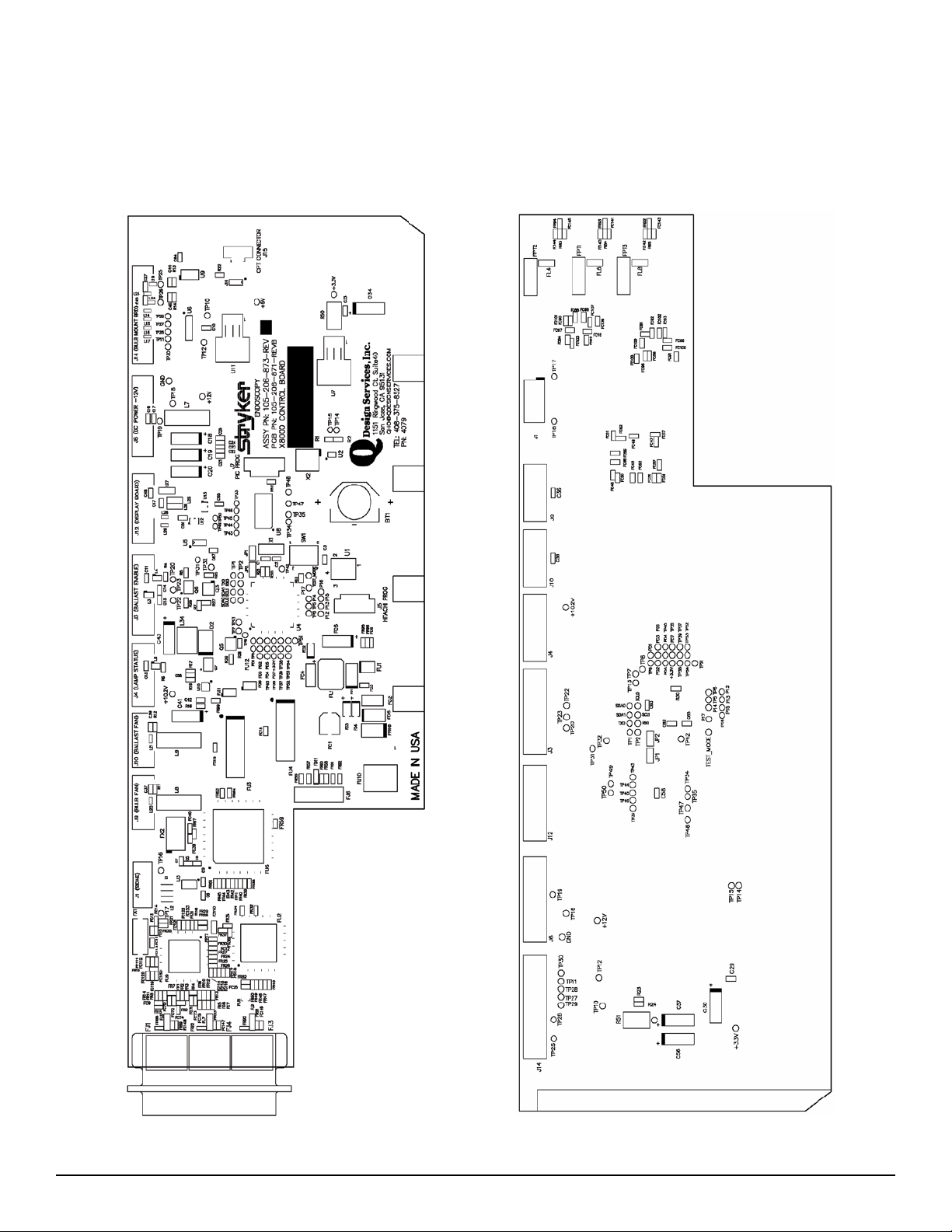
Control Board Diagrams
18
Page 20
Repair/Replacement
e X8000 Light Source is a precision instrument that has
been engineered and manufactured with great care to ensure
the safety of operators and patients. In order to maintain the
high level of safety and reliability required in devices of this
nature, it is important to fully understand and comply with
all required procedures set forth herein.
If some part of a procedure is omitted or adequate equipment
is not used, the safety and performance of the devices may
be unknowingly compromised. If any of the procedures
described in this manual are beyond the scope of the
technician’s training, consult the “Service Options” section of
this manual for information on how to obtain service from
Stryker Endoscopy.
As is the case with all AC powered
devices, dangerous voltages are present.
If adequate safety precautions are not
taken, results may include damage to the
equipment, personal injury, or death. It
is imperative that these procedures are
approached only by trained technicians
with proper equipment aer fully reading
and understanding the steps involved.
Note For all steps that involve the application of
Loctite, apply Loctite to the threaded holes
rather than to the threads on the screws
unless otherwise specied.
Note When using a power screwdriver, set
torque setting to 3 high unless otherwise
specied.
Each of the following tables provides repair/replacement
instructions for specic components of the X8000. For each
instruction, the required tools, equipment, and replacement
part numbers are provided.
Caution ESD Protection is required to perform
this assembly. Failure to follow this
procedure can cause undetectable
damage to electrical components.
19
Page 21
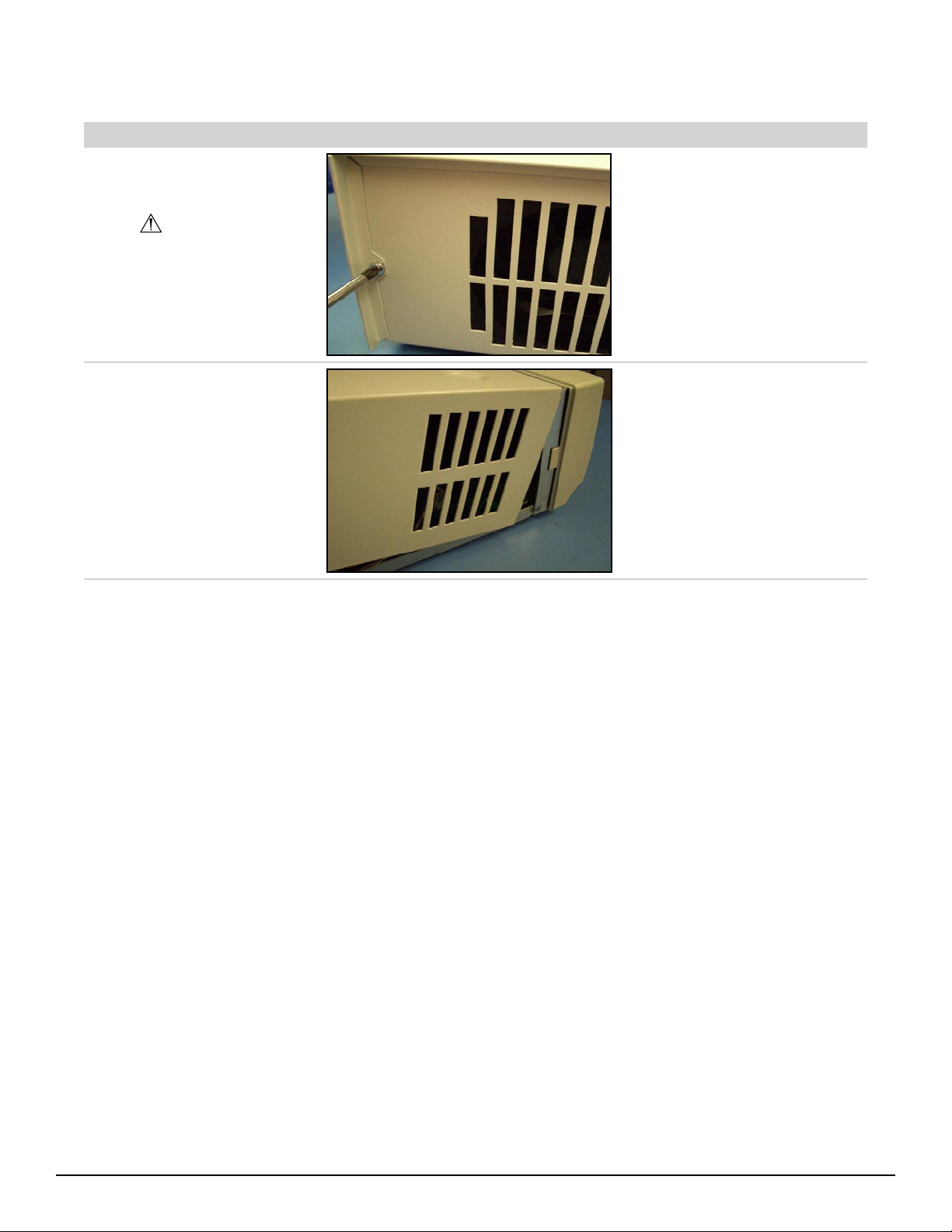
1.0 Chassis Cover
Seq. Ta s k Description Figure To o l s Needed Parts
10 Unscrew Chassis Cover
from Chassis.
Torque setting of 5.
• Power
Screwdriver
(Phillips)
• 6-32 x 0.25 PH
• X8000 Cover
• X8000 Chassis
Ext. Sems. (2)
(198)
(407)
(343)
20 Remove Chassis Cover
from Chassis.
• X8000 Cover
(407)
• X8000 Chassis
(343)
20
Page 22
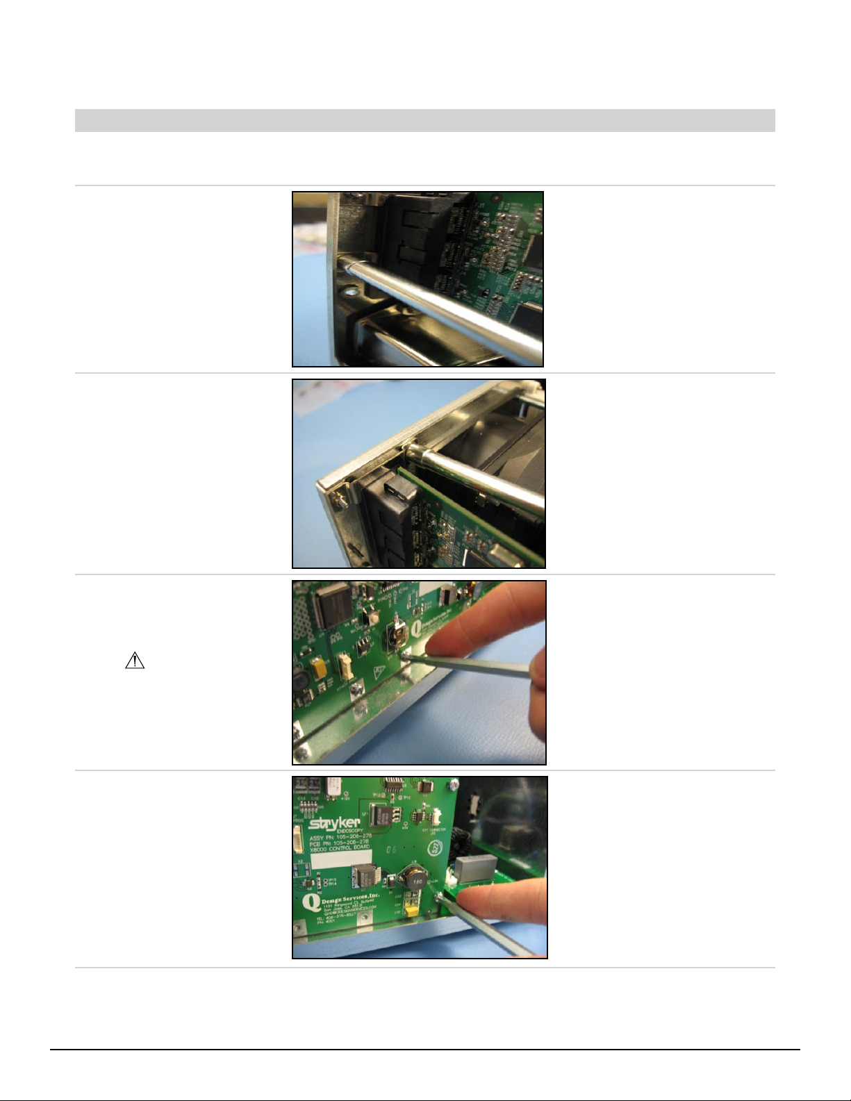
2.0 Control Board
Seq. Ta s k Description Figure To o l s Needed Parts
30 Remove Chassis Cover
from Chassis (procedure
1.0).
40 Remove all Cables
connected to the Control
Board. Unscrew S-Bracket
from Chassis as shown.
• 4mm Nut
Driver
• 2-56 Hex Nut
• S-Bracket
• X8000 Chassis
(866)
(585)
(343)
50 Unscrew U-Bracket from
Chassis as shown.
60 Unscrew Control Board
from lower Control Board
mounts as shown.
Do not bend Control
Board!
70 Unscrew Control Board
from Fan Support. Remove
Control Board from Unit.
• 4mm Nut
Driver
• Power
Screwdriver
(Phillips)
• Power
Screwdriver
(Phillips)
• 2-56 Hex Nut
(2) (866)
• U-Bracket
(584)
• X8000 Chassis
(343)
• 6-32 x 5/16
PH Screw (4)
(102)
• X8000 Control
Board (873)
• X8000 Chassis
(343)
• 6-32 x 5/16
PH Screw (2)
(102)
• Fan Support
(223)
• X8000 Control
Board (873)
21
Page 23

80 Get New Control Board.
Remove Control Board
from metal-shielded bag
and place on ESD-safe Mat.
• X8000 Control
Board (873)
90 Loosen the Fan Support
from the Chassis. is will
allow for easier reassembly.
100 Place new Control Board
into Chassis and align with
screw mounts on Chassis
ange.
Be careful not to hit the
A/C Inlet Board!
• 5/16” Nut
Driver
• 6-32 SS Nut
(489)
• Fan Support
(223)
• X8000 Chassis
(343)
• X8000 Control
Board (873)
• X8000 Chassis
(343)
110 Connect 3-Wire Fan cable
from Bulb Fan to Control
Board connector J9 (BULB
FAN).
Do not bend Control
Board!
22
• 3-Wire Fan
Cable from
Bulb Fan (3Pin 3-Wire)
• X8000 Control
Board (873)
Page 24

120 Connect 3-Wire Fan from
Ballast Fan to Control
Board connector J10
(BALLAST FAN).
Do not bend Control
Board!
• 3-Wire Fan
Cable from
Ballast Fan (3Pin 3-Wire)
• X8000 Control
Board (873)
130 Connect 4-Pin 4-Wire
Control Board/Ballast
Lamp Status Cable to
Control Board connector J4
(BALLAST FAN).
Do not bend Control
Board!
140 Connect 6-Pin 4-Wire
Control Board/Ballast LitEnable-Intensity Cable to
Control Board connector J3
(BALLAST ENABLE).
Do not bend Control
Board!
• Control
Board/Ballast
Lamp Status
Cable (4-Pin
4-Wire) (509)
• X8000 Control
Board (873)
• Control
Board/Ballast
Lit-EnableIntensity Cable
(6-Pin 4-Wire)
(563)
• X8000 Control
Board (873)
150 Connect 5-Pin 5-Wire
Control Board/Display
Board Cable from Display
Board to Control Board
connector J12 (DISPLAY
BOARD).
Do not bend Control
Board!
• Control
Board/Display
Board Cable
(5-Pin 5-Wire)
(565)
• X8000 Control
Board (873)
23
Page 25

160 Connect 6-Pin 6-Wire
Control Board/Ballast
Cable from Ballast to
Control Board connector J6
(DC POWER – 12V).
Do not bend Control
Board!
• Control
Board/Ballast
Cable (6-Pin
6-Wire) (567)
• X8000 Control
Board (873)
170 Connect 8-Pin 8-Wire
Control Board/Bulb Mount
Board Cable from Bulb
Mount Board to Control
Board connector J14 (BULB
MOUNT BRD).
Do not bend Control
Board!
180 Slide Chassis Cover onto
Chassis until ush with
Chassis and secure
190 Screw Chassis Cover to
Chassis.
Torque setting of 5.
• Power
Screwdriver
(Phillips)
• Control
Board/Bulb
Mount Board
Cable (8-Pin
8-Wire) (566)
• X8000 Control
Board (873)
• X8000 Cover
(407)
• X8000 Chassis
(343)
• 6-32 x 0.25 PH
Ext. Sems. (2)
(198)
• X8000 Cover
(407)
• X8000 Chassis
(343)
24
Page 26

3.0 Ballast
Seq. Ta s k Description Figure To o l s Needed Parts
200 Remove Chassis Cover
from Chassis (procedure
1.0).
210 Disconnect all cables on the
Control Board side.
Do not bend Control
Board!
• X8000 Control
Board (873)
220 Remove green Ground Post
A/C Inlet Board/Ballast
Cable from bottom Ballast
connector GND J103.
230 Unscrew black Ballast/
Bulb Cathode Cable from
Ballast.
240 Unscrew red Ballast/Bulb
Anode Cable from Ballast.
• Needlenose
Pliers
• Power
Screwdriver
(Phillips)
• Power
Screwdriver
(Phillips)
• Ground Post
AC Inlet
Board/Ballast
Cable (587)
• X8000 Ballast
(413)
• Ballast/Bulb
Anode Cable
Assembly
(568)
• X8000 Ballast
(413)
• Ballast/Bulb
Anode Cable
Assembly
(569)
• X8000 Ballast
(413)
25
Page 27

250 Unscrew Ballast from front-
le Chassis PEM as shown.
• Power
Screwdriver
(Phillips)
• 6-32 x 5/16
PH Screw (1)
(102)
• X8000 Ballast
(413)
• X8000 Chassis
(313)
260 Unscrew Ballast from
front-right Chassis PEM as
shown.
270 Unscrew Ballast from rear-
le Chassis PEM as shown.
280 Unscrew Ballast from
rear-right Chassis PEM as
shown
Remove the ballast from
the unit.
• Power
Screwdriver
(Phillips)
• Power
Screwdriver
(Phillips)
• Power
Screwdriver
(Phillips)
• 6-32 x 5/16
PH Screw (1)
(102)
• X8000 Ballast
(413)
• X8000 Chassis
(313)
• 6-32 x 5/16
PH Screw (1)
(102)
• X8000 Ballast
(413)
• X8000 Chassis
(313)
• 6-32 x 5/16
PH Screw (1)
(102)
• X8000 Ballast
(413)
• X8000 Chassis
(343)
26
Page 28

290 Remove Brown and Blue
lead of AC Inlet Board/
Ballast Cable from original
Ballast.
• Needlenose
Pliers
• X8000 Ballast
(413)
• A/C Inlet
Board/
Ballast Cable
Assembly
(571)
300 Remove Control Board/
Ballast Lamp Status Cable
from original Ballast.
310 Remove Control Board/
Ballast Lit-Enable-Intensity
Cable from original Ballast.
320 Get New Ballast. Remove
the Ballast from metalshielded bag and place on
ESD safe mat.
• X8000 Ballast
(413)
• Control
Board/
Ballast Lamp
Status Cable
Assembly (4Pin) (509)
• X8000 Ballast
(413)
• Control
Board/Ballast
Lit-EnableIntensity Cable
(6-Pin 4-Wire)
(563)
• X8000 Ballast
(413)
27
Page 29

330 Attach Control Board/
Ballast Cable -567 to Ballast
Connector J422.
• X8000 Ballast
(413)
• Control
Board/
Ballast Cable
Assembly
(6-Pin 6-Wire)
(567)
340 Attach Control Board/
Ballast Lit-Enable-Intensity
Cable -563 to Ballast
Connector J500.
350 Attach Control Board/
Ballast Lamp Status Cable
-509 to Ballast Connector
J504.
360 Attach Blue lead of AC Inlet
Board/Ballast Cable -571 to
top Ballast connector HOT
J101.
Flat end of connector
should face in towards
Ballast.
• Needlenose
Pliers
• X8000 Ballast
(413)
• Control
Board/Ballast
Lit-EnableIntensity Cable
(6-Pin 4-Wire)
(563)
• X8000 Ballast
(413)
• Control
Board/
Ballast Lamp
Status Cable
Assembly (4Pin) (509)
• X8000 Ballast
(413)
• A/C Inlet
Board/
Ballast Cable
Assembly
(571)
28
Page 30

370 Attach Brown lead of AC
Inlet Board/Ballast Cable
-571 to middle Ballast
connector NEUT J102 on
Ballast.
Flat end of connector
should face in towards
Ballast.
• Needlenose
Pliers
• X8000 Ballast
(413)
• A/C Inlet
Board/
Ballast Cable
Assembly
(571)
380 Place and align Ballast onto
Chassis PEM’s with Heat
Sink towards outside of
Chassis.
390 Screw Ballast to rear-right
Chassis PEM as shown.
• Power
Screwdriver
(Phillips)
• X8000 Ballast
(413)
• X8000 Chassis
(343)
• 6-32 x 5/16
PH Screw (1)
(102)
• X8000 Ballast
(413)
• X8000 Chassis
(343)
400 Screw Ballast to rear-le
Chassis PEM as shown.
• Power
Screwdriver
(Phillips)
• 6-32 x 5/16
PH Screw (1)
(102)
• X8000 Ballast
(413)
• X8000 Chassis
(313)
29
Page 31

410 Screw Ballast to front-right
Chassis PEM as shown.
• Power
Screwdriver
(Phillips)
• 6-32 x 5/16
PH Screw (1)
(102)
• X8000 Ballast
(413)
• X8000 Chassis
(313)
420 Screw Ballast to front-le
Chassis PEM as shown.
430 Attach green Ground Post
A/C Inlet Board/Ballast
Cable to bottom Ballast
connector GND J103.
Flat end of connector
should face in towards
Ballast.
440 Screw red Ballast/Bulb
Anode Cable from forward
Banana Plug to Ballast
connector J602 LAMP +
Screw Cable at side
down.
• Power
Screwdriver
(Phillips)
• Needlenose
Pliers
• Power
Screwdriver
(Phillips)
• 6-32 x 5/16
PH Screw (1)
(102)
• X8000 Ballast
(413)
• X8000 Chassis
(313)
• Ground Post
AC Inlet
Board/Ballast
Cable (587)
• X8000 Ballast
(413)
• Ballast/Bulb
Anode Cable
Assembly
(569)
• X8000 Ballast
(413)
30
Torque setting of 3!
Page 32

450 Screw black Ballast/Bulb
Cathode Cable from rear
Banana Plug to Ballast
connector J604 LAMP –
Screw Cable at side
down.Torque setting of 3!
460 Reconnect all the cables
to the Control Board
(procedure 2.0, seq 120
- 170).
470 Slide Chassis Cover onto
Chassis until ush with
Chassis and secure.
• Power
Screwdriver
(Phillips)
• Ballast/Bulb
Anode Cable
Assembly
(568)
• X8000 Ballast
(413)
• X8000 Cover
(407)
• X8000 Chassis
(343)
480 Screw Chassis Cover to
Chassis.
Torque setting of 5.
• Power
Screwdriver
(Phillips)
• 6-32 x 0.25 PH
Ext. Sems. (2)
(198)
• X8000 Cover
(407)
• X8000 Chassis
(343)
31
Page 33

4.0 Bulb Mount Board
Seq. Ta s k Description Figure To o l s Needed Parts
490 Remove Chassis Cover
from Chassis (procedure
1.0). Remove the Bulb
Assembly. Unplug A/C
Inlet Board/Bulb Mount
Board Cable from A/C Inlet
Board.
500 Unplug Stepper Motor
connector from Bulb
Mount Board connector J2
as shown. Also unplug A/C
Inlet Board/Bulb Mount
Board Cable from Bulb
Mount Board.
510 Unscrew Bulb Mount Board
Assembly from Chassis
PEM’s. Remove old Bulb
Mount Board from unit.
520 Remove ermal Switch
Guard from Bulb Mount
Board.
Use a manual
screwdriver!
• Power
Screwdriver
(Phillips)
• Screwdriver
(Phillips)
• X8000 Stepper
Motor (341)
• X8000
Horizontal
Bulb Mount
Board
Assembly
(279)
• A/C Inlet
Board/Bulb
Mount Board
Cable (572
• 6-32 x 5/16
PH Screw (4)
(102)
• X8000
Horizontal
Bulb Mount
Board
Assembly
(279)
• X8000 Rail
Plate (329)
• 4-40 x ¼
Nylon Phil.
PH Screws (2)
(448)
• ermal
Switch Guard
(596)
32
Page 34

530 Get New Bulb Mount
Board. Place ermal
Switch Guide over ermal
Switch and A/C Inlet
Board/Bulb Mount Board
Cable as shown.
Pass ermal Switch
through opening in
ermal Switch Guard as
shown!
540 Screw ermal Switch
Guard onto Bulb Mount
Board.
Use a manual
screwdriver!
• Screwdriver
(Phillips)
• ermal
Switch Guard
(596)
• Bulb Mount
Board (279)
• 4-40 x ¼
Nylon Phil.
PH Screws (2)
(448)
• ermal
Switch Guard
(596)
550 Get new Bulb Mount
Board. Screw Bulb Mount
Board Assembly to Chassis
PEM’s above Rail Plate until
secure.
560 Plug Stepper Motor
connector into Bulb Mount
Board connector J2 as
shown. Also, plug in A/C
Inlet Board/Bulb Mount
Board Cable -572 into Bulb
Mount Board and A/C Inlet
Board.
• Power
Screwdriver
(Phillips)
• 6-32 x 5/16
PH Screw (4)
(102)
• X8000
Horizontal
Bulb Mount
Board
Assembly
(279)
• X8000 Rail
Plate (329)
• X8000 Stepper
Motor (341)
• A/C Inlet
Board/Bulb
Mount Board
Cable (572)
• X8000
Horizontal
Bulb Mount
Board
Assembly
(279)
33
Page 35

570 Slide Chassis Cover onto
Chassis until ush with
Chassis and secure.
• X8000 Cover
(407)
• X8000 Chassis
(343)
580 Screw Chassis Cover to
Chassis. Insert Bulb back
in unit.
Torque setting of 5.
• Power
Screwdriver
(Phillips)
• 6-32 x 0.25 PH
Ext. Sems. (2)
(198)
• X8000 Cover
(407)
• X8000 Chassis
(343)
34
Page 36

5.0 AC Inlet Board
Seq. Ta s k Description Figure To o l s Needed Parts
590 Remove Chassis Cover
from Chassis (procedure
1.0). Remove the Bulb
Assembly.
600 Disconnect all cables from
A/C Inlet Board.
610 Unscrew A/C Inlet Board
from Chassis PEM’s.
Remove AC Inlet board and
AC Inlet Shield from unit.
620 Get new A/C Inlet Board.
Remove A/C Inlet Board
from metal-shielded bag
and place on ESD-safe mat.
• Power
Screwdriver
(Phillips)
• A/C Inlet
Board (121)
• 6-32 x 5/16
PH Screw (3)
(102)
• A/C Inlet
Board (121)
• X8000 Chassis
(343)
• AC Inlet
Shield (014)
• A/C Inlet
Board (121)
35
Page 37

630 Screw A/C Inlet Board
to Chassis PEM’s with
connector GND J4 to front
of Chassis. Attach AC Inlet
Shield to single screw on
le side of board.
• Power
Screwdriver
(Phillips)
• 6-32 x 5/16
PH Screw (3)
(102)
• A/C Inlet
Board (121)
• X8000 Chassis
(343)
• AC Inlet
Shield (014)
640 Connect 3-Pin 2-Wire
A/C Inlet Board/Ballast
Cable from Ballast to A/C
Inlet Board connector J3
BALLAST.
650 Connect green A/C Inlet
Board/Ballast Ground Post
Cable from Ballast to A/C
Inlet Board connector J4
GND.
• A/C Inlet
Board/Ballast
Cable (3-Pin 2
–Wire) (571)
• A/C Inlet
Board (121)
• A/C Inlet
Board/Ballast
Ground Post
Cable (1-Wire)
(571)
• A/C Inlet
Board (121)
660 Connect 3-Pin 2-Wire
A/C Inlet Board/Bulb
Mount Board Cable to A/C
Inlet Board connector J2
B.MOUNT.
36
• A/C Inlet
Board/Bulb
Mount Board
Cable (3-Pin
2-Wire) (572)
• A/C Inlet
Board (121)
Page 38

670 Connect 8-Pin 8-Wire
Control Board/Bulb Mount
Board Cable to Bulb Mount
Board connector J1.
• Control
Board/Bulb
Mount Board
Cable (8-Pin
8-Wire) (566)
• Bulb Mount
Board (279)
680 Slide Chassis Cover onto
Chassis until ush with
Chassis and secure.
690 Screw Chassis Cover to
Chassis. Insert Bulb back
in unit.
Torque setting of 5.
• Power
Screwdriver
(Phillips)
• X8000 Cover
(407)
• X8000 Chassis
(343)
• 6-32 x 0.25 PH
Ext. Sems. (2)
(198)
• X8000 Cover
(407)
• X8000 Chassis
(343)
37
Page 39

6.0 Jaw Handle
Seq. Ta s k Description Figure To o l s Needed Parts
700 Remove Jaw Handle from
Jaw Handle Key and Pinion
Sha as shown.
Make sure the Jaw
Handle Key remains in the
Pinion Sha groove
• 1/16” Hex
Wre nc h
• #6 x ¼ FLPT
• Jaw Handle
• Jaw Handle
• X8000 Pinion
SS BLK Set
Screw (002)
(554)
Key (641)
Sha (298)
710 Place small amount of
Loctite 222 onto threaded
sha of new Jaw Handle,
then place Jaw Handle onto
Jaw Handle Key and Pinion
Sha as shown and screw
into place until secure.
Make sure that Loctite
does not get on the plastic
of Jaw Handle or damage
can occur.
• 1/16” Hex
Wre nc h
• Loctite 222
• #6 x ¼ FLPT
SS BLK Set
Screw (002)
• Jaw Handle
(554)
• Jaw Handle
Key (641)
• X8000 Pinion
Sha (298)
38
Page 40

7.0 LED power switch
Seq. Ta s k Description Figure To o l s Needed Parts
720 Remove Chassis Cover
from Chassis (procedure
1.0).
730 Remove Jaw Handle from
Jaw Handle Key and Pinion
Sha (procedure 6.0, seq
700).
740 Remove Jaw Handle Key
from Pinion Sha groove.
750 Unsnap Front Panel from
Chassis as shown.
• Jaw Handle
Key, X7000
(641)
• X8000 Pinion
Sha (298)
• X8000 Front
Panel (337)
• X8000 Chassis
(343)
760 Unplug Control Board/
Display Board Cable
-565 from Display Board
connector J20.
• Control
Board/Display
Board Cable
Assembly
(5-Pin 5-Wire)
(565)
• X8000 Display
Board (336)
39
Page 41

770 Unplug 3mm LED
connector from Display
Board connector as shown.
• X8000 3mm
LED (594)
• Display Board
(336)
780 Pull 3mm LED from rear of
Power Button.
790 Get new 3mm LED. Insert
3mm LED into rear of
Power Button and push
forward until it stops.
800 Plug 3mm LED connector
into Display Board
connector as shown.
• X8000 3mm
LED (594)
• Power Button
(226)
• X8000 3mm
LED (594)
• Power Button
(226)
• X8000 3mm
LED (594)
• Display Board
(336)
40
Dress LED wires neatly
against Front Panel.
Connect LED
connector with metal pins
facing up.
Page 42

810 Plug Control Board/Display
Board Cable -565 into
Display Board connector
J20 and pass through front
of Chassis as shown.
Dress LED Cable under
Display Board!
• Control
Board/Display
Board Cable
Assembly
(5-Pin 5-Wire)
(565)
• X8000 Display
Board (336)
820 Snap Front Panel to Chassis
as shown.
830 Insert Jaw Handle Key into
Pinion Sha groove.
840 Attach Jaw Handle onto
Jaw Handle Key and Pinion
Sha (procedure 6.0, seq
710).
850 Slide Chassis Cover onto
Chassis until ush with
Chassis and secure.
• X8000 Front
Panel (337)
• X8000 Chassis
(343)
• Jaw Handle
Key, X7000
(641)
• X8000 Pinion
Sha (298)
• X8000 Cover
(407)
• X8000 Chassis
(343)
41
Page 43

860 Screw Chassis Cover to
Chassis.
Torque setting of 5.
• Power
Screwdriver
(Phillips)
• 6-32 x 0.25 PH
Ext. Sems. (2)
(198)
• X8000 Cover
(407)
• X8000 Chassis
(343)
42
Page 44

8.0 Display Board
Seq. Ta s k Description Figure To o l s Needed Parts
870 Remove Chassis Cover
from Chassis (procedure
1.0).
880 Disconnect front panel
from unit (procedure 7.0,
seq 730 - 770).
890 Unplug Front Panel Overlay
Cable from Display Board
connector J20.
• Front Panel
• Display Board
Overlay Cable
(336)
900 Unplug Beam Sensor-ESST/
Display Board Cable from
Display Board connector
J17 as shown.
910 Unsnap Display Board
from Front Panel as shown.
Remove Display Board
from unit.
920 Peel o LCD Cover and
snap on new Display Board
to Front Panel with LCD
facing out of Front Panel as
shown.
• Beam SensorESST/Display
Board Cable
(573)
• Display Board
(336)
• Display Board
(336)
• Front Panel
Assembly
• Display Board
(336)
• Front Panel
Assembly
43
Page 45

930 Plug Beam Sensor-ESST/
Display Board Cable into
Display Board connector
J17 as shown.
• Beam SensorESST/Display
Board Cable
(573)
• Display Board
(336)
940 Plug Front Panel Overlay
Cable into Display Board
connector J20.
Tuck ribbon under
Display Board to protect
from abrasion from Jaw
Assembly.
950 Complete the reassemble of
the unit (procedure 7.0, seq
800-860).
• Front Panel
Overlay Cable
• Display Board
(336)
44
Page 46

9.0 Front Panel Membrane
Seq. Ta s k Description Figure To o l s Needed Parts
960 Remove Chassis Cover
from Chassis (procedure
1.0).
970 Disconnect Front Panel
from unit (procedure 7.0,
seq 730 - 770).
980 Remove Display Board
from front panel
(procedure 8.0, seq 890
- 910).
990 Unpeel the Front Panel
Membrane from Front
Panel.
• Front Panel
• X8000 Front
Membrane
(292)
Panel (337)
1000 Pull Front Panel Membrane
cable through Front Panel
as shown.
1010 Get new Front Panel
Membrane. Peel adhesive
backing o Front Panel
Membrane.
Ensure 2nd Backing
Piece behind ex cable is
removed
1020 Pass Front Panel Membrane
cable through Front Panel
as shown.
Leave lm on outside of
display to protect it from
scratching.
• Front Panel
Membrane
(292)
• X8000 Front
Panel (337)
• Front Panel
Membrane
(292)
• Front Panel
Membrane
(292)
• X8000 Front
Panel (337)
45
Page 47

1030 Press Front Panel
Membrane ush against
Front Panel until adhesive
backing is secure.
Check alignment before
securing. Once it is on the
front panel it cannot be
adjusted.
1040 Reinstall Display Board and
cables (procedure 8.0, seq
920 - 940).
1050 Complete the assemble of
the unit (procedure 7.0, seq
800 – 860).
• Front Panel
Membrane
(292)
• X8000 Front
Panel (337)
46
Page 48

10.0 Shutter
Seq. Ta s k Description Figure To o l s Needed Parts
1060 Remove Chassis Cover
from Chassis (procedure
1.0). Remove Bulb
Assembly.
• X8000 Bulb
Assembly
(331)
1070 Unscrew set screw from
Shutter and motor sha.
1080 Slide Shutter o sha with
cutout passing over the rail
plate protrusion.
1090 Place new Shutter onto
Stepper Motor and screw
into burr hole on Motor
sha until secure.
Start screw in Shutter
before mounting to Motor.
• 1/16” Hex
Wre nc h
• 1/16” Hex
Wre nc h
• Loctite 290
• 6-32 x 1/8
Socket HD Set
Screw (001)
• X8000 Shutter
(577)
• X8000 Stepper
Motor (341)
• 6-32 x 1/8
Socket HD Set
Screw (001)
• X8000 Shutter
(577)
• X8000 Stepper
Motor (341)
Slide Shutter on sha
with cutout passing over
the rail plate protrusion.
1100 Slide Chassis Cover onto
Chassis until ush with
Chassis and secure.
• X8000 Cover
(407)
• X8000 Chassis
(343)
47
Page 49

1110 Screw Chassis Cover to
Chassis. Insert Bulb back
in unit.
Torque setting of 5.
• Power
Screwdriver
(Phillips)
• 6-32 x 0.25 PH
Ext. Sems. (2)
(198)
• X8000 Cover
(407)
• X8000 Chassis
(343)
48
Page 50

11.0 Hot Mirror
Seq. Ta s k Description Figure To o l s Needed Parts
1120 Remove Chassis Cover
from Chassis (procedure
1.0). Remove the Bulb
Assembly.
1130 Remove Shutter (procedure
10.0, seq 1070 - 1080).
1140 Unscrew Hot Mirror
Holder from Motor Mount
as shown.
Unscrew bottom screw
rst and then top screw.
• 5/64” Hex
Wre nc h
• 2-56 x 0.250
• Hot Mirror
• X8000 Motor
Socket HD
Screw (2)
(344)
Holder (632)
Mount (339)
1150 Remove Hot Mirror from
Hot Mirror Holder.
1160 Place new Hot Mirror in
Hot Mirror Holder.
Handle Hot Mirror
with Adept Wipes.
1170 Screw Hot Mirror Holder
to Motor Mount as shown.
Screw in top screw rst
and then bottom screw.
• 5/64” Hex
Wre nc h
• X8000 Hot
Mirror (576)
• Hot Mirror
Holder (632)
• X8000 Hot
Mirror (576)
• Hot Mirror
Holder (632)
• 2-56 x 0.250
Socket HD
Screw (2)
(344)
• Hot Mirror
Holder (632)
• X8000 Motor
Mount (339)
49
Page 51

1180 Reinstall the Shutter
(procedure 10.0, seq 1080
– 1090).
1190 Slide Chassis Cover onto
Chassis until ush with
Chassis and secure.
• X8000 Cover
(407)
• X8000 Chassis
(343)
1200 Screw Chassis Cover to
Chassis. Insert Bulb back
in unit.
Torque setting of 5.
• Power
Screwdriver
(Phillips)
• 6-32 x 0.25 PH
Ext. Sems. (2)
(198)
• X8000 Cover
(407)
• X8000 Chassis
(343)
50
Page 52

12.0 Motor
Seq. Ta s k Description Figure To o l s Needed Parts
1210 Remove Chassis Cover
from Chassis (procedure
1.0). Remove the Bulb
Assembly.
1220 Remove Shutter (procedure
10.0, seq 1070 - 1080).
1230 Unplug Stepper Motor
connector from Bulb
Mount Board connector J2
as shown.
• X8000 Stepper
• X8000
Motor (341)
Horizontal
Bulb Mount
Board
Assembly
(279)
1240 Unscrew Stepper Motor
from Motor Mount.
1250 Get new Stepper Motor.
Screw in new Stepper
Motor to Motor Mount.
Make sure the Motor
wire pointed towards
outside of Chassis.
1260 Plug Stepper Motor
connector into Bulb Mount
Board connector J2 as
shown.
• Power
Screwdriver
(Phillips)
• Power
Screwdriver
(Phillips)
• M2.5 x 8 mm
PH Head
Screw (4)
(071)
• X8000 Stepper
Motor (341)
• X8000 Motor
Mount (339)
• M2.5 x 8 mm
PH Head
Screw (4)
(071)
• X8000 Stepper
Motor (341)
• X8000 Motor
Mount (339)
• X8000 Stepper
Motor (341)
• X8000
Horizontal
Bulb Mount
Board
Assembly
(279)
51
Page 53

1270 Reinstall the Shutter
(procedure 10.0, seq 1080
– 1090).
1280 Slide Chassis Cover onto
Chassis until ush with
Chassis and secure.
• X8000 Cover
(407)
• X8000 Chassis
(343)
1290 Screw Chassis Cover to
Chassis. Insert Bulb back
in unit.
Torque setting of 5.
• Power
Screwdriver
(Phillips)
• 6-32 x 0.25 PH
Ext. Sems. (2)
(198)
• X8000 Cover
(407)
• X8000 Chassis
(343)
52
Page 54

13.0 Jaw Assembly
Seq. Ta s k Description Figure To o l s Needed Parts Needed
1300 Remove Chassis Cover
from Chassis (procedure
1.0). Remove the Bulb
Assembly.
1310 Remove Shutter (procedure
10.0, seq 1070-1080).
1320 Remove Hot Mirror Holder
(procedure 11.0, seq 1140).
! Make sure the Hot Mirror
remains in the Hot Mirror
Holder.
1330 Disconnect Front Panel
from unit (procedure 7.0,
seq 730 - 770).
1340 Unscrew Lower Integrating
Rod Holder from Motor
Mount.
• Screwdriver
(Phillips)
• 2-56 x ¼ FH
PH Screw (2)
(645)
• X8000 Motor
Mount (339)
• Lower
Integrating
Rod Holder
(276)
1350 Unscrew Jaw Assembly
from front of Chassis.
Remove Jaw Assembly.
1360 Get new Jaw Assembly.
Screw Lower Integrating
Rod Holder to Motor
Mount until secure.
• Power
Screwdriver
(Phillips)
• Screwdriver
(Phillips)
• 6-32 x 3/8
PH Screw (4)
(441)
• Completed
X8000 Jaw
Assembly
• X8000 Chassis
(343)
• 2-56 x ¼ FH
PH Screw (2)
(645)
• X8000 Motor
Mount (339)
• Lower
Integrating
Rod Holder
(276)
53
Page 55

1370 Screw Jaw Assembly to
front of Chassis until
secure.
Torque setting of 5!
Apply enough Loctite
290 so that it is visible on
Chassis threads.
1380 Reinstall Hot Mirror
Holder (procedure 11.0, seq
1170).
1390 Reinstall the Shutter
(procedure 10.0, seq 1080
– 1090).
1400 Complete the assembly of
the unit (procedure 7.0, 810
– 860).
• Q-Tips
• Loctite 290
• Power
Screwdriver
(Phillips)
• 6-32 x 3/8
PH Screw (4)
(441)
• Completed
X8000 Jaw
Assembly
• X8000 Chassis
(343)
54
Page 56

14.0 Integrating Rod
Seq. Ta s k Description Figure To o l s Needed Parts
1410 Remove Chassis Cover
from Chassis (procedure
1.0)
1420 Remove Shutter, Hot
Mirror Holder, Front
Panel and Jaw Assembly
(procedure 13.0, seq 1310
– 1350).
1430 Unscrew Upper Integrating
Rod Holder from Lower
Integrating Rod Holder and
remove rod.
1440 Slide new Integrating Rod
into Lower Integrating Rod
Holder and push forward
until ush with end of
Holder.
Do Not Touch Ends.
• 5/64” Hex
Wre nc h
• 2-56 x 0.250
• Upper
• X8000
• Lower
Socket HD
Screw (2)
(344)
Integrating
Rod Holder
(277)
Integrating
Rod (314)
Integrating
Rod Holder
(276)
Make sure new Rod has
no chips.
1450 Salvage silicone strip
from original assembly
unless adhesive on strip is
longer aective. Replace if
necessary. Press Silicone
Strip into Upper Integrating
Holder.
• Silicone Strip
2in x 1/8 in
(595)
• Upper
Integrating
Rod Holder
(277)
55
Page 57

1460 Screw Upper Integrating
Rod Holder to Lower
Integrating Rod Holder.
Ensure Integrating Rod
is ush with end of Lower
Integrating Rod Holder.
1470 Complete assembly of the
unit (procedure 13.0, seq
1360 – 1400).
• 5/64” Hex
Wre nc h
• 2-56 x 0.250
Socket HD
Screw (2)
(344)
• Upper
Integrating
Rod Holder
(277)
56
Page 58

15.0 AC Inlet Filter
Seq. Ta s k Description Figure To o l s Needed Parts
1480 Remove Chassis Cover
from Chassis (procedure
1.0).
1490 Remove Control Board
(procedure 2.0, seq 50
– 80).
1500 Remove Ballast
(procedure 3.0, seq 230
– 280).
1510 Remove Ground Post Cable
from outermost single
ange of A/C Inlet Filter.
• X8000 Ground
• A/C Inlet
Post Cable
(591)
Filter (575)
1520 Remove A/C Filter/AC
Inlet Board Cables from
A/C Inlet Filter.
1530 Unscrew A/C Inlet Filter
from Chassis.
• A/C Inlet
Filter
Tightening
To o l
• ¼” Nut Driver
• A/C Filter/AC
Inlet Board
Cable (570)
• A/C Inlet
Filter (575)
• 4-40 SS B KEP
Nuts (2) (484)
• A/C Inlet
Filter (575)
• X8000 Chassis
(343)
57
Page 59

1540 Remove fuse holder from
A/C Inlet Filter.
• Twe ezers • 5A SLO-BLO
Fuse (2) (435)
• A/C Inlet
Filter (575)
1550 Take out original 5A SLO-
BLO fuses from A/C Inlet
Filter fuse holder. Put fuses
in fuse holder a new AC
Inlet Filter.
Open holder using a
Screwdriver (Flathead).
1560 Screw new A/C Inlet Filter
to Chassis with single prong
facing out of Chassis as
shown.
Attach lower nut rst!
1570 Attach A/C Filter/AC Inlet
Board Cable to A/C Inlet
Filter with Blue Wire on top
ange and Brown Wire on
bottom ange.
• Screwdriver
(Flathead)
• A/C Inlet
Filter
Tightening
To o l
• ¼” Nut Driver
• 5A SLO-BLO
Fuse (2) (435)
• A/C Inlet
Filter (575)
• 4-40 SS B KEP
Nuts (2) (484)
• A/C Inlet
Filter (575)
• X8000 Chassis
(343)
• A/C Filter/AC
Inlet Board
Cable (570)
• A/C Inlet
Filter (575)
58
Flat side of Cable
should face out of Chassis.
Page 60

1580 Attach Ground Post
Cable to outermost single
ange of A/C Inlet Filter
by running Cable under
Ballast Duct.
Flat side of Green Cable
should face out of Chassis
1590 Reinstall Ballast (procedure
3.0, seq 380 – 450).
1600 Reinstall Control Board and
Chassis Cover (procedure
2.0, seq 100 – 190).
• X8000 Ground
Post Cable
(591)
• A/C Inlet
Filter (575)
59
Page 61

16.0 Ballast Fan
Seq. Ta s k Description Figure To o l s Needed Parts
1610 Remove Chassis Cover,
Control Board, Ballast, and
AC Inlet Filter (procedure
15.0, seq 1480 - 1530).
1620 Use a screwdriver to pop
ballast duct rivets free and
remove duct.
• Flathead
screwdriver
• Nylon Snap
• Ballast Duct
• 3-Wire Fan
Rivets (4)
(816)
(326)
(507)
1630 Unscrew nuts from Ballast
side PEM’s. Remove
connector from control
board and remove fan.
1640 Place new 3-Wire Fan onto
Ballast side onto Chassis
PEM’s with sticker facing
out of Chassis and plug
connector into control
board.
Looking from the rear
of the chassis, wire should
be located at 7:00.
• 11/32”
Wre nc h
• #8-32 KEP
Nuts (3) (491)
• 3-Wire Fan
(507)
• Fan Duct
(498)
• X8000 Chassis
(343)
• 3-Wire Fan
(507)
• Fan Duct
(498)
• X8000 Chassis
(343)
60
Page 62

1650 Screw nuts to 3-Wire Fan
for Ballast side to PEM’s
until secure against Fan
Duct as shown.
Do not bend fan ange
by over-tightening.
Leave lower inside nut
o.
Use Loctite 290 on
standos.
• Loctite 290
• 11/32”
Wre nc h
• #8-32 KEP
Nuts (3) (491)
• 3-Wire Fan
(507)
• Fan Duct
(498)
• X8000 Chassis
(343)
1660 Secure Ballast Duct to
3-Wire Fan on Ballast side
using Nylon Snap Rivets.
Turn Chassis on side to
set rivets in place.
It may help to use
Needlenose Pliers for hard
to reach spaces!
1670 Connect 3-Wire Fan from
Ballast Fan to Control
Board connector J10
(BALLAST FAN).
Do not bend Control
Board!
• Needlenose
pliers
• Nylon Snap
Rivets (4)
(816)
• Ballast Duct
(326)
• 3-Wire Fan
(507)
• 3-Wire Fan
Cable from
Ballast Fan (3Pin 3-Wire)
• X8000 Control
Board (873)
1680 Complete assembly of the
unit (procedure 15.0, seq
1560 - 1600).
61
Page 63

17.0 Bulb Fan
Seq. Ta s k Description Figure To o l s Needed Parts
1690 Remove Chassis Cover
from Chassis (procedure
1.0). Remove the Bulb
Assembly.
1700 Disconnect 3-Wire Fan
cable from Control Board
connector J9 (BULB FAN).
• 3-Wire Fan
• X8000 Control
Cable from
Bulb Fan (3Pin 3-Wire)
Board (873)
1710 Use a screwdriver to pop
rivets on the bulb duct free
and remove duct.
1720 Remove nuts from PEMs
and remove fan.
1730 Remove wire tie securing
3-Wire Fan cable from Bulb
Fan to Separator as shown.
Remove Fan and get new
Fan.
• Flathead
Screwdriver.
• 11/32”
Wre nc h
• Cable Tie
Cutters
• Nylon Snap
Rivets (4)
(816)
• Bulb Duct
(325)
• 3-Wire Fan
(507)
• #8-32 KEP
Nuts (3) (491)
• 3-Wire Fan
(507)
• Fan Duct
(498)
• X8000 Chassis
(343)
• Standard
Cable Tie
(873)
• Separator
(328)
• Bulb Fan
Cable (507)
62
Page 64

1740 Place new 3-Wire Fan for
Bulb side onto Chassis
PEM’s with sticker facing
out Chassis .
Looking from the rear
of the chassis, wire should
be located at 2:00.
• 3-Wire Fan
(507)
• Fan Duct
(498)
• X8000 Chassis
(343)
1750 Screw nuts to 3-Wire Fan
for Bulb side to PEM’s until
secure against Fan Duct as
shown.
Do not bend fan anges
by over-tightening.
Leave lower inside nut
o.
Use Loctite 290 on
standos.
1760 Connect 3-Wire Fan cable
from Bulb Fan to Control
Board connector J9 (BULB
FAN)
Do not bend Control
Board!
• Loctite 290
• 11/32”
Wre nc h
• #8-32 KEP
Nuts (3) (491)
• 3-Wire Fan
(507)
• Fan Duct
(498)
• X8000 Chassis
(343)
• 3-Wire Fan
Cable from
Bulb Fan (3Pin 3-Wire)
• X8000 Control
Board (873)
1770 Secure 3-Wire Fan cable
from Bulb Fan to Separator
as shown.
Secure using a loop of
excess wire in Cable Tie!
• Cable Tie
• Cutters
• Standard
Cable Tie
(873)
• Separator
(328)
• Bulb Fan
Cable (507)
63
Page 65

1780 Slide Chassis Cover onto
Chassis until ush with
Chassis and secure.
• X8000 Cover
(407)
• X8000 Chassis
(343)
1790 Screw Chassis Cover to
Chassis. Insert Bulb back
in unit.
Torque setting of 5.
• Power
Screwdriver
(Phillips)
• 6-32 x 0.25 PH
Ext. Sems. (2)
(198)
• X8000 Cover
(407)
• X8000 Chassis
(343)
64
Page 66

Final Testing and Inspection
Tools Needed
•Torque Wrench
•Fiber Optic Light Cable
•Arthroscopes
•Sidne Voice Activation System
•6 . Serial USB Cable
•BioTek Safety Analyzer
•240 V Transformer
•120V Transformer
•X8000 Fan Direction Fixture
Cosmetic Inspection
1. Replace the front panel, chassis, and chassis cover to t snugly with no
visible gaps.
2. Check that the logos and printing on the back panel are clear.
3. Check that the logos and printing on the front panel are clear.
4. All connectors should be properly oriented with no visible gaps.
5. All surfaces should be smooth and free of scratches or dents.
Bulb Inspection
1. e bulb should be clean with no ngerprints, cracks, or thermal paste
compound on the glass surface.
2. Verify that the serial number is above the handle on the bulb.
3. Tighten the female connectors with the torque wrench set to 18 in-lbs.
4. e bulb module should slide and lock into place on the rail plate.
Power on Te s t
1. Connect the X8000 to the 120 V power supply.
2. Press the power button on and verify that the bulb does illuminate.
3. Insert the optical ber light cable in the jaw. e bulb should ignite and
stay lit.
65
Page 67

Front Panel Functional Te s t
1. While the light source is turned on, the standby LED should be lit and the
display should read “Standby”. ere should be a brightness display on the
top right hand corner of the LED display
2. Press the up/down brightness membrane button to increase/decrease the
brightness number in the upper right hand corner. e light source should
not come o standby.
3. Press the run/standby membrane button. e light source should go into
run mode and the run LED should be lit. e brightness percentage should
be the same as the number previously in the top right hand corner.
Brightness step-up/down
1. Press the brightness membrane button multiple times to go once all the
way from either 0 to 100% or 100% to 0%. e brightness display should
increase or decrease without skipping.
Door Switch Te s t
1. Open the bulb side door and verify that the bulb turns o, the light source
goes into standby, the standby LED is lit, and the LED display reads
standby with the current brightness setting in the upper right hand corner.
2. Close the bulb side door and verify that the bulb turns on but the light
source stays in standby with the same displays on the LED.
Fan Te s t
1. Verify that the fans are blowing out of the unit by using the fan ow
direction xture.
Jaw Te s t
1. Remove the light cable by turning the knob clockwise on the jaw assembly.
e jaw should lock open. Verify that the bulb turns o, the lgihtsource
goes into standby, and the standby LED is lit when the light cable is
removed.
66
Page 68

Hi-Pot/Di-Electric Breakdown Test
Warranty
1. Energize the Hi-Pot tester and adjust the test voltage
to 1.8 kV.
2. Plug the test xture into the back of the unit.
3. Connect the alligator clip to the ground post of the
unit...
4. Touch the positive (red) probe to the Hi-Pot test
xture and press test on the Hi-Pot tester for 1
second.
Note Always check the hi-pot tester for proper
functionality prior to use by hitting the test
butoon and touching the leads. e hi-pot
tester should emit the “fail” alarm.
Caution Do not test the unit for more than 1
second or internal damage can occur.
is Stryker Endoscopy product is warranted to the
original purchaser to be free from defects in material and
workmanship for the following times:
One year following shipment.
is warranty extends to all purchases and is limited to the
repair or replacement of the product without charge when
returned in the original shipping case to:
Stryker Endoscopy
5900 Optical Court
San Jose, CA 95138
Stryker Endoscopy cannot accept responsibility for returns
or replacements which have not been authorized. is
warranty does not cover damages caused by misuse or by
failure to follow the procedures outlined in this manual or
demonstrated by Stryker Endoscopy representatives.
ere are no other expressed warranties.
67
Page 69

68
Page 70

Page 71

Stryker Endoscopy
5900 Optical Court
San Jose, California 95138
+1.800.624.4422
+1.408.754.2000
2007/02 www.stryker.com 1000400933 A
 Loading...