

Page 1
WiSe™ HDTV Receiver
User Guide
0240030972
WiSe™ HDTV Receiver
Page 2

Page 3

Table of Contents
1 Warnings and Cautions
3 Symbols
3 Product Description
3 Intended Use
4 Indications and Contraindications
4 Package Content
5 Device Features
5 Front Panel
5 Rear Panel
6 Setup
6 Connecting AC Power
6 Wall Mount Adapter Mounting Options
7 Routing Video Conguration Setup #1
9 Routing Video Conguration Setup #2
10 Instructions for Use
10 Link the Transmitter to the Receiver
11 Cleaning
12 Troubleshooting
13 Technical Specications
14 Electromagnetic Compatibility
Page 4

Page 5

Warnings and Cautions
Please read this manual and follow its instructions carefully. e words warning, caution, and note carry special
meanings and should be carefully reviewed:
Warning e personal safety of the patient
may be involved. Disregarding this
information could result in personal
injury.
Caution Special service procedures or
precautions must be followed to avoid
damaging the device.
Note Special information to make
maintenance easier or important
information more clear.
An exclamation mark within a triangle is
intended to alert the user to the presence
of important operating and maintenance
instructions in the literature accompanying
the device.
A lightning bolt within a triangle is intended
to warn of the presence of hazardous voltage.
Refer all service to authorized personnel.
Warnings
To avoid potential serious injury to the user and the patient and/or damage to this device, please note the following
warnings:
• Read the operating manual thoroughly and be
familiar with its contents prior to using this device.
• Carefully unpack the device and check if any
damage occurred during shipment.
• Test this device prior to a surgical procedure.
is device was fully tested at the factory before
shipment.
• Do not put any liquid into the device. If this occurs,
unplug the device and have it checked by qualied
personnel before operating it any further.
• Avoid disassembling any part of the WiSe HDTV
Receiver or the WiSe R1-R2 adapter cover, as doing
so may break the seals, causing leakage and/or
electric shock.
• Avoid removing the WiSe HDTV Receiver or the
WiSe R1-R2 adapter cover, as doing so may cause
damage to electronics and/or electric shock.
• Ensure that the electrical installation of the relevant
operating room complies with NEC and CEC
guidelines.
• Do not attempt internal repairs or adjustments
not specically detailed in this operating manual.
Ensure that readjustments, modications, and/or
repairs are carried out by persons authorized by
Stryker Endoscopy.
• Use appropriate caution to prevent contact with
uids if the device is being used with a power
supply in patient environments.
• Federal law (Deviceed States of America) restricts
this device to sale by, or on the order of, a
physician.
• Ensure the device is mounted securely. Damage to
the device or personal injury can occur if the device
is not installed as instructed.
EN-1
Page 6

Cautions
• Plug the AC adapter into a grounded power outlet.
• Use only the proprietary power supply. Completely
secure the connection between the DC power cord
and the extension cord.
• To connect to an international power supply, use an
attachment plug appropriate for the power outlet.
• Power o the device when it is not in use.
• Remove the power module and connection when
transporting the device.
• Unplug the device if it is not to be used for an
extended period of time.
• Never operate the device immediately aer
transportation from a cold location to a warm
location.
• Pay close attention to the care and cleaning
instructions in this manual. A deviation may cause
damage.
• Do not expose the WiSe HDTV Receiver console
to moisture. Spray the cleaning solution into a so
cloth and clean gently.
• Do not sterilize the WiSe HDTV Receiver console,
as the delicate electronics cannot withstand this
procedure.
• Allow adequate air circulation to prevent internal
heat buildup. Do not place the device on surfaces
(rugs, blankets, etc.) or near materials (curtains,
draperies) that may block the ventilation slots. e
WiSe HDTV Receiver console is cooled by natural
convection and has no fan.
• Do not install the device near sunlight or excessive
dust.
• Do not touch the patient with signal input or
output connectors. Equipment with SIP/SOP
connectors should either comply with IEC606011 and/or IEC 60601-1-1 harmonized national
standards or the combination should be evaluated
for safety.
• To ensure electromagnetic compatibility, refer
to the “Electromagnetic Compatibility” section
of this manual. e WiSe HDTV Receiver
(REF#0240030972) must be installed and operated
according to the EMC information provided in this
manual.
• e WiSe HDTV Receiver (REF#0240030972) has
been tested under the UL 60601-1 standard and
is UL listed for medical application. e warranty
is void if any of these warnings or cautions are
disregarded.
• Changes or modications not expressly approved
by the party responsible for compliance could void
the user’s authority to operate the device.
Note: is device has been tested and found to
comply with the limit for a Class B digital device,
pursuant to Part 15 of the FCC Rules. ese limits
are designed to provide reasonable protection against
harmful interference in a residential installation.
is device generates, uses, and can radiate radio
frequency energy and, if not installed and used in
accordance with the instructions, may cause harmful
interference to radio communications. ere is
no guarantee that interference will not occur in a
particular installation, which can be determined by
turning the device o and on. e user is encouraged
to try to correct the interference by one of the
methods listed in the Troubleshooting section under
the listed possible cause, “Interference.”
EN-2
Page 7
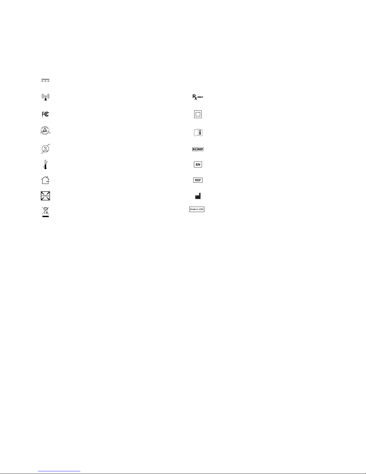
Symbols
e following symbols appear on the device, its labeling, or the device packaging. Each symbol carries a special
denition, as dened below:
Degrees of protection against the ingress of
Direct Current
Wireless Transmission For physician use only
Tested to comply with FCC Class B standards Protection against electrical shock - Class II
IPX0
water
Denotes compliance to CAN/CSA C22.2 No
601.1-M90 UL60601-1
Operating Humidity Ratings European Authorized Representative
Operating Temperature Ratings Serial Number
For indoor use only Reference Number
Fragile Manufacturer
is symbol indicates that the waste of
electrical and electronic equipment must not
be disposed as unsorted municipal waste and
must be collected separately. Please contact
the manufacturer or other authorized disposal
company to decommission your device.
Read Instructions for Use
Made in the USA
Product Description
e WiSe HDTV Receiver (Receiver) is an extension of the WiSe HDTV System and uses a radio frequency (RF)
link to receive high denition video and remote signals from the WiSe HDTV Transmitter (Transmitter). e
Receiver has one DVI and two remote outputs which allow it to be used with the Stryker Digital Capture (SDC)
device and Stryker surgical viewing displays with DVI input. It uses the same wireless technology as in the WiSe
HDTV System. e Receiver has a bi-color LED for device status, the same token and token slot as the current WiSe
HDTV system, compact wireless router style design with multiple placement options, and simple mode of operation.
e R1-R2 adapter (Optional Accessory) will be used on the Transmitter side to accept R1 and R2 cable connections.
Intended Use
e WISE HDTV Receiver, when connected with the compatible Stryker monitors/DVI devices, is intended for
wireless video display during surgical procedures including arthroscopy orthopedic surgery, laparoscopy (general
and gynecological surgery), thorascopy, endoscopy (general, gastroenterological and ENT surgery), and general
surgery.
e WISE HDTV Receiver, when connected with the SDC, is intended for wireless transfer of image data including
video and remote signal between medical devices (optional).
e WISE HDTV Receiver is a non-sterile reusable accessory not intended for use in the sterile eld. e WISE
HDTV Receiver is intended for use by qualied physicians having complete knowledge of these surgical procedures.
EN-3
Page 8
Indications and Contraindications
e WiSe HDTV Receiver, when connected with the Stryker display(s), as an accessory to the surgical camera, is
intended for visualization during surgical procedures including:
• General surgery
• General laparoscopy
• Nasopharyngoscopy
• Ear endoscopy
• Sinuscopy
• Plastic surgery wherever a laparoscope/endsocsope/arthroscope is indicated for use
• Other endoscopic surgeries including:
Laparoscopic cholecystectomy, laparoscopic hernia repair, laparoscopic appendectomy, laparoscopic pelvic
anterior spinal fusion, anterior cruciate ligament reconstruction, knee arthroscopy, shoulder arthroscopy,
small joint arthroscopy, decompression xation, wedge resection, exible endoscopy, urology, gynecology,
lung biopsy, pleural biopsy, dorsal sympathectomy, pleurodesis, internal mammary artery dissection for
coronary artery bypass, coronary artery bypass graing where endoscopic visualization is indicated and
examination of the evacuated cardiac chamber during performance of valve replacement.
ere are no known contraindications.
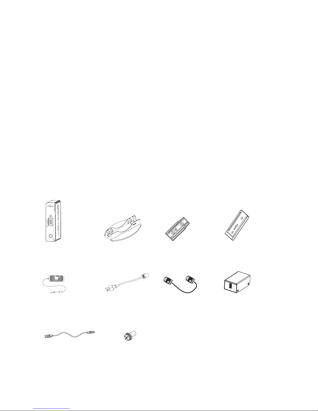
Package Content
REF# 0240030972 REF# P11883 REF# P11281 REF# P11139
(1) WiSe HDTV Receiver (1) Base Stand (1) Wall Mount Adapter (1) Wall Mount Plate
REF# P11142 REF# 0105033001 REF# 0105207131 REF# P12866
(1) AC Adapter (1) Hospital-grade
AC power cord
REF# P13014 REF# 0105207102
(1) USB A to B Cable
(Optional Accessory)
EN-4
(2) 6-32 x 5/16" Philips
Pan Split/Flat Washer
Sems
(1) DVI Cable, 3FT (1) R1-R2 Adapter
(Optional Accessory)
Page 9

Device Features
e Receiver can be used with the Transmitter (REF#0240030971), which allows it to receive a high-denition video
and remote signals over a radio-frequency link. is link is established by means of the token (REF#0240030974),
which is included with the Transmitter.
Front Panel Rear Panel
1
1
2
1. Token Status LED Provides feedback when
linking the Receiver and
the Transmitter
2. Token (Included with
the Transmitter)
3. Token Slot Site of insertion for
4. Power switch Powers the Receiver ON
Initializes the wireless
connection aer
insertion into the
Transmitter and the
Receiver and display
the token to establish a
wireless connection
and OFF
2
3
3
4
4
1. DC Power Inlet 5 VDC input; connects to
separable hospital-grade
AC power cord that can be
used for mains isolation
2. DVI Output Connects to SDC or any
other display
3. Remotes 1 and 2 Connects to SDC
4. RS232 Port Maintenance port
(not for customer use)
EN-5
Page 10

Setup
When the Receiver is used with other devices, leakage currents may be additive. Ensure that all
systems are installed according to the requirements of IEC 60601-1-1.
Warning
Connecting AC Power
Warning
Always set up the Receiver in a location that allows adequate ventilation. Insucient ventilation
may cause the Receiver to overheat and shut down.
Always use the hospital-grade AC power cord supplied with the Receiver.
1
2
1. Connect the AC adapter to the 5V input on the Receiver.
2. Connect the power cord to the power supply.
3. Connect to the AC mains using the supplied hospital-grade AC power cord.
3
Wall Mount Adapter Mounting Options
1. Line up dimple and thru holes.
Orient the Wall Mount Adapter in such a way that the dimple and thru holes line up with the blind hole and
threaded PEMS on the Receiver.
2. Secure the Wall Mount Adapter onto the Receiver console.
Use two 6-32 x 5/16" Phillips Pan Split/Flat Washer SEMS (REF#0105207102) using a Phillips screw driver.
EN-6
Page 11

Routing Video Conguration Setup #1
Please refer to diagram on the opposite page.
Notes:
• e devices listed in the diagram are examples only. e setup is applicable to compatible devices.
• Connect a video cable (DVI, VGA, S-Video) from the camera control device to a display to provide a wired backup
signal.
• Place the Receiver at least 4 feet (120 cm) away from the front panel of Transmitter #2.
• Ensure that the Receiver is not placed within Transmitter #2’s front eld of vision.
1. Connect a DVI cable from DVI Output 1 on the camera control device to the DVI Input on the Transmitter #1.
2. Connect the remote cables from the camera control device to the R1-R2 Adapter (Optional).
3. Connect a USB cable from the R1-R2 adapter to the Transmitter #1 (Optional).
4. Connect a DVI cable from the Receiver to the SDC DVI Input.
5. Connect the remote cables from the Receiver to the SDC.
6. Connect a DVI cable from the SDC Ouput to the DVI Input on the Transmitter #2.
7. Link the Transmitter #1 to the Receiver as shown.
8. Link the Transmitter #2 to up to 3 displays as shown (or up to 3 Receivers, or a combination of 3 Receivers and
displays).
EN-7
Page 12

HDTV TRANSMITTER
HDTV TRANSMITTER
Setup Example #1
Cart/Boom
Camera Control Device
Video Cable
WiSe HDTV Transmitter #1 (Back)
1 2
Hard Wired Connection
Wireless Connection
Wired Primary Display
(Front)
Doc Station
WiSe Receiver (Front)
(Back)
7
SDC Ultra
3
5
4
Operating Room
WiSe HDTV Surgical Display WiSe HDTV Surgical Display
WiSe HDTV Transmitter #2 (Back)
(Front)
6
8
WiSe HDTV Surgical Display
EN-8
Page 13

Routing Video Conguration Setup #2
HDTV TRANSMITTER
• Connect a DVI cable from the DVI Output on the:
1. Camera control device to the DVI Input on the SDC.
2. SDC to the DVI Input on the Transmitter.
3. Transmitter to the primary surgical display.
4. DVI Output on the Receiver to the auxiliary surgical display or DVI compatible device.
• Link the Transmitter to the Receiver as shown.
Setup Example #2
Camera Control Device
SDC Ultra
1
WiSe HDTV Transmitter (Front)
2 3
Hard Wired Connection
Wireless Connection
Wired Primary Display
Auxiliary Display
4
WiSe HDTV Receiver (Front)
(Back)
EN-9
Page 14

Instructions for Use
HDTV TRANSMITTER
Link the Transmitter to the Receiver
Cautions Devices that employ RF communications may aect the normal function of the Receiver. When
choosing a location for the Receiver, consult the “Electromagnetic Compatibility” section of this
manual to ensure proper function.
In accordance with patient privacy laws, do not transmit personal patient information, such as
EKG, EEG, patient name, or patient ID over the wireless signal.
Notes
• e following graphic will display for 5 minutes aer the
Receiver is turned on, or aer the connection is lost, or until
linking begins. is indicates that no connection has been
established between a Transmitter and the Receiver.
• e Receiver functions on a wireless 20 MHz channel in the 4.9 – 5.9 GHz spectrum. As necessary, remove other
wireless devices in the same frequency band from the environment to make channels available for the Transmitter
and the Receiver.
• To link the Receiver to the Transmitter, and thereby enable wireless communication, any blue Transmitter token will
suce.
• If multiple Transmitters are within 100 feet of each other, for example, in adjacent operating rooms, link each
Transmitter to its respective Receiver one set at a time. Wait 15 seconds before linking the next Transmitter/Receiver
set.
1
2
3
1. Power on the Transmitter and the Receiver. e token LED shines amber as the devices perform startup
functions and then turns o when there is no token inserted the token slot.
2. Insert the token into the Transmitter’s token slot. e token LED also shines amber as it writes the data.
3. When the token LED turns green, remove the token from the Transmitter.
4. Within 2 minutes, insert the token into the token slot on the Receiver. An audible tone will sound from the
Transmitter, and the token LED will change from amber to green when the Receiver and the Transmitter have
been linked.
5. Remove the token from the token slot on the Receiver.
5
4
EN-10
Page 15

Cleaning
Unplug the device from the electrical outlet before cleaning.
Warning
Cautions • Do not sterilize the device.
• Never submerge the Receiver or allow liquids to enter the Receiver. Wipe any cleaning agents
o the Receiver immediately using a water dampened cloth.
• e surface nish will be permanently damaged by strong chemicals and solvents such
as acetone and tricholoethylene. Damage caused by the use of unapproved substances or
processes will not be covered by warranty.
• It is recommend to test any cleaning solution on a small area of the Receiver that is not
visible to verify compatibility.
• Do not use steel wool or other abrasive material to clean the Receiver.
1. e Receiver may be cleaned with either Steris Coverage Spray HB Plus or ASP Enzol Enzymatic Detergent
Solution.
2. Spray the cleaning agent on a so cloth and wipe down the Receiver.
3. Using a dry, so cloth, dry the Receiver thoroughly.
EN-11
Page 16

Troubleshooting
Before returning the Receiver for service, consult the troubleshooting list below:
Problem Possible Cause Possible Solution
No picture No Power Ensure the power switch at the front and back of the display
are set to ON.
Check if the AC power cord is properly connected to the AC
adapter and outlet.
No Video Check if the video signal cable is properly connected at the
back of the Receiver.
Check if the power of the video signal source system is ON.
No picture and
LED stays amber
for longer than 10
seconds
LED stays amber
for longer than 10
seconds
Wireless link
not established
within 2 minutes
(with optional
Transmitter).
Wireless link
established with some
but not all Receivers
(with Transmitter).
Bad or
unprogrammed
token inserted
Bad or
unprogrammed
token inserted
System is busy Wait for 10 seconds.
System error has
occurred
“Digital RGB No
Signal” on screen
image
“No Link” on
screen image
“Digital RGB No
Signal” on screen
image
Re-insert the token into the Transmitter. Repeat steps 2
through 4 of the “Linking the Transmitter to Receiver”
instructions section on the aected Receiver only.
Re-insert the token into the Transmitter. Repeat steps 2
through 4 of the “Linking the Transmitter to Receiver”
instructions section on the aected Receiver only.
Restart the Receiver. Repeat steps steps 2 through 4 of the
“Linking the Transmitter to Receiver” instructions section on
the aected Receiver only.
Cycle the power by cycling the hard power switch at the front
of the Transmitter. Repeat steps 2 through 4 of the “Linking
the Transmitter to Receiver” instructions section on the
aected Receiver only.
Cycle the power on the aected Receiver. Repeat steps 2
through 4 of the “Linking the Transmitter to Receiver”
instructions section on the aected Receiver only.
Poor video quality or
trouble establishing/
maintaining a
wireless link
EN-12
Interference Reorient or relocate the Receiver.
Connect the device to an outlet on a circuit dierent from that
to which the other device(s) are connected.
Consult the manufacturer or sales representative for help.
Page 17

Technical Specifications
Video Output
Digital Connector: One Digital Video Interface (DVI),
29-pin DVI-I
Remote Output Connector: 2.5mm phone jack
Video Formats
1920 × 1080 @ 60 Hz/50Hz
1280 × 1024 @ 60Hz/50 Hz
1280 × 720 @ 60 Hz/50Hz
1024 x 768 @ 60 Hz
Operating Conditions
Temperature: 41 – 104°F (5 – 40°C)
Relative Humidity: 30 - 95%
Transport and Storage Conditions
Temperature: -0.4 – 140°F (-18 – 60°C)
Relative Humidity: 15 - 90%
Electrical
AC Adapter Model: MW172KB0503F01
Input: 100-240 VAC, 50-60 Hz, 0.5 A
Output: +5VDC, 3.0 A
Compliance
Medical Safety Standards
IEC 60601-1:1988 + A1:1991 + A2:1995
CAN/CSA C22.2 NO.601.1-M90:2003
UL 60601-1:2003
AS/NZS 3200.1.0:1998
CSA 22.2.601.1.1:2002
Medical EMC Standard
IEC 60601-1-2:2007
ETSI EN 301 489 V1.8.1
IC Regulations
IC:7680A-AMN11100 (WiSe HDTV Transmitter)
IC:7680A-AMN12100 (WiSe HDTV Display,
WiSe HDTV Receiver)
FCC Regulations
FCC 15B 2008 (Class B)
FCC Identier: VQSAMN12100R44
Please contact your local Stryker Endoscopy sales
representative for information on changes and new
products.
Total Shipping Weight
6.8 lb
Dimensions
Receiver Console: 1.750" W x 9.388" L x 7.000" H
(4.4 cm w x 23.8 cm l x 17.7 cm h)
Wireless
Frequency: 4.9 – 5.9 GHz
Channel Bandwidth: 20 MHz
Channel Allocation: Automatic frequency selection
with prescan
Protocol: Orthogonal Frequency Division
Multiplexing (OFDM) with Multiple Input Multiple
Output (MIMO)
Classication
Class II Equipment
Water Ingress Protection, IPX0 — Ordinary
Equipment
Continuous Operation
EN-13
Page 18

Electromagnetic Compatibility
When this device is connected with other electrical equipment, leakage currents may be additive. To minimize total leakage current per patient, ensure that all systems are
Warning
Caution Portable and mobile RF communications equipment may aect the normal function of the Receiver.
Like other electrical medical equipment, the Receiver requires special precautions to ensure electromagnetic compatibility with other electrical medical devices. To ensure electromagnetic
compatibility (EMC), the Receiver must be installed and operated according to the EMC information provided in this manual. e Receiver has been designed and tested to comply with IEC
60601-1-2:2001 requirements for EMC with other devices. e WiSe HDTV Receiver is intended for use inthe electromagnetic environment specied below. e customer or the user of the WiSe
HDTV Receiver should ensure it is used in such an environment.
Guidance and Manufacturer’s Declaration: Electromagnetic Emissions
Emissions Test Compliance Electromagnetic Environment - guidance
RF emissions CISPR 11 Group 1 e WiSe HDTV Receiver uses RF energy only for its internal function; therefore, its RF emissions are very low and are not
RF emissions CISPR 11 Class B e WiSe HDTV Receiver is suitable for use in all establishments other than domestic establishments and those directly
Harmonic emissions IEC61000-3-2 Class A
Voltage Fluctuations/ icker emissions
IEC61000-3-3
Guidance and Manufacturer’s Declaration: Electromagnetic Immunity
Immunity Test IEC 60601 Test Level Compliance Level Electromagnetic Environment Guidance
Electrostatic Discharge (ESD)
IEC61000-4-2
Electrical fast transient/burst
IEC61000-4-4
Surge
IEC61000-4-5
Voltage dips, short
interruptions and voltage
variations on power supply
input lines
IEC61000-4-11
Power frequency (50/60Hz)
magnetic eld
IEC 61000-4-8
Note: Ut is the AC mains voltage prior to application of the test level.
installed according to the requirements of IEC 60601-1-1.
Do not use cables or accessories other than those provided with the Receiver, as this may result in increased electromagnetic emissions or decreased immdevicey to such
emissions.
If the display is used adjacent to or stacked with other devices, observe and verify normal operation of the display and transmitter in the conguration in which it will be
used prior to using it in a surgical procedure. Consult the tables below for guidance in placing the Receiver and Transmitter.
likely to cause any interference in nearby electronic equipment.
connected to the public low-voltage power supply network that supplies buildings used for domestic purposes, provided the
following warning is heeded:
Warning: is system is intended for use by health care professionals only. is system may cause radio interference or may
Complies
6kV contact
8kV air
2kV for power supply lines
1kV for input/output lines
1kV dierential mode
2kV common mode
<5% Ut (>95% dip in Ut) for 0.5 cycle
40% Ut (60% dip in Ut) for 5 cycles
70% Ut (30% dip in Ut) for 25 cycles
<5% Ut (>95% dip in Ut) for 5 sec.
3.0 A/m 3.0 A/m Power-frequency magnetic elds should be at levels characteristic of a
disrupt the operation of nearby equipment. It may be necessary to take mitigation measures, such as reorienting or relocating
the system or shielding the location.
6kV contact
8kV air
2kV line to ground
1kV line to line
1kV dierential mode
2kV common mode
<5% Ut (>95% dip in Ut) for 0.5 cycle
40% Ut (60% dip in Ut) for 5 cycles
70% Ut (30% dip in Ut) for 25 cycles
<5% Ut (>95% dip in Ut) for 5 sec
Floors should be wood, concrete, or ceramic tile. If oors are covered
with synthetic material, the relative humidity should be at least 30%.
Mains power quality should be that of a typical commercial or hospital
environment.
Mains power quality should be that of a typical commercial or hospital
environment
Mains power quality should be that of a typical commercial or hospital
environment. If the user of the transmitter requires continued operation
during power mains interruptions, it is recommended that the WiSe
HDTV Receiver be powered from an uninterruptible power supply or
a battery.
typical location in a typical commercial or hospital environment.
EN-14
Page 19

Guidance and Manufacturer’s Declaration: Electromagnetic Immdevicey
Portable and mobile RF communications equipment should be used no closer to any part of the WiSe HDTV Receiver, including its cables, than the recommended separation distance calculated
from the equation applicable to the frequency of the transmitter.
Immunity Test IEC 60601 Test level Compliance Level Electromagnetic Environment Guidance
Recommended Separation Distance
Conducted RF
IEC 61000-4-6
Radiated RF
IEC 61000-4-3
Notes:
• At 80 MHz and 800 MHz, the higher frequency range applies.
• ese guidelines may not apply in all situations. Electromagnetic propagation is aected by absorption and reection from structures, objects, and people.
(a) Field strengths from xed transmitters, such as base stations for radio (cellular/cordless) telephones and land mobile radios, amateur radio, AM and FM radio broadcast, and TV broadcast,
cannot be predicted theoretically with accuracy. To assess the electromagnetic environment due to xed RF transmitters, an electromagnetic site survey should be considered. If the measured eld
strength in the location in which the WiSe HDTV Receiver is used exceeds the applicable RF compliance level above, the display and transmitter should be observed to verify normal operation. If
abnormal performance is observed, additional measures may be necessary, such as reorienting or relocating the WiSe HDTV Receiver.
(b) Over the frequency range 150 kHz to 80 MHz, eld strengths should be less than 3 V/m.
0.15 - 80 MHz
3 Vrms 1 kHz
80 MHz - 2.5 GHz
3 V/m 80% @ 1 kHz
0.15 - 80 MHz
3 Vrms 1 kHz
80 MHz - 2.5 GHz
3 V/m 80% @ 1 kHz
d = 1.17√P
d = 1.17√P 80 MHz to 800 MHz
d = 2.33√P 800 MHz to 2.5 GHz
where P is the maximum output power rating of the transmitter in watts (W) according to the
transmitter manufacturer and d is the recommended separation distance in meters (m).
Field strengths from xed RF transmitters, as determined by an electromagnetic site survey (a),
should be less than the compliance level in each frequency range (b).
Interference may occur in the vicinity of
equipment marked with the following symbol
Recommended Separation Distances Between Portable and Mobile RF Communications Equipment and the WiSe 26” HDTV Receiver
e WiSe HDTV Receiver is intended for use in an electromagnetic environment in which radiated RF disturbances are controlled. e user of the WiSe HDTV Receiver can help prevent
electromagnetic interference by maintaining a minimum distance between portable and mobile RF communications equipment (transmitters) and the WiSe HDTV Receiver as recommended
below, according to the maximum output power of the communications equipment.
Rated maximum output power
(W) of transmitter
0.01 0.12 0.12 0.23
0.1 0.37 0.37 0.74
1 1.17 1.17 2.33
10 3.70 3.70 7.37
100 11.70 11.70 23.30
For transmitters rated at a maximum output power not listed above, the recommended separation distance (d) in meters (m) can be estimated using the equation applicable to the frequency of
the transmitter, where P is the maximum output power rating of the transmitter in watts (W) according to the transmitter manufacturer.
Notes:
• At 80 MHz and 800 MHz, the separation distance for the higher frequency range applies.
• ese guidelines may not apply in all situations. Electromagnetic propagation is aected by absorption and reection from structures, objects, and people.
Separation distance (m) according to frequency of transmitter
150 kHz to 80 MHz
d = 1.17√P
80 kHz to 800 MHz
d = 1.17√P
800 kHz to 2.5 GHz
d = 1.17√P
EN-15
Page 20

Page 21

Page 22

Page 23

Page 24

Stryker Endoscopy
5900 Optical Court
San Jose, CA 95138 USA
1-800-624-4422
U.S. Patents: www.stryker.com/patents
WiSe™ is a trademark of Stryker Corporation.
Products referenced with ™ designation are trademarks of Stryker.
Products referenced with ® designation are registered trademarks of Stryker.
Produced for Stryker Endoscopy.
2016/02
 Loading...