

Page 1
Stryker Visum 300® Ceiling-Mounted Exam Light
Assembly, Operations, and Maintenance Manual
Page 2

Page 3

S
Contents
1. Indications for Use .............................................................................................................................................4
1.1 Item Installation Package List .......................................................................................................................... 4
2. Warnings and Cautions .....................................................................................................................................5
2.1 Warnings .................................................................................................................................................................5
2.2 Cautions ................................................................................................................................................................... 5
3. Product Symbol Denition ...............................................................................................................................6
4. VISUM® 300 Components .................................................................................................................................7
5. Installation ........................................................................................................................................................... 8
5.1 Installing the Down Tube Assembly .............................................................................................................. 8
5.2 Installing the Extension Arm with the Spring Arm ................................................................................12
5.3 Attaching the Light Head ................................................................................................................................12
6. Operations .........................................................................................................................................................14
6.1 Turning the Light On and O .........................................................................................................................14
6.2 Positioning the Light Head/Suspension ....................................................................................................14
6.3 Removing and Reattaching the Sterilizable Light Handle Cover......................................................14
6.4 Cleaning and Disinfecting the Sterilizable Light Handle Cover ........................................................16
6.4.1 Cleaning .................................................................................................................................................16
6.4.2 Sterilization ........................................................................................................................................... 16
6.5 Replacing the Halogen Bulb ..........................................................................................................................17
6.6 Replacing Fuses ..................................................................................................................................................19
6.7 Replacing the Transformer ..............................................................................................................................20
6.8 Replacing the Aesthetic Covers ....................................................................................................................22
6.9 Removing the Light Head ...............................................................................................................................24
6.10 Removing the Extension Arm with the Spring Arm ..............................................................................24
6.11 Removing the Down Tube Assembly ..........................................................................................................25
6.12 Lubricating the Keeper Clip ............................................................................................................................25
6.13 Adjusting the Spring Force .............................................................................................................................25
7. Troubleshooting ...............................................................................................................................................27
7.1 Light Does Not Function .................................................................................................................................27
8. Technical Specications ..................................................................................................................................28
8.1 Environmental Specications ........................................................................................................................28
8.2 Electrical Specications ...................................................................................................................................28
8.3 Lighting Data .......................................................................................................................................................28
8.4 Physical Data ........................................................................................................................................................28
9. Maintenance......................................................................................................................................................29
10. Product Disposal ............................................................................................................................................30
11. Damage Claims ...............................................................................................................................................30
12. Stryker Limited Warranty .............................................................................................................................30
13. Contact Information ......................................................................................................................................31
3
Page 4

S
1. Indications for Use
The intended use of the Stryker VISUM® Lighting system is to illuminate the patient’s surroundings, as well
as the body of the patient to support diagnosis and treatment. It has not been designed as a surgical light,
or for use by the patient.
The VISUM® is considered a Class I medical device. It is a luminaire for diagnosis meant to illuminate the
body of the patient locally in order to support diagnosis or treatment which could be interrupted without
any hazard for the patient in case of failure of the light. It is not intended for use in operating rooms.
1.1 Item Installation Package List
1. Down Tube Assembly (see Figure 5)
• Down Tube
• Ceiling Cover
• Protective Cover
2. Extension Arm and Spring Arm Assembly (see Figures 1, 8, 9):
• Plug
• C-Clip / Retaining Ring
• C-Clip / Retaining Ring Installation Pliers
• Light Head Keeper Clip
• Brake Screw
• Brake Cover
• Protective Cap
• Keyed Washer
• Flat Washer
3. Light Head Assembly:
• Light Head (see Figure 2)
• Sterilizable Handle (see Figure 3)
4. Installation, Operations, and Maintenance Manual
5. Installation Hardware Kit:
3/8” UNC Threaded Rods, 12”
Long
4
Flat Washers Lock/Spring Washers 3/8” Nuts
Page 5
S
2. Warnings and Cautions
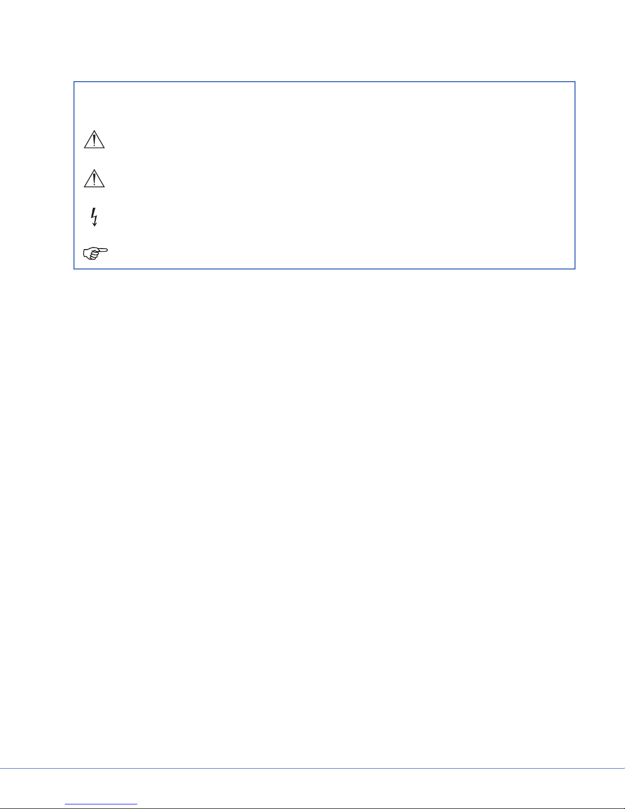
Please read this manual and follow its instructions carefully. The words WARNING, CAUTION, and Note
carry special meanings and should be carefully reviewed:
Warning: The personal safety of the patient or user may be involved. Disregarding this
information could result in injury to the patient or user.
Caution: Special service procedures or precautions must be followed to avoid damaging the
instrument.
Warning: A lightening bolt is intended to warn of the presence of hazardous voltages. Refer
all service to authorized personnel.
Note: Special information to make maintenance easier or important information more clear.
To avoid potential serious injury to the user and the patient and/or damage to this device, the user must
adhere to the following warnings and cautions.
2.1 Warnings
1. Read this manual thoroughly, and be familiar with its contents prior to using this equipment.
2. This equipment can only be used by (or on the order of) a physician.
3. Test this equipment prior to any procedures. This product was fully tested at the factory before
shipment.
4. Do not remove or disable components. It may cause electric shock.
5. Attempt no repairs or adjustments, unless specically instructed to do so in this operating manual.
6. Disconnect the unit from the electric outlet before inspecting or servicing system components.
7. Do not look directly into the exam light while powered on.
8. Do not operate the exam light if any component of the light (such as the glass) is damaged.
2.2 Cautions
1. Do not add additional weight to the exam lights.
2. Do not place anything over the exam lights.
3. Follow the care and cleaning instructions in this manual.
4. Adjustments, modications, and/or repairs not described in this manual should be performed only by
Stryker personnel.
5. The electrical installation of the operating room must comply with any applicable IEC, CEC, NEC
requirements as well as the local codes and pre-installation manual.
5
Page 6
S
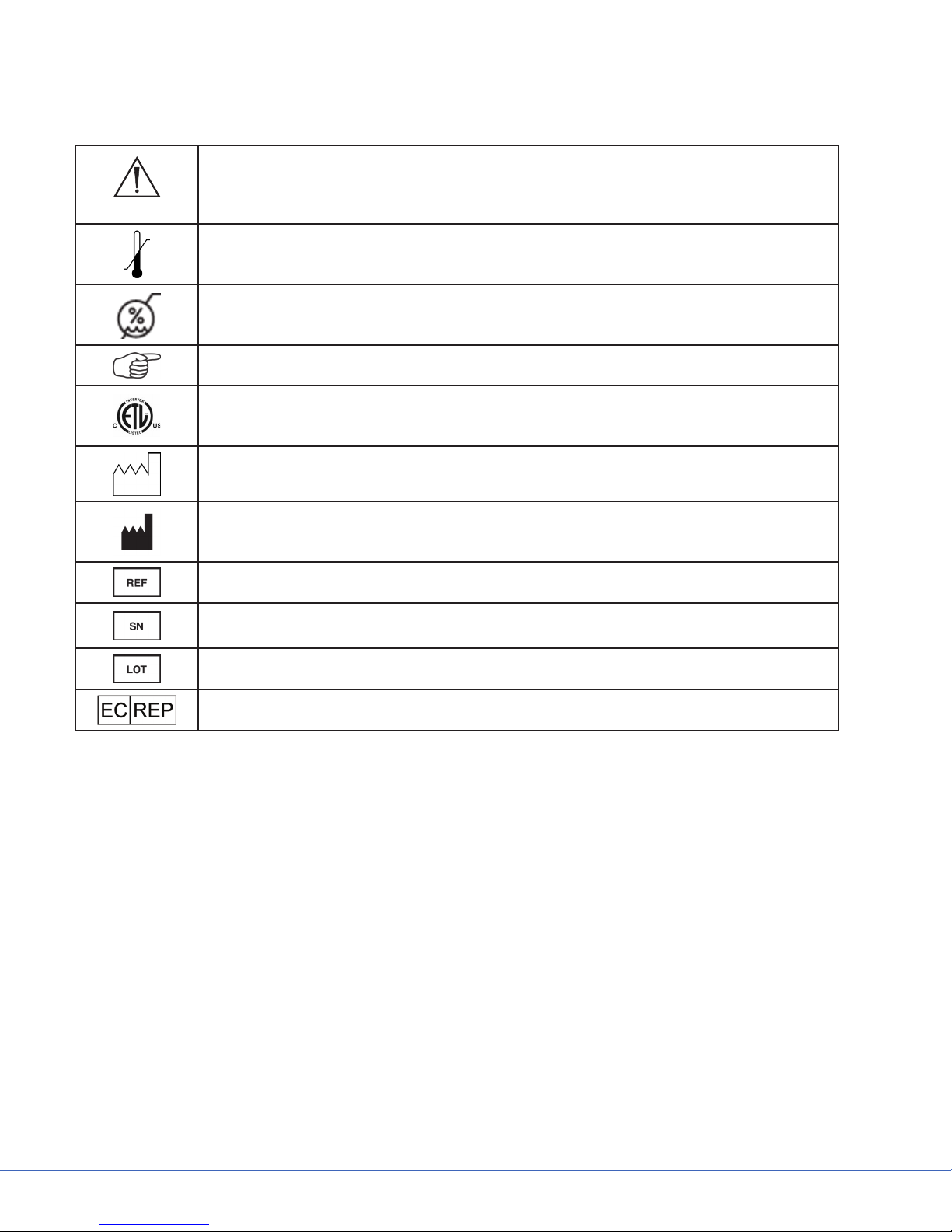
3. Product Symbol Denition
The following symbols may be found on the Stryker VISUM® 300 Ceiling-Mounted Exam Light:
An exclamation mark within a triangle is intended to alert the user to the presence
of important operating and maintenance (service) instructions in the literature
accompanying the product.
Denotes temperature limits.
Denotes humidity limits.
Denotes usage tips and useful information.
Denotes compliance to CSA Standard C22.2, 60601.1 - M90, AS 3200, IEC 60601, IEC
60601-2-41, UL 60601, EN 60601
Denotes the date the equipment was manufactured.
Denotes the manufacturer of the device.
Denotes product/part number.
Denotes product/serial number.
Denotes lot or batch number.
Denotes European Representative.
6
Page 7
4. VISUM® 300 Components
REVISIONS
REV. DESCRIPTION ECO DATE CHECK APPROVED
1
2
3
4
5
6
S
8
9
7
11
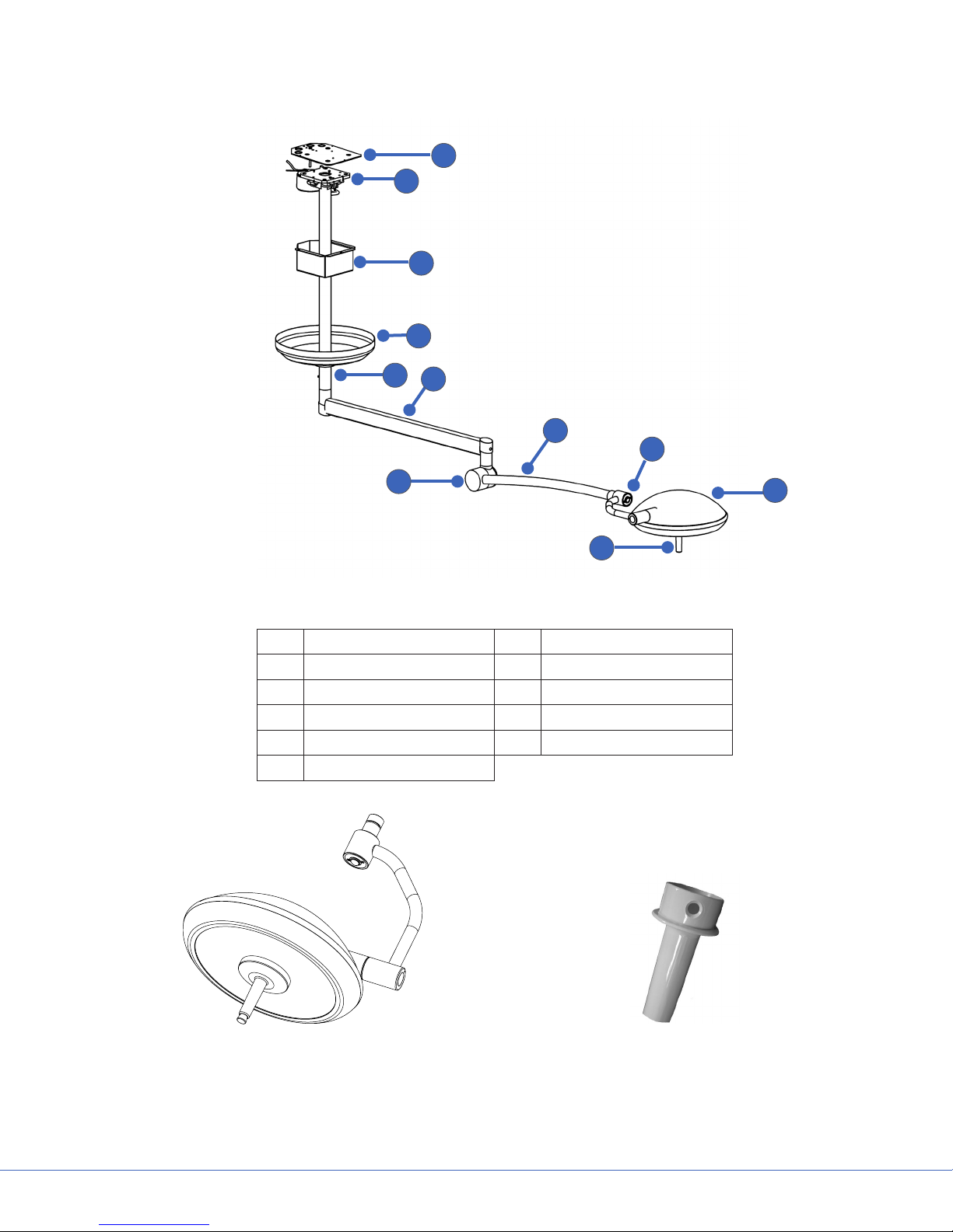
Figure 1 - VISUM® 300 Components
1. Sheet Metal Guard 7. Elbow
2. Down Tube Flange 8. Spring Arm
3. Sheet Metal Enclosure 9. Power Switch
4. Ceiling Cover 10. Light Head
5. Down Tube 11. Light Handle Assembly
6. Extension Arm
10
7
Figure 2 - VISUM® 300 Light Head Figure 3 - Sterilizable Handle
Page 8

S
5. Installation
Warning
• The light should be installed down circuit from a circuit breaker, or should be installed with a switch
to turn the main power o.
• Make sure that the power to the installation site is o during all installation procedures.
Refer to the VISUM® 300 Ceiling-Mounted Exam Light Pre-Installation Manual for load data on the VISUM®
300 CM. (Installation hardware is provided with all products and should be in the nal package.)
5.1 Installing the Down Tube Assembly
The following steps assume a ceiling structure with the hole pattern specied in the VISUM® 300 CeilingMounted Exam Light Pre-Installation Manual. Refer to Figures 4-7 as needed.
1. Loosen the three set screws and remove the retaining ring and ceiling cover.
2. Inspect the ceiling structure.
Warning
Make sure that the super structure is at least 3-8” above the false ceiling, as shown in Figure 4.
3. Attach the down tube assembly to the ceiling super structure as follows:
• Insert and fasten the threaded rods into the ceiling super structure as shown in Figure 5.
• Install the upper 3/8” nuts and at washers onto the threaded rods as shown in Figure 5. Depending
on down tube length, ensure that the bottom of the washer is the correct height above the bottom
of the false ceiling.
• Raise the down tube assembly into the ceiling while guiding the threaded rods into the holes in the
down tube ange shown in Figure 6.
• Install the lower at washers, spring washers, and 3/8” nuts onto the threaded rods as shown in Figure
7.
4. Make sure the ceiling plate is level in two directions.
5. Have an electrician:
• Run conduit with ¾” tting into the sheet metal guard.
• Run 6’ power cable through the conduit and connect the lines at the junction box.
6. Raise the sheet metal enclosure and hand tighten the three screws to the sheet metal guard. Use a
Phillips screw driver to tighten the remainder.
7. Raise the ceiling cover and retaining ring to the ceiling and fasten the three set screws. Make sure the
ceiling cover is ush with the bottom of the false ceiling.
8
Page 9
Access
Panel
S
Super Structure
Customer Provided
3-8”
FALSE CEILING
Down Tube Flange with Ceiling
Ceiling Cover
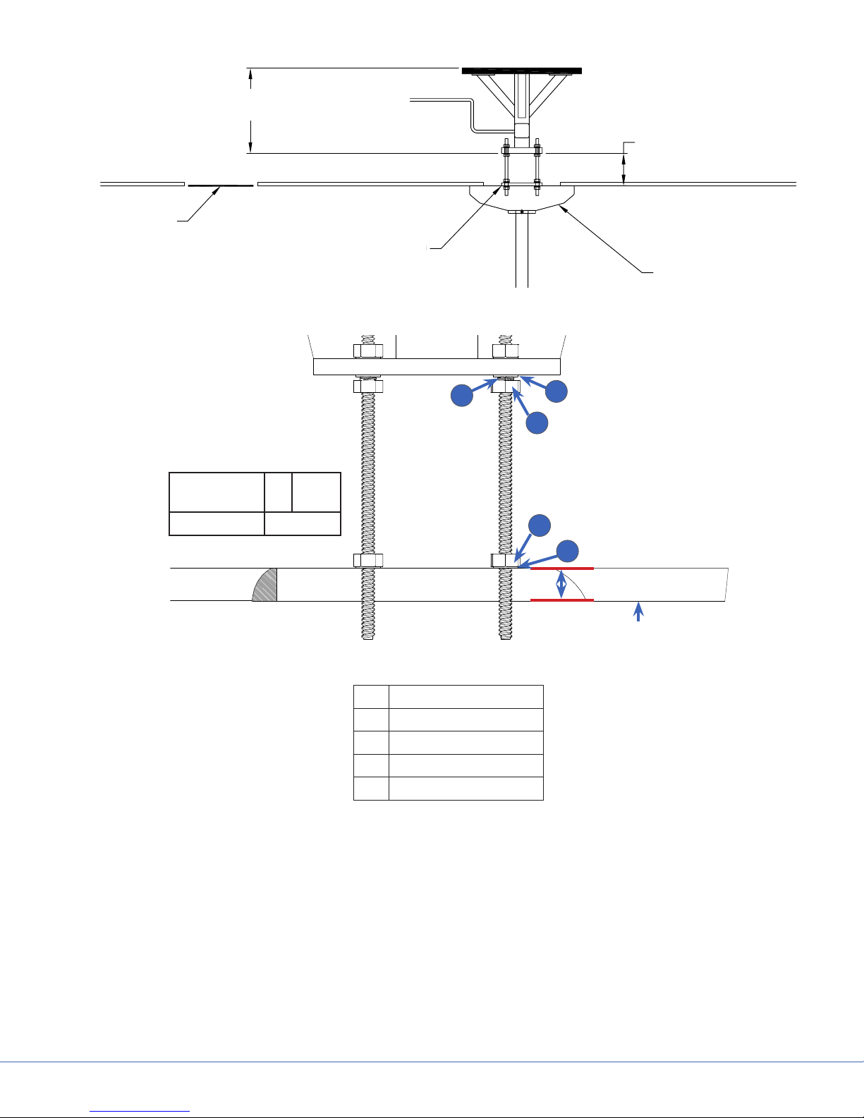
Figure 4 - Down Tube, Super Structure, and False Ceiling
Down Tube
Height H
110mm 1”
220-800mm 1”-2”
1
+ .25”
- 0
Figure 5 - Down Tube Assembly Preparation
1. Spring Washer
2. Flat Washer
3. Nut
4. Upper Nut
5. Upper Flat Washer
2
3
4
5
H
Bottom of False Ceiling
9
Page 10
S
1
2
3
4
5
6
7
8
9
10
11
12
13
14
15
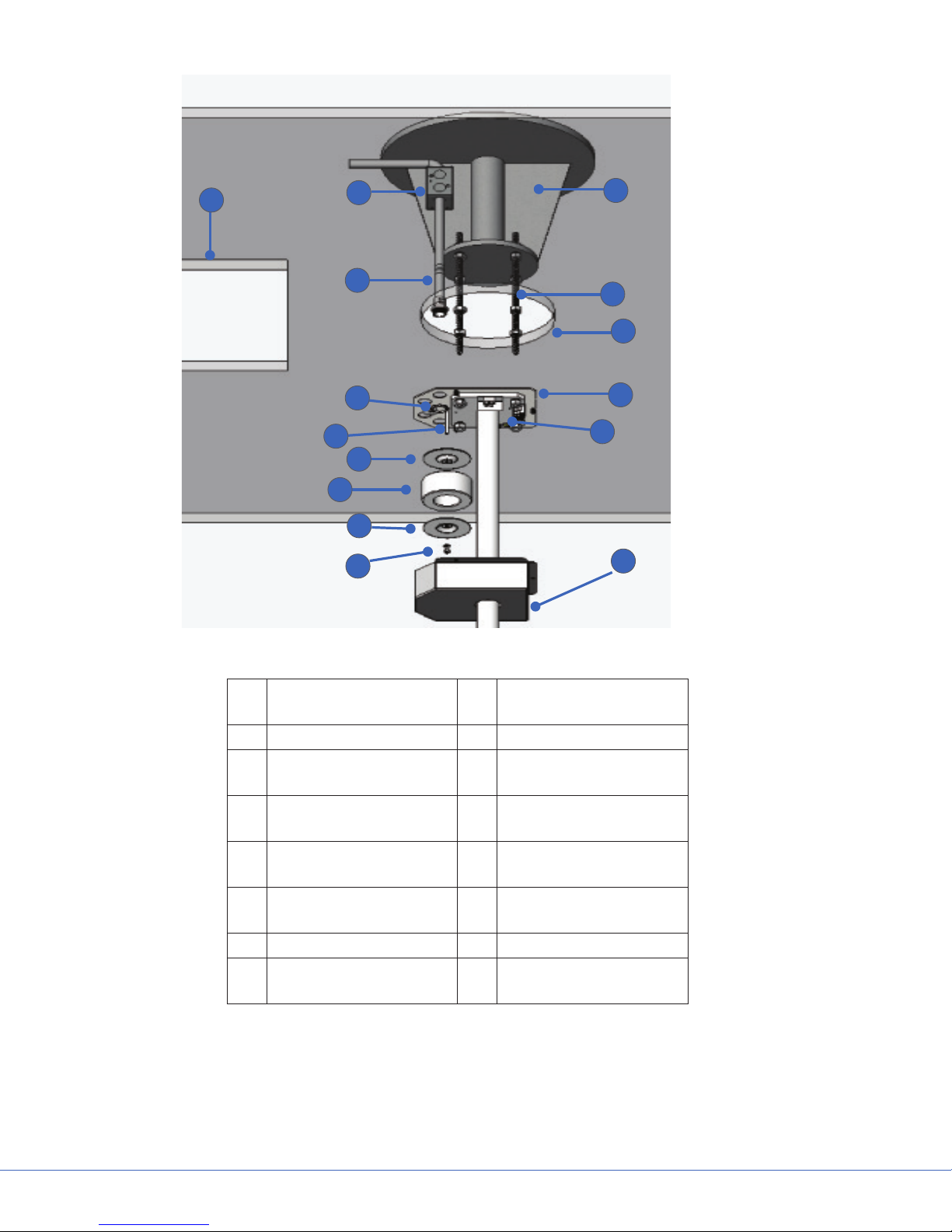
Figure 6 - Detail of Installation Without Ceiling Cover
1. Access Panel 9. Transformer Clamping
Nut and Washer
2. Junction Box 10. Ceiling Structure
3. Conduit and Fitting
(Customer Supplied)
4. Conduit Fitting Nut
(Customer Supplied
5. Transformer Mounting
Screw
6. Transformer Insulating
Ring
7. Transformer 15. Sheet Metal Enclosure
8. Transformer Clamping
Ring
11. Threaded Rod
12. False Ceiling
13. Sheet Metal Guard
14. Down Tube Flange
10
Page 11

S
3
2
1
4
6
5
11
9
8
10
Figure 7 - Bolt, Nut, and Washer Installation
1. Conduit Fitting
(Customer Supplied)
2. Down Tube Flange 7. Lower Flat Washer
3. Sheet Metal Guard 8. Lower Nut
4. Upper Nut 9. Spring Washer
5. Upper Flat Washer 10. Sheet Metal Enclosure (Customer
6. False Ceiling
Supplied)
11. Conduit Fitting Nut (Customer
Supplied)
7
11
Page 12

S
5.2 Installing the Extension Arm with the Spring Arm
Perform the following steps to install the extension arm with the spring arm. Refer to Figure 8 as needed.
1. Unscrew the Phillips-head screw.
2. Remove and discard the protective cover
installed on the down tube axle (not shown in
Figure 8).
3. Push the extension arm with the spring arm
onto the down tube assembly.
4. Insert the keyed washer into the hole, and install
the C-clip/retaining ring.
1
Warning
• Make sure the retaining ring is seated
correctly in the down tube C-clip slot. Do
not overextend the C-clip when installing.
Overextending the C-clip will prevent the
C-clip from locking into the down tube
axle, which could result in the extension
arm falling and causing serious injuries.
• If the keyed washer is not installed, the
retaining ring can become loose. If this
occurs, equipment can fall from xtures,
causing serious injuries.
8
2
3
4
5
6
7
Figure 8 - Installing the Extension Arm
5. Make sure the suspension is seated rmly.
6. Insert the plug into the bottom of the down
tube.
7. Tighten the Phillips-head screw to secure the
plug.
Down Tube Axle
1.
Hole for Keyed Washer
2.
Suspension
3.
Phillips-Head Screw
4.
5.
6.
7.
8.
Keyed Washer
C-Clip/Retaining Ring
Plug
Suspension
5.3 Attaching the Light Head
Perform the following steps to attach the light head to the spring arm. Refer to Figure 9 as needed.
1. Make sure the power to the suspension is disconnected.
2. Pull the spring arm down until it reaches the stop.
Warning
The spring arm is under high spring tension. Since the arm is not in its highest position when this
procedure is performed, the arm may jump suddenly, causing injury.
12
Page 13

S
Caution
Do not attempt to push the spring arm beyond its stop(s). Doing so will cause damage to the spring
arm.
3. Remove and discard the protective cap on the spring arm.
4. Install the brake cover over the spring arm so that the keeper clip slots in the spring arm and brake cover
are aligned.
5. Push the end of the light head into the spring arm, and install the keeper clip.
6. Rotate the brake cover 180° until it is lined up with the hole, and install the brake screw.
2
1
4
5
3
Figure 9 - Attaching the Light Head
1. Keeper Clip
2. Brake Screw
3. End of Light Head
4. Brake Cover
5. Slot
13
Page 14

S
6. Operations
6.1 Turning the Light On and O
The switch for turning the light on and o is located at the end of the light head, as shown in Figure 10. The
“On” setting is indicated on the switch by a “1”; the “O” setting is indicated by a “0”.
Figure 10 - Light On/O Switch
6.2 Positioning the Light Head/Suspension
Warning
The light head should be positioned at least 24 inches from the patient, in order to prevent burns and
wound drying. Positioning the light head at this distance also ensures optimal performance.
The light can be positioned in various ways using the light head handle. The light can be used with or
without a sterilizable handle.
The head itself may be rotated 360° and tilted 180°. The spring arm and horizontal arm can be moved
separately. The spring arm has 90° of vertical movement and 360° of horizontal movement. The extension
arm also has 360° of horizontal movement. You can adjust the positioning of the light as shown in Figure 11.
6.3 Removing and Reattaching the Sterilizable Light Handle Cover
Perform the following steps to remove and reattach the sterilizable light handle cover. Refer to Figure 12 as
needed.
1. To remove the optional sterilizable handle cover, press the round metal button at the base of the handle,
and pull the cover o of the handle.
2. To reattach the cover, align the hole on the cover and the button on the handle, then slide the cover into
place.
3. Twist the handle cover, until you hear a click, indicating that the handle cover is locked in place.
14
Page 15

S
D
8
7 65
4
3
2
1
E
F
D
C
B
7 65
4
3
2
1
E
F
D
C
B
2
1
E
F
D
4
3
2
1
E
F
Side View
90°
360°
360°
360°
Bottom View
180°
Figure 11 - Positioning the Light Head/Suspension
1. Button
2. Handle
1
2
Figure 12 - Sterilizable Light Handle Cover
15
Page 16

S
6.4 Cleaning and Disinfecting the Sterilizable Light Handle Cover
Cautions
• The button is not sterilizable.
• Power o system before cleaning. Make sure that no cleaning uid enters the system.
• To avoid damage to plastic parts, do not use any scouring, alkaline, acidic, or alcohol-based cleaning
agents.
• Allow the light to cool before disinfecting.
• Handles are shipped non-sterile. Clean and sterilize handles prior to use.
Note: Cleaning and disinfecting must be carried out by trained personnel.
Wipe the surfaces with a cloth and, if required, a mild cleaning solution.
6.4.1 Cleaning
1. Rinse the handle under running lukewarm water, ushing water through all passages.
2. Submerge the entire handle in an enzyme-action detergent prepared according to the manufacturer’s
recommendations. Remove debris and bioburden from all surfaces using a soft brush.
3. Rinse the handle thoroughly under running lukewarm water, ushing water through all passages.
4. Dry the handle with a lint-free cloth and inspect the handle to make sure it is free of debris.
6.4.2 Sterilization
The sterilization methods in the following table have been validated:
Sterilization Method Temperature Exposure Time
Gravity-displacement steam sterilization (single-wrapped) 132 °C (270 °F) 10 minutes
Gravity-displacement steam sterilization (double-wrapped) 121 °C (250 °F) 25 minutes
Pre-vacuum cycle (double-wrapped) 134 °C (273 °F) 2 minutes
Note: These cleaning and sterilization instructions are only recommended instructions and
may vary among hospitals depending upon the type of cleaning/sterilization equipment and
possible pathogens in the particular area. These instructions represent exposure time and not
total cycle time. The recommended cleaning/sterilization parameters may be modied based
on standard hospital cleaning/sterilization protocol.
16
Page 17

6.5 Replacing the Halogen Bulb
Perform the following steps to replace the halogen bulb.
Warning
Allow the light to cool before attempting maintenance.
Caution
Do not touch the halogen bulb directly; instead, grasp the reector.
1. After the light has been turned o and allowed to cool, remove
the optional sterile handle if necessary.
2. Unscrew the two thumbscrews at the base of the handle
assembly, and the pull the handle assembly straight out of the
light head.
S
3. Firmly grasp the bulb and pull straight out from the handle
assembly to remove it.
4. Using the screwdriver provided, remove the porcelain bulb
holder by removing the two screws.
5. Remove bulb and porcelain from packaging.
17
Page 18

S
6. Remove the bulb from porcelain bulb holder.
7. Insert the new bulb holder and tighten the two screws
8. Insert the replacement bulb into the socket of the porcelain bulb
holder.
9. Replace the handle assembly. Guide the banana clips into the
power receptacles, ensuring that the handle assembly is seated
against the face glass.
10. Secure with the two thumbscrews at the base of the handle
assembly.
Light Handle Light Head
Side Side
18
Page 19

6.6 Replacing Fuses
Warning
Turn o the light and disconnect power from the unit before changing the fuses.
Perform the following steps to replace fuses.
1. Remove the ceiling cover by unscrewing the three set screws
and then sliding the cover down the down tube, as shown in the
picture to the right.
2. Remove the sheet metal enclosure by unscrewing the three
captive screws and then sliding it down the tube.
Note: For short down tubes, the removal of the
extension arm may be necessary in order to obtain
access to the ange.
3. Grasp the black plastic fuse holders (indicated in the picture to
the right) with two ngers and pull rmly to remove.
4. Check the fuses and replace them if necessary.
• For 115V models, use a 1 amp fuse
S
5. Slide the fuse holders (see the sample to the right) back into
place.
Note: The fuse holders can only be inserted in one direction. If you are having diculty
inserting the fuse holders back into place, make sure that they are facing the correct direction.
19
Page 20

S
6.7 Replacing the Transformer
Warning
Turn o the light and disconnect power from the unit before changing the transformer.
Perform the following steps to replace the transformer.
1. Remove the light head and spring arm assembly according to the “Removing the Light Head” and
“Removing the Extension Arm with the Spring Arm” procedures in the Stryker VISUM® 300 CeilingMounted Exam Light Installation, Operations, and Maintenance Manual.
2. Remove the ceiling cover and the sheet metal enclosure
from the ceiling.
3. Have an electrician power down the room and disconnect
the power cord at the ange.
4. Tape up the end of the black cable (shown) so that the
loose wires are not spread out, and attach a string to the
end of the black cable (for pulling the cable back through
the down tube later in this procedure).
Warning
An electrician must power down the room and unterminate the power cord at the ange.
5. Remove the three “hex” screws holding the commutator
assembly in the down tube.
6. Make sure all wiring has been disconnected from the
transformer.
20
Page 21

7. Gently pull the commutator assembly out of the down tube
while also feeding cable through hole at the top of the down
tube. Attach a pull-string to the cable to help pull the cable
back after installing the new transformer.)
8. Unthread the clamping nut and clamping components to
remove the transformer from the assembly.
9. Install the new transformer along with the clamping
components, rethreading the clamping nut to hold it in place.
Note: If the part is still hanging from the ceiling,
watch out that transformer does not fall when
all wiring is disconnected and cable is pulled
into the down tube.
S
10. Reinstall the three hex screws that hold the commutator
assembly. Take special note of the visible hole and screw
distance shown to the right, so as to avoid inserting the
commutator too far into the down tube (which would not allow
installation of the extension arm).
11. Connect the transformer wires as shown in Figure 13 or Figure 14, as applicable.
12. Reinstall the sheet metal enclosure and the ceiling cover.
13. Reinstall the extension arm and light head according to the “Installing the Extension Arm with the
Spring Arm” and “Attaching the Light Head” procedures in the Stryker VISUM® 300 Ceiling-Mounted
Exam Light Installation, Operations, and Maintenance Manual.
21
Page 22

S
Primary 115 V
Black
Red
Secondary 14 V
Figure 13 - Transformer Wiring Diagram
(115V Model)
Orange
White
Violet
Red
Primary 230 V
Black
Red
Secondary 14 V
Figure 14 - Transformer Wiring Diagram
(230V Model)
Orange
White
Violet
Red
6.8 Replacing the Aesthetic Covers
Warning
Disconnect power from the unit before replacing the aesthetic covers.
Perform the following steps to replace the aesthetic covers.
1. Turn o the light and disconnect power from the unit.
2. Gently pry the covers loose using a medium, standard-edge
screwdriver (be careful not to damage reusable components).
22
Page 23

3. Slide the covers away from the suspension.
4. If the elbow cup collar needs to be replaced, rst remove
the light head according to the “Removing the Light Head”
procedure in this manual, then remove the grounding screw and
the brake cover from the end of the spring arm so that you can
slide the elbow cap collar completely o.
5. Reinstall the covers by reversing the removal process.
S
Grounding Screw
Elbow Cap Cover
6. Align the cover cut-out as shown.
7. Make sure covers “snap” securely in place.
8. Replace the grounding screw.
23
Page 24

S
6.9 Removing the Light Head
Warning
• Make sure that the light is turned o and power is disconnected from the suspension before
performing this procedure.
• The spring arm is under high spring tension. If the arm is not in its highest position, when this
operation is performed, it may jump suddenly, causing injury.
Perform the following steps to remove the light head.
1. Push the spring arm into its highest position.
2. Turn the brake screw so that the brake cover can be rotated.
3. Rotate the brake cover 180° until the keeper clip appears in the slot.
4. Hold the light head rmly and remove the keeper clip with a narrow slotted screwdriver.
5. Remove the light head and take precautions to adequately protect the commutator from damage.
Note: After the light head has been removed and serviced, you can either reattach it to the
spring arm according to the “Attaching the Light Head” procedure in this manual or, if desired,
remove the extension arm with the spring arm according to the following procedure.
6.10 Removing the Extension Arm with the Spring Arm
Warning
Disconnect power from the unit before removing the extension arm with the spring arm.
After you have removed the light head, it may also be necessary to remove the extension arm with the
spring arm for maintenance. Perform the following steps to do so.
1. Remove the light head from the spring arm as specied in the “Removing the Light Head” procedure.
2. Unscrew the Phillips-head screw.
3. Remove the plug from the bottom of the down tube.
4. Unseat the suspension.
5. Remove the C-clip/retaining ring and keyed washer.
Warning
Be careful when removing the C-clip/retaining ring, since it helps keep the extension arm from falling
and causing serious injuries.
6. Remove the extension arm with the spring arm o of the down tube.
Note: After removing and servicing the extension arm with the spring arm, you can either
reattach it to the down tube according to the “Installing the Extension Arm with the Spring
Arm” procedure in this manual or, if desired, remove the down tube assembly according to the
following procedure.
24
Page 25

S
6.11 Removing the Down Tube Assembly
Warning
Disconnect power from the unit before removing the down tube assembly.
After you have removed the extension arm with the spring arm, it may also be necessary to remove the
down tube assembly for maintenance. Perform the following steps to do so (refer to Figures 4, 5, and 6 as
needed).
1. Loosen the three set screws in the ceiling cover.
2. Unground the ceiling plate.
3. Unscrew the four nuts and remove the four at washers and four spring washers.
4. Remove the down tube assembly from the ceiling structure.
Note: After removing and servicing the down tube assembly, you can reattach it to the ceiling
structure according to the “Installing the Down Tube Assembly” procedure in this manual.
6.12 Lubricating the Keeper Clip
Perform the following steps to lubricate the keeper clip.
1. Remove the light head according to the “Removing the Light Head” procedure.
2. Check the thickness of the keeper clip.
3. If the keeper clip is less than 1.5 mm thick, replace it.
4. Grease both the keeper clip and the pin of the light head.
5. Reattach the light head according to the “Attaching the Light Head” procedure.
6.13 Adjusting the Spring Force
Springs are subject to natural wear and may need to be adjusted over time (i.e., whenever the light
assembly drifts from the desired position). Perform the following steps to adjust the spring arm force:
1. Remove the elbow cap as shown to the right.
25
Page 26

S
2. Pull the light head down 20° to expose the spring adjustment
hole and screw in the elbow.
3. Insert a athead screwdriver into the spring adjustment hole
(indicated in the picture to the right), then let go of the spring
arm.
4. If the arm drops, turn the adjusting screw counter-clockwise to
increase the spring force.
5. If the arm rises, turn the adjusting screw clockwise to decrease
the spring force.
26
Page 27

7. Troubleshooting
7.1 Light Does Not Function
Possible Cause Solution
Power switched o Make sure the power switch is in the ON position
Halogen bulb needs to be replaced Replace the light’s halogen bulb
Loose connections Check all terminal connections in the light xture
Note
If any of these issues cannot be resolved, please contact Technical Support or your Stryker
representative.
AC MAIN
115V
S
Circuit
Breaker
2
7
6
3
Figure 13 - Electrical Block Diagram
27
Page 28

S
8. Technical Specications
8.1 Environmental Specications
Operating Humidity: 30%-75%
Storage Humidity 10%–75%
Operating Temperature 10–40 °C
Storage Temperature 10–40 °C
8.2 Electrical Specications
Rated Input Voltage 115 V
Nominal Frequency 60 Hz
Output Current at 14 V (at light) 4.3 A
Max Power Delivered by the 115 V Version 50 W
8.3 Lighting Data
Central Illumination 37500 Lux (3483.9 fc)
Color Rendering Index 92
Color Temperature 3978 K
Light Field Diameter 150 mm (6 in)
Total Irradiance 271 W/m2 (0.034 hp/ft2)
8.4 Physical Data
Light Head Weight 6.6 lbs / 3 kg
Spring Arm Max Load 6.6 lbs / 3 kg
Suspension Arm Lengths Extension Arm: 800 mm
Spring Arm: 720 mm
Available Down Tube Lengths 220 mm
268 mm
375 mm
450 mm
530 mm
680 mm
800 mm
28
Page 29

S
9. Maintenance
Warning
Tests and maintenance must be performed by trained technicians.
The VISUM® light must be inspected twice a year to determine whether any of the following are present:
• Damage to paint
• Cracks on plastic parts
• Deformation of the system
The VISUM® light must be inspected once a year to check for the following:
• Connections and markings
• Loose parts
• Keeper clip
• Fully seated C-clips
Caution
Use only Stryker-provided parts.
Note: Service schedules, circuit diagrams, spare parts lists, descriptions, adjustment
instructions, and other documents can be made available if desired.
In case of any faults or damage, or for service, contact Stryker Communications.
29
Page 30

S
10. Product Disposal
The device must be disposed of according to local laws and hospital practices. The device
does not contain any hazardous materials.
11. Damage Claims
Shipping is FOB Origin. Title transfers to customer upon shipment. Stryker assumes responsibility for loss or
damage during shipping. Please contact Technical Support (866) 841-5663 or your Stryker representative if
your shipment is lost or damaged.
If you need to return any item, contact Customer Service for an RMA number. After receiving an RMA
number, package the item as described by Customer Service. Ship the item to the following address:
Stryker Communications
(RMA#_____)
571 Silveron Blvd.
Flower Mound, TX 75028
Toll Free: (877) 789-8106
12. Stryker Limited Warranty
This warranty applies to customers in the United States only. Outside of the USA, contact your Stryker sales
representative or your local Stryker subsidiary.
Stryker warrants that its products shall be free of defects of material and workmanship for a period of two
years after date of shipment. Stryker will provide all parts and service required to restore equipment under
warranty to good working condition, which may include shipment of replacement parts and phone service
consultation to conduct minor repairs.
Any modications to this warranty policy are not valid unless made with explicit written approval of Stryker.
This warranty covers all Stryker products with the exception of bulbs, sterilizable handles, lters and any
other disposable parts.
This warranty does not cover any cosmetic or supercial damage to product. Any modication to product
by Customer without the approval of Stryker will immediately void this warranty in its entirety.
This warranty covers only Stryker products and only such products that were installed or, if necessary,
reinstalled by Stryker personnel.
This warranty is valid only to the original purchaser of Stryker products directly from a Stryker authorized
agent. The warranty cannot be transferred or assigned by the original purchaser.
30
Page 31

13. Contact Information
Contact Stryker Customer Service with questions or concerns.
Stryker Communications
571 Silveron Blvd.
Flower, Mound, TX 75028
Toll Free: (866) 841-5663
1-972-410-7100
For international service locations, refer to the Stryker website at the following URL:
www.stryker.com.
S
31
Page 32

Stryker Communications
571 Silveron Blvd.
Flower Mound, TX 75028
1-866-841-5663
www.stryker.com
Stryker Corporation or its divisions
or other corporate aliated entities
own, use or have applied for the
following trademarks or service
marks: the Stryker logo. All other
trademarks are trademarks of their
respective owners or holders.
2017/01
WCR: None
*1004400184J*
*1004400184J*
 Loading...