

Page 1

Vertier™ Surgical Table
Service Manual
February 2010 1004-400-177 REV E www.stryker.com
Page 2

Page 3

Vertier™ Surgical Table
Service Manual
is manual contains con dential information that shall not be disclosed or duplicated for any reason
other than to use and maintain a Stryker Surgical Table. is restriction does not limit the right to use
information contained in this manual, if it is obtained from another source without restriction. e
information subject to this restriction is contained in all pages of this manual.
© February 2010 Stryker Communications. All rights reserved. Information in this document is subject to change without notice. Stryker, and Stryker logo are registered trademarks of Stryker.
All rights reserved.
Stryker Vertier™ Surgical Table Service Manual
1004-400-177 REV E
Page 4

Page 5

Contents
1. Warnings, Cautions, and Notes ...............................................................................................11
1.1 Warnings ............................................................................................................................11
1.2 Cautions .............................................................................................................................13
1.3 Notes ..................................................................................................................................14
1.4 Table Pinch Points ..............................................................................................................15
1.4.1 Pinch Point Zones ..................................................................................................... 16
2. Product Symbol Defi nition ...................................................................................................... 19
2.1 EMC Precautions ................................................................................................................21
3. Indications for Use .................................................................................................................. 23
3.1 Prior to Servicing Tables .....................................................................................................23
3.2 Following any Table Service ...............................................................................................24
3.3 Operating Characteristics ...................................................................................................24
4. Main Components Structure ................................................................................................... 25
4.1 Base and Column Casings .................................................................................................26
4.1.1 Base Cover Removal ................................................................................................27
4.1.2 Column Casings ........................................................................................................29
4.1.3 Bellows Frame Replacement ....................................................................................42
4.1.4 Castor Removal.........................................................................................................47
4.2 Inner Column ......................................................................................................................52
4.2.1 upper Energy Chain Assembly, 50mm (0788-200-038) ............................................52
4.2.2 Upper 50mm Energy Chain Replacement ................................................................54
4.3 Table Top & Sections ..........................................................................................................62
4.3.1 Lever Assembly (0788300067) Replacement/Preventive Maintenance ....................62
4.3.2 Threaded Lever Spring (0788400000) Replacement ................................................63
4.4 Seat Section and Assemblies .............................................................................................63
4.4.1 Center Rail Section ...................................................................................................67
4.4.2 Tilt Frame Assembly ..................................................................................................68
4.4.3 Tilt Frame Lower Parts Assembly (view from underside) ..........................................70
4.4.4 Slide Motor Assembly ...............................................................................................70
4.4.5 Right Sledge Assembly (0788-300-066) ...................................................................87
5
Page 6

4.4.6 Left Sledge Assembly (0788-300-065) ...................................................................... 88
4.4.7 Left Seat Section Tube - One Piece ..........................................................................89
4.4.8 Right Seat Section Tube - One Piece ........................................................................ 93
4.4.9 Left Back Section Cylinder ........................................................................................96
4.4.10 Left Leg Section Cylinder ..........................................................................................98
4.4.11 Right Back Section Cylinder .................................................................................... 100
4.4.12 Right Leg Section Cylinder ......................................................................................102
4.4.13 Left Joint Shields Assembly (0788300068) .............................................................104
4.4.14 Right Joint Shields Assembly (0788300069) ..........................................................105
4.4.15 Replacement of the Column Sealing Kit .................................................................108
5. Technical Data ...................................................................................................................... 124
5.1 Identifi cation Plate ............................................................................................................124
5.1.1 Illustrated Designations and Symbols .....................................................................125
5.2 Properties and Materials ..................................................................................................125
5.2.1 Surface Materials .................................................................................................... 125
5.3 Specifi cations ...................................................................................................................125
5.3.1 Environmental Specifi cations ..................................................................................125
5.3.2 Electrical Specifi cations ..........................................................................................126
5.3.3 Microcontroller .........................................................................................................126
5.3.4 Classifi cation Data ..................................................................................................126
5.3.5 Adjustment Ranges ................................................................................................. 127
5.3.6 Power Supply (0788-205-002) ................................................................................ 127
5.3.7 MPC - Motion Process Controller (0788-205-001) .................................................. 128
5.3.8 Hydraulic Unit Specifi cations (0788-203-000) ......................................................... 128
5.3.9 Weights and Dimensions ........................................................................................128
6. Electronics ............................................................................................................................ 130
6.1 Special User Attention ......................................................................................................130
6.1.1 Warnings .................................................................................................................130
6.2 Battery ..............................................................................................................................130
6.2.1 Replacing the Battery .............................................................................................. 131
6.2.2 Battery Charge ........................................................................................................132
6.2.3 Battery Indicators ......................................................................................................... 132
6.2.4 Storage of batteries .......................................................................................................132
6.3 Power Supply (0788205002) ............................................................................................133
6
Page 7

6.3.1 Specifi cations ..........................................................................................................133
6.3.2 Replacing the Power Supply ...................................................................................134
6.3.3 Setting the Secondary Voltage ................................................................................ 135
6.4 Main Switch Panel ............................................................................................................136
6.4.1 Replacing the fuses ................................................................................................. 137
6.4.2 Replacing the Power Entry Module Assembly (0788205011) .................................137
6.4.3 Replacing the Main Switch (0788305046) ..............................................................138
6.5 Remote Control ................................................................................................................139
6.5.1 Corded Hand Control (0788305001) ....................................................................... 139
6.5.2 IR-Controller (0788-305-002) ..................................................................................141
6.5.3 Device Address .......................................................................................................142
6.5.4 Programming ........................................................................................................... 143
6.5.5 IR Receiver Replacement Kit (0788205010) ...........................................................144
6.6 Override Panel Assembly (0788205000) ..........................................................................149
6.6.1 Override Panel Replacement .................................................................................. 149
6.7 Override Logic ..................................................................................................................159
6.8 Foot Switch (0788-305-005) .............................................................................................160
6.9 Hydraulic Pressure Sensor Assembly (0788203003) .......................................................160
6.9.1 Hydraulic Pressure Sensor (0788305016) .............................................................. 161
6.9.2 Hydraulic Pressure Sensor Replacement ...............................................................161
6.10 Tilt/Trend Sensors (0788305012) ....................................................................................165
6.10.1 Replacement of Tilt/Trend Sensor ...........................................................................166
6.11 Inductive Leg Sensor Assembly (0788205005) ................................................................175
6.11.1 Replacement of Inductive Leg Sensor .................................................................... 176
6.12 Seat Section Sensor Cable Harness Assembly (0788305025) ........................................184
6.12.1 Replacement of Seat Section Sensor Cable Harness Assembly ............................ 185
6.13 Potentiometers ..................................................................................................................196
6.13.1 Potentiometer Testing and Calibration ..................................................................... 196
6.13.2 Replacement of Potentiometers .............................................................................. 198
6.14 Safety Edge Sensors ........................................................................................................244
6.14.1 Replacement of Safety Edge Sensor ......................................................................244
6.14.2 Routing Lower Wire Harness of Safety Edge Sensor Assembly with Quick Connect ..
(0788205009) ......................................................................................................................251
6.15 Sensor Connections .........................................................................................................260
7
Page 8

6.16 MPC (Motion Process Controller, 0788-205-001) .............................................................261
6.16.1 General ...................................................................................................................261
6.16.2 Communication .......................................................................................................261
6.16.3 PC Connection ........................................................................................................ 262
6.16.4 Connectors ..............................................................................................................262
6.16.5 MPC Connections ...................................................................................................262
6.16.6 Replacement of the MPC ........................................................................................263
6.17 Vertier Wiring Diagram......................................................................................................265
6.18 Solenoid Pin Connector Confi guration .............................................................................267
6.19 MPC Motor Outputs and Power Inputs .............................................................................268
6.19.1 MPC Motor Output and Power Input Cable Replacement .......................................268
6.19.2 Slide Motor - MPC Cable Replacement (0788305024) .......................................... 271
6.20 Valve Block Control ...........................................................................................................279
6.20.1 Features .................................................................................................................. 279
6.21 Cables ..............................................................................................................................279
6.21.1 AC Voltage ...............................................................................................................279
6.21.2 DC Voltage .............................................................................................................. 279
6.21.3 Hook and Loop Fastener Placement ....................................................................... 279
7. Hydraulics ............................................................................................................................. 282
7.1 Safety Information.............................................................................................................282
7.1.1 Lift column ..............................................................................................................282
7.1.2 Warnings .................................................................................................................282
7.2 Hydraulic Unit (0788-203-000) .........................................................................................283
7.2.1 Removing the Hydraulic Unit ...................................................................................284
7.2.2 Hydraulic Oil (0788-303-008) .................................................................................. 285
7.3 Main Valve Block TLC3 (0788-203-001) ...........................................................................286
7.3.1 Hose Connections ................................................................................................... 287
7.3.2 Hydraulic Circuit Diagram .......................................................................................288
7.3.3 Valve Block TLC3 ....................................................................................................289
7.3.4 Replacement of TLC3 Manifold ............................................................................... 289
7.3.5 Exchange of TLC3 Valve .........................................................................................290
7.3.6 Changing the Solenoid Coil at SP1 (Valve Block Floor Lock) and TLC3 (Valve
System) ...............................................................................................................................292
7.4 Top Manifold .....................................................................................................................293
8
Page 9

7.4.1 Top Manifold ............................................................................................................295
7.4.2 Top Manifold Hose Repair and Replacement ..........................................................296
7.5 Cylinder Types ..................................................................................................................305
7.6 Floor Lock Cylinder Type LF16 .............................................................................................307
7.6.1 Connections ............................................................................................................ 307
7.6.2 Cylinder Type ...........................................................................................................308
7.6.3 Pressure Switch and Valve Block (0788203002) ..................................................... 316
7.7 5th Wheel Assembly .........................................................................................................316
8. Service Software .................................................................................................................. 318
8.1 General .............................................................................................................................318
8.2 Login .................................................................................................................................319
8.2.1 Password .................................................................................................................319
8.2.2 Table Confi guration Data .........................................................................................319
8.2.3 Update MPC SW ..................................................................................................... 320
8.2.4 Update Sidne™ IDAM SW ...................................................................................... 320
8.3 Identifi cation .....................................................................................................................321
8.3.1 Software Versions ...................................................................................................321
8.3.2 Serial Number ......................................................................................................... 321
8.3.3 IR Address .............................................................................................................. 321
8.3.4 Assembly Options ................................................................................................... 322
8.4 Motions .............................................................................................................................322
8.4.1 Motion Parameters ..................................................................................................322
8.4.2 Motions Limits ......................................................................................................... 322
8.5 Preset Positions ................................................................................................................324
8.5.1 Preset Position ........................................................................................................325
8.5.2 Cycle Drive Time ..................................................................................................... 325
8.6 Timings & Voltages ...........................................................................................................325
8.6.1 Battery Voltage ........................................................................................................326
8.6.2 Valve Timing ............................................................................................................326
8.6.3 Motion Maximum Duration ......................................................................................326
8.6.4 Automatic Shut off Time ..........................................................................................326
8.6.5 System Time ...........................................................................................................327
8.6.6 Total Motion Time ....................................................................................................327
8.7 Cycle Test .........................................................................................................................327
9
Page 10

8.7.1 Read From File ........................................................................................................328
8.8 Logged Data .....................................................................................................................329
8.8.1 Identifi ed Error Situations ........................................................................................330
9. Cleaning and Disinfecting ..................................................................................................... 332
9.1 Cleaning ...........................................................................................................................332
9.2 Disinfection .......................................................................................................................332
9.3 Mattresses and Pads ........................................................................................................332
10. Troubleshooting ................................................................................................................... 334
11. Maintenance ....................................................................................................................... 338
11.1 Safety During Maintenance Procedures ...........................................................................338
11.2 Daily Maintenance ............................................................................................................338
11.3 Monthly Maintenance .......................................................................................................338
11.4 Annual Maintenance .........................................................................................................339
11.5 Repair Maintenance .........................................................................................................340
12. Recycling ............................................................................................................................ 342
12.1 Metals and Plastics ...........................................................................................................342
12.2 Hydraulic Cylinders and Gas Springs ...............................................................................342
12.3 Oil .....................................................................................................................................342
12.4 Electronic Waste and Batteries .........................................................................................342
13. Replacement Part Numbers ............................................................................................... 344
14. Stryker Limited Warranty .................................................................................................... 352
15. Contact Information ............................................................................................................ 354
10
Page 11
1. Warnings, Cautions, and Notes
Please read this manual and follow its instructions carefully. The words WARNING, CAUTION, and
Note carry special meanings and should be carefully reviewed:
WARNING The personal safety of the patient or user may be involved. Disregarding
this information could result in injury to the patient.
Caution Special service procedures or precautions must be followed to avoid damag-
ing the instrument.
WARNING A lightening bolt within a triangle is intended to warn of the presence of
hazardous voltages. Refer all service to authorized personnel.
Note Special information to make maintenance easier or important information more
clear.
1.1 Warnings
To avoid potential serious injury to the user and the patient and/or damage to this device, the user
must:
Read this manual thoroughly, and be familiar with its contents prior to using this equipment.1.
Be qualifi ed medical personnel, having complete knowledge of the use of this equipment.2.
Always wear disposable gloves and a mask when working on used tables, due to risk of infec-3.
tion or disease. If the table appears to have an excess of biowaste, you may need to clean and
disinfect the table prior to service.
Test this equipment prior to a surgical procedure. This product was fully tested at the factory 4.
before shipment.
Disconnecting any of the hydraulic hoses can cause uncontrolled and dangerous movement 5.
of the table. Support the table parts before disconnecting any hoses. Only trained personnel
should maintain hydraulic components.
Avoid removing covers on the product to avoid electric shock.6.
Attempt no internal repairs or adjustments unless specifi cally instructed to do so in this oper-7.
ating manual.
The table weighs 600 lbs (300 kg), as such it is necessary to have two people to unpack/pack it. 8.
Use work gloves when handling the crate to avoid injury.
NEVER PLACE ITEMS ON THE TABLE BASE DURING ARTICULATION. THIS WILL 9.
CAUSE DAMAGE TO THE TABLE.
The Vertier™ Surgical Table should only be used in facilities made for medical purposes.10.
Connect the Mains Cord only to a grounded power supply.11.
The Vertier™ shall be operated from its internal battery if the integrity of the protective 12.
grounding conductor arrangement is in doubt.
Place the patient in the longitudinal center line of the table top. 13.
11
Page 12

In NORMAL mode maximum patient weight is 275 kg (600 lbs).14.
In REVERSE mode maximum patient weight is 180 kg (400 lbs).15.
DO NOT attempt to clear errors and troubleshooting during surgery. Use the Override Panel.16.
Adjust the table top to the horizontal position (0-position) with the Hand Control Unit before 17.
transporting a patient on the surgical table.
Transporting of patients weighing up to 180 kg (400 lbs) is only allowed when table top is in 18.
horizontal position (0-position) and the height of the table is max 900mm (3 ft).
Transporting of patients weighing 180-225 kg (400-500 lbs) is only allowed when the table is in 19.
NORMAL mode, in horizontal position (0-position), and in the lowest position.
Transporting of patients weighing 225-275 kg (500-600 lbs) is not allowed.20.
Use extreme caution when transporting the table with a patient. Transporting of the table with 21.
a patient requires two persons. To maximize patient safety utilize proper restraint methods
during transport.
To avoid endangering the patient’s respiratory system, nerve pathways, and circulatory system, 22.
the patient should be positioned properly and kept under observation!
Check that table top sections catches lock correctly. Incorrect attachment of table sections is 23.
dangerous and can cause personal injury or equipment damage!
Use only accessories recommended by the table manufacturer.24.
To avoid injury to the patient or user, do not attach large accessories to the rails of the head 25.
rest.
Do not use worn or damaged accessories. When using the table, ensure that all accessories are 26.
properly mounted and check the function of accessory locking and adjustments.
Do not attempt to remove or attach more than one section at a time.27.
When adjusting the surgical table, take care that fi ngers, hands, or other parts of the patient’s 28.
body are not placed between edges of back, leg, or seat section frames and pivoting points.
Always handle sections by the rains on the side, especially the head rest.29.
Use care when attaching sections, fi ngers or appendages can be trapped between two sections, 30.
causing harm to the patient or user.
The head rest utilizes pressurized gas springs to assist in movement of the head. Use extreme 31.
caution while articulating to avoid patient or user injury. Never press the release bar while the
head rest is not connected to the table. Always keep fi ngers away from articulating pins.
To avoid injury to the patient and user, keep fi ngers, hands and body parts clear of the pinch 32.
points.
Use only permitted table top confi gurations illustrated in the user manual.33.
Before adjusting the surgical table ensure that table top will not hit external obstacles.34.
Before adjusting the surgical table ensure that NORMAL/REVERSE mode has been chosen 35.
correctly and is the same as patient’s orientation on the table top. After use of Main Switch, the
NORMAL mode is set by default.
Always follow manufacturer instructions when using diathermy or defi brillation equipment.36.
When using high frequency surgical equipment take care to prevent the patient coming into 37.
contact with metal parts of the surgical table or accessories. Do not place the patient on wet or
damp surfaces or electrically conductive pads due to hazard of burn injuries!
Combustible anaesthetic gases must not be used with the Vertier™ Surgical Table.38.
Use potential equalization conductor with patient monitoring equipment. Connector placed at 39.
12
Page 13

the table base.
When recharging the battery, plug the Mains Cord to table receptacle, and then to the wall 40.
socket.
When recharging is completed, disconnect the Mains Cord fi rst from the wall socket, and then 41.
from the table receptacle.
The Main Switch can be used as an emergency stopping device (demanded by the standards). 42.
Normally the switch lever is in up position. When the lever is turned down (in the STOP position) all table functions are cancelled and table movement stops immediately.
Disconnect the Mains Cord from the table and turn the Main Switch to STOP position before 43.
cleaning the table.
Disconnect the Mains Cord from the table before any service procedures. 100-240 V~ is used in 44.
power unit placed in the table base. Hazard of electric shock!
The Vertier™ Surgical Table has been tested to IEC601-1-2 to ensure proper electromagnetic 45.
compatibility. Other products used in the vicinity of the Vertier™ Surgical Table should also
comply with this standard. If they do not comply, interference between products in unintended
responses may occur. Please contact the appropriate manufacturer if any problems arise.
Portable and mobile RF-communications equipment can affect the Vertier™ Surgical Table.46.
Do not attempt to remove or attach more than one section at a time.47.
Always handle sections by the rails on the side, especially the head rest.48.
To avoid injury to the patient or user, do not attach large accessories to the rails of the head
rest.
1.2 Cautions
If the surgical table has been in the cold, allow it to warm up at room temperature for at least 1.
6 hours before recharging the battery or switching on, to allow any condensation formed to
evaporate.
Recharge the battery prior to use. See the starting instructions attached to table base panel.2.
Take care to not catch the edges of the table or contents while packing/unpacking the crate.3.
If the table is not plugged in when a solid red light is illuminated, the batteries may be damaged 4.
by a complete discharge.
When adjusting the surgical table, take care to avoid collision between accessories and the sur-5.
gical table.
Take precautions while using the Override Panel. None of the software limitations are active 6.
during manipulations.
Always remember to disconnect the power cord prior to moving the table.7.
Static charges can harm sensitive electronic components. Ground yourself to metallic parts of 8.
the table before touching components.
The Override panel is only for returning the table top to the horizontal position in the case of 9.
electronic malfunction. Override makes it possible to adjust the table without the controlling
processor if any of the programmed restrictions are not functioning.
If the surgical table surface is not raised high enough when trendelenburg and side tilt are in 10.
their extreme positions, the back section may impact the table base casing, damaging the surgical table and creating pinching hazard.
The best place to store the Hand Control Unit, especially during transport, is the lever under 11.
the head section. Be careful not to smash the hand controls on doors or walls during transport.
13
Page 14

The surgical table has been classifi ed as splash proof equipment. Use of pressurized water to 12.
clean the table is not allowed.
Cleaning and disinfecting should be performed according to the user manual.13.
Do not pull or push the shields of back and leg section joints. Check during adjustment that 14.
there are no foreign obstacles between shields.
It is possible to adjust the Slide adjustment only when back or leg section are in horizontal or 15.
above horizontal position. Slide adjustment will stop automatically before collision if back or
leg section is under the horizontal position.
Slide adjustment is only possible when table top is in horizontal position. Use of Slide adjust-16.
ment is restricted with tilted table top.
Mattresses should be cleaned only with neutral detergent (pH 7-8).17.
The antistatic properties of the surgical table require the use of original brand mattresses and 18.
antistatic fl ooring.
1.3 Notes
It is recommended to recharge the battery overnight after one day’s use to ensure the table will 1.
be always ready for use, and to maintain the battery life.
If the Main Switch is turned to STOP position (downward), all table functions are blocked, in-2.
cluding the battery recharging ability. Check that the green LED above the charging inlet lights
up when the Mains Cord is connected to the table.
When Mains Cord is connected to the surgical table, the cooling fan of the power unit is ac-3.
tivated causing a humming sound. After disconnecting the Mains Cord, the cooling fan will
continue to run for a few seconds.
Turn the Main Switch to the STOP position (downward) when the table is not in use or stored 4.
for a long period of time. This eliminates the possibility of unintended use and also saves the
battery capacity.
Activate the fl oor lock before adjusting the table. Only the trendelenburg and back rest adjust-5.
ments will function if fl oor lock is not activated. A red LED will blink on the Hand Control
Unit if another button is pressed. Press the ON/OFF button to stop the blinking.
Cardboard packing material should be recycled. Wood and plastics are energy waste.6.
Batteries contain lead and need to be recycled in accordance with local environmental regula-7.
tions if replaced.
Hook and loop tapes on table top plates can be cleaned with pressurized air. Hook and loop 8.
tape can also be replaced; spare parts and instructions are available from Stryker Technical
Support.
Floor lock can be deactivated with a release lever placed at the table base if normal deactivating 9.
with Hand Control Unit or Override Panel can’t be done. Turn the lever or knob located at the
front side of the base 90° clockwise and the table will descend on to its castors. Turn the lever
back to its original position after releasing.
Only trendelenburg and back rest adjustments are possible when the fl oor locks are deacti-10.
vated.
To articulate the legs down a full -105°, press Slide Reverse until the table reaches a preset stop 11.
about half way through the full range of slide motion. Once past this position, a full -105° can
be reached.
The individual leg manipulation is only possible when the optional separate leg sections are at-12.
14
Page 15
tached to the foot end of the seat section, or when no section is attached.
Memory buttons are dependant on orientation. The buttons can be programmed in both the 13.
normal and reverse orientation and pertain to the particular orientation mode, respectively.
Simultaneous maximum angles of trendelenburg/reverse trendelenburg and side tilt are limited 14.
with software.
Head section gas spring can be disposed of as metal waste after nitrogen gas and oil have been 15.
removed.
Instructions for gas releasing are available from your sales representative.16.
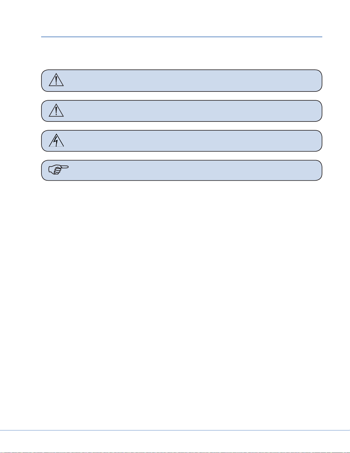
1.4 Table Pinch Points
WARNING To avoid injury to the patient and user, keep fi ngers, hands, and body parts
clear of pinch points.
7
5
1
2
6
4
3
8
9
Figure 1.1 - Pinch Point Locations
15
Page 16
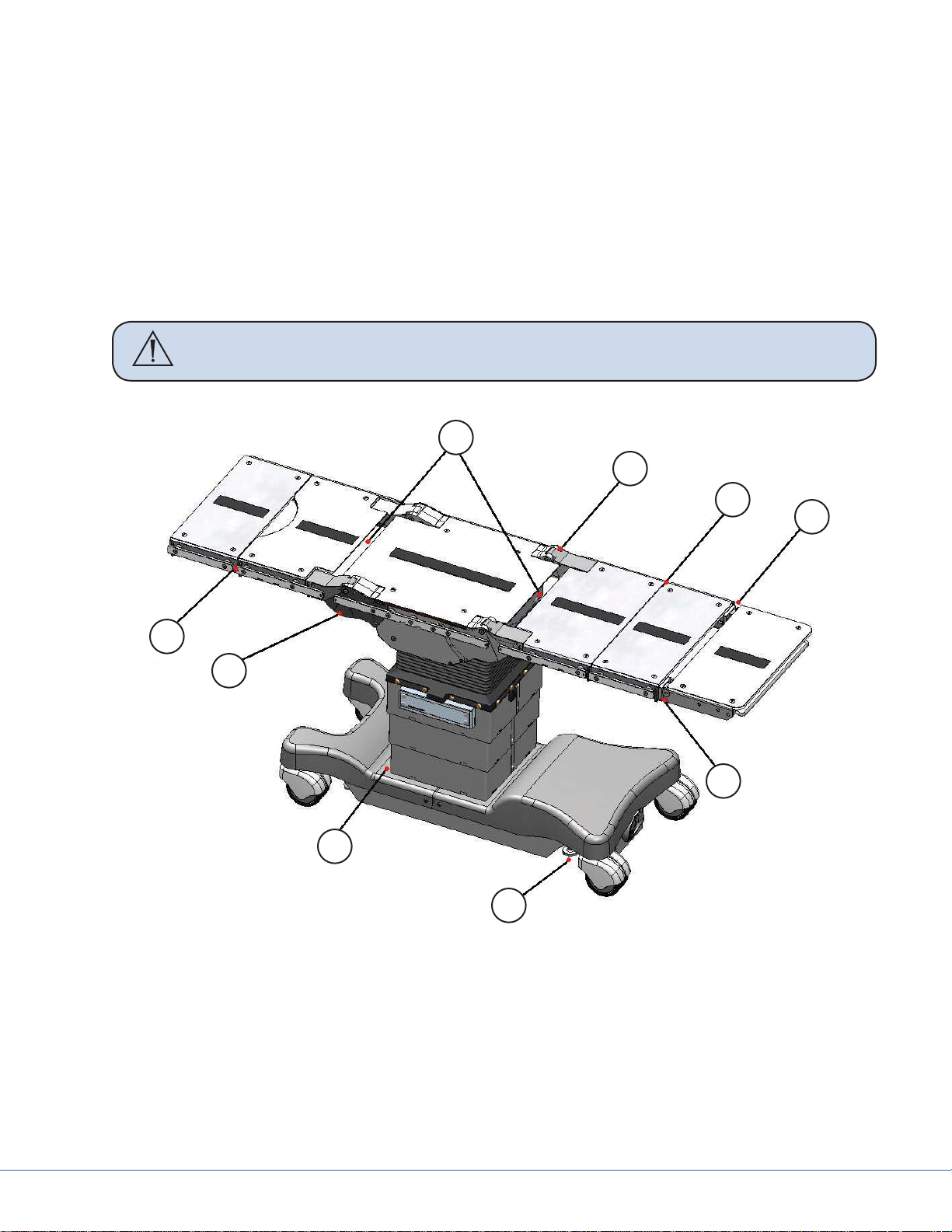
1.4.1 Pinch Point Zones
A pinch point exists at the connection interface
of all modular sections when the sections are attached to each other or to the table.
A pinch point exists on the top edge of both head
rest joints when the head rest is articulated upward. This pinch point also exists when the head
rest is disconnected from the table. Keep fi ngers
and hands clear of this zone at all times. Do not
press the release bar when the head rest is disconnected from the table.
A pinch point exists on the bottom edge of both
head rest joints when the head rest is articulated
downward.
Pinch Points exist under the four articulating
joints of the table behind the joint shields. Do
not put fi ngers or hands underneath the joints of
the table.
A pinch point exists at all four articulating joints
of the table as a gap between the joint and the
main body of the table. Keep fi ngers away from
the articulating joints of the table during movement.
16
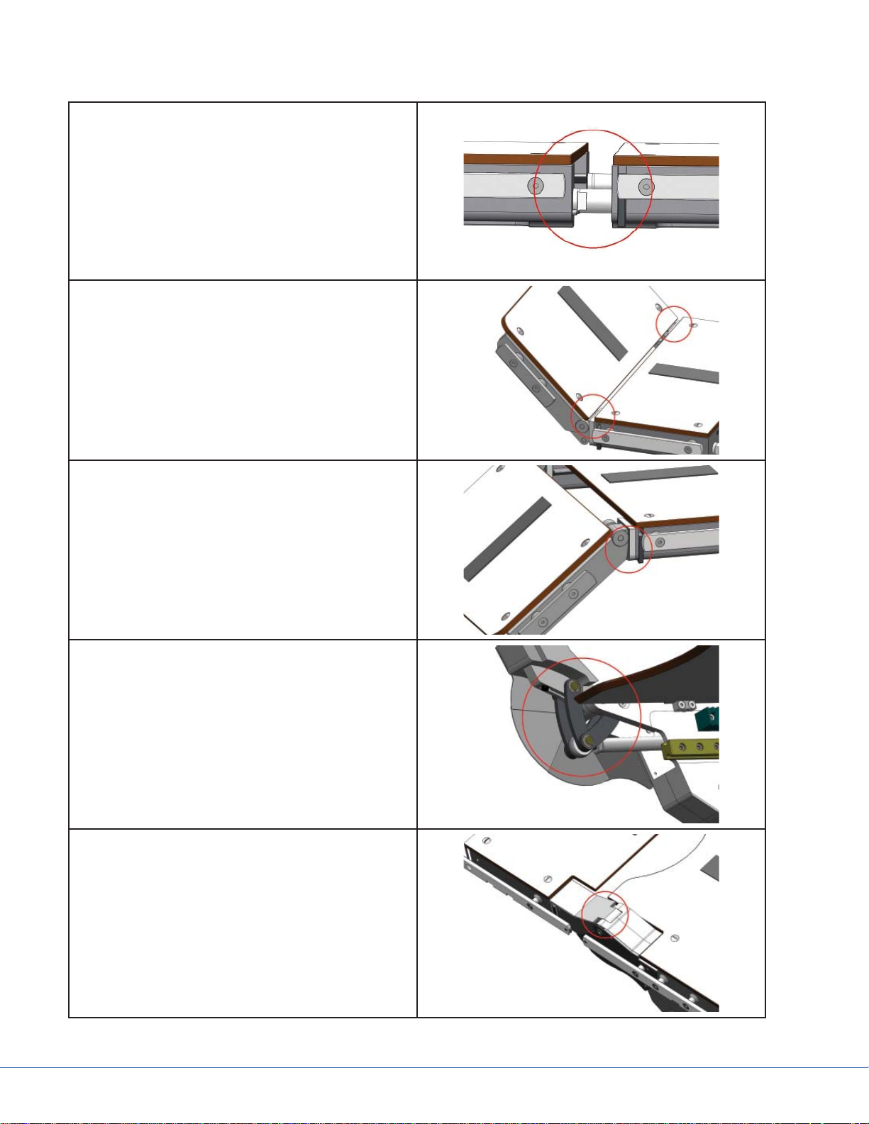
Page 17
Pinch points exist between all accessory rails of
a 25cm section and a 40cm section. Keep fi ngers
and hands clear when connecting a 25cm section
to a 40cm section.
Pinch points exist between the sections and the
column of the table while the table is sliding.
Keep hands and body parts out of this area during articulation of the table.
Pinch points exist under all column casing edges
when it is articulated downward toward the base
of the table.
A crush zone exists beneath all four fl oor locks.
Do not position fi ngers, feet, or hands underneath the fl oor locks.
Pinch points exist on both sides of the table at
the accessory rails when the leg section is articulated downward to the maximum 105°.
17
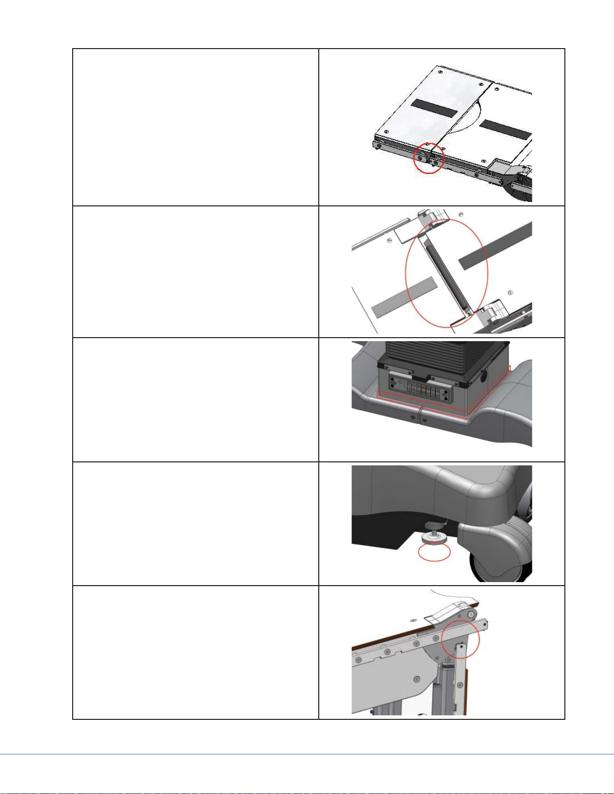
Page 18
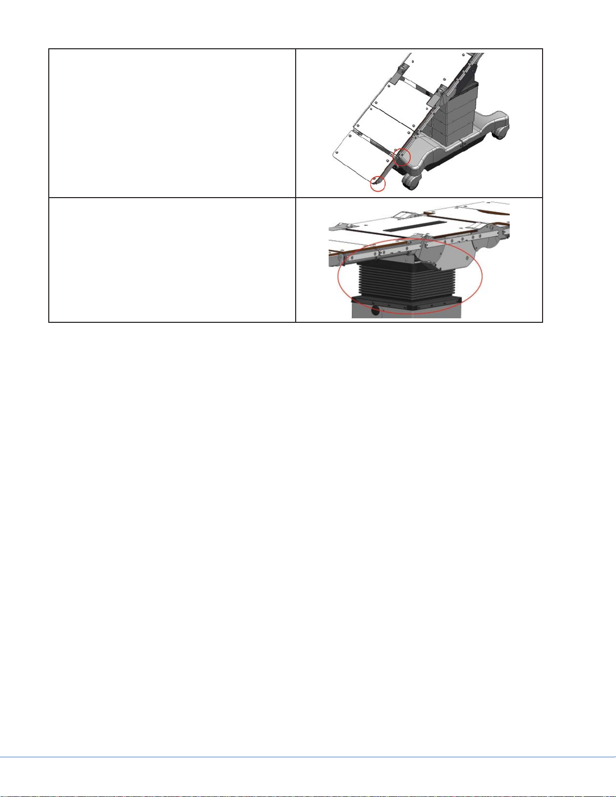
Pinch points exist at any zone where the table top
collides with the base of the table or the fl oor.
Keep all body parts out of these zones when articulating the table.
Pinch points exist inside the fl exible bellows of
the table column. Keep fi ngers and hands away
from the bellows during table articulation.
18
Page 19
2. Product Symbol Defi nition
The following symbols may be found on the Vertier related equipment:
An exclamation mark within a triangle is intended to alert the user to the presence
of important operating and maintenance (service) instructions in the literature accompanying the product.
Denotes the presence of a pinch point.
A lightning bolt within a triangle indicates the presence of hazardous voltage. Refer
all service to authorized personnel.
Denotes earth ground.
Denotes equipotentiality.
Denotes temperature limits.
EDS
(29AZ)
Denotes humidity limits.
Denotes pressure limits.
Denotes a load limitation.
Denote electrical shock hazard.
Denotes oxygen explosion hazard.
Denotes potential electromagnetic interference (EMI).
Denotes usage tips and useful information.
Denotes compliance to European Community Directive 93-42-EEC.
Indicates the product is compliant “Medical Electrical Equipment with Respect to
Electrical Shock, Fire, and Mechanical Hazard only in accordance with UL60601-1.
19
Page 20

(13PZ)
Indicates the product is compliant “Medical Electrical Equipment with Respect to
Electrical Shock, Fire, and Mechanical Hazard only in accordance with UL60601-1,
CAN/CSA C22.2 No601.1.
Indicates hot surfaces.
Denotes compliance to CSA Standard C22.2, 60601.1 - M90, AS 3200, IEC 60601,
IEC 60601-2-46, UL 60601, EN 60601
Denotes the date the equipment was manufactured.
Denotes the manufacturer of the device.
A yellow box with a hand within a triangle is intended to warn the user of the presence of an electrostatic sensitive device. Follow ESD prevention procedures.
Denotes product/part number.
Denotes product/serial number.
Denotes lot or batch number.
Denotes European Representative.
For U.S. audience only - Caution: Federal Law (USA) restricts this device to sale by
or on the order of a physician.
Denotes quantity.
Denotes Class 1 and Type B Equipment.
Class 1 Equipment: equipment in which the protection against electric shock does
not rely on Basic Insulation only, but includes an additional safety precaution in
such a way that means are provided for the connection of Accessible Conductive
Parts to Protective (ground) Conductor in the fi xed wiring of the installation in
such a way that Accessible Conductive Parts cannot become Live in the event of a
failure of the Basic Insulation.
Type B Equipment: equipment is suitable for international external and internal application to the patient excluding Direct Cardiac Application.
20
Page 21
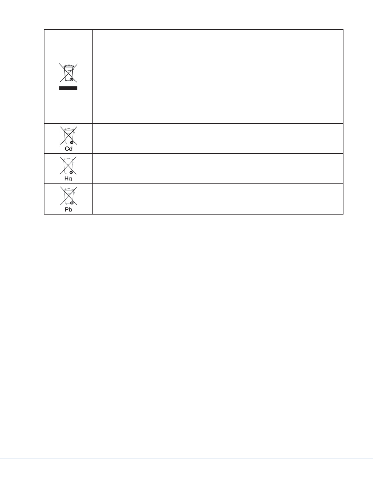
In accordance with European Community Directive 2002/96/EC on Waste Electrical and Electronic Equipment, this symbol indicates that the product must not be
disposed of as unsorted municipal waste but should be collected separately.
Note: The device does not contain any hazardous materials.
Legal regulations may include specifi cations regarding the disposal of this product. We request that you contact Stryker when planning to withdraw this device
from service for discard.
Denotes the device contains more than .002% cadmium.
Denotes the device contains more than .0005% mercury.
Denotes the device contains more than .004% lead.
2.1 EMC Precautions
This device is considered medical electrical equipment and requires special precautions regarding
EMC and needs to be installed and put into service according to the information provided.
Portable and mobile RF communications equipment can affect the performance of this device and
must be used in accordance with the information in this manual.
21
Page 22

Page 23

3. Indications for Use
Stryker conforms to the quality certi cation ISO13485. In addition, the Vertier™ Surgical Table meets
the requirements of UL 60601-1, IEC 601-1-2, and IEC 601-2-46, as certi ed by Intertek ETL Semko.
e Vertier™ Surgical Table is intended for general surgical use. It is also well suited for:
Day surgery•
ENT surgery•
Plastic surgery•
Orthopedics•
Arthroscopy•
Gynecology•
Urology•
Pediatrics•
Neurosurgery•
3.1 Prior to Servicing Tables
WARNING Always wear disposable gloves and a mask when working on used tables
due to a risk of infection or disease. If the table appears to have an excess
of biomaterial, it may need to be cleaned and disinfected the table prior to
service.
Connect to the table via the USB-B service port located at the bottom of the Override Panel. •
See Section 8 for details.
Launch the PC Service software and log into the program; see Section 8 Service Software on •
how to login to the service software.
Verify the Software version. To ensure usage of the most up-to-date version, log on to Agile •
and view Document Number 0100223109. For instructions on how to identify the software/
fi rmware revisions on the table, see Section 8.3 Service Software Identifi cation.
Save the table confi guration data as a safety step in the event that the MPC becomes corrupted •
during service. For instructions on saving the table confi guration data, see Section 8 Service
Software.
View and capture the error data.•
- Go to the Logged Data tab and click on “Read from MPC” and then “Write to File.”
Note The error log can be opened in Notepad or WordPad. Notice the Serial Number
is captured and included at the top of the error log; this will only appear if data
has been read from the MPC as outlined in the above step. This step is very important when error data is sent and analyzed later.
Verify the table functionality before taking any actions; click on the Cycle Test tab. Click on the •
‘Read from File key’ and load the fi le “Test_Cycle_Field”. Remove all sections, pads, and accessories from the table except for the 40CM pelvic extension and the 40CM lower back sections. If the column casings are damaged, remove them and the base covers prior to executing
the cycle test. Ensure the table is free from obstruction and then click on the “Play” button to
execute the cycle test.
23
Page 24

Note If any malfunctions are encountered during this cycle test, investigate and at-
tempt to resolve the issue before proceeding.
Update the MPC software if necessary by going to Agile as specifi ed above and view Document •
Number 0100223108 for the most up-to-date version. For detailed instructions see Section 8.
3.2 Following any Table Service
Verify the Vertier Table Default MPC Settings are correct. Updating software, changing MPC, •
or updating to Sidne™ compatibility can corrupt settings if a problem is encountered during
update. To ensure the settings are correct, go to Agile (For instructions on how to get to Agile
see Section 3.1), retrieve document number 0788307000, compare the default settings to the
actual settings, and make changes as necessary. To make changes, see Section 8 Service Software.
Run the “Test_Cycle_Field” cycle test program on the table again to verify there are no errors or •
malfunctions. See Section 8.7 for details on how to execute this program.
Complete the fi eld service form per SOP1902•
3.3 Operating Characteristics
Vertier™ is a transportable, electrohydraulic battery and Mains operated surgical table. It is •
microprocessor controlled and its function parameters are reprogrammable with a special
PC-operated service program. The table can be connected to 100–240 VAC Mains power, and
its secondary voltage is 24 VDC. The table electronics are safely grounded and it has an equipotential connection.
The table top consists of sliding Seat Section and detachable 25 and 40-sections. The sections •
can be rearranged depending on the surgical concept and operation. The width of the table top
is 540mm, (21 1/4 inches) without rails, and the length is 2100mm (82 inches). The table-top
plate is radiotranslucent material.
Vertier™ can be adjusted with a cable connected Hand Control Unit, an IR Hand Control Unit, •
the foot switch, or through Sidne™. The surgical table can also be adjusted with the Override
Panel in case of electronic malfunction (i.e., if the Hand Control Unit or table microprocessor
becomes defective).
Safe and fault-free use and maintenance of the equipment requires careful adherence to these •
instructions. When mounting accessories to the equipment, the instructions provided with
them must be followed closely. Always keep the instructions for accessories together with this
manual.
24
Page 25
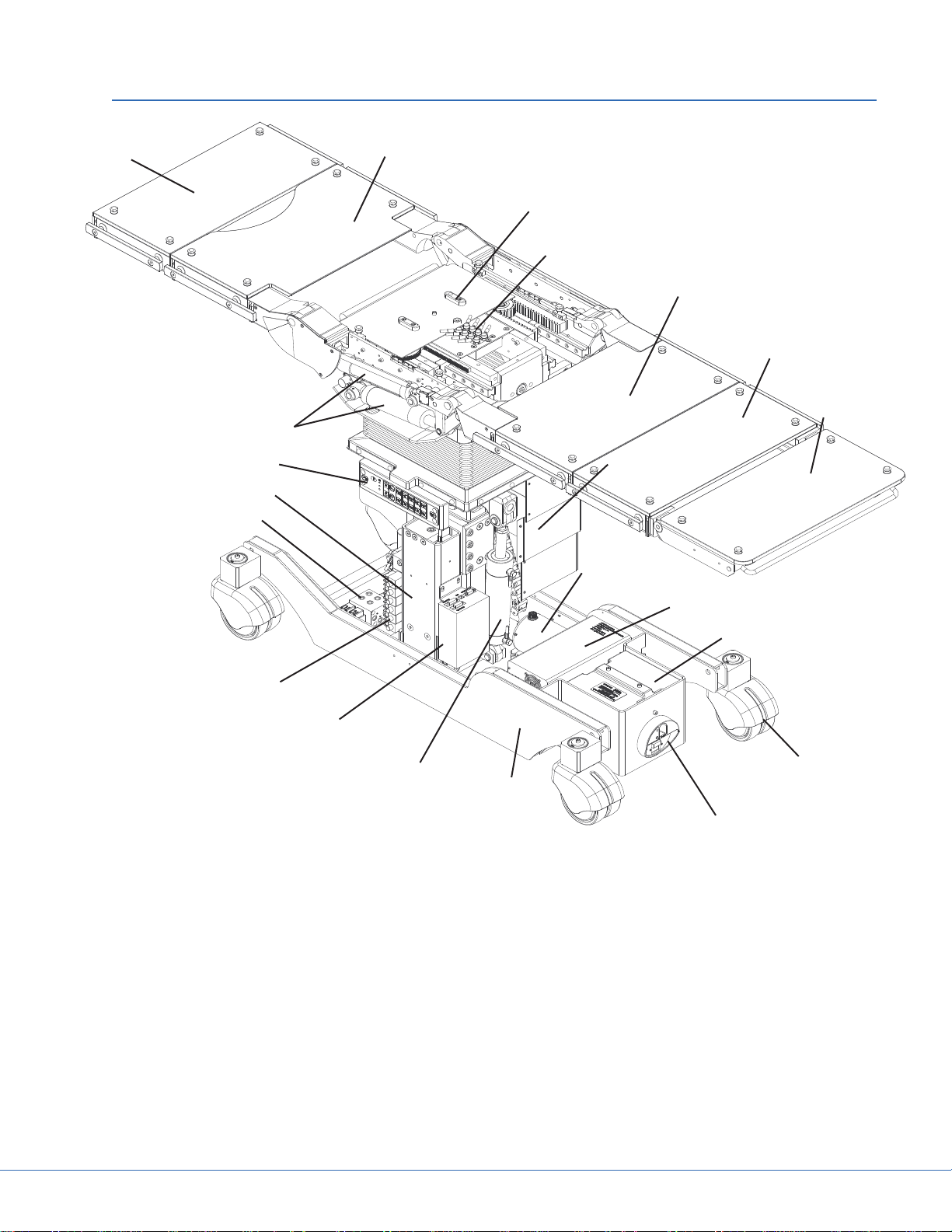
25cm Section
0788300011
4. Main Components Structure
40cm Pelvic Extension Section
0788300004
Seat and Sliding Section
V alve Top Manifold
40cm Lower Back section
0788300008
25cm Section
0788300011
Back and Leg Section
Cylinders
Override Panel
Lifting Column
Floor Lock Valve Block
TLC3 Valve Block
MPC
Cylinder for
Trendelenburg
Head Basic Rest
0788300012
Casing Column
Hydraulic Unit
Power Supply
Battery
Castor
Base Frame
Main Switch, Fuses
and Charging Socket
Figure 4.1 - Main Components Structure
25
Page 26
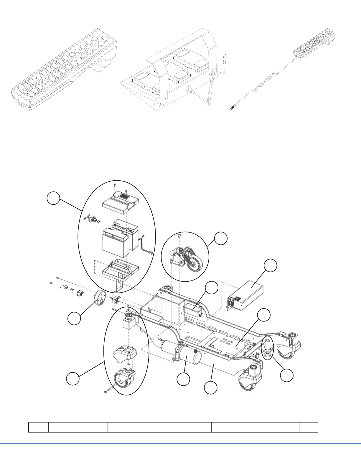
IR-Remote Control
0788305002
Figure 4.2 - Control Devices
4.1 Base and Column Casings
9
Foot Switch Control
0788305005
Sidne™
Remote Control
0788305001
8
6
7
4
5
2
10
3
1
Figure 4.3 - Base
Part Code Part Name Additional Information Qty.
26
Page 27
1 A11533000 Base Frame 1
2 0788300064 Castor Assembly 4
3 0788203000 Hydraulic Unit Assembly 1
4 A11521700 Column Offset Plate 1
5 A1152900 Floor Lock Assembly 1
6 0788205002 Power Charger Assembly 1
7 0788505016 EMI, Filter Unit Medical B-type 1
8 A41763300 5th Wheel Assembly 1
A41767000 5th Wheel Mechanical Parts 1
A41766700 5th Wheel Hydraulic Components 1
9 0788205007 Battery Assembly 1
10 A21549400 Main Switch Panel 1
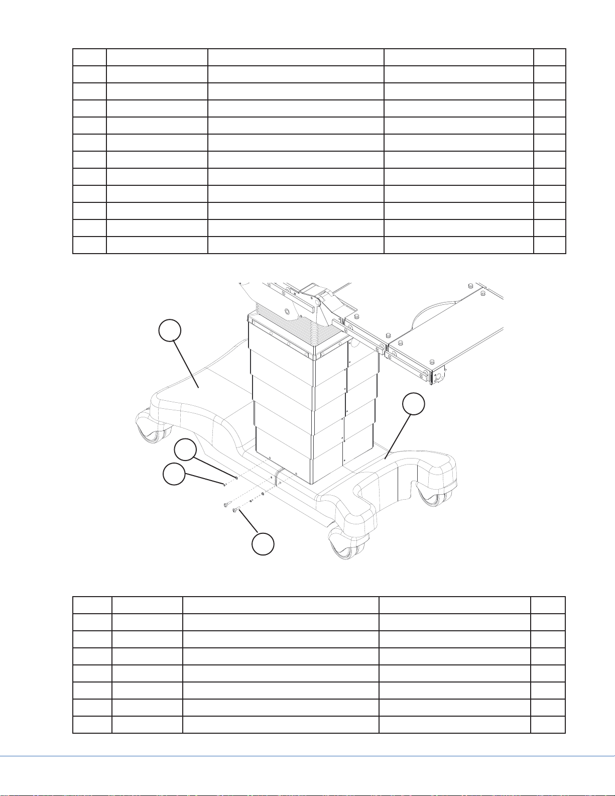
4.1.1 Base Cover Removal
1b
1a
3
2
1c
Figure 4.4 - Table Base Casings
Part Code Part Name Additional Information Qty.
1 0788200000 Base Cover Set Includes items a, b, c, d, and e 1
1a 0788300045 Vertier, Base Cover Leg 1
1b 0788300046 Vertier, Base Cover Back 1
1c 0788300044 Vertier, Base Cover Screw, Plastic Head 4
1d 0788400006 Base Cover Clip Not shown 4
1e 0788400076 Base Cover Hook and Loop Tape Not shown 1
2 0788400004 Column Case-to-Base Screw M4.2X13 A2 F-H DIN 7982 4
27
Page 28
3 0788400025 Machined Column Case-to-Base
Washer
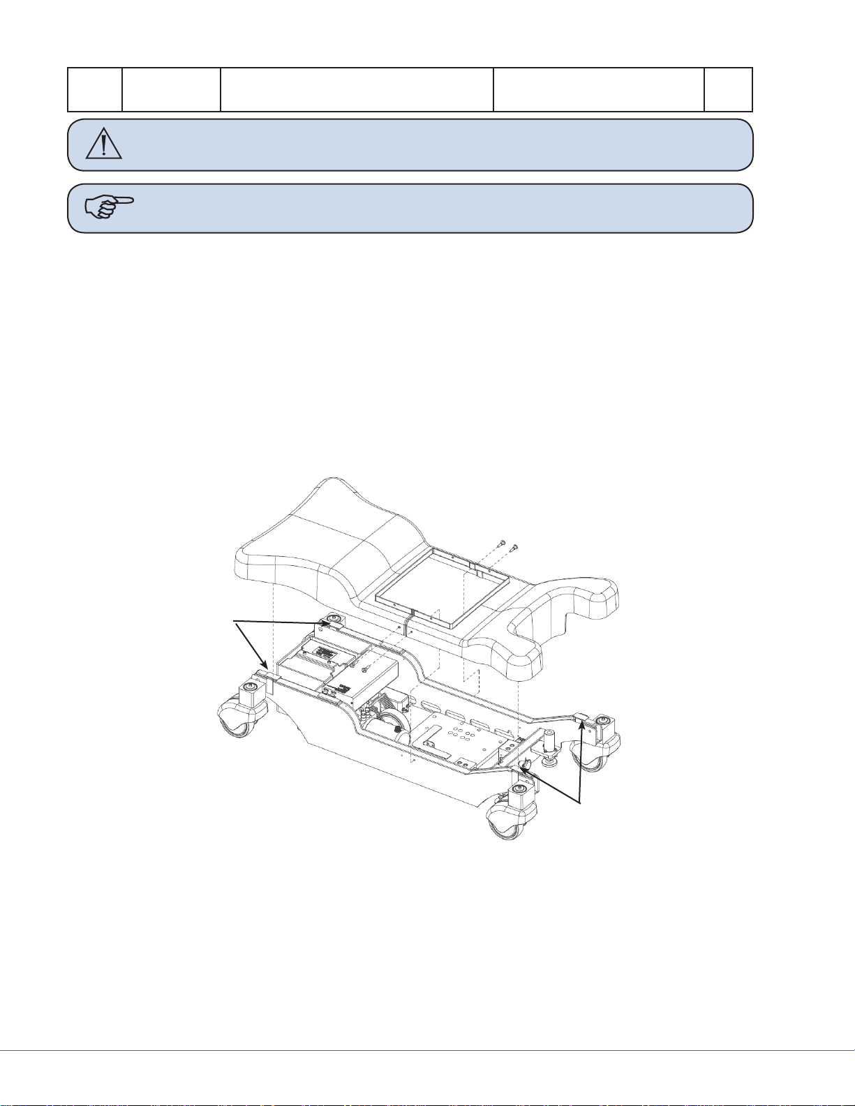
Caution Disconnect the Mains Cord from the table and turn the Main Switch to the
OFF position before removing any base covers.
Note If replacing either base cover, order Base Cover Set 0788200000.
Articulate the table to the highest position.1.
Turn Main Switch to the OFF position and disconnect the Mains Cord.2.
Remove the M4.2X13 column case-to-base screws (Item 2, Figure 4.4) and the machined col-3.
umn case-to-base washers (Item 3, Figure 4.4) from the lowest protective casing shroud.
Remove plastic head screws (Item 1c, Figure 4.4) from both sides of the base covers.4.
Li up the lower column casing shroud slightly and then pull up on the base covers (Items 1a 5.
and 1b, Figure 4.4) to disconnect the hook and loop tape (Item 1e, Figure 4.4).
Pull the base covers toward the end of the table to remove. See Figure 4.5 for the location of the 6.
base cover hook and loop tape.
Repeat steps 1-6 in reverse order to reinstall the base covers.7.
4
Hook and
Loop Tape
Figure 4.5 - Base Cover Removal and Hook and Loop Tape Location
Hook and
Loop Tape
28
Page 29
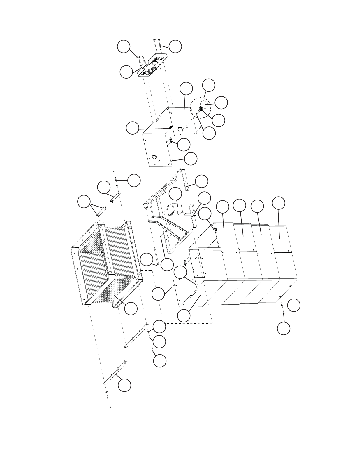
4.1.2 Column Casings
30
28
27
14
4
6
29
25
13
16
12
11
10
9
17
17c
17a
17b
19
20
21
22
7
26
8
18
5
15
3
4
2
1
Figure 4.6 - Column Casing Reference
23
24
29
Page 30

Part Code Part Name Additional Information Qty.
1 0788399014 Bellows Fixing Plate Long 7
2 0788400008 Screw Protecting Cap Black 32
3 0788400032 Plastic Washer 32
4 0788400007 Screw M4X16 ISO 7380 27
5 0788300049 Column Bellows 1
6 0788399013 Bellows Fixing Plate Short 2
7 0788400012 Screw M6X100 DIN 7991 2
8 7105801 Strap 20
9 3761800 Column Casing Spacer 19
10 0788300078 Lower Bellows Frame Right 1
11 0788300079 Lower Bellows Frame Left 1
12 A00767 Compression Nut M3 20
13 3761800 Column Casing Spacer 1
14 A41609500 Hook and loop tape 28
15 A21543500 Casing Half Right 1
16 A41617700 Casing Half Left 1
17 0788205010 IR-Receiver Assembly Includes a, b, and c 2
17a 0788305052 IR ABS Cover 2
17b A41921000 IR PCB 2
17c 0788400084 Fixing Screws M2.5X5 4
18 0788400011 Screw M3X4 Column casing screw 20
19 A21543100 Protective Casing IV 1
20 A21542900 Protective Casing III 1
21 A21542600 Protective Casing II 1
22 A21542300 Protective Casing I 1
23 0788400005 Machined Column Case-to-Base
Washer
24 0788400004 Screw 4,2X13 A2 F-H DIN 7982 4
25 0788399007 Cable Chain Guidance Bracket 1
26 0788400014 Bracket-to-Column Case Screw M3X16 1
27 0788205000 Override Panel Assembly Includes cables 1
28 0788400028 OR Panel Nut Cover 4
29 0788400027 OR Panel Nut M3X15 (5.5MS/NI) 4
4
30 0788400037 Screw M4X6 (located where the
Override Panel wires are
routed)
30
4
Page 31

4.1.2.1 Column Casing Lifted for Base Access
Articulate the table to the highest position.1.
Turn Main Switch to the OFF position and disconnect the Mains Cord.2.
Using a Phillips screw driver, remove the four M4.2X13 column case-to-base screws (Item 24, 3.
Figure 4.6) and machined washers (Item 23, Figure 4.6) that secure the column casings to the
base covers (Figure 4.7).
Gently lift upward on the lower column casing until all of the column casings collapse into the 4.
upper column casing (Figure 4.8).
Figure 4.7
Lift Upward
Figure 4.8
Use bungee cords to secure the column casing in the collapsed position (Figure 4.9).5.
31
Page 32

Figure 4.9
If more access to the lower base frame is needed, the base covers will need to be removed ac-6.
cording to the following steps.
Ensure the Main Switch is in the OFF position and the Mains Cord is disconnected.7.
Remove the plastic head screws from both sides of the base covers (Figure 4.10).8.
32
Figure 4.10
Page 33

Pull up on the base covers to disconnect the hook and loop tape.9.
Pull the base covers toward the ends of the table to remove.10.
Repeat steps 1-10 in reverse order to reattach the base covers and column casings.11.
4.1.2.2 Partial Removal of Column Casings for Access
Note The back side of the table is the side with the Main Switch, and the leg side is the
side with the cutout in the base.
Articulate the table to the highest position.1.
Turn Main Switch to the OFF position and disconnect the Mains Cord.2.
Use a small fl athead screw driver to remove the screw protecting caps (Item 2, Figure 4.6) from 3.
the right casing (Item 8, Figure 4.6).
Using a 2.5mm hex Allen wrench, remove the seven M4X16 screws (Item 6, Figure 4.11) con-4.
necting the right casing half (Item 8, Figure 4.11) to the Bellows Frame.
Using a 2mm hex Allen wrench, remove the M3X16 screw (Item 4, Figure 4.11 and Item 26, 5.
Figure 4.6) that runs through the right casing half (Item 8, Figure 4.11 and Item 15, Figure 4.6)
holding the bracket (Item 25, Figure 4.6) to the right Bellows Frame (Item 10, Figure 4.6). It is
important that this screw be separated for later reinstallation.
Using a 2mm hex Allen wrench, remove the four M3X4 screws (Item 7, Figure 4.11) that join 6.
the right and left casings. The right casing (Item 8, Figure 4.11) can be removed at this point.
Using a 2.5mm hex Allen wrench, remove the two M4X16 screws (Item 5, Figure 4.11) that 7.
secure the leg side of the left casing half (Item 10, Figure 4.11) to the left Bellows Frame (Item
11, Figure 4.6). Using a 2.5mm hex Allen wrench, remove the two M4X16 screws (Item 1, Figure
4.11) that secure the back side of the left casing half (Item 10, Figure 4.11) to the left Bellows
Frame (Item 11, Figure 4.6). Do not remove the two M4X6 screws (Item 3, Figure 4.11) and
the two M4X6 screws (Item 2, Figure 4.11) on the front of the left casing half that are above the
Override Panel.
Flex the left casing half outward in order to lift up on the lower casing sets to disengage the col-8.
umn spacers (Figure 4.12).
Collapse the column casing sets I-IV (Items 19-22, Figure 4.6) all of the way down, until they 9.
are resting on the base covers (Figure 4.13). This allows partial access to all of the column components without fully removing the column casings. For full removal and replacement of the
casings, see Section 4.1.2.3.
To put the column casings back together, repeat steps 1-9 in reverse order.10.
33
Page 34

6
4
8
3
2
10
Figure 4.11 (a) - Screw Locations
6
1
2
3
7
8
7
Figure 4.11 (b) - Screw Locations
5
10
34
Page 35

6
8
7
Figure 4.11 (c) - Screw Locations
5
10
Figure 4.12 - Flex Casing Outward
35
Page 36

Column Casings
I-IV Collapsed
Figure 4.13
36
Page 37

4.1.2.3 Full Removal and Replacement of Column Casings
13
12
10
11
14
6
8
7
5
4
2
1
6
9
3
Figure 4.14 - Column Casing Replacement Set
Part Code Part Name Additional Information Qty.
- 0788200001 Vertier, Column Casings Set Includes items 1-14 below 1
1 A41981500 Column Casing Pair I 1
2 A41981600 Column Casing Pair II 1
3 A41981700 Column Casing Pair III 1
4 A41981800 Column Casing Pair IV 1
5 A41981900 Column Casing Pair V 1
6 A41839800 Spacer with lip 16
7 A41978800 Column Spacer 8
8 A41978900 Column Spacer 8
9 A41784000 Grounding Strip 4
10 0788400011 Column Casing Screw M3X4 20
11 0788400013 Bracket to Bellows Frame Screw M4X8 1
12 0788400014 Bracket to Column Case Screw M3X16 1
13 0788399007 Cable Chain Guidance Bracket 1
14 0788400026 IR Wire Protection Tape 2
Caution Disconnect the Mains Cord from the table and turn the Main Switch to the
OFF position before removing any base covers.
37
Page 38

4.1.2.4 Full Removal and Replacement of Column Casing
Articulate the table to the highest position.1.
Turn the Main Switch to the OFF position and disconnect the Mains Cord.2.
Using a Phillips drive, remove the four M4.2X13 column case-to-base screws (Item 24, Figure 3.
4.6) and machined washers (Item 23, Figure 4.6) that secure the column casings to the base covers (Figure 4.7).
Using a 2.5mm hex Allen wrench, remove the seven M4X16 screws (Item 4, Figure 4.6) connect-4.
ing the right casing half (Item 15, Figure 4.6) to the Bellows Frame.
Using a 2mm hex Allen wrench, remove the M3X16 screw (Item 26, Figure 4.6 and Item 12, Fig-5.
ure 4.14) that runs through the right casing half (Item 15, Figure 4.6) holding the bracket (Item
13, Figure 4.14) to the right Bellows Frame (Item 10, Figure 4.6). It is important that this screw
be separated for later reinstallation.
Using a 2mm hex Allen wrench, remove the four M3X4 screws (Item 10, Figure 4.14) that join 6.
the right and left casings. The right casing (Item 15, Figure 4.6) can be removed at this point.
Using a 2.5mm hex Allen wrench, remove the two M4X16 screws (Item 5, Figure 4.11) that 7.
secure the leg side of the left casing half (Item 15, Figure 4.6) to the left Bellows Frame (Item
11, Figure 4.6). Using a 2.5mm hex Allen wrench, remove the two M4X6 screws (Item 1, Figure
4.11) that secure the back side of the left casing half (Item 16, Figure 4.6) to the left Bellows
Frame (Item 11, Figure 4.6). Do not remove the two M4X16 screws (Item 3, Figure 4.11) and
the two M4X6 screws (Item 2, Figure 4.11) on the front of the left casing half that are above the
Override Panel.
Flex the left casing half outward and lift up on the lower casing sets (Figure 1.12) to disengage 8.
the column spacers (Item 9, Figure 4.6).
Collapse the column casing sets I-IV (Items 1-4, Figure 4.14) all of the way down until they are 9.
resting on the base covers (Figure 4.13).
Starting with casing set IV (Item 4, Figure 4.14), use a 2mm hex Allen wrench and remove the 10.
four M3X4 screws (Item 10, Figure 4.14) that join the right and left casings. The casings can be
rotated 90° to allow better access to the screws. Separate the right and left casing halves of set IV
and remove. The casing sets can now be “peeled” away from the other casing set. Continue this
action to separate and remove the casing sets III-I (Items 1-3, Figure 4.14).
In step 5 the M3X16 screw (Item 12, Figure 4.14) that held the casing, bellows, and bracket 11.
together was removed. Now remove the M4X8 screw (Item 11, Figure 4.14) with a 2.5mm hex
Allen wrench. In order to access this screw, cut the zip tie (Item 1, Figures 4.14 and 4.15) that
secures the OR Panel cables to the white cable clip. Once this screw is removed, cut the zip ties
(Items 2 and 3, Figure 4.16) that secure the guidance bracket (Item 13, Figure 4.14) to the upper
Energy Chain Bracket and the upper Energy Chain, then remove the guidance bracket.
Note This process requires the use of a special 5.5mm thin nut driver tool (Figure
4.18).
38
Page 39

Figure 4.15
1
1
2
3
Figure 4.16
Remove the four grey plastic plugs on the Override Panel (Item 28, Figure 4.17).12.
Using a thin 5.5mm nut driver (Figure 4.18), remove the four nuts (Item 29, Figure 4.17) at-13.
taching the Override Panel to the left upper column casing (Item 16, Figure 4.17) and pull the
Override Panel off of the column casing free from the threaded studs. The Override Panel will
remain suspended by the control cables.
39
Page 40

29
28
16
17b
17c
Figure 4.17 - Override Panel and Column Casing
Figure 4.18 - 5.5mm Nut Driver
Peel back and remove the adhesive covers (Item 14, Figure 4.14) on the back side of the IR sen-14.
sors inside the remaining column casing (Item 16, Figure 4.17). These will be replaced by new
adhesive covers included with the column casing replacement kit (Figure 4.14).
Starting on the inside of the remaining left casing half (Item 16, Figure 4.17), remove the two 15.
small Phillips screws (Item 17c, Figure 4.17) attaching the IR PCB (Item 17b, Figure 4.17) to the
IR plastic lens (Item 17a, Figure 4.17). Do the same for the opposite side.
17a
40
Page 41

1
Figure 4.19
3
2
Use a #1 Phillips drive to remove the M3X6 screw (Item 3, Figure 4.19 [back side is shown]) that 16.
secures the cable clip above the IR Receiver. Be careful not to lose the nut on the inside of the
column casing. Do this for both sides of the column casing.
Use a 2.5mm Allen wrench to remove the cable clip screws (Item 1, Figure 4.20) that secure the 17.
IR cable to the inside of the Bellows Frame. Cut the zip ties (Item 2, Figure 4.20) that secure the
IR cable to the corners of the Bellows Frame. Do this for both sides of the column casing.
2
1
Figure 4.20
Remove the two M4X16 and two M4X6 screws (Items 2 and 3, Figure 4.11) that are located 18.
above the Override Panel, allowing the ability to remove the left half of the column casing pair V
(Item 16, Figure 4.17) from the Bellows Frame.
41
Page 42

The left half of the column casing pair V (Item 16, Figure 4.17) should come free with the plas-19.
tic IR lenses (Item 17a, Figure 4.17) still attached to the casing.
Remove the Phillips screws (Item 2, Figure 4.19) holding the IR lenses to the column casing for 20.
reinstallation on the new column casing set.
To install a new column casing set (Figure 4.14), work in reverse order through the above listed 21.
steps. When installing new zip ties, check that all zip ties are secure and do not pinch the control wires. When installing the new grounding clips (Item 9, Figure 4.14), the corner of the clips
must be bent to allow better seating between the column casing pairs I-IV (Figure 4.21). Install
clips facing outward from column casing pairs I-IV (Figure 4.22). When cycling the column up
and down, the guidance bracket should not noticeably deform, and the Energy Chain should
move freely without stretching or kinking wires. DO NOT crash the upper column casing into
the lower ones if they are partially disassembled.
Figure 4.21
Figure 4.22
Note When replacing damaged column casing sets, examine the Bellows Frames (Items
10 and 11, Figure 4.6 and Items 1b and 1c, Figure 4.23) to ensure there is no
permanent deformation. If these frames are not square, as shown in Section 4.1.3,
they must be replaced. If the Bellows Frames are to be replaced, be sure to transfer
the cable clips onto the new frames from the old frames. Properly secure all cables
prior to reassembly of the new column casings.
4.1.3 Bellows Frame Replacement
42
Page 43

Route hydraulic hoses
through here
4
1c
1b
2
3
1a
Figure 4.23 - Bellows Frame Assembly
Note Bellows frame assembly only includes items 1a, 1b, and 1c.
Part Code Part Name Additional Information Qty.
1 0788200040 Bellows Frame Assembly Includes items 1a, 1b, and 1c 1
1a 0788400012 Bellows Frame Mounting Bolt M6X100 DIN 7991 2
1b 0788300079 Lower Bellows Frame Right 1
1c 0788300078 Lower Bellows Frame Left 1
2 - Hose Retaining Bracket 1
3 - Main Column Spacer 1
4 0788399009 Upper 50mm Energy Chain Guid-
1
ance Bracket
If the Bellows Frames needs to be replaced, fi rst follow the Full Removal and Replacement of the 1.
Column Casings in Section 4.1.2.3.
Unhook the sensor extension wire from the extension wire bracket shown in Figure 4.24. Late 2.
model tables will have the short bracket shown on the right side in Figure 4.23, where older
tables have the long bracket on the left side of the fi gure.
43
Page 44

Tilt the table to the patient left and use bungee cord to secure the Column Bellows (Item 5, Fig-3.
ure 4.6) out of the way to allow for easier access to the two M6 screws (Item 1a, Figure 4.23).
Using a 2.5mm hex Allen wrench, remove the grounding screw (Item 1, Figure 4.25) located 4.
along the right Bellows Frame (Item 1b, Figure 4.23).
Figure 4.24
1
Figure 4.25
Carefully cut away the zip ties that secure the two yellow and green ground wires to the Bellows 5.
Frame (Items 1, 2, and 3, Figure 4.26). New zip ties will need to be placed in these locations
upon installation of the new Bellows Frame.
44
Page 45

1
2
Figure 4.26
Using a 2.5mm hex Allen wrench, carefully remove the cable clip screws (Item 1, Figure 4.27) to 6.
allow for removal of the IR Receiver cables. Cut away any zip ties (Item 2, Figure 4.27) securing
cables to the Bellows Frame. New zip ties will need to be placed in these locations upon installation of the new Bellows Frame.
1
3
2
3
Figure 4.27
Cut the zip ties for OR Panel cables (Items 1 and 2, Figure 4.28). New zip ties will need to be 7.
placed in these locations upon installation of the new bellow frame.
45
Page 46

1
2
Figure 4.28
Note Carefully examine how the hydraulic hoses are routed between the hose retaining
bracket (Item 2, Figure 4.23) and the main column spacer (Item 3, Figure 4.23)
Using a 4mm hex Allen wrench, carefully remove the two M6X100 mounting bolts (Item 1a, 8.
Figure 4.23) that connect the Bellows Frames (Items 1b and 1c, Figure 4.23) and hold the
brackets (Items 2, 3, and 4, Figure 4.23) together to the main column support. Be very careful
to not strip the 4mm hex head key of the M6X100 mounting bolts (Item 1a, Figure 4.23) upon
removal. These screws torque tightly, making them easy to strip and round out. If this happens,
use a screw extractor bit (Figure 4.29) to remove the M6X100 mounting bolt.
Figure 4.29 - Extractor Bit
While the unit is disassembled, refer to Section 12.5 to perform any repairs or maintenance 9.
needed.
To install new Bellows Frame assembly (Item 1, Figure 4.23), work in reverse order through 10.
steps 1-9. Use new zip ties to secure wires and cables as shown in Figures 4.25, 4.26, and 4.27.
46
Page 47

WARNING Ensure that items 2, 3, and 4 in Figure 4.23 are installed in the proper
sequence. Ensure that the lip of the hose retaining bracket (Item 2, Figure
4.23) is pointing up and outward. Failure to do this will cause a hazardous
situation for the patient and user.
4.1.4 Castor Removal
Fixing bolt
M6X12
Figure 4.30
47
Page 48

7
3
11
2
6
5
8
1
4
9
Figure 4.31 - Castor Assembly
Part Code Part Name Additional Information Qty.
- 0788300064 Castor Assembly Includes items 1-11 below 1
1 A31619700 Castor Frame 1
2 71565 Shaft Bearing 2
3 A4445101 Metal Washer 1
4 A41667100 Castor Axel 1
5 0788300047 Castor Cover 1
6 706531 Screw M4X8 DIN 7991 A2 4
10
7 0788400036 Screw M6X12 SFS 2219 1
8 71249 Castor Wheel 2
9 A00873 Wheel Bearing Housing 4
10 707422 Nut M8 A2 DIN 985 2
11 - Plastic Washer 1
48
Page 49

Note THIS IS AN IN-HOUSE FACTORY REPAIR ONLY. Please contact customer ser-
vice for factory repair.
WARNING Before gaining access to remove castors, use the factory table winch to lift
up the surgical table from the ground. Do not attempt without appropriate
factory support equipment for the table.
WARNING Use extreme caution when performing the following sequence of events.
The table is very heavy and can cause serious harm if dropped on the body.
Caution Bearings sit tightly in the base frame—if it is necessary to change them, the
bearing puller may be needed to get them out.
Note Bearings must also be replaced if the castor needs replacement.
Raise the table with the support crane and position it on the high lift pallet jack to gain access to 1.
the castor.
Remove base covers, see Section 4.1.1.2.
Remove the M6 screw (Item 7, Figure 4.31) using a 5mm Allen wrench.3.
The bearings are press fi t into the base frame and cannot be changed without special tools. The 4.
castor frame (Item 1, Figure 4.31) should drop free from the bottom of the base once the M6
screw (Item 7, Figure 4.31) is removed. If this is not the case, a light tapping force can be applied
to the top of the shaft using a brass rod or other soft metal.
Once the castor is free, the four M4 screws (Item 6, Figure 4.31) can be removed with a 2.5mm 5.
Allen wrench such that the castor cover can be replaced.
For bearing removal, use the bearing remover tool (Figure 4.32).6.
Figure 4.32 - Bearing Puller
Once the castor shaft is free and the bearings are still pressed in the base frame, insert the prongs 7.
of the bearing remover along the inside surface of the bearings (Item 2, Figure 4.31 and Figure
4.33).
49
Page 50

Tighten the head of the bearing remover to allow the prongs to expand and grip the bearing 8.
from the inside (Item 1, Figure 4.34).
2
1
Figure 4.33
1
1
Figure 4.34
Pull repeatedly on the handle to dislodge the bearing (Item 2, Figure 4.31 and 4.32) until it is 9.
free (see Figure 4.35).
Caution To avoid damage to the bearing races, ensure that you are pulling the bear-
ing straight out.
50
Figure 4.35
Page 51

To install a new bearing (Item 2, Figure 4.31) use the bearing installer tool shown in Figure 4.36 10.
below.
Figure 4.36 - Bearing Installer
Unscrew the two halves of the bearing installer and place the bearings (Item 2, Figure 4.37) con-11.
centric within the two shafts. The upper half of the bearing installer (Item 1, Figure 4.37) will
have a ½” drive for a socket attachment.
2
2
Figure 4.37
Take the upper half of the bearing installer (Item 1, Figure 4.38) and place it through the top 12.
side of the base frame bearing outlet (not shown).
1
2
3
1
4
Figure 4.38
Take the lower half of the bearing installer (Item 3, Figure 4.38) and place it through the bottom 13.
side of the base frame bearing outlet (not shown).
Align properly so the two halves of the bearing installer are threaded together (Figure 4.38). En-14.
sure that the two bearings (Item 2, Figure 4.38) are concentric to the base frame bearing outlet
(not shown) and to the bearing installer shafts.
51
Page 52

Caution To avoid damage to the bearings and base frame, continually check that the
bearings are straight while tightening the bearing installer.
Attach a ½” drive socket wrench (Item 4, Figure 4.38) and tighten the bearing installer to press 15.
fi t the bearings into the base frame bearing outlet until both the bearings are fl ush.
Once the new bearings are installed, repeat steps 1-4 in reverse order to install a new castor.16.
4.2 Inner Column
upper Energy Chain
Lower Energy Chain
Figure 4.39 - Column
The column includes the bulk of the hydraulic system. Once the column casings are removed, the column is revealed. The main hydraulic valve block with solenoid valves is attached to the column. There
are two Energy Chains to allow for constrained motion of hoses and cables. The tilt, trend and height
cylinders are located here. The height cylinders can not be replaced. The wiring harness is located
directly above the main hydraulic valve block (not shown in Figure 4.39). The wiring diagram can be
found in Section 6. The large metal structure on the top is the tilt frame.
4.2.1 upper Energy Chain Assembly, 50mm (0788-200-038)
52
Page 53

2
6
5
1
3
4
5
Figure 4.40 - upper Energy Chain
Part Code Part Name Additional Information Qty.
- 0788200038 Vertier, upper Energy Chain Assembly, 50mm
1 0788300100 Vertier, upper Energy Chain
(50mm)
2 0788399009 Vertier, Upper 50mm Energy
Chain Guidance Bracket
3 0788399010 Vertier, Lower 50mm Energy
Chain Guidance Bracket
Includes items 1-6 below 1
1
1
1
4 0788400029 M4X6 Socket Cap Screw 2
5 0788400010 M3X8 Socket Cap screw 4
6 0788400030 M3X24 Hex Nut 4
Note Tables with a 40mm Energy Chain can be retrofi tted with the 50mm Energy
Chain Assembly. The 40mm Energy Chain only measures 40mm across and has
the Override Panel cables routed on the outside edge (Figure 4.41).
53
Page 54

1
3
40mm
2
Figure 4.41 - 40mm Energy Chain
4.2.2 Upper 50mm Energy Chain Replacement
Turn the Main Switch to the OFF position.1.
Perform a partial removal of the column casings (see Section 4.1.2.2).2.
Using a 2mm Allen wrench, remove the four M3X8 socket cap screws (Item 5, Figure 4.40) to 3.
disconnect the Energy Chain from it’s upper guidance bracket (Item 2, Figure 4.40) and lower
guidance bracket (Item 3, Figure 4.40).
Caution The socket cap screws (Item 5, Figure 4.40) may be diffi cult to remove. If
they fall into the Energy Chain they must be removed to avoid damage to
the cables and hoses.
Cut the zip ties that secure the 50mm Energy Chain and the guidance brackets (Items 1 and 3, 4.
Figures 4.41, 4.42, 4.43, 4.44, and 4.45) or cut the zip ties that secure the 40mm Energy Chain
and the guidance brackets (Items 2 and 3, Figure 4.41). Note the locations of the zip ties for the
50mm Energy Chain, these will need to be replaced with new zip ties at these exact locations
when the new 50mm Energy Chain is installed.
54
Page 55

Figure 4.42
1
Cut the zip ties that secure the wrapped OR panel cables to the 40mm Energy Chain (Item 1, 5.
Figure 4.41) or the 50mm Energy Chain (Item 2, Figures 4.42, 4.43, 4.44). Note the locations of
the zip ties for the 50mm Energy Chain, these will need to be replaced with new zip ties at these
exact locations when the new 50mm Energy Chain is installed.
1
2
3
Figure 4.43
55
Page 56

1
2
3
Figure 4.44
1
2
3
56
Figure 4.45
Page 57

1
Figure 4.46
Using a 2.5mm Allen wrench, remove the two M4X6 screws (Item 4, Figure 4.40) that secure the 6.
Lower Energy Chain Guidance Bracket (Item 3, Figure 4.40) to the column. This bracket should
have a zip tie on it as shown in Figure 4.47. This helps protect the hoses from its sharp edges.
Figure 4.47
Remove the M3X16 screw that secures the Cable Chain Guidance Bracket to the left Bellows 7.
Frame, as instructed in step 4 of Section 4.1.2.2. Set the screw aside.
57
Page 58

Remove the M4X8 screw (Item 1, Figure 4.15) with a 2.5mm hex Allen wrench. To access the 8.
screw, cut the zip tie (Item 1, Figure 4.15 and 4.15) that secures the OR panel cables to the white
cable clip (Item 1, Figure 4.48).
1
Figure 4.48
Remove the Cable Chain Guidance Bracket (Item 13, Figure 4.14).9.
The upper Energy Chain Guidance Bracket must be removed (Item 2, Figure 4.40). To remove 10.
the bracket, remove the two M6X100 mounting bolts securing the Energy Chain Guidance
Bracket. Refer to Section 4.1.3 to perform this procedure. This will remove the Bellows Frames.
Once all three guidance brackets have been detached, remove all of the electrical wires and hy-11.
draulic hoses from the old Energy Chain (Figure 4.52). Snap out the ends of the Energy Chain
by depressing on the sides (Figures 4.48 and 4.49). The electrical wires and hydraulic hoses can
then be pulled out of the Energy Chain by depressing on the fl ap (Figure 4.51) and sliding the
wire out.
Caution Take care to not tear, kink, or tangle the wires when removing the Energy
Chain.
58
Page 59

Figure 4.49
Figure 4.50
Figure 4.51
59
Page 60

Figure 4.52 - Energy Chain Removed
Before installing the new 50mm chain assembly, sort and group all of the electrical wires and 12.
hydraulic lines in a manner that will prevent them from becoming tangled and crossed when
they are inserted into the new 50mm chain. Tangled and crossed wires may prevent proper
movement and fl exing of the dynamic area of the Energy Chain.
It is recommended that the electrical wires be installed fi rst and a few at a time. Temporarily zip 13.
tie them to the inner wall of the Energy Chain closest to you (Figure 4.53). This will keep them
neatly arranged and out of the way as more wires and hoses are inserted into the Energy Chain.
Install hydraulic hoses in the same fashion. Once all electrical wires and hydraulic hoses are
installed, cut the temporary zip ties.
Caution Keep the wires and hoses from tangling or crossing as much as possible and
removing any temporary zip ties is required to prevent damage to the table.
Install the Override Panel cables into the 50mm Energy Chain. These cables should enter the 14.
Energy Chain at the same level as the Bellows Frame screw holes (Figures 4.44 and 4.45). This
may be adjusted after the guidance bracket is installed. Zip tie override cables to the inside of the
Energy Chain according to Item 2 in Figure 4.45.
60
Page 61

Insert Cables Through Here
Temporarily Zip Tie to Edge
Figure 4.53
Using a 2mm Allen wrench, reattach the 50mm Energy Chain (Item 1, Figure 4.40) to the upper 15.
Energy Chain Guidance Bracket (Item 2, Figure 4.40). Reinstall the Bellows Frames (Section
4.1.3) to secure the upper Energy Chain Guidance Bracket (Item 2, Figure 4.40). Zip tie the
50mm Energy Chain to the upper Energy Chain Guidance Bracket (Item 1, Figure 4.42).
Reinstall the Cable Chain Guidance Bracket to the Bellows Frame (Section 4.1.2.2). Zip tie the 16.
upper Energy Chain Guidance Bracket (Item 2, Figure 4.40), Cable Chain Guidance Bracket
(Item 13, Figure 4.14), and the 50mm upper Energy Chain (Item 1, Figure 4.40) as shown in
Figures 4.42, 4.43, and 4.44.
Using a 2.5mm Allen wrench, reinstall the Lower Energy Chain Guidance Bracket (Item 3, Fig-17.
ure 4.40) to the column. Ensure there is a zip tie installed (Figure 4.47).
Using a 2mm Allen wrench, secure the 50mm chain (Item 1, Figure 4.40) to the Lower Energy 18.
Chain Guidance Bracket (Item 3, Figure 4.40) and zip tie as shown in Figure 4.46.
Ensure that all wires are secured and connected properly, and that all zip ties are tight and fi t 19.
properly. Turn Main Switch to the ON position and cycle the height of the table up and down to
ensure proper dynamic motion of the Energy Chain, zip ties, wires, and hoses. Take care to not
crash the upper column casing into the collapsed column casings on the base.
Turn the Main Switch to the OFF position and reinstall the column casings (Section 4.1.2.2).20.
61
Page 62

4.3 Table Top & Sections
4.3.1 Lever Assembly (0788300067) Replacement/Preventive Maintenance
Figure 4.54 - Lever Assembly
1
2
3
Figure 4.55 - Lever Assembly Detail
Loosen the threaded pin (Item 1, Figure 4.55) with a fl at head screw driver.1.
Apply pressure to the side of the lever (Item 2, Figure 4.55) to keep the spring tension off of the 2.
pin. Pull the threaded pin (Item 1, Figure 4.55) out of the extrusion. This may require pliers.
Carefully remove the lever and spring (Item 3, Figure 4.55). 3.
Inspect all components and the slot in the extrusion for damage.4.
62
Page 63

Normal wear may result in burns on edges. File away any sharp edges on the lever or in the slot. 5.
If necessary, replace the lever with a new assembly.
Lubricate the lever spring pin and slot with light machining oil.6.
WARNING The spring is under compression, use caution when removing the lever.
To reassemble, the spring (Item 3, Figure 4.55) must be placed in the hole in the slot on the side 7.
of the extrusion fi rst and held under compression with the lever (Item 2, Figure 4.55) while the
threaded pin (Item 1, Figure 4.55) is loosely fi t into the hole from the front.
Once the pin has been loosely fi tted, it can be threaded into place while applying light pressure 8.
to the side of the lever as needed.
Check function.9.
4.3.2 Threaded Lever Spring (0788400000) Replacement
2
4
1
Figure 4.56 - readed Lever Spring
The threaded lever spring (Item 1, Figure 4.56) is held in place by a slight mechanical interfer-1.
ence; however, it can be unthreaded and replaced using an M5 spring plunger wrench (Item 2,
Figure 4.56). If the plunger sticks, replace the threaded lever spring.
If the pin is broken, remove the remainder of the threaded pin with pliers or a screw extractor.2.
Caution DO NOT USE Loctite or other glues to hold the spring in place.
Install the new lever spring by threading it into the hole with the spring plunger wrench. The 3.
top of the spring housing (Item 3, Figure 4.56) should be slightly lower than the back edge of
the groove in the pin.
Attach the section to test to ensure the pin works properly. If the lever is too diffi cult to pull out, 4.
thread the spring in further. If the lever will not stay out or can be pushed in by hand, thread the
spring out.
It is possible to lock the pin into place using a punch at the base of the threads. This should me-5.
chanically lock the threads to prevent it from moving.
3
4.4 Seat Section and Assemblies
63
Page 64

To gain access to the center section of the table, the Seat Section Plate must be removed by loosening
the four M10X25 (Figure 4.57) bolts using a large fl at driver socket.
Caution Any time the Seat Section Plate is removed, make sure the hoses and cables
are not routed over spacers or routed improperly. See Figure 4.58 for the
proper confi guration.
Figure 4.57
Figure 4.58
64
Page 65

12
4
5
3
Figure 4.59 - One Piece Seat Section
Part Code Part Name Additional Information Qty.
1 0788300085 Vertier Seat Plate 1
2 0788400001 Top Plate Screw AISI 303 M10X25mm 4
3 0788200015 Vertier Seat Section Rail Assy AISI 304 (US) 2
4 0788400019 Accessory Rail Bushing 6
5 0788400009 Accessory Rail Screw M8X40 DIN 7991-A2 6
65
Page 66

2
1
3
4
5
Figure 4.60 - Two Piece Seat Section
Part Code Part Name Additional Information Qty.
1 0788300085 Vertier Seat Plate 1
2 0788400001 Top Plate Screw AISI 303 M10X25 4
3 0788400019 Accessory Rail Bushing 10
4 0788200039 Vertier Two Piece Seat Section
Rail Assembly
5 0788400009 Accessory Rail Screw M8X40 DIN 7991-A2 10
2
66
Page 67

4.4.1 Center Rail Section
9
1
8
10
6
5
12
13
11
15
Figure 4.61 - Center Rail Section
Part Code Part Name Additional Information Qty.
1 A41770600 Seat Section Cover 1 1
2 A41770100 Seat Section Cover 2 1
14
3
4
2
7
16
3 0788300103 Seat Section Slider, Long 2
4 0788400036 Slider Fixing Screw M6X12 SFS 2219 4
5 0788300104 Seat Section Slider, Round 2
6 0788400036 Slider Plug Screw M6X12 SFS 2219 2
7 0788400067 Cover Fixing Screw M5X10 ISO 7380 4
8 0788400044 Screw M6X12 1
9 0788400086 Cable Support DIN 914 M5X6 1
10 A41808500 Distribution Block 1
11 0788300066 Sledge Assembly Right 1
12 0788300065 Sledge Assembly Le 1
13 A11529400 Tilt Frame 1
14 A11538900 Upper Fixing Frame 1
67
Page 68

15 A31615000 Slide Motor Assembly 1
16 0788205008
0788205009
4.4.2 Tilt Frame Assembly
1
28
Safety Edge Sensor Assembly Bullet crimps
Quick connect
22
2
4
5
3
7
8
25
10
6
13
12
21
9
15
14
20
16
2
2
24
23
29
27
Figure 4.62 - Tilt Frame Assembly
Part Code Part Name Additional Information Qty.
1 706411 Screw M8X70 SFS 2219 1
2 A41621800 Cardan Sha 1
3 A41621700 Slide Bearing IGUSGFM-2023-21 1
4 A41621600 Slide Bearing IGUSGTM2036-015 1
5 0788400071 Screw M10X20 8.8ZN DIN 7991 2
6 A41887400 Limiter 10 104029-103-15 2
7 0788400079 Circlip 14X1 DIN 471 2
8 0788300108 Narrow Tilt Axle 1
9 0788400059 Screw M5X30 SFS 2219 6
10 0788400080 Circlip 8X0.8 AISI DIN 471 1
11 A41620200 Joint Pin 104029-111-02 2
12 A41620300 Slide Bearing IGUSGSM-0810-08 2
26
11
17
18
30
19
68
Page 69

13 0788400060 Screw M6X25 SFS 2219 2
14 0788300109 Slide Bearing GSM-1416-22 2
15 0788400059 Screw M6X30 SFS 2219 2
16 0788400059 Screw M6X30 SFS 2219 4
17 708187 Cylindrical Pin 8X30 M6 DIN7 4
18 A41887500 Limiter 18 2
19 0788400071 Screw M10X0 8.8ZN DIN 7991 2
20 A31610300 Rack Bar 10X10/9 M=1 1
21 A41884500 Guide Rail THK 25 400 LH, Le 1
22 0788400061 Screw M6X30 SFS 2219 13
23 A41683000 Shield Plate Le 1
24 A41682900 Shield Plate Le 1
25 A41948100 Rack Bar 30X25/22 M=3 1
26 A41884500 Guide Rail THK 25 400 LH, Right 1
27 0788400061 Screw M6X30 SFS 2219 13
28 A41674300 Shield Plate Right 1
29 A41674400 Shield Plate Right 1
30 A11538900 Tilt Frame Lower Parts Assembly 1
69
Page 70

4.4.3 Tilt Frame Lower Parts Assembly (view from underside)
5
6
7
8
2
9
Figure 4.63 - Tilt Frame Lower Assembly ( gure inverted for visibility)
Part Code Part Name Additional Information Qty.
1 A31615000 Fixing Frame for Bellow 1
2 A31610900 Protecting Cover A4182500 1
3 0788400067 Screw M5X10 A2 ISO 7380 7
4 0788305012 Tilt/Trend Gravity Sensor 1
5 0788400041 Screw M4X6 DIN 7984 2
6 0788400022 Zip Tie - Long TY28 MX, black 6
7 0788400041 Screw M4X6 DIN 7984 6
8 0788400020 Plastic Bracket ELFA 55-032-71 6
9 0788400067 Frame Fixing Screw M5X10 A2 ISO 7380 4
4 3
1
4.4.4 Slide Motor Assembly
70
Page 71

12
14
16
13
10
21
17
15
9
22
11
18
25
23
24
20
26
37
36
2827
30
34
32
35
33
31
4
3
1
Part Code Part Name Additional Information Qty.
1 480242 Circlip D5 DIN 6799 1
2 A41622100 Needle Bearing SKF NKI 7-16 1
3 A31610800 Trapezoid Screw 104029-103-04 TR16X4 1
4 A31610000 Bracket for Trapeziod Screw 104029-103-02 1
5 0788400063 Screw M10X30 SFS 2219 2
6 480100 Screw M3X20 DIN 7985 1
7 0788400082 Nut M3 SFS 2067 1
8 A41619600 Nut Block for Trapeziod Screw 1
9 A41619400 Slide Crank Block 10 X16X0.5 DIN 988 1
10 70597 Hex Screw M10X20 SFS 2064 1
11 A31610500 Idler Pulley Assembly 104029-107-00 1
12 70731 Nut M8 SFS 2068 1
13 A41623600 Drive Sha 104029-106-02 1
14 A41623500 Slide Bushing 104029-106-04 1
15 A41643800 Circlip 16X1 V-RING 5008 1
16 A41623700 Ball Bearing SKF 618-8 1
17 A41623400 Gear Wheel 1
18 A41643900 Wedge Piece 4X4/18 DIN 6885A 1
19 0788305013 Voltage Pot Slide WPS-250 1
2
8
7
6
Figure 4.64 - Slide Motor Assembly
5
19
29
71
Page 72

20 A41622600 Gear Wheel 104029-103-03 1
21 0788305027 Slide Motor GR53X58 U=24V WITH SG62
I=15
22 706791 Retaining Screw M5X12 DIN 915 1
23 0788400003 Cogged Belt 171 352 00 1
24 7043431 Motor Fixing Screw M3X10 A2 ISO 7380 4
25 0788400062 Screw M8X16 SFS 2219 4
26 A31610700 Motor Fixing Plate 104029-100-11 1
27 0788400057 Hex Screw M10X30 ZN DIN 933 2
28 A31609900 Trapeziod Screw Fixing Block 1
29 0788400040 Sensor Fixing Screw M2.5X25 DIN 7985 3
30 A41622300 Ball Bearing SKF 6000-2RS1 1
31 A41622400 Fitting Ring 10X16X0.5 DIN 988 1
32 A41622300 Ball Bearing SKF 6000-2RS1 1
33 A41622000 Bushing 104029-103-06 1
34 A41634700 Circlip 26X1.2 DIN 472 1
35 707781 Support Plate M8 DIN 125 1
36 70731 Nut M8 SFS 2068 1
37 70731 Nut M8 SFS 2068 1
1
72
Page 73

4.4.4.1 Slide Motor Belt Lubrication and Tension Adjustment
Detach any leg sections that may be currently attached to the table.1.
Use slotted socket or screwdriver to remove the four M10X25 screws (Item 1, Figure 4.65) secur-2.
ing that top seat plate. Remove the top seat plate.
1
Figure 4.65
Using two zip ties, secure the two Seat Section Sensor cables to the side rails so they are out of 3.
the way of the slide rack and pinion mechanisms (Item 1, Figure 4.66). If these are not secured
in this manner, they could be crushed by the gears within the slide rack and pinion mechanisms
when the cover plate is removed and the table slide is articulated.
Caution If cables are not secured out of the way, they can be crushed between the
rack and pinion, which will damage the MPC.
1
1
73
Page 74

Using a 5mm hex Allen wrench, remove the fi ve M6X12 screws (Item 1, Figure 4.67) that secure 4.
the leg side cover plate (Item 2, Figure 4.67) and the leg section sliders (Item 3, Figure 4.67).
Use a 3mm hex Allen wrench to remove the two M5X10 cover screws (Item 1, Figure 4.68) that
secure the leg side cover plate.
Remove the leg side cover plate and disconnect the Safety Edge Sensor (Item 1, Figure 4.69).5.
Figure 4.66
1
1
3
1
Figure 4.67
1
2
74
Figure 4.68
Page 75

Caution To avoid damage to the Safety Edge Sensor wires, ensure that they are not
crushed between the cover plate and table upon reinstallation.
1
Figure 4.69
Note Older tables have two bullet crimp connectors for the Safety Edge Sensor.
Use Vaselinspray or light machine oil to lubricate the slide belt pulley bearings. Ensure nozzle is 6.
attached to Vaselinspray for easier delivery of lubricant to bearings (Item 1, Figure 4.70). Lubricate the bearings on the front and back sides of the pulleys (Item 5, Figures 4.71 and 4.72).
Three of the pulleys are located directly behind the Slide Motor Bracket (items 1-3, Figures 4.71
and 4.72). To gain access to the fourth pulley (Item 4, Figures 4.71 and 4.72), proceed to step 7.
75
Page 76

1
2
Figure 4.70
1
5
3
4
5
Figure 4.71
76
Page 77

5
4
Ensure that at least one section is attached to the head side of the table.7.
Slide the table all of the way in the head direction and raise the leg joints to the maximum up-8.
ward position. Using a 2.5mm Allen wrench, remove the four screw caps and the four M4X16
screws (Item 1, Figure 4.73). You may need to remove the two screw caps and loosen the two
M4X16 screws (Item 2, Figure 4.73) to allow for greater access.
13
Figure 4.72
11
12
15
2
1
Figure 4.73
Pull down the rubber bellows to gain access to the inside corner of the tilt frame. The fourth 9.
pulley is located here (Item 1, Figure 4.74) and the bearings can be lubricated from the front
and the back of the pulley (Item 2, Figure 4.74). Ensure that the bearings in the housing next to
77
2
Page 78

the back of the pulley also get lubricated.
2
1
Figure 4.74
Note If lubrication does not fi x the squeaking or abnormal movement, the belt tension
can be adjusted to reduce noise and uneven movement.
To adjust tension on the slide belt, insert a 4.5mm Allen wrench into one of the slotted holes of 10.
the belt tension pulley adjuster (Item 1, Figure 4.75). While securely holding the Allen wrench
(Item 1, Figure 4.76), use a 17mm open face wrench (Item 2, Figure 4.76) to break loose the bolt
on the back side of this tension pulley adjuster. Break this bolt just loose enough for the belt tension pulley adjuster to be free to adjust the belt tension pulley.
Use your fi nger to gage the tightness of the slide belt. The slide belt can be between 1-2mm 11.
when pressed by a fi nger (Figure 4.77). It is important for the slide belt to not be too tight or
loose on the pulleys.
2
78
Page 79

Figure 4.75
1
1
Figure 4.76
2
79
Page 80

Figure 4.77
Tighten the tension pulley back up using the 17mm open face wrench on the bolt (Item 2, Fig-12.
ure 4.76). The Allen wrench (Item 1, Figure 4.76) must be inserted into one of the belt tension
pulley adjuster slots (Item 1, Figure 4.75) to hold its position while the bolt is being tightened.
After the bolt and tension pulley are tightened into place, recheck the belt to ensure the tension
is the same as described in step 11 (Figure 4.77).
Repeat steps 1-12 in reverse order to reassemble.13.
4.4.4.2 Replacing the Slide Motor and Drive Belt
If only the slide motor needs to be changed, skip steps 15-26.
Note See Section 6.19.2 for replacement of the Slide Motor-to-MPC Cable.
Note For instruction clarity, the Seat Section side beams have been removed in some of
the pictures shown in this section. These do not need to be removed to perform
the outlined procedure.
Switch the table to the OFF position, and unplug the Mains cable.1.
Remove the seat plate (see Section 4.4).2.
Remove the rubber bellow from the upper fi xing screws (Figure 4.78). Move the Seat Section 3.
beams so that all fi xing screws can be reached. If the slide motor is unable to move the Seat Section, leave the screws on the right side of the rubber bellows (Figure 4.79).
80
Page 81

Figure 4.78 Figure 4.79
Remove the shield plates from Seat Section (Figure 4.80). It is necessary to remove the spacers 4.
and screws (Items 3-8, Figure 4.61). The Safety Edge Sensors must be disconnected to completely remove the shield plates.
Caution When reinstalling the shield plates, ensure that the Safety Edge Sensors are
connected and not crushed between the shield and table.
Caution Take care to prevent damaging the wires and hoses.
Caution If the white column sealing gasket or column sealing bracket are damaged,
replace them per section 4.4.15.
Figure 4.80
Remove the frame attaching screws (Item 3, Figure 4.63 and Figures 4.81, 4.82, 4.83, and 4.84). 5.
81
Page 82

Cut the cable ties around the motor connectors (Figure 4.83).6.
Figure 4.81 Figure 4.82
Figure 4.83
Unplug the motor’s connectors.7.
Caution Take care to prevent damaging the motor and slide position sensor wires
(Figure 4.84).
Figure 4.84
Carefully let down the frame (Figure 4.85). Move frame under the motor end.8.
82
Page 83

Figure 4.85
If the slide motor or drive belt are unable to move the Seat Section side, rotate the drive shaft 9.
with a socket wrench (fi gure 4.86). Movement will only be possible if the belt is broken. If the
belt needs to be replaced, the old belt may be cut away to allow shaft rotation (Figure 4.87).
Remove the stop plates from the motor end of the Seat Section (Item 18, Figure 4.62 and Figure 10.
4.88).
Loosen the belt tensioner (Item 11, Figure 4.64 and Figure 4.89).11.
Figure 4.86 Figure 4.87
Figure 4.88
83
Page 84

Remove the attaching screws from the motor frame (Item 25, Figure 4.64 and Figure 4.90).12.
Figure 4.89
Figure 4.90
Pull the motor assembly straight out (Figure 4.91), taking care not to drop the key from the mo-13.
tor shaft and to keep from bending the shaft while removing the assembly.
Figure 4.91
Detach the position sensor screw (Item 6, Figure 4.64) from the slide nut (Item 8, Figure 4.64 14.
and Figure 4.92).
84
Page 85

Remove the bolts (Item 27, Figure 4.64) from the trapeze shaft bearing housing (Item 28, Figure 15.
4.64 and Figure 4.93).
Figure 4.92
Pull out the trapeze shaft and housing from the other end bearing, taking care not to damage 16.
the position sensor while doing so.
Remove the belt from the pulleys and slide the belt over the trapeze shaft end (Figure 4.94).17.
Place the new belt over the trapeze shaft.18.
Insert the trapeze shaft end back into the end bearing housing (Item 4, Figure 4.64).19.
Place the new belt around the pulleys (Figure 4.95).20.
Figure 4.93
Figure 4.94
85
Page 86

Attach the bearing housing bolts (Item 27, Figure 4.64) to the bearing housing (Item 28, Figure 21.
4.64).
Align the bearing housing (Item 28, Figure 4.64) so that it is parallel to the Seat Section frame 22.
(Figure 4.96).
Figure 4.95
Make sure the slide nut fi ts into the right place in the slide mechanism.23.
Attach the position sensor’s wire back to the slide nut (Figure 4.97).24.
Attach the motor assembly to the Seat Section frame and tighten the bolts.25.
Adjust the tension of the belt by pressing it between the pulleys until the belt only moves 26.
2-3mm (Figures 4.98 and 4.99).
Figure 4.96
Figure 4.97
86
Page 87

Figure 4.98 Figure 4.99
The Slide Motor’s output shaft and the fi rst pulley must be concentric. If they are misaligned the 27.
slide motor will be noisy. A misaligned motor can cause damage.
The only way to determine if the alignment is correct is to drive the motor and listen to the 28.
sound.
Make sure all wires are connected and then switch the power ON.29.
Make sure there are no hoses, wires, etc. in the slide mechanism.30.
To adjust the Vertical alignment, loosen the bolts and move the motor assembly up or down and 31.
listen to the sound of the motor.
To adjust the horizontal alignment, loosen all of the bolts and then retighten, starting with the 32.
right side and then the left. The assembly will move slightly horizontally, depending on which
side the bolts were tightened on fi rst. Continue adjusting the bolts until there is no noise from
the motor.
Figure 4.100
Reassemble all removed parts.33.
Make sure the motor’s electrical wire is secure.34.
Test drive the slide movement and all other table functions.35.
4.4.5 Right Sledge Assembly (0788-300-066)
87
Page 88

18
10
9
13
8
5
1
3
7
6
4
2
Figure 4.101 - Right Sledge Assembly
16
14
17
15
12
11
Part Code Part Name Additional Information Qty.
1 A41884500 Guide Post AMT MSA 25 R400-20/20H 1
2 A41886100 Sledge AMT MSA 25 2
3 41680200 Screw M8X16 SFS 2219 2
4 7081874 Cylindrical Pin 8X20 H9 ISO 2338 4
5 A41688800 Fixing Plate Right 1
6 A41674700 Sha Pin 1
7 0788400050 Circlip 32X1.2 DIN 472 1
8 A41625100 Bearing SKF 6002-2RS1 2
9 A41624900 Gear Wheel MÄDLER 243 820 00 1
10 0788400046 Circlip D16X1 DIN 471-AISI 1
11 0788400044 Screw M6X12 DIN 7991 8
12 0788400064 Screw M6X20 DIN 7991 4
13 A41672000 Fixing Plate Right 1
14 0788400044 Screw M6X12 DIN 7991 8
15 A41680400 Sliding Pin 6
16 A41730100 Fixing Plate Right 1
17 A41886100 Sledge AMT MSA 25 2
18 A41884500 Guide Post AMT MSA 25 R400-20/20 1
4.4.6 Left Sledge Assembly (0788-300-065)
88
Page 89

17
16
15
9
12
8
6
1
Part Code Part Name Additional Information Qty.
1 A41884500 Guide Post AMT MSA 25 R400-20/20 1
2 A41886100 Sledge AMT MSA 25 S 2
3 41680200 Screw M8X16 SFS 2219 2
4 7081874 Cylindrical Pin 8X20 H9 ISO 2338 4
5 A41674700 Sha Pin 1
6 A41688900 Fixing Plate Le 4
7 A41625200 Bearing SKF 6002-2RS1 2
8 0788400050 Circlip 17X1 DIN471 4
9 A41625300 Gear Wheel MÄDLER 214 990 80 6
10 0788400044 Screw M6X12 DIN 7991 8
11 0788400064 Screw M6X20 DIN 7991 4
12 A41680500 Fixing Plate Le 1
13 0788400044 Screw M6X12 DIN 7991 8
14 A41680400 Sliding Pin 6
15 A41680900 Fixing Plate Le 1
16 A41886100 Sledge AMT MSA 25 2
17 A41884500 Guide Post AMT MSA 25 R400-20/20 1
7
5
4
3
2
Figure 4.102 - Le Sledge Assembly
10
11
13
14
4.4.7 Left Seat Section Tube - One Piece
89
Page 90

7
8
5
4
2
3
6
10
9
1
Figure 4.103 - Le Seat Section Tube
Part Code Part Name Additional Information Qty.
1 70625 Screw M6X20 SFS 2219 13
2 A41622700 Guide Post THK 25 400 LH 1
3 A31610300 Gear Rack 1
4 0788400064 Screw M6X20 DIN 7991 4
5 A41627600 Plate Fixing Part 2
6 708188 Cylindrical Pin M6 4X12 DIN 7 6
7 0788400065 Screw M4X12 DIN 7984 2
8 A41653700 Hydraulic Hose Guide 1
9 0788400058 Screw M5X20 SFS 2219 5
10 7081872 Cylindrical Pin M6 4X20 DIN 7 2
11 A41628900 Level Rod 104029-103-14 1
12 A41712300 Seat Section Tube Le 1
11
12
90
Page 91

4.4.7.1 Left Seat Section Tube - Two Piece
9
11
12
13
5
3
1
5
6
7
8
9
9
7
24
14
3
15
16
9
17
18
3
4
6
8
Figure 4.104 - Le Seat Section Tube
Part Code Part Name Additional Information Qty.
1 A41824500 Le Tube Outside Half 1
2 A41819300 Le Tube Inside Half 1
3 A41823800 Joint Pin 16mm 4
4 A41823900 Joint Pin 12mm 2
5 A41834100 Bushing 2
6 0788400069 Joint Pin Fixing Screw M8X20 A2 DIN 7991 2
7 0788400085 Joint Pin Fixing Screw M6X16 A2 DIN 7991 4
8 0788400068 Screw Hex M6X50 A2 DIN 7991 3
9 0788400070 Joint Pin Fixing Screw M8X16 A2 DIN 7991 6
10 0788400058 Screw M5X20 SFS 2219 5
11 A41627600 Table Top Plate Fixing Part 2
12 0788400064 Screw M6X20 DIN 7991 4
13 0788400065 Screw M4X12 DIN 7984 2
91
Page 92

14 A41653700 Hydraulic Hose Guide Le 1
15 A31610300 Rack Bar 1
16 A41628900 Lever Rod 1
17 A41884500 Guide Post AMT MSA 25 R400-20/20 H 1
18 70625 Guide Post Fixing Screw M6X20 SFS 2219 13
92
Page 93

4.4.8 Right Seat Section Tube - One Piece
2
3
5
6
8
7
9
1
4
10
11
Figure 4.105 - Right Seat Section Tube
Part Code Part Name Additional Information Qty.
1 70625 Screw M6X20 SFS 2219 13
2 A41622700 Guide Post THK 25 400 LH 1
3 A31612300 Gear Rack 30X25/22 M=3 1
4 0788400064 Screw M6X20 DIN 7991 4
5 A41627600 Fixing Part 104029-200-31 1
6 0788400065 Screw M4X12 DIN 7984 2
7 A41653600 Hydraulic Hose Guide 1
8 708188 Cylindrical Pin M6 4X12 DIN 7 8
9 7062131 Screw M6X20 ISO 7380 ZN 5
10 7081872 Cylindrical Pin M6 4X20 DIN 7 2
11 A41692900 Seat Section Tube Right 1
93
Page 94

4.4.8.1 Right Seat Section Tube - Two Piece
11
17
5
2
3
1
9
7
10
17
4
12
13
3
6
7
8
17
7
5
6
3
8
3
4
14
16
15
Figure 4.106 - Right section Seat Tube
Part Code Part Name Additional Information Qty.
1 A41825400 Right Tube Inside Half 1
2 A41825100 Right Tube Outside Half 1
3 A41823800 Joint Pin 16mm 4
4 A41823900 Joint Pin 12mm 2
5 A41834100 Bushing 2
6 0788400069 Joint Pin Fixing Screw M8X20A2 DIN 7991 2
7 0788400085 Joint Pin Fixing Screw M6X16 A2 DIN 7991 4
8 0788400068 Screw Hex M6X50 A2 DIN 7991 3
9 A41627600 Table Top Fixing Part 2
10 0788400064 Screw M6X20 DIN 7991 4
11 A41948100 Rack Bar 30X25/22 M=3 1
12 0788400065 Screw 2
13 A41653600 Hydraulic Hose Guide Right 1
17
19
17
7
18
94
Page 95

14 0788400072 Adjustment Screw M8X12 DIN 916 3
15 0788400060 Screw M6X25 SFS 2219 4
16 A41948900 Adjustment Pin 3
17 0788400070 Joint Pin Fixing Screw M8X16 A2 DIN 7991 6
18 A41884500 Guide Post AMT MSA 25 R400-20/20 1
19 70625 Guide Post Fixing Screw M6X20 SFS 2219 13
95
Page 96

4.4.9 Left Back Section Cylinder
15
18
13
14
12
17
1
9
8
6
7
24
4
2
5
3
23
22
10
21
11
19
20
16
26
25
Figure 4.107 - Le Back Section Cylinder
Part Code Part Name Additional Information Qty.
1 A21548700 Back Section Joint Le 1
2 0788400045 Circlip 12X1 A2 DIN 471 1
3 0788400052 Shim Plate 12X18 X0.5 A2 DIN 988 1
4 A41636900 Joint Pin 1
5 A41937000 Joint Plate 1
6 0788400046 Circlip D16X1 DIN471-AISI 1
7 A41637300 Shim Plate 16X22X0.5 A2 DIN 988 1
8 A41937100 Joint Plate 104029-200-08 1
9 A41937100 Joint Plate 104029-200-08 1
10 A41936700 Joint Pin 104029-200-10 1
27
30
28
29
33
31
34
32
96
Page 97

11 A41637300 Shim Plate 16X22X0.5 A2 DIN 988 1
12 0788400046 Circlip D16X1 DIN471-AISI 1
13 0788400031 Locking Screw M5X10 A2 DIN 916 1
14 A41626600 Joint Pin 104029-200-11 1
15 0788400031 Locking Screw M5X10 A2 DIN 916 1
16 0788400002 Joint Pin 104029-200-12 1
17 0788400045 Circlip 12X1 A2 DIN 471 1
18 0788400052 Shim Plate 12X18X0.5 A2 DIN 988 1
19 A41937000 Joint Plate 1
20 0788303000 Back Cylinder Le 1
21 0788305040 Wire D1.0 SI 4X6 (701707) 1
22 0788400031 Locking Screw M5X10 A2 DIN 916 1
23 A41790300 Washer O-RING Ø17X3 NBR 70 2
24 0788400052 Shim Plate 12X18X0.5 A2 DIN 988 2
25 A41626200 Joint {in 104029-200-30 1
26 0788303021 Washer HMF M8X1 (037-1012-0) 2
27 A41807500 Hose Connector M8 2
28 0788303021 Washer HMF M8X1 (037-1012-0) 2
29 0788303052 HMF Bolt 8X1 (KNX.0540) 2
30 0788400040 Screw M2.5X25 DIN 7985 3
31 0788399016 Wire Sensor Fixing Plate 104029-200-23 1
32 0788400013 Screw M4X8 DIN 7984 2
33 0788305014 Wire Sensor WPS-150 1
34 0788400049 Nut M2.5 SFS 2067 3
97
Page 98

4.4.10 Left Leg Section Cylinder
29
30
28
26
27
25
17
24
15
20
19
18
21
14
11
16
13
12
1
22
23
6
9
8
3
10
5
7
4
2
Figure 4.108 - Le Leg Section Cylinder
Part Code Part Name Additional Information Qty.
1 A41712400 Leg Section Joint Le 1
2 0788400031 Locking Screw M5X10 A2 DIN 916 1
3 41626600 Joint Pin 104029-200-11 1
4 A41936900 Joint Pin 1
5 70675 Locking Screw M4X6 A2 DIN 914 1
6 A41937200 Joint Plate 104029-200-05 1
7 0788400045 Circlip 12X1 A2 DIN 471 1
8 A41628300 Shim Plate 12X18X0.5 A2 DIN 988 1
9 A41936800 Joint Pin 1
10 A41937200 Joint Plate 104029-200-05 1
98
Page 99

11 A41937200 Joint Plate 104029-200-05 1
12 A41628300 Shim Plate 12X18X0.5 A2 DIN 988 1
13 0788400045 Circlip 12X1 A2 DIN 471 1
14 70675 Locking Screw M4X6 A2 DIN 914 1
15 A41937200 Joint Plate 104029-200-05 1
16 0788400031 Locking Screw M5X10 A2 DIN 916 1
17 0788400002 Joint Pin 104029-200-12 1
18 0788305041 Sensor Wire D1.0 SI 4X6 (701707) 1
19 A42047900 Hose connector M8 2
20 0788303021 Washer HMF M8X1 (037-1012-0) 4
21 0788303052 HMF Bolt 8X1 (KNX.0540) 2
22 0788303001 Leg Cylinder Le 1
23 A41626200 Joint Pin 104029-200-30 1
24 0788400031 Locking Screw M5X10 A2 DIN 916 1
25 0788300105 Sensor Wire Tube 1
26 0788400040 Screw M2.5X25 DIN 7985 3
27 0788399016 Sensor Fixing Plate 104029-200-23 1
28 0788400013 Screw M4X8 DIN 7984 2
29 0788305014 Wire Sensor 1
30 0788400049 Nut M2.5 SFS 2067 3
99
Page 100

4.4.11 Right Back Section Cylinder
10
9
1
7
6
5
3
20
2
4
23
17
19
8
15
16
18
11
12
13
14
24
21
22
26
27
28
Figure 4.109 - Right Back Section Cylinder
Part Code Part Name Additional Information Qty.
1 21548600 Back Section Joint Right 1
2 0788400002 Joint Pin 104029-200-12 1
3 0788400031 Locking Screw M5X10 A2 DIN 916 1
4 0788400046 Circlip D16X1 DIN471-AISI 1
5 A41637300 Shim Plate 16X22X0.5 A2 DIN 988 1
6 A41937100 Joint Plate 104029-200-08 1
7 A41937100 Joint Plate 104029-200-08 1
8 A41936700 Joint Pin 104029-200-10 1
9 A41637300 Shim Plate 16X22X0.5 A2 DIN 988 1
25
100
 Loading...