

Page 1

Operations/
Maintenance
Manual
Important
Information
File in your
maintenance
records
Medical
Visum Exam Light
Model LL305
For parts or technical
assistance call
800 327 0770 (option 2)
Page 2

Table of Contents
Introduction
Intended Use 2. . . . . . . . . . . . . . . . . . . . . . . . . . . . . . . . . . . . . . . . . . . . . . . . . . . . . . . . . . . . . . . . . . . . . . . . . . . .
Operating Mode 2. . . . . . . . . . . . . . . . . . . . . . . . . . . . . . . . . . . . . . . . . . . . . . . . . . . . . . . . . . . . . . . . . . . . . . . . .
Warning / Caution / Note Definition 2. . . . . . . . . . . . . . . . . . . . . . . . . . . . . . . . . . . . . . . . . . . . . . . . . . . . . . . . . .
Safety Tips and Guidelines 3. . . . . . . . . . . . . . . . . . . . . . . . . . . . . . . . . . . . . . . . . . . . . . . . . . . . . . . . . . . . . . . . . . .
Symbols 4. . . . . . . . . . . . . . . . . . . . . . . . . . . . . . . . . . . . . . . . . . . . . . . . . . . . . . . . . . . . . . . . . . . . . . . . . . . . . . . . . . .
Specifications 5. . . . . . . . . . . . . . . . . . . . . . . . . . . . . . . . . . . . . . . . . . . . . . . . . . . . . . . . . . . . . . . . . . . . . . . . . . . . . .
Electrical Sc hem at ic 6. . . . . . . . . . . . . . . . . . . . . . . . . . . . . . . . . . . . . . . . . . . . . . . . . . . . . . . . . . . . . . . . . . . . . . . . .
Light Assembly, Overv iew 7. . . . . . . . . . . . . . . . . . . . . . . . . . . . . . . . . . . . . . . . . . . . . . . . . . . . . . . . . . . . . . . . . . . .
Mounting the Casters 8. . . . . . . . . . . . . . . . . . . . . . . . . . . . . . . . . . . . . . . . . . . . . . . . . . . . . . . . . . . . . . . . . . . . .
Mounting the Stand 9. . . . . . . . . . . . . . . . . . . . . . . . . . . . . . . . . . . . . . . . . . . . . . . . . . . . . . . . . . . . . . . . . . . . . . .
Mounting the Light Head 10. . . . . . . . . . . . . . . . . . . . . . . . . . . . . . . . . . . . . . . . . . . . . . . . . . . . . . . . . . . . . . . . .
Attaching the Light Handle Ass embly 11. . . . . . . . . . . . . . . . . . . . . . . . . . . . . . . . . . . . . . . . . . . . . . . . . . . . . . .
Operations
Adjusting the Light Head 12. . . . . . . . . . . . . . . . . . . . . . . . . . . . . . . . . . . . . . . . . . . . . . . . . . . . . . . . . . . . . . . . .
Moving the Light 13. . . . . . . . . . . . . . . . . . . . . . . . . . . . . . . . . . . . . . . . . . . . . . . . . . . . . . . . . . . . . . . . . . . . . . . .
Preventative Maintenance
Preventative Maintenance Checklist 14. . . . . . . . . . . . . . . . . . . . . . . . . . . . . . . . . . . . . . . . . . . . . . . . . . . . . . . .
Cleaning and Disinfection 15. . . . . . . . . . . . . . . . . . . . . . . . . . . . . . . . . . . . . . . . . . . . . . . . . . . . . . . . . . . . . . . . .
Troubleshooting 16−17. . . . . . . . . . . . . . . . . . . . . . . . . . . . . . . . . . . . . . . . . . . . . . . . . . . . . . . . . . . . . . . . . . . . . . . . .
Service Information
Setting the Spring Force 18. . . . . . . . . . . . . . . . . . . . . . . . . . . . . . . . . . . . . . . . . . . . . . . . . . . . . . . . . . . . . . . . .
Attaching/Rem oving the Sterilizable Light Handle Cover 18. . . . . . . . . . . . . . . . . . . . . . . . . . . . . . . . . . . . . . .
Changing the Halogen Light Bulb 19− 20. . . . . . . . . . . . . . . . . . . . . . . . . . . . . . . . . . . . . . . . . . . . . . . . . . . . . . .
Replacing the Aest het ics Kit 20−22. . . . . . . . . . . . . . . . . . . . . . . . . . . . . . . . . . . . . . . . . . . . . . . . . . . . . . . . . . .
Replacing the Elect ric al Kit 22−24. . . . . . . . . . . . . . . . . . . . . . . . . . . . . . . . . . . . . . . . . . . . . . . . . . . . . . . . . . . . .
Replacing the Transformer 25−27. . . . . . . . . . . . . . . . . . . . . . . . . . . . . . . . . . . . . . . . . . . . . . . . . . . . . . . . . . . . .
Greasing the Keeper Clip 27. . . . . . . . . . . . . . . . . . . . . . . . . . . . . . . . . . . . . . . . . . . . . . . . . . . . . . . . . . . . . . . . .
Replacement Part s 28−32. . . . . . . . . . . . . . . . . . . . . . . . . . . . . . . . . . . . . . . . . . . . . . . . . . . . . . . . . . . . . . . . . . . . . .
Warranty 33. . . . . . . . . . . . . . . . . . . . . . . . . . . . . . . . . . . . . . . . . . . . . . . . . . . . . . . . . . . . . . . . . . . . . . . . . . . . . . . . .
Page 3

Introduction
Introduction
Whether in the doctor’s office, examination rooms, emergency facilities, intensive care clinics, pre− or
post−operative rooms, the S tryker LL305 V isum Examination Light provides h igh intensity light wherever
it’s needed.
Outstanding features of this light include the unique shape of the lamp housing, the combination faceted and
parabolic technology of its reflector, and its smooth operating and spring−loaded articulating arm.
Highlights of the Examination Lamp:
S Smooth operation and adjustability
S Precise positioning
S Compact and enclosed articulation system with counterbalance system.
S A specially designed reflector system to ensure a precise light source that renders true colors.
Intended use:
Examination light f or use in the patient’s s urroundings, t o illuminate the b ody of the p atient locally to support diagnosis or treatment. It has not been designed as a surgery light or for use by the patient.
Operating Mode:
This light is designed for continuous service.
Warning / Caution / Note Definition
The words WARNING, CAUTION and NOTE carry special meanings and should be carefully reviewed.
WARNING
The personal safety of the patient or user may be involved. Disregarding this information could result in injury
to the patient or user.
CAUTION
These instructions point out special procedures or precautions that must be followed to avoid damaging the
equipment.
NOTE
This provides special information to make maintenance easier or important instructions clearer.
2
Page 4

Safety Tips and Guidelines
WARNING
Maintenance must be performed by qualified service personnel. Always verify the power cord is unplugged
from the wall outlet before performing service.
The Stryker LL305 Visum Examination Light is equipped with a hospital grade plug for protection against
shock hazard. It must be plugged directly into a properly grounded three−prong receptacle. Grounding reliability can be achieved only when a hospital grade receptacle is used.
For use only in dry rooms not subject to risk of explosion.
Maintain a distance of at least 24 inches between the patient and the light head.
Maintain a distance of at least 24 inches from flammable objects when operating the light.
Do not leave the light unattended while in operation.
The light is hot while in operation. Do not touch the protective glass, reflector, or bulb while the light is turned
on or immediately after turning it off. Allow the light to cool before attempting maintenance.
Do not operate the light if any components are damaged.
When replacing the halogen light bulb, use only the bulb specified in this manual.
Use only manufacturer approved replacement parts.
Do not add additional weight on the Exam Light.
Do not place items on or over the hood of the Exam Light.
Do not look driectly into the Exam Light while powered on.
CAUTION
Potential electromagnetic interference can cause steady, momentary, or intermittend disruption of medical
devices. Prevent known sources of interference (i.e cell phones) from coming too close to patient monitors
and other medical devices.
3
Page 5

Symbols and Definitions
Warning, Refer to Operations / Maintenance Manual
Risk of burns.
Hazardous Voltage.
Explosion Hazard.
Oxygen forms explosive mixtures with oils, grease and lubricants.
The presence of oxygen presents an explosion hazard.
Medical E quipment Classified b y ETL with R espect to Electric S hock, Fire,
Mechanical and Other Spec ified Hazards Only in Acc ordance with UL
60601−1 and CAN/CSA C22.2 No. 601.1
4
Page 6

Specifications
Environmental Conditions Operation Storage and Transportation
Fitted with: 1 halogen bulb 12V/ 50W
Luminous power Ec approximately 3484 ft. candle (37,500 Lux)
Illuminated field size 30 inches (.8 m) distance D10 ∅ = 6.8“ (17 cm)
Color temperature approximately 3978 K
Color rendering index, central light field size, light field ø 92
Supply voltage 115 VAC, 60Hz, .5A
Power Cord 15 feet with hospital grade plug
Net weight approximately 55.6lbs (25.3kg)
Power consumption approximately 60VA
Temperature 10 − 40 degrees C −20 − 40 degrees C
Relative Humidity 30% − 75% 10% − 75%
Protection class I (with hospital grade plug)
Standards IEC 60601−2−41, IEC 60601−1−2, IEC 60601−1
CAN/CSA C22.2 No. 601.1−M90, UL 60601−1
5
Page 7

Electrical Schematic
Visum 300 Electrical Schematic
6
Page 8

Assembling the Light
Examination Light: Part Number 8500−000−001
Light Handle Assembly
Light Head Assembly
Elbow
Stand and Spring Arm Assembly
Caster
Handle for Stand
Transformer
Base
7
Page 9

Assembling the Light
Mounting the Casters
CAUTION
Static Charge − If the grounding cable is not installed, the mobile stand may get statically charged and the
charge may get transferred to the user. Install the grounding cable.
1. Open the packaging of the base so that the bottom
is upside down on the floor or bench.
2. Make sure the grounding cable is installed as
shown in Figure 1. There are two grounding
cables per base.
Figure 1.
Proper positioning of grounding cable.
3. Guide the caster through the ring cable lug of the
grounding cable and into the base. Press in firmly
until the caster is snug. (Figure 2)
Figure 2.
4. Repeat for the other grounding cable and caster assembly.
5. Completely insert the two other casters into the base.
6. Check for firm seating of the casters by turning base over and pressing down firmly on each corner.
8
Page 10

Assembling the Light
Mounting the Stand
Tools Required:
Slip Joint Pliers
WARNING
When unpacking the Spring Arm, do not cut the tape right away. Assemble the stand to the base first. Hold
onto the Spring Arm prior to cutting the tape to prevent sudden release. Failure to do do may cause injury
to the user.
Keyhole 1
Note where the locking key feature is located
inside the base. (Figure 3)
1. Remove the stand and position the key hole on the
stand so that it aligns with keyhole 1 of the base
and inset until the stand is fully seated. (figure 4)
2. Locate the wing screw from the accessory bag and
insert it through the bottom of the stand. T urn the
wing screw by hand until the screw is fully
threaded and finger tight. Using slip joint pliers,
turn the wing screw one full rotation. (Figure 5)
Keyhole 2
Figure 3.
Keyhole
Figure 4.
Figure 5.
9
Page 11

Assembling the Light
Mounting the Light Head
Tools Required:
Regular Screwdriver
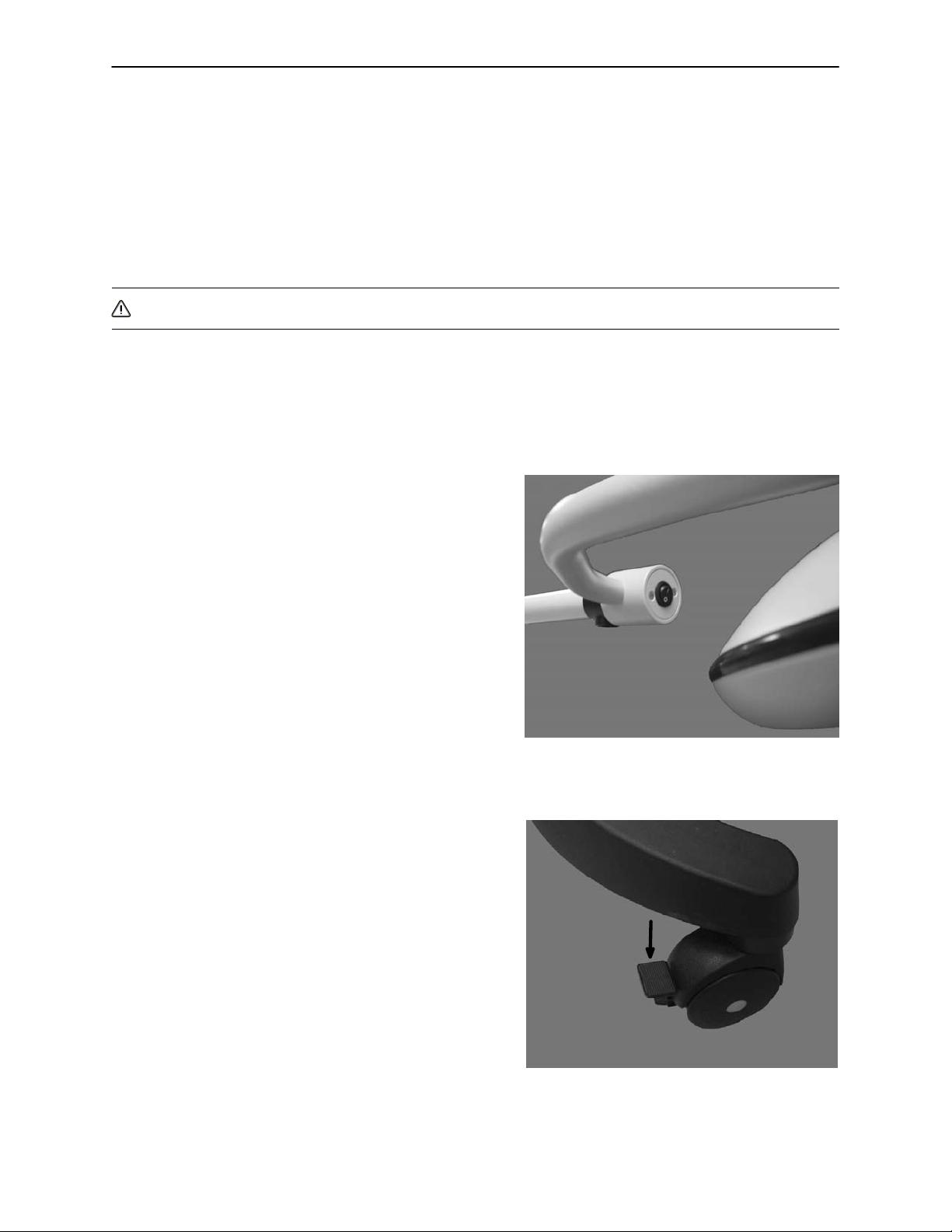
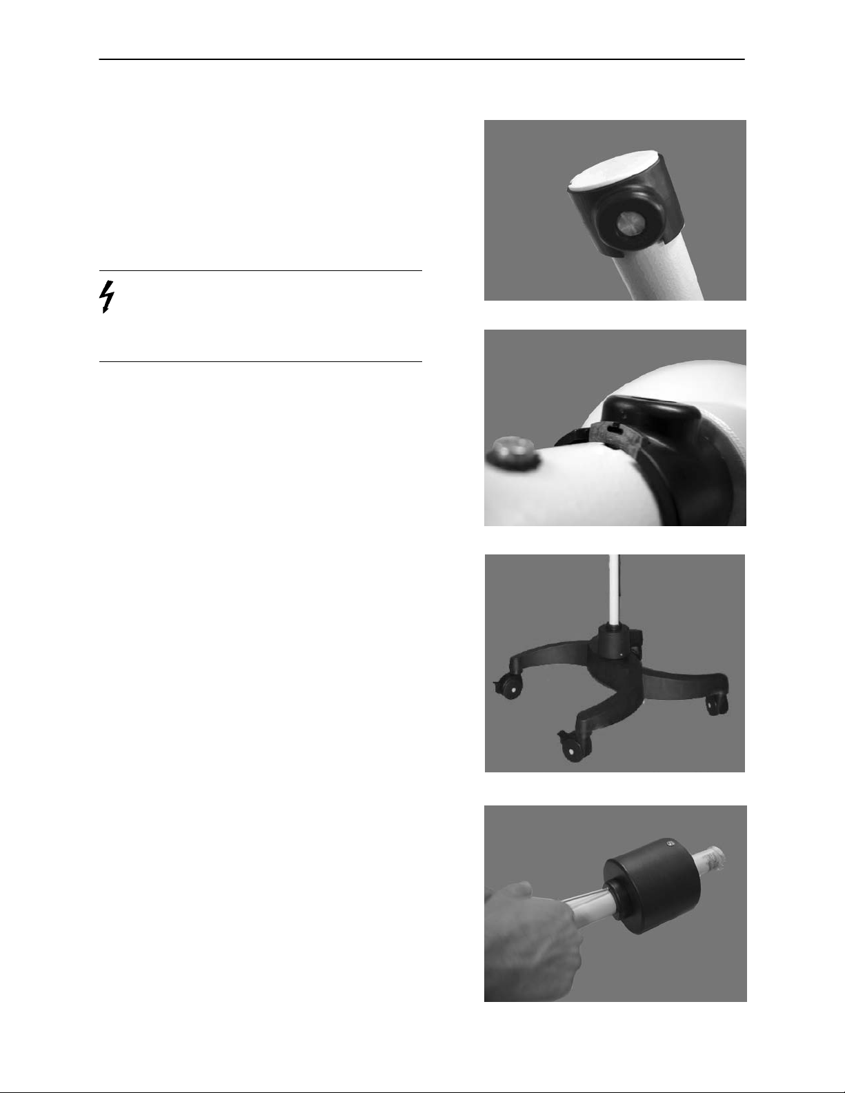
1. Using a regular screwdriver, remove the brake
screw at the end of the spring arm as shown in
Figure 6 and set aside for later use. Remove the
white plastic cap from the spring arm. Rotate the
locking cover 180 degrees in either direction so
that the keeper slot is exposed.
2. Align the end of the light head to the end of the
spring arm and push together until fully seated.
(Figure 7)
Figure 6.
3. Place the keeper clip from the accessory bag into
the fitted slot and push down until the clip is flushed
with the arm. (Figure 8)
4. Rotate the locking cover 180 degress in either di-
rection until the brake opening is faced down.
(Figure 9)
Figure 7.
Figure 8.
Figure 9.
5. Using a regular screwdriver, insert the brake
screw into the brake opening and check to make
sure assembly of light head is secure. (Figure 10)
10
Figure 10.
Page 12

Assembling the Light
Attaching the Light Handle Assembly
1. Position the system as shown in Figure 11.
2. Lock the system into position by pressing down
the tab on the end of each roller. (Figure 12)
Figure 11.
3. Connect the light bulb into the socket of the light
handle assembly. (Figure 13)
4. With one hand on the light handle assembly and
one hand on the back of the light head, carefully
insert the light handle assembly into the light head.
Align the banana clips to the power receptacles
and the screws to the threaded holes as shown in
figure 14. Screw the two thumbscrews until fully
seated.
Figure 12.
Figure 13.
11
Figure 14.
Page 13

Operations Guide
Adjusting the Light Head
The light can be used with or without a sterilizable handle.
Position the light in the following manner.
1. 360 degrees of rotation. (Figure 15)
Figure 15.
2. 180 degrees of rotation. (Figure 16)
3. 90 degrees of rotation. (Figure 17)
Figure 16.
Figure 17.
4. 60 degrees of rotation (Figure 18)
Figure 18.
12
Page 14
Operations Guide
Moving the Light
Before moving the light, put the light head down to its lowest position. Make sure the casters are released
from locked position.
NOTE
It is important to move the light only by the handle on the stand.
CAUTION − Instruction
Do not push, or pull the stand in any other areas other than the handle on the stand, otherwise tipping of the
stand may occur.
Turning On and Off
1. Light is shown in the Off position. (Figure 19)
Locking the Exam Light
1. To lock the exam light into position, simply press
down the tab on the end of each caster.
(Figure 20)
Figure 19.
13
Figure 20.
Page 15

Preventative Maintenance
WARNING
Maintenance must be performed by qualified service personnel. Always verify the power cord is unplugged
from the wall outlet before performing service.
The Stryker LL305 Visum Examination Light is equipped with a hospital grade plug for protection against
shock hazard. It must be plugged directly into a properly grounded three−prong receptacle. Grounding reliability can be achieved only when a hospital grade receptacle is used.
The light is hot while in operation. Do not touch the protective glass, reflector, or bulb while the light is turned
on or immediately after turning it off.
When replacing the halogen light bulb, use only the bulb specified in this manual. Allow the light to cool before
attempting maintenance. Do not touch the glass surface of the either the old or the new bulb. Use a soft cloth
to remove the old bulb and install the new one
Use only manufacturer approved replacement parts.
Preventative Maintenance Checklist
Preventative maintenance should be performed at a minimum of annually.
All fasteners secure on the lamp head and column
All casters secure and swivelling properly
Casters lock properly
Power cord not frayed
On/Off switch functions properly
Ground impedance not more than 100 milliohms
Current leakage not more than 300 microamps
Verify the spring force of arm and light head are proper.
Lubricate keeper clip.
14
Page 16

Preventative Maintenance
Cleaning And Disinfecting
NOTE − Qualifications of the personnel:
Cleaning and disinfecting must only be carried out by trained personnel.
WARNING − Electrical Shock
For all cleaning work, power off equipment, disconnect power cord from outlet. Take care that no fluid runs
into the equipment.
CAUTION − Damage to the product:
To avoid damage to plastic parts, do not use scouring agents, alkali, acidic or alcohol−containing cleaning
agents. Do not use disinfectant alcohol.
Cleaning
S Turn the light off
S Disconnect from power outlet
S Wipe the surfaces with a lightly moistened piece of cloth, if required, add a mild solution of soap (washing
agent).
Disinfecting
S Disinfect the equipment only when it is cool.
Sterile Handle
NOTE
The handle can easily be removed for cleaning or sterilization.
CAUTION − Handles are shipped non−sterile. Please clean and sterilize the handles prior to use.
Cleaning
S Rinse handle under running lukewarm water, flushing water through all passages.
S Submerge entire handle in an enzyme action detergent prepared according to the manufacturer’s recom-
mendations. Remove debris and bioburden from all surfaces using a soft brush.
S Rinse handle thoroughly under running lukewarm water, flushing water through all passages.
S Dry handle with a lint free cloth. Inspect handle to make sure it is free of debris.
Sterilization
The following sterilization methods have been validated:
S Gravity Displacement Steam sterilization(single wrapped)
Temperature: 132 degrees C (270 degrees F)
Exposure Time: 10 minutes
S Gravity Displacement Steam sterilization (double wrapped)
Temperature: 121 degrees C (250 degrees F)
Exposure Time: 25 minutes
S Pre−Vacuum Cycle (double wrapped)
Temperature: 134 degrees C (273 degrees F)
Exposure Time: 4 minutes
15
Page 17

Light is not working
Yes
Troubleshooting Guide
Check the bulb
for continuity.
Yes
Is there
115V at the brown
and blue wires coming
into the terminal block
in the handle
assembly?
Yes
No
No
Replace Bulb.
ref. pg. 23−24
Replace Power Cord.
ref. pg. 26−28
Yes
Yes
Test the Light for
functionality.
Yes
Return Light
to Service.
Check
continuity of the
1A fuses at the
terminal block in
the handle assembly.
ref. pg. 26−27
Yes
No
A
Replace Fuse.
ref. pg. 28
16
Yes
Page 18

A
If problem still exists, please contact Stryker Technical Support
Check for
115V at the violet
and black wires coming
into the transformer.
ref. pg. 29−30
Yes
Troubleshooting
at 1−800−327−0770 (option 2).
No
Replace the
Stand Assembly.
Yes
Check for
14 VAC on the red
wires coming out of
the transformer.
Yes
Check for
14 VAC at the
commutator.
Yes
No
No
Replace the
Transformer.
Replace the
Stand Assembly.
Yes
Test the Light for
functionality.
Yes
Yes
Return Light
to Service.
Check Light
Handle Assembly.
No
Replace the Light
Handle Assembly.
17
Yes
Page 19

Service Information
Setting the Spring Force
Tools Required
Regular Screwdriver
CAUTION − Instruction
Make sure to lock the casters before adjusting the spring tension.
NOTE
Adjust the spring force such that the spring arm with
the light head assembly does not drift when placed in
any desired position.
1. Pull off the elbow cap as shown in Figure 21.
2. Using a regular screwdriver, turn the knob shown
until the desired tension is reached. (Figure 22)
NOTE
If the spring arm drops, the spring force is too low
and the screw must be rotated counter−clockwise.
If the spring arm rised, the spring fcrce is too high
and the screw must be rotated clockwise.
Attaching/Removing the Sterilizable Light Handle Cover
1. To remove the optional sterilizable handle, press
the metal button and pull down on the handle. To
attach the handle, align the locking tab feature on
the light handle assembly and the optional sterilizable handle. Slide the handle onto the light handle
assembly and twist until the button secures the
sterilizable handle into place. A locking click will
be heard when secured. (Figure 23)
Figure 21.
Figure 22.
18
Figure 23
Page 20

Service Information
Changing the Halogen Light
WARNING − High Temperature
Allow the light to cool before attempting maintenance. The light is hot while in operation. Do not touch the
protective glass or bulb while the light is turned on or immediately after turning it off.
CAUTION − Instruction
If the optional sterile handle is on the light handle assembly, remove the sterile handle first (refer to section
Attaching/Removing the Sterilizable Light Handle Cover).
Only use the bulb specified in the Spare Parts section. The use of a bulb other than the one specified may
result in poor color reproduction or higher operating temperatures.
1. Turn off the light and disconnect from the power
outlet. Set the braking mechanism on the casters.
For easy access, place the light head in the position as shown in Figure 24.
2. Unscrew the two thumbscrews simultaneously
until the screws spin freely without resisitance.
Carefully pull the light handle assembly straight
out. (Figure 25)
Figure 24.
Figure 25.
3. Firmly grasp the bulb and pull straight out to re-
move it. Connect the replacment bulb into the
socket of the light handle assembly. (Figure 26)
Figure 26.
19
Page 21

Service Information
Changing the Halogen Light (continued)
1. With one hand on the light handle assembly and
one hand on the back of the light head, carefully
insert the light handle assembly into the light head.
Align the banana clips to the power receptacles
and the screws to the threaded holes as shown in
Figure 27. Screw the two thumbscrews until fully
seated.
Figure 27.
Replacing the Aesthetics Kit
Tools Required
Regular Screwdriver
Regular Screwdriver (small tip for removing Keeper Clip)
Phillips Head Screwdriver
Snap Ring Pliers (supplied)
1. Turn off the light and disconnect from the power
outlet. Remove the brake screw at the end of the
spring arm as shown in Figure 28. Set aside for
later use.
2. Rotate the brake cover 180 degrees and remove
the keeper clip. Remove the light head and set
aside for later use. Remove brake cover from the
end of the spring arm. (Figure 29)
Figure 28.
NOTE: If replacing brake cover only, then install
new brake cover and do not proceed to following
steps.
Figure 29.
20
Page 22

Service Information
Replacing the Aesthetics Kit (continued)
3. Remove the top end cap by removing the small
screw. If replacing top end cap only, install new
end cap and do not proceed to following steps.
(Figure 30)
Figure 30.
4. Remove elbow caps. (Figure 31)
5. Pull the cables out from the spring arm and
disconnect the cables. (Figure 32)
Figure 31.
Figure 32.
6. Using the supplied snap ring pliers, remove the
snap ring from the spriong arm. Remove the flat
washer and pull the spring arm from the stand.
(Figure 33)
Figure 33.
21
Page 23

Service Information
Replacing the Aesthetics Kit (continued)
7. Remove the elbow collars by sliding them off of the
spring arm. Slide new collars into place. Reassemble the spring arm following steps in reverse order. Place new elbow caps on if required.
(Figure 34)
8. Slide the elbow cover completely off by removing
the grounding screws shown in Figure 35 and the
brake cover from the end of the spring arm.
Figure 34.
Replacing the Electrical Kit
Tools Required
Regular Screwdriver (small tip)
Phillips Head Screwdriver
Torx Screwdriver
WARNING − Electrical Shock
Disconnect from power outlet to prevent electriclal
shock.
1. Turn off the light and disconnect it from the power
outlet. Using a Torx Screwdriver, remove the two
screws from the handle as shown in Figure 36.
2. Pull handle apart as shown in Figure 37.
Figure 35.
Figure 36.
22
Figure 37.
Page 24

Service Information
Replacing the Electrical Kit (continued)
3. Remove the screws to release cord. (Figure 38)
4. Loosen the three screws from the fuse holder to
release the cord entirely from the handle.
(Figure 39)
Figure 38.
5. The Electrical Kit comes with an extra connector
and fuse holder. If replacing the handle and/or
fuse holder, remove the screw holding the fuse
holder in. Loosen the screws holding the wires to
the fuse holder if replacing with a new fuse holder.
(Figure 40)
6. Insert the line wire (brown) through the fuse holder
and the neutral wire (blue) through the other connection. Insert the ground wire (green/yellow)
through the connector. (Figure 41)
Figure 39.
Figure 40.
23
Figure 41.
Page 25

Service Information
Replacing the Electrical Kit (continued)
7. Attach the fuse holder to the stand. Insert two
1−amp fuses into the fuse holder as shown in
Figure 42.
8. Secure power cord with the strain relief and two
screws. (Figure 43)
Figure 42.
9. Place the new handle on and ensure the two extru-
sions fit into the two openings of the stand. The
cord should be coming down. Snap back into
place and screw handle together. (Figure 44)
Figure 43.
Figure 44.
24
Page 26
Service Information
Replacing the Transformer
Tools Required
Regular Screwdriver (small tip)
Phillips Head Screwdriver
Phillips Head Screwdriver (small tip)
2mm Allen wrench
WARNING − Electrical Shock
Disconnect from power outlet to prevent electriclal
shock.
1. Turn off the light and disconnect it from the power
outlet. Remove the brake screw at the end of the
spring arm as shown in Figure 45. Set the brake
screw aside for later use.
2. Rotate the brake cover 180 degrees and remove
the keeper clip. Remove the light head.
(Figure 46)
Figure 45.
Figure 46.
3. Remove the wing screw from the bottom of the
stand. Pull off the stand from the base. (Figure 47)
4. Place the stand on a flat surface on a piece of card-
board or cloth to prevent surface damage. Remove the two small screws from the collars as
shown in Figure 48. Detach the collars.
Figure 47.
Figure 48.
25
Page 27

Service Information
Replacing the Transformer (continued)
5. Remove the two side screws on the transformer
cover. Once removed, push the cover up towards
the spring arm to expose the transformer.
(Figure 49)
6. Unscrew the grounding cable from the stand.
(Figure 50)
Figure 49.
7. Loosen the three screws on the top plate of the
transformer with an Allen wrench. Ensure the
screws are not exposed on either end. There
should be enough space in the top plate for the
screw to remain inside the plate. (Figure 51)
8. Disconnect the wires from the connector as shown
in Figure 52. Refer to wiring diagram below.
Connection for 115V
RedBlack
115 VAC
Primary
Orange
14 VAC
Secondary
Figure 50.
Figure 51.
White
Violet
Red
Figure 52.
26
Page 28
Service Information
Replacing the Transformer (continued)
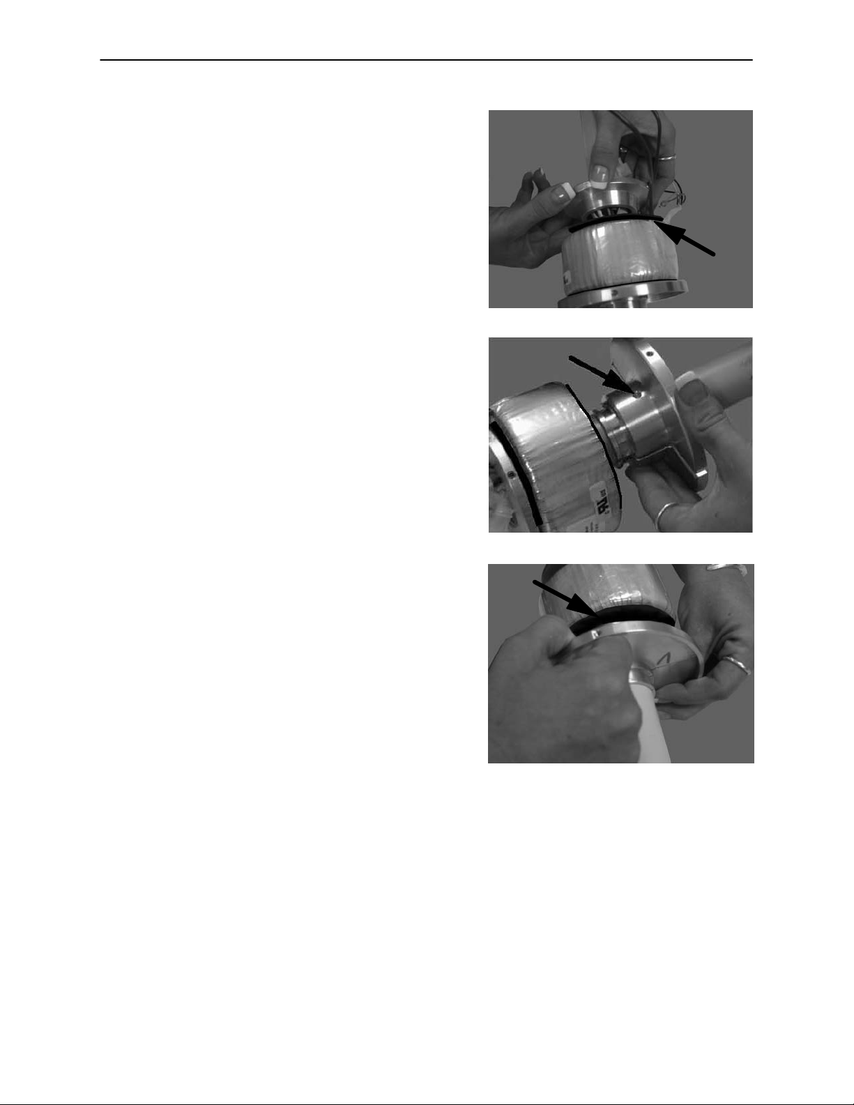
9. Carefully slide the top plate and the top rubber
grommet up around the wires. Slide the transformer and the bottom rubber grommet up afterwards. (Figure 53)
10. Using a Phillips screwdriver, remove the screw
that holds the bottom plates together. (Figure 54)
Figure 53.
Figure 54.
1 1. Pull apart the bottom plates from the stand. Slide
the transformer and the bottom grommet off of the
stand. If installing a new transformer cover, slide
the top plate, top grommet, and existing cover off.
Slide the new cover on, followed by the top plate
and the top grommet. If installing a new transformer, slide new transformer on. Place bottom grommet on, re−attach bottom plates, and put back
together using steps above in reverse order.
(Figure 55)
Figure 55.
Greasing the Keeper Clip
1. Dismantle the light head.
2. Check the keeper clip for a minimum thickness of 1.5 mm and if required, replace it.
3. Grease the keeper clip and the pin of the light head.
4. Assemble the light head.
27
Page 29

Replacement Parts
Replacement Parts
For the following or any other replacement parts, please contact Stryker Customer Service at
1−800−327−0770 (Option 1).
Dispose of all removed light bulbs and parts in accordance with local regulations.
8500−000−010 Light Handle Assembly. . . . . . . . . . . . . . . .
8500−000−009 Sterile Handle. . . . . . . . . . . . . . . .
8500−000−008 Light Bulb. . . . . . . . . . . . . . . .
8500−000−011 Hardware Kit. . . . . . . . . . . . . . . .
Qty = 3
Qty = 5
Brake Screw
Wing Screw
28
Keeper Clip
Page 30

Replacement Parts
Replacement Parts (continued)
8500−000−007 Anti−Static Casters. . . . . . . . . . . . . . . .
Qty = 4
8500−000−012 Aesthetics Kit. . . . . . . . . . . . . . . .
8500−000−013 Electrical Kit. . . . . . . . . . . . . . . .
Elbow Caps
Top End Cap
Handle
for Stand
Brake Cover
Medical
Grade Cord
Fuse Holder
Fuse
Qty = 2
29
Page 31

Replacement Parts
Replacement Parts (continued)
8500−000−006 Transformer Cover. . . . . . . . . . . . . . . .
8500−000−005 Transformer, 115V. . . . . . . . . . . . . . . .
8500−000−004 Fuse, 1 Amp. . . . . . . . . . . . . . . .
8500−000−060 Spring Arm. . . . . . . . . . . . . . . .
Qty = 5 Pack
with Brake Cover
30
Page 32

Replacement Parts
Replacement Parts (continued)
8500−000−030 Base Assembly. . . . . . . . . . . . . . . .
1 Base
8500−000−050 Light Head Assembly. . . . . . . . . . . . . . . .
4 Anti−Static casters with brakes
1 Light Handle Assembly
1 Light Bulb
1 Light Head
31
Page 33

Replacement Parts
Replacement Parts (continued)
1 Spring Arm with Brake Cover
1 Stand with handle, top end cap,
transformer, and transformer cover.
8500−000−040 Spring Arm Assembly. . . . . . . . . . . . . . . .
1 Keeper Clip
1Wing Screw
1 Flat Washer
1 Snap Ring Pliers
1 Brake Screw
1 Snap Ring
32
Page 34

Troubleshooting
Warranty
Stryker warrants that its Examination Lights are warranted against defective materials and workmanship for
two years from the date of purchase. Warranty applies to normal usage and does not apply to any product
that has been subject to alteration, abuse, negligence or use (including voltage and/or current) other than that
for which the product was designed. This warranty is limited to replacement, repair or refund at Stryker’s
option. Lamps (bulbs) are not covered by this warranty.
33
Page 35

3800 E. Centre Ave, Portage, MI 49002
(800) 327−0770
www.stryker.com
JH 4/06 8500−009−001 REV D
 Loading...