

Page 1
IMPORTANT
File in your
maintenance
records
Transport Stretcher
Model 721
MAINTENANCE MANUAL
For Parts or Technical Assistance
1−800−327−0770 (Option 2)
Page 2

Table of Contents
Introduction
Specifications 4. . . . . . . . . . . . . . . . . . . . . . . . . . . . . . . . . . . . . . . . . . . . . . . . . . . . . . . . . . . . . . . . . . . . . . . . . . . .
Warning / Caution / Note Definition 4. . . . . . . . . . . . . . . . . . . . . . . . . . . . . . . . . . . . . . . . . . . . . . . . . . . . . . . . .
Preventative Maintenance
Checklist 5. . . . . . . . . . . . . . . . . . . . . . . . . . . . . . . . . . . . . . . . . . . . . . . . . . . . . . . . . . . . . . . . . . . . . . . . . . . . . . . .
Cleaning 6. . . . . . . . . . . . . . . . . . . . . . . . . . . . . . . . . . . . . . . . . . . . . . . . . . . . . . . . . . . . . . . . . . . . . . . . . . . . . . . .
Service Information
Caster Cover Installation and Removal 7. . . . . . . . . . . . . . . . . . . . . . . . . . . . . . . . . . . . . . . . . . . . . . . . . . . . . .
Caster Removal 7. . . . . . . . . . . . . . . . . . . . . . . . . . . . . . . . . . . . . . . . . . . . . . . . . . . . . . . . . . . . . . . . . . . . . . . . . .
Brake Rod Removal 8. . . . . . . . . . . . . . . . . . . . . . . . . . . . . . . . . . . . . . . . . . . . . . . . . . . . . . . . . . . . . . . . . . . . . .
Side Control Brake Rod Removal 9. . . . . . . . . . . . . . . . . . . . . . . . . . . . . . . . . . . . . . . . . . . . . . . . . . . . . . . . . . .
Release Pedal Adjustment 9. . . . . . . . . . . . . . . . . . . . . . . . . . . . . . . . . . . . . . . . . . . . . . . . . . . . . . . . . . . . . . . .
Foot End Release Pedal Replacement 10. . . . . . . . . . . . . . . . . . . . . . . . . . . . . . . . . . . . . . . . . . . . . . . . . . . . .
Foot End Release Pedal Rod Removal 10. . . . . . . . . . . . . . . . . . . . . . . . . . . . . . . . . . . . . . . . . . . . . . . . . . . . .
Brake Ring Removal 11. . . . . . . . . . . . . . . . . . . . . . . . . . . . . . . . . . . . . . . . . . . . . . . . . . . . . . . . . . . . . . . . . . . . .
Fifth Wheel Assembly Removal 11. . . . . . . . . . . . . . . . . . . . . . . . . . . . . . . . . . . . . . . . . . . . . . . . . . . . . . . . . . .
Big Wheel Hubcap Removal 12. . . . . . . . . . . . . . . . . . . . . . . . . . . . . . . . . . . . . . . . . . . . . . . . . . . . . . . . . . . . . .
Litter Top Removal 12. . . . . . . . . . . . . . . . . . . . . . . . . . . . . . . . . . . . . . . . . . . . . . . . . . . . . . . . . . . . . . . . . . . . . .
Big Wheel Carriage Removal 13. . . . . . . . . . . . . . . . . . . . . . . . . . . . . . . . . . . . . . . . . . . . . . . . . . . . . . . . . . . . .
Big Wheel Removal 13. . . . . . . . . . . . . . . . . . . . . . . . . . . . . . . . . . . . . . . . . . . . . . . . . . . . . . . . . . . . . . . . . . . . .
Big Wheel Cam Gas Spring Dampener Removal 14. . . . . . . . . . . . . . . . . . . . . . . . . . . . . . . . . . . . . . . . . . . .
Side Control Big Wheel Linkage Assembly Removal 14. . . . . . . . . . . . . . . . . . . . . . . . . . . . . . . . . . . . . . . . .
Jack Descent Rate Adjustment 15. . . . . . . . . . . . . . . . . . . . . . . . . . . . . . . . . . . . . . . . . . . . . . . . . . . . . . . . . . . .
Removal of Excess Air from the Hydraulic System 15. . . . . . . . . . . . . . . . . . . . . . . . . . . . . . . . . . . . . . . . . . .
Head End Hydraulic Jack Removal 16. . . . . . . . . . . . . . . . . . . . . . . . . . . . . . . . . . . . . . . . . . . . . . . . . . . . . . . .
Foot End Hydraulic Jack Removal 16, 17. . . . . . . . . . . . . . . . . . . . . . . . . . . . . . . . . . . . . . . . . . . . . . . . . . . . . .
Pneumatic Fowler Adjustment 17. . . . . . . . . . . . . . . . . . . . . . . . . . . . . . . . . . . . . . . . . . . . . . . . . . . . . . . . . . . .
Transfer Board Counterbalance Adjustment 18. . . . . . . . . . . . . . . . . . . . . . . . . . . . . . . . . . . . . . . . . . . . . . . . .
Folddown Siderail LatchAdjustment 18. . . . . . . . . . . . . . . . . . . . . . . . . . . . . . . . . . . . . . . . . . . . . . . . . . . . . . . .
Quick Reference Replacement Parts List 19, 20. . . . . . . . . . . . . . . . . . . . . . . . . . . . . . . . . . . . . . . . . . . . . . . . . .
Page 3

Table of Contents
Assembly Drawings and Parts Lists
Fifth Wheel Base Assembly 21. . . . . . . . . . . . . . . . . . . . . . . . . . . . . . . . . . . . . . . . . . . . . . . . . . . . . . . . . . . . . .
Fifth Wheel Assembly 22, 23. . . . . . . . . . . . . . . . . . . . . . . . . . . . . . . . . . . . . . . . . . . . . . . . . . . . . . . . . . . . . . . . .
Base Assembly with Standard Brakes (Fifth Wheel Base) 24, 25. . . . . . . . . . . . . . . . . . . . . . . . . . . . . . . . . .
Brake Rod Assembly 26. . . . . . . . . . . . . . . . . . . . . . . . . . . . . . . . . . . . . . . . . . . . . . . . . . . . . . . . . . . . . . . . . . . .
Drive Link Assembly 27, 28. . . . . . . . . . . . . . . . . . . . . . . . . . . . . . . . . . . . . . . . . . . . . . . . . . . . . . . . . . . . . . . . . .
Caster Assembly 29. . . . . . . . . . . . . . . . . . . . . . . . . . . . . . . . . . . . . . . . . . . . . . . . . . . . . . . . . . . . . . . . . . . . . . . .
Base Assembly with Four−Sided Brakes 30, 31. . . . . . . . . . . . . . . . . . . . . . . . . . . . . . . . . . . . . . . . . . . . . . . .
Side Control Brake Rod Assembly 32. . . . . . . . . . . . . . . . . . . . . . . . . . . . . . . . . . . . . . . . . . . . . . . . . . . . . . . . .
Brake Rod Assembly 33. . . . . . . . . . . . . . . . . . . . . . . . . . . . . . . . . . . . . . . . . . . . . . . . . . . . . . . . . . . . . . . . . . . .
Base Assembly with Dual Side Hydraulics (Fifth Wheel Base) 34−36. . . . . . . . . . . . . . . . . . . . . . . . . . . . . .
Release Pedal Assembly 37. . . . . . . . . . . . . . . . . . . . . . . . . . . . . . . . . . . . . . . . . . . . . . . . . . . . . . . . . . . . . . . . .
Pump Pedal Assembly 38. . . . . . . . . . . . . . . . . . . . . . . . . . . . . . . . . . . . . . . . . . . . . . . . . . . . . . . . . . . . . . . . . . .
Base Labeling Assembly 39−41. . . . . . . . . . . . . . . . . . . . . . . . . . . . . . . . . . . . . . . . . . . . . . . . . . . . . . . . . . . . . .
Big Wheel Base Assembly 43−45. . . . . . . . . . . . . . . . . . . . . . . . . . . . . . . . . . . . . . . . . . . . . . . . . . . . . . . . . . . . .
Base Assembly with Standard Brakes (Big Wheel Base) 46, 47. . . . . . . . . . . . . . . . . . . . . . . . . . . . . . . . . . .
Drive Link Assembly 48. . . . . . . . . . . . . . . . . . . . . . . . . . . . . . . . . . . . . . . . . . . . . . . . . . . . . . . . . . . . . . . . . . . . .
Brake Rod Assembly 49. . . . . . . . . . . . . . . . . . . . . . . . . . . . . . . . . . . . . . . . . . . . . . . . . . . . . . . . . . . . . . . . . . . .
Base Assembly with Dual Side Hydraulics (Big Wheel Base) 50−52. . . . . . . . . . . . . . . . . . . . . . . . . . . . . . .
Cam Bracket Assembly 54, 55. . . . . . . . . . . . . . . . . . . . . . . . . . . . . . . . . . . . . . . . . . . . . . . . . . . . . . . . . . . . . . .
Big Wheel Carriage Assembly 56. . . . . . . . . . . . . . . . . . . . . . . . . . . . . . . . . . . . . . . . . . . . . . . . . . . . . . . . . . . .
Side Control Big Wheel Base Assembly 57−59. . . . . . . . . . . . . . . . . . . . . . . . . . . . . . . . . . . . . . . . . . . . . . . . .
Side Control Big Wheel Carriage Assembly 60, 61. . . . . . . . . . . . . . . . . . . . . . . . . . . . . . . . . . . . . . . . . . . . . .
Side Control Big Wheel Linkage Assembly 62. . . . . . . . . . . . . . . . . . . . . . . . . . . . . . . . . . . . . . . . . . . . . . . . . .
Base Labeling Assembly 63, 64. . . . . . . . . . . . . . . . . . . . . . . . . . . . . . . . . . . . . . . . . . . . . . . . . . . . . . . . . . . . . .
Variable Descent Hydraulic Jack Option 65. . . . . . . . . . . . . . . . . . . . . . . . . . . . . . . . . . . . . . . . . . . . . . . . . . . .
Constant Descent Hydraulic Jack Option 66. . . . . . . . . . . . . . . . . . . . . . . . . . . . . . . . . . . . . . . . . . . . . . . . . . .
Litter Assembly 67−69. . . . . . . . . . . . . . . . . . . . . . . . . . . . . . . . . . . . . . . . . . . . . . . . . . . . . . . . . . . . . . . . . . . . . .
Siderail Assembly 70. . . . . . . . . . . . . . . . . . . . . . . . . . . . . . . . . . . . . . . . . . . . . . . . . . . . . . . . . . . . . . . . . . . . . . .
Manual Fowler Assembly 71. . . . . . . . . . . . . . . . . . . . . . . . . . . . . . . . . . . . . . . . . . . . . . . . . . . . . . . . . . . . . . . . .
Pneumatic Fowler Assembly 72−74. . . . . . . . . . . . . . . . . . . . . . . . . . . . . . . . . . . . . . . . . . . . . . . . . . . . . . . . . . .
Transfer System Assembly 75−80. . . . . . . . . . . . . . . . . . . . . . . . . . . . . . . . . . . . . . . . . . . . . . . . . . . . . . . . . . . .
Page 4

Table of Contents
Assembly Drawings and Parts Lists (Continued)
Removable I.V. Pole Assembly 81. . . . . . . . . . . . . . . . . . . . . . . . . . . . . . . . . . . . . . . . . . . . . . . . . . . . . . . . . . . .
Tethered I.V. Pole Assembly 82, 83. . . . . . . . . . . . . . . . . . . . . . . . . . . . . . . . . . . . . . . . . . . . . . . . . . . . . . . . . . .
2−Stage I.V. Assembly 84−86. . . . . . . . . . . . . . . . . . . . . . . . . . . . . . . . . . . . . . . . . . . . . . . . . . . . . . . . . . . . . . . .
3−Stage I.V. Assembly 87−89. . . . . . . . . . . . . . . . . . . . . . . . . . . . . . . . . . . . . . . . . . . . . . . . . . . . . . . . . . . . . . . .
C−Spine Cassette Holder Assembly 90−92. . . . . . . . . . . . . . . . . . . . . . . . . . . . . . . . . . . . . . . . . . . . . . . . . . . .
Defibrillator Tray Assembly 93. . . . . . . . . . . . . . . . . . . . . . . . . . . . . . . . . . . . . . . . . . . . . . . . . . . . . . . . . . . . . . .
Foot Extension/Defibrillator Tray Assembly 94. . . . . . . . . . . . . . . . . . . . . . . . . . . . . . . . . . . . . . . . . . . . . . . . .
Foot Board 95. . . . . . . . . . . . . . . . . . . . . . . . . . . . . . . . . . . . . . . . . . . . . . . . . . . . . . . . . . . . . . . . . . . . . . . . . . . . .
O2 Bottle Holder 95,96. . . . . . . . . . . . . . . . . . . . . . . . . . . . . . . . . . . . . . . . . . . . . . . . . . . . . . . . . . . . . . . . . . . . .
Mattresses and Siderail Pads 97, 98. . . . . . . . . . . . . . . . . . . . . . . . . . . . . . . . . . . . . . . . . . . . . . . . . . . . . . . . . .
Warranty
Obtaining Parts and Service 99. . . . . . . . . . . . . . . . . . . . . . . . . . . . . . . . . . . . . . . . . . . . . . . . . . . . . . . . . . . . . .
Service Contract Coverage 99. . . . . . . . . . . . . . . . . . . . . . . . . . . . . . . . . . . . . . . . . . . . . . . . . . . . . . . . . . . . . . .
Return Authorization 100. . . . . . . . . . . . . . . . . . . . . . . . . . . . . . . . . . . . . . . . . . . . . . . . . . . . . . . . . . . . . . . . . . . .
Freight Damage Claims 100. . . . . . . . . . . . . . . . . . . . . . . . . . . . . . . . . . . . . . . . . . . . . . . . . . . . . . . . . . . . . . . . .
Page 5

Introduction
INTRODUCTION
This manual is designed to assist you with the maintenance of the Model 721 Advanced Transport Stretcher.
Read it thoroughly before using the equipment or beginning any maintenance on it.
SPECIFICATIONS
Maximum Weight Capacity 500 pounds
Overall Stretcher Length \ Width 83” / 30”
Minimum \ Maximum Bed Height 21.5” / 36”
Fowler Angle 0_ to 90_
Trendelenburg \ Reverse Trendelenburg +18_ to −18_
Stryker reserves the right to change specifications without notice.
WARNING / CAUTION / NOTE DEFINITION
The words WARNING, CAUTION and NOTE carry special meanings and should be carefully reviewed.
WARNING
Alerts the reader about a situation, which if not avoided, could result in death or serious injury. It may also
describe potential serious adverse reactions and safety hazards.
CAUTION
Alerts the reader of a potentially hazardous situation, which if not avoided, may result in minor or moderate
injury to the user or patient or damage to the equipment or other property. This includes special care necessary for the safe and effective use of the device and the care necessary to avoid damage to a device that
may occur as a result of use or misuse.
NOTE
This provides special information to make maintenance easier or important instructions clearer.
4
Page 6

Preventative Maintenance
CHECKLIST
All fasteners secure
Siderails move and latch properly
Engage the brake pedal and push on the stretcher to ensure all casters lock securely
All casters secure and swiveling properly
Body restraints working properly
I.V. pole intact and operating properly
Oxygen bottle holder intact and operating properly
Fowler operates and latches properly
Trendelenburg/Reverse Trendelenburg operating properly
No rips or cracks in mattress cover
Transfer boards intact and operating properly
Ground chain intact
No leaks at hydraulic connections
Hydraulic jacks holding properly
Hydraulic drop rate set properly
Hydraulic oil level sufficient
Lubricate where required
Accessories and mounting hardware in good condition and working properly
Serial No. ______________
______________
______________
______________
______________
Completed By:_________________________________ Date:_____________
NOTE
Preventative maintenance should be performed at a minimum of annually. A preventative maintenance program should be established for all Stryker Medical equipment. Preventative maintenance may need to be
performed more frequently based on the usage level of the product.
5
Page 7

Cleaning
Hand wash all surfaces of the stretcher with warm water and mild detergent. Dry thoroughly. DO NOT
STEAM CLEAN, PRESSURE WASH, HOSE OFF OR ULTRASONICALLY CLEAN. Using these methods
of cleaning is not recommended and may void this product’s warranty.
Clean Velcro AFTER EACH USE. Saturate Velcro with disinfectant and allow disinfectant to evaporate. (Appropriate disinfectant for nylon Velcro should be determined by the hospital.)
In general, when used in those concentrations recommended by the manufacturer, either phenolic type or
quaternary type disinfectants can be used. Iodophor type disinfectants are not recommended for use because staining may result. The following products have been tested and have been found not to have a harmful effect WHEN USED IN ACCORDANCE WITH MANUFACTURERS RECOMMENDED DILUTION.*
*MANUFACTURER’S
TRADE NAME DISINFECTANT
TYPE
A33 Quaternary Airwick (Professional Products Division) 2 ounces/gallon
A33 (dry) Quaternary Airwick (Professional Products Division) 1/2 ounce/gallon
Beaucoup Phenolic Huntington Laboratories 1 ounce/gallon
Blue Chip Quaternary S.C. Johnson 2 ounces/gallon
Elimstaph Quaternary Walter G. Legge 1 ounce/gallon
Franklin Phenomysan F2500 Phenolic Purex Corporation 1 1/4 ounce/gallon
Franklin Sentinel Quaternary Purex Corporation 2 ounces/gallon
Galahad Phenolic Puritan Churchill Chemical Company 1 ounce/gallon
Hi−Tor Quaternary Huntington Laboratories 1/2 ounce/gallon
LPH Phenolic Vestal Laboratories 1/2 ounce/gallon
Matar Phenolic Huntington Laboratories 1/2 ounce/gallon
Omega Quaternary Airwick (Professional Products Division) 1/2 ounce/gallon
Quanto Quaternary Huntington Laboratories 1 ounce/gallon
Sanikleen Quaternary West Chemical Products 2 ounces/ gallon
Sanimaster II Quaternary Service Master 1 ounce/gallon
Vesphene Phenolic Vestal Laboratories 1 1/4 ounce/ gallon
MANUFACTURER
RECOMMENDED
DILUTION
Quaternary Germicidal Disinfectants, used as directed, and/or Chlorine Bleach products, typically 5.25% So dium Hypochlorite in dilutions ranging between 1 part bleach to 100 parts water, and 2 parts bleach
to 100 parts water are not considered mild detergents. These products are corrosive in nature and
may cause damage to your stretcher if used improperly. If these types of products are used to clean
Stryker patient handling equipment, measures must be taken to insure the stretchers are rinsed with clean
water and thoroughly dried following cleaning. Failure to properly rinse and dry the stretchers will leave a corrosive residue on the surface of the stretcher, possibly causing premature corrosion of critical components.
NOTE
Failure to follow the above directions when using these types of cleaners may void this product’s warranty.
REMOVAL OF IODINE COMPOUNDS
This solution may be used to remove iodine stains from mattress cover surfaces.
1. Use a solution of 1−2 tablespoons Sodium Thiosulfate in a pint of warm water to clean the stained area.
Clean as soon as possible after staining occurs. If stains are not immediately removed, allow solution to
soak or stand on the surface.
2. Rinse surfaces which have been exposed to the solution in clear water before returning bed to service.
6
Page 8
Service Information
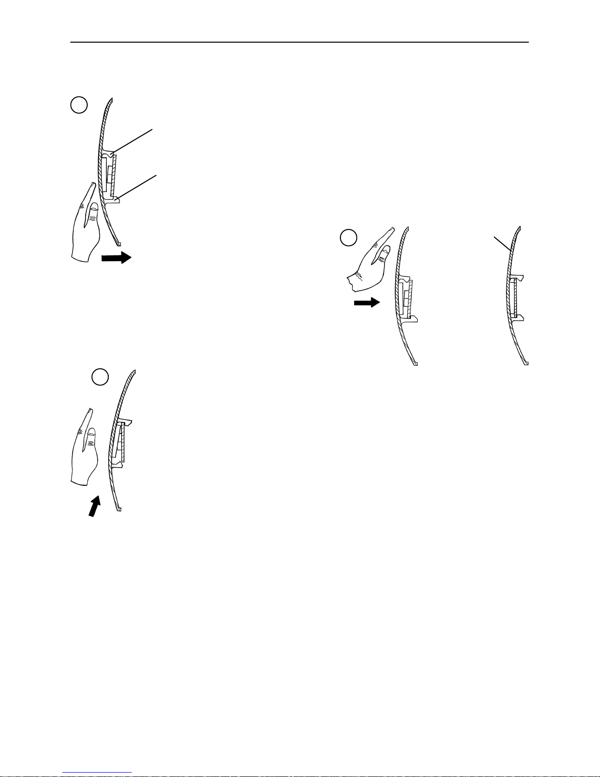
CASTER COVER INSTALLATION AND REMOVAL
1.
Double Prongs
Looking through the larger of the two side cut−outs,
align the cover with the axle nut or bolt head, as shown.
Single Prong
Push down on the opposite side of the cover until the
single prong engages the caster horn.
3.
Top View (Cut−Away)
Push on the cover with your palm until
the double prongs engage.
To remove the wheel cover, insert a large screwdriver into the cut−out
in the side of the wheel cover and into the space between the double
prongs. Pry up the cover to disengage the double prongs and push
sharply upward to disengage the single prong.
Top View (Cut−Away)
2.
Properly Attached
Cover
Top View (Cut−Away)
CASTER REMOVAL
Required Tools:
9/16” Open End Wrench
1. Remove the caster cover.
2. While keeping pressure on the caster bolt with your index finger, use a 9/16” open end wrench to remove
the nylock hex nut on top of the caster assembly.
3. Using the brake ring, lift up on the base assembly and pull the caster assembly down to remove it.
4. Reverse steps 1−3 to install the new caster.
7
Page 9

Service Information
BRAKE ROD REMOVAL
Required Tools:
Hammer 7/32” Punch String or Bungee Cords
Fifth Wheel Base
1. Pump the litter up to full height.
2. Lift the base hood and support it from the litter using string or bungee cords.
3. Remove the hex head cap screws connecting the brake rod supports to the base frame.
4. Remove the bolt connecting the drive link assembly to the fifth wheel cam.
5. Remove the rue ring cotter and clevis pin connecting the rod end link to the side control link.
6. Remove the rue ring cotter connecting the drive link assembly to the bearing pivot support on the base
frame (under the brake ring weldment).
7. Remove the three hex washer head screws holding the brake rod assembly to the base frame.
8. Remove the slotted spring pins connecting the butterfly “V” pedals, drive link assemblies and side control
link to the brake rod.
9. Reverse steps 1−8 to reinstall the brake rod. When reinstalling the brake rod supports, torque the hex
head cap screws to 12−15 ft.−lbs.
CAUTION
When reattaching the brake rod assembly to the base frame, set the torque specs no higher than 15 ft.−lbs.
or damage could occur to the bolts.
Big Wheel Base
1. Pump the litter up to full height.
2. Lift the base hood and support it from the litter using string or bungee cords.
3. With the brake/steer pedal in the steer position, remove the clevis pin and rue ring cotter connecting the
brake rod to the brake rod drive link at each end of the stretcher.
4. Remove the two clevis pins and rue ring cotters connecting the brake rods to the drive arm at the center
of the base near the cam bracket assembly.
5. Pull on the butterfly “V” pedals to remove the brake rods from the base.
6. Reverse steps 1−5 to reinstall the brake rod.
8
Page 10

Service Information
SIDE CONTROL BRAKE ROD REMOVAL
Required Tools:
Fifth Wheel Base
1. Pump the litter up to full height.
2. Lift the base hood and support it from the litter using string or bungee cords.
3. Remove the rue ring cotter and clevis pin connecting the rod end link to the side control link.
4. Remove the four bolts holding the brake rod assembly to the base frame and remove the entire assembly.
5. Using a hammer and 7/32” punch, drive the slotted spring pin out of the butterfly “V” pedal on the patient’s
left side and remove the pedal,
6. Using a hammer and 7/32” punch, drive the slotted spring pin out of the hard stop in the center of the
support weldment.
7. Using a hammer and 7/32” punch, drive out the slotted spring pin connecting the side control link to the
side control brake rod on the patient’s right side.
8. Pull on the butterfly “V” pedal on the patient’s right side to remove the side control brake rod from the base.
9. Reverse steps 1−8 to reinstall the brake rod. When reinstalling the assembly, torque the hex head cap
screws to 12−15 ft.−lbs.
CAUTION
When reattaching the brake rod assembly to the base frame, set the torque specs no higher than 15 ft.−lbs.
or damage could occur to the bolts.
Hammer 7/32” Punch Needle Nose Pliers String or Bungee Cords
Big Wheel Base
1. Pump the litter up to full height.
2. Lift the base hood and support it from the litter using string or bungee cords.
3. Using a hammer and 7/32” punch, drive the groove pin out of the butterfly “V” pedal on the patient’s left
side and remove the pedal.
4. Using a hammer and 7/32” punch, drive out the groove pin connecting the side control link to the side
control brake rod.
5. Pull on the butterfly “V” pedal on the patient’s right side to remove the side control brake rod from the base.
6. Reverse steps 1−5 to reinstall the brake rod.
RELEASE PEDAL ADJUSTMENT
1. Manually disengage the release pedal swivel (item J on page 35) from the release pedal assembly.
2. To increase the release rod engagement with the release valve, turn the release pedal swivel clockwise
on the threaded release rod.
3. To decrease the release rod engagement with the release valve, turn the release pedal swivel counter-
clockwise on the threaded release rod.
NOTE
If the pedal swivel assembly is threaded too far onto the release rod, the release valve will be partially activated and the jack will drift.
9
Page 11

Service Information
FOOT END RELEASE PEDAL REPLACEMENT
Required Tools:
1. Apply the stretcher brakes.
2. Disconnect the release pedal return springs from the foot end release pedals.
3. Remove the rue ring cotters and the clevis pins connecting the foot end release pedals to the mounting
bracket.
4. Rotate the pedals upward.
5. Remove the rue ring cotters connecting the head end and foot end release rods to the foot end release
pedals and remove the pedals.
6. Reverse steps 2−5 to install the new pedals.
Needle Nose Pliers
FOOT END RELEASE PEDAL ROD REMOVAL
Required Tools:
1. Remove the foot end release pedal (see procedure above).
2. Remove the snap in nyliners holding the foot end pedal release rods in the pedal mounting bracket.
3. Unsnap the foot end pedal release rods from the white plastic release rod brackets.
Needle Nose Pliers
4. Dislodge the side control release pedal swivels from the studs on the side control release pedal weldments.
5. Remove the foot end pedal release rods.
6. Reverse steps 1−5 to reinstall the pedal rods.
10
Page 12

Service Information
BRAKE RING REMOVAL
Required Tools:
9/16” Socket w/Extension 3/8” Drive Ratchet Needle−Nose Pliers String or Bungee Cord
1. Pump the litter up to full height.
2. Lift the base hood and support it from the litter using string or bungee cords.
3. Using needle−nose pliers, unhook the extension springs from the top of the base caster tubes.
4. Remove the plastic caster covers.
5. While putting pressure on the caster carriage bolt, use a 9/16” socket and a 3/8” drive ratchet to remove
the caster nut on both sides of the stretcher.
6. Remove the casters.
7. Remove the brake rod (see procedure).
8. Remove the cotter pin from the clevis pin in the center of the brake ring weldment.
9. Remove the cotter pin from the bearing pivot support.
10. Remove the 3/4” nylock hex nut from the bearing pivot support.
11. Remove the drive link assembly.
12. Pull the brake ring down and out away from the stretcher base frame.
13. Reverse steps 1−12 to reinstall the brake ring.
FIFTH WHEEL ASSEMBLY REMOVAL
Required Tools:
1/2” Socket 3/8” Drive Ratchet
1. Using a 1/2” socket and 3/8” drive ratchet, remove the 1/2” bolt holding the fifth wheel cam drive link and
fifth wheel drive link to the fifth wheel cam.
2. Remove the two 1/2” bolts holding the fifth wheel mounting bracket to the base frame weldment.
3. Remove the fifth wheel assembly.
4. Reverse steps 1 and 2 to reinstall the fifth wheel. When reinstalling the assembly , torque the hex head
cap screws to 12−15 ft.−lbs.
CAUTION
When reattaching the fifth wheel assembly to the base frame, set the torque specs no higher than 15 ft.−lbs.
or damage could occur to the bolts.
11
Page 13
Service Information
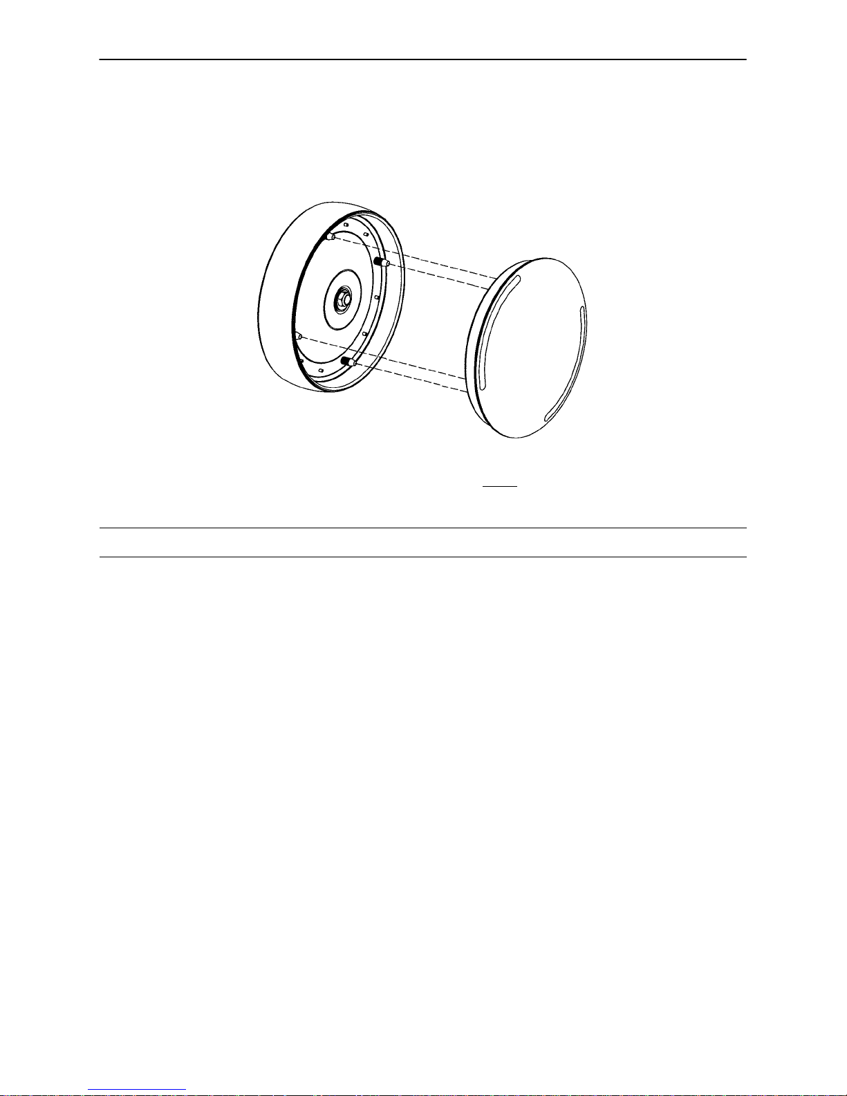
BIG WHEEL HUBCAP REMOVAL
Required Tools:
Large Standard Screwdriver
1. Using a large standard screwdriver, pry evenly around the entire edge of the Big Wheel hubcap until it
pops off the mounting studs on the wheel.
CAUTION
Do not attempt to pull off the hubcap after prying up only one side. Damage to the slots on the hubcap or
the mounting studs on the wheel could result.
2. To reinstall the hubcap, place it on the wheel, aligning the slots in the hubcap with the mounting studs
on the wheel. Press down evenly on the edges of the hubcap until it snaps into place.
LITTER TOP REMOVAL
Required Tools:
1. Using the foot pedal, pump up the litter top to full height.
2. Remove the stretcher mattress
3. Remove the round, black hole plugs from the jack supports at each end of the litter to expose the jack
support tube truss head screws.
4. Using a 1/2” socket, and a 3/8” drive ratchet, remove the truss head screws holding the jack support tubes
to the jack shafts.
1/2” Socket w/Extension 3/8” Drive Ratchet Standard Screwdriver
5. Thread a 7/16−20 fine thread bolt far enough into the top of the jack supports to separate the litter top
from the jack shaft.
6. With the assistance of another person, lift the litter straight up to remove it from the jack shafts and set
it aside.
12
Page 14

Service Information
BIG WHEEL CARRIAGE ASSEMBLY REMOVAL
Required Tools:
1/2” Socket 3/8” Drive Ratchet Needle−Nose Pliers
1. Remove the litter top from the stretcher (see page 12).
2. Lift the base hood off the base frame.
3. With the brake/steer pedal in the steer position, remove the clevis pin and rue ring cotter connecting the
brake rod to the brake rod drive link at each end of the stretcher.
4. Remove the two clevis pins and rue ring cotters connecting the brake rods to the drive arm at the center
of the base near the cam bracket assembly.
5. Pull the brake shafts straight out away from the base.
BIG WHEEL REMOVAL
Required Tools:
Large Standard Screwdriver Small Standard Screwdriver String or Bungee Cords
1. Lift the base hood and separate the Velcro holding it to the base frame. Support the hood from the litter
using bungee cords so it is out of the way.
2. Using a large, standard screwdriver, pop off the big wheel cover.
3. Using a small, standard screwdriver, remove the spiral retaining ring from the groove on the Big Wheel axle.
4. Remove the Big Wheel.
5. Reverse steps 1−4 to reinstall the Big Wheel.
6. Remove the four hex washer head screws holding the cam bracket assembly to the base frame and re-
move the cam bracket assembly.
NOTE
On a base with 4−sided brakes, remove the rue ring cotter and clevis pin connecting the side control big wheel
linkage assembly to the yoke weldment on the end control brake pad at the foot end of the stretcher.
7. Remove the two hex washer head screws holding the carriage weldment to the base frame and remove
the carriage assembly.
8. Reverse steps 1−7 to reinstall the carriage assembly.
13
Page 15

Service Information
BIG WHEEL CAM GAS SPRING DAMPENER REMOVAL
Required Tools:
1/2” Socket 3/8” Drive Ratchet Needle−Nose Pliers
1. Remove the litter top from the stretcher (see page 12).
2. Lift the base hood off the base frame.
3. Remove the two clevis pins and rue ring cotters connecting the brake rods to the drive arm at the center
of the base near the cam bracket assembly.
4. Pull the brake shafts straight out away from the base.
5. Remove the four hex washer head screws holding the cam bracket assembly to the base frame and re-
move the cam bracket assembly.
6. Remove the rue ring cotter from the dampener mounting pin and remove the pin.
7. Lift up on the (patient) left side of the cam bracket and remove the rue ring cotter holding the dampener
to the dampener arm and remove the dampener.
8. Reverse steps 1−7 to install the new dampener.
SIDE CONTROL BIG WHEEL LINKAGE ASSEMBLY REMOVAL
Required Tools:
1/4” Punch Hammer Needle−Nose Pliers
String or Bungee Cords
1. Pump the litter up to full height.
2. Lift the base hood and support it from the litter using string or bungee cords.
3. Using a hammer and 1/4” punch, drive out the slotted spring pin connecting the butterfly “V” pedal on the
patient’s right side to the side control wheel axle.
4. Remove the butterfly “V” pedal and set it aside.
5. Using the hammer and 1/4” punch, drive out the slotted spring pin holding the side control Big Wheel link-
age yoke weldment to the side control wheel axle.
6. Pull straight out on the patient’s left side butterfly “V” pedal and remove the side control wheel axle.
7. Using needle−nose pliers, remove the hair pin cotter and washer holding the toggle pivot plate to the side
control Big Wheel carriage assembly.
8. Remove the rue ring cotter and clevis pin connecting the side control Big Wheel linkage rod end link to
the end control brake rod.
9. Remove the side control Big Wheel linkage assembly and set it aside.
10. Reverse steps 1−9 to reinstall the linkage assembly.
14
Page 16

Service Information
JACK DESCENT RATE ADJUSTMENT
Required Tools:
Screwdriver Bungee Cords (or equivalent)
Adjustment Procedure:
1. Pump the litter up to full height.
2. Lift the base hood, separating the hood from the base frame. Support the hood from the litter using bun-
gee cords so it is out of the way.
3. The descent rate needle valve is located on the base of the jack. Turning the needle valve clockwise,
with a screwdriver, will decrease the rate of descent. Turning it counterclockwise will increase the rate
of descent.
NOTE
The larger percentage of a patient’s weight is located in the torso area. Adjust descent rate accordingly.
4. Remove the bungee cords supporting the base hood and secure the hood to the base frame.
NOTE
The jack descent rate is preset at the factory and adjustment is not recommended.
REMOVAL OF EXCESS AIR (VACUUM) FROM THE HYDRAULIC SYSTEM
1. Verify all hydraulic linkages are secure and operating properly.
2. Using the pump pedal, actuate the system several times to force the air through the system. The jack
should now raise properly.
15
Page 17

Service Information
HEAD END HYDRAULIC JACK REMOVAL
Required Tools:
1. Remove the litter top from the stretcher (see page 12).
2. Using a 1/2” socket with extension and a 3/8” drive ratchet, remove the two hex head screws holding the
jack base to the stretcher base frame.
3. Remove the two hex head screws holding the jack reservoir clamp to the base frame and remove the
clamps.
4. Lift straight up on the pump connecting rod and disconnect the pump piston from the connecting rod.
5. Disconnect the pump pedal swivel from the release pedal mounting plate.
6. Remove the head end release rod from the release valve assembly.
7. Using a 1/2” socket with extension and a 3/8” drive ratchet, remove the two hex head screws holding the
jack base to the stretcher base frame.
8. Lift out the jack assembly.
9. To reinstall the jack, install the bolts on the jack and reservoir clamp but do not tighten them fully.
10. Reinstall the pump connecting rod and release rod.
11. Depress the pump pedal fully (to the floor). This will properly locate the jack onto the base frame.
12. Tighten the bolts on the jack and reservoir clamp.
13. Pump up the litter and apply weight to verify the jacks hold and do not drift.
1/2” Socket w/Extension 3/8” Drive Ratchet
NOTE
The jack descent rate is preset at the factory and adjustment is not recommended.
FOOT END HYDRAULIC JACK REMOVAL (BASE WITH DUAL CONTROLS)
Required Tools:
1/2” Socket 3/8” Drive Ratchet Pliers
1. Remove the litter top from the stretcher (see page 12).
2. Lift the base hood off the base frame.
3. Remove the two hex washer head screws and washers connecting the pump pedal link to the foot end
pump pedal assembly and pump connecting rod.
4. Remove the foot end release rod from the release valve on the jack assembly by dislodging the release
pedal swivel from the pins on the release pedal weldment.
5. Dislodge the jack pump piston from the pump connecting rod.
6. Remove the two hex washer head screws holding the reservoir clamp.
7. Remove the jack assembly.
8. Reverse steps 1−7 to install the new jack.
NOTE
The jack descent rate is preset at the factory and adjustment is not recommended.
16
Page 18

Service Information
FOOT END HYDRAULIC JACK REMOVAL (BIG WHEEL BASE WITH 3−SIDED CONTROLS)
Required Tools:
1/2” Socket 3/8” Drive Ratchet Pliers
1. Remove the litter top from the stretcher (see page 12).
2. Lift the base hood off the base frame.
3. Remove the hair pin cotter and washer connecting the side control Big Wheel linkage toggle pivot plates
to the side control Big Wheel carriage weldment.
4. Remove the rue ring cotter and clevis pin connecting the side control Big Wheel rod end link to the yolk
weldment on the end control brake rod.
5. Remove the Big Wheel carriage assembly (see page 13).
6. Remove the two hex washer head screws and washers connecting the pump pedal link to the foot end
pump pedal assembly and pump connecting rod.
7. Remove the foot end pump pedal return spring.
8. Remove the cotter pin from the center of the foot end pump pedal assembly and slide out the pivot pin.
9. Slide the foot end pump pedal assembly up and over the foot end mounting bracket.
10. Remove the four hex washer head screws fastening the foot end mounting bracket to the base frame
and set the bracket aside.
1 1. Remove the foot end release rod from the release valve on the jack assembly by dislodging the release
pedal swivel from the pins on the release pedal weldment.
12. Dislodge the jack pump piston from the pump connecting rod.
13. Remove the two hex washer head screws holding the reservoir clamp.
14. Remove the jack assembly.
15. Reverse steps 1−11 to install the new jack.
NOTE
The jack descent rate is preset at the factory and adjustment is not recommended.
PNEUMATIC FOWLER ADJUSTMENT
Required Tools:
5/32” Hex Allen Wrench 1/2” Open End Wrench
1. Refer to the pneumatic Fowler assembly drawing on page 73 for parts reference.
2. For easier access, raise the Fowler to 75_ or higher.
3. Using a 1/2” open end wrench, loosen the hex nuts (item E) in the actuator arms on the end of the trip
bar (item M).
4. To adjust the Fowler, use a 5/32” hex Allen wrench to turn the Allen screws (item J) 1 to 2 turns count-
er−clockwise if the Fowler will not move or 1 to 2 turns clockwise if the Fowler will not hold its position.
5. Retighten the hex nuts. Be sure the Fowler travels from flat up to 90_ and down again and holds its position when weight is applied before returning the stretcher to service.
17
Page 19

Service Information
TRANSFER BOARD COUNTERBALANCE ADJUSTMENT
Required Tools:
7/16 Open End Wrench
1. Raise the transfer board to the full up position.
2. Unhook the extension spring at the eye bolt.
3. Using a 7/16 open end wrench, loosen the jam nut at the eye bolt.
4. Adjust the eye bolt to the desired position.
5. Tighten the jam nut.
6. Hook the extension spring to the eye bolt.
7. Allow the transfer board to lower on its own.
8. Repeat steps 1−7 until the desired counterbalance is achieved.
FOLDDOWN SIDERAIL LATCH ADJUSTMENT
Required Tools:
1/8” Hex Allen Wrench
WARNING
The siderail latches are preset at the factory, and do not normally need adjustment. If adjustment must be
done, it is important to follow the procedure below. If adjustment is not done properly, injury to the patient
or user could result.
1. Using a 1/8” hex Allen wrench, adjust the hex Allen screw located on the latch assembly opposite the
latch. Turning the screw clockwise will DECREASE the amount of ”play” in the latching mechanism.
Turning counterclockwise will INCREASE the amount.
NOTE
The amount of ”play” in the siderail, when in full up engaged position, should be approximately 1/8 to 3/16
inches.
CAUTION
Too much ”play” when the siderail is in the full up engaged position will give the siderail the appearance of
being unstable and could also cause premature wearing of the latch system.
Too little ”play” will obstruct the latch and keep it from engaging completely in the full up position, which may
result in damage to the latch and/or injury to the patient or user.
18
Page 20

Quick Reference Replacement Parts List
PART NAME PART NUMBER
Cam Replacement Kit, Big Wheel 1040−700−003. . . . . . . . . . . . . . . . . . . . . . . . . . . . . . . . . . . . . . . . . . . . .
Caster Assembly (1 complete) 0753−010−020. . . . . . . . . . . . . . . . . . . . . . . . . . . . . . . . . . . . . . . . . . . . . . . .
Chartholder 0946−028−100. . . . . . . . . . . . . . . . . . . . . . . . . . . . . . . . . . . . . . . . . . . . . . . . . . . . . . . . . . . . . . . . .
C−Spine Cassette Holder 1001−070−000. . . . . . . . . . . . . . . . . . . . . . . . . . . . . . . . . . . . . . . . . . . . . . . . . . . . .
Defibrillator/Equipment Tray 0926−039−000. . . . . . . . . . . . . . . . . . . . . . . . . . . . . . . . . . . . . . . . . . . . . . . . . .
Defibrillator Tray/Foot Extension 1010−050−100. . . . . . . . . . . . . . . . . . . . . . . . . . . . . . . . . . . . . . . . . . . . . . .
Foot Board/Chartholder Combination 0926−040−100. . . . . . . . . . . . . . . . . . . . . . . . . . . . . . . . . . . . . . . . . . .
Foot Board (1 per package) 0946−029−001. . . . . . . . . . . . . . . . . . . . . . . . . . . . . . . . . . . . . . . . . . . . . . . . . . .
Foot Board (2 per package) 0946−029−100. . . . . . . . . . . . . . . . . . . . . . . . . . . . . . . . . . . . . . . . . . . . . . . . . . .
Hydraulic Jack Assembly, Constant Descent 0753−002−001. . . . . . . . . . . . . . . . . . . . . . . . . . . . . . . . . . . .
Hydraulic Jack Assembly, Variable Descent 0753−002−070. . . . . . . . . . . . . . . . . . . . . . . . . . . . . . . . . . . . .
Instrument/Serving Tray 1052−026−000. . . . . . . . . . . . . . . . . . . . . . . . . . . . . . . . . . . . . . . . . . . . . . . . . . . . . .
I.V. Pole, Standard Removable 0390−025−000. . . . . . . . . . . . . . . . . . . . . . . . . . . . . . . . . . . . . . . . . . . . . . .
I.V. Pole Kit, Permanent 2−Stage, Head and Foot End 0721−400−001. . . . . . . . . . . . . . . . . . . . . . . . . . . .
I.V. Pole, Permanent 3−Stage, Head End 0721−061−000. . . . . . . . . . . . . . . . . . . . . . . . . . . . . . . . . . . . . . .
I.V. Pole, Permanent 3−Stage, Foot End 0721−062−000. . . . . . . . . . . . . . . . . . . . . . . . . . . . . . . . . . . . . . . .
I.V. Pole, Tethered 0721−117−000. . . . . . . . . . . . . . . . . . . . . . . . . . . . . . . . . . . . . . . . . . . . . . . . . . . . . . . . . . .
Mattress, 3” x 24”, Standard 1059−324−140. . . . . . . . . . . . . . . . . . . . . . . . . . . . . . . . . . . . . . . . . . . . . . . . . .
Mattress, 4” x 24”, Standard 1059−424−140. . . . . . . . . . . . . . . . . . . . . . . . . . . . . . . . . . . . . . . . . . . . . . . . . .
Mattress, 3” x 26”, Standard 1059−326−140. . . . . . . . . . . . . . . . . . . . . . . . . . . . . . . . . . . . . . . . . . . . . . . . . .
Mattress, 4” x 26”, Standard 1059−426−140. . . . . . . . . . . . . . . . . . . . . . . . . . . . . . . . . . . . . . . . . . . . . . . . . .
Mattress, 3” x 24”, Enhanced Comfort 0721−248−106. . . . . . . . . . . . . . . . . . . . . . . . . . . . . . . . . . . . . . . . . .
Mattress, 4” x 24”, Enhanced Comfort 0721−247−106. . . . . . . . . . . . . . . . . . . . . . . . . . . . . . . . . . . . . . . . . .
Mattress, 3” x 26”, Enhanced Comfort 1001−048−106. . . . . . . . . . . . . . . . . . . . . . . . . . . . . . . . . . . . . . . . . .
Mattress, 4” x 26”, Enhanced Comfort 1001−047−106. . . . . . . . . . . . . . . . . . . . . . . . . . . . . . . . . . . . . . . . . .
Oxygen Bottle Holder, Upright 1020−030−000. . . . . . . . . . . . . . . . . . . . . . . . . . . . . . . . . . . . . . . . . . . . . . . . .
19
Page 21

Quick Reference Replacement Parts List
PART NAME PART NUMBER
Paint, Touch−Up, Gloss Black, Bottle w/Brush 7000−001−322. . . . . . . . . . . . . . . . . . . . . . . . . . . . . . . . . . .
Paint, Touch−Up, Gloss Black, Spray Can 7000−001−319. . . . . . . . . . . . . . . . . . . . . . . . . . . . . . . . . . . . . .
Paint, Touch−Up, Gray, Bottle w/Brush 7000−001−320. . . . . . . . . . . . . . . . . . . . . . . . . . . . . . . . . . . . . . . . .
Paint, Touch−Up, Gray, Spray Can 7000−001−317. . . . . . . . . . . . . . . . . . . . . . . . . . . . . . . . . . . . . . . . . . . . .
Pneumatic Cylinder 1010−031−078. . . . . . . . . . . . . . . . . . . . . . . . . . . . . . . . . . . . . . . . . . . . . . . . . . . . . . . . . .
Restraint Strap, Ankle 0946−043−100. . . . . . . . . . . . . . . . . . . . . . . . . . . . . . . . . . . . . . . . . . . . . . . . . . . . . . . .
Restraint Straps, Body 0390−019−000. . . . . . . . . . . . . . . . . . . . . . . . . . . . . . . . . . . . . . . . . . . . . . . . . . . . . . .
Restraint Strap, Wrist 0946−044−100. . . . . . . . . . . . . . . . . . . . . . . . . . . . . . . . . . . . . . . . . . . . . . . . . . . . . . . .
Siderail Pad Set 1010−052−000. . . . . . . . . . . . . . . . . . . . . . . . . . . . . . . . . . . . . . . . . . . . . . . . . . . . . . . . . . . . .
20
Page 22
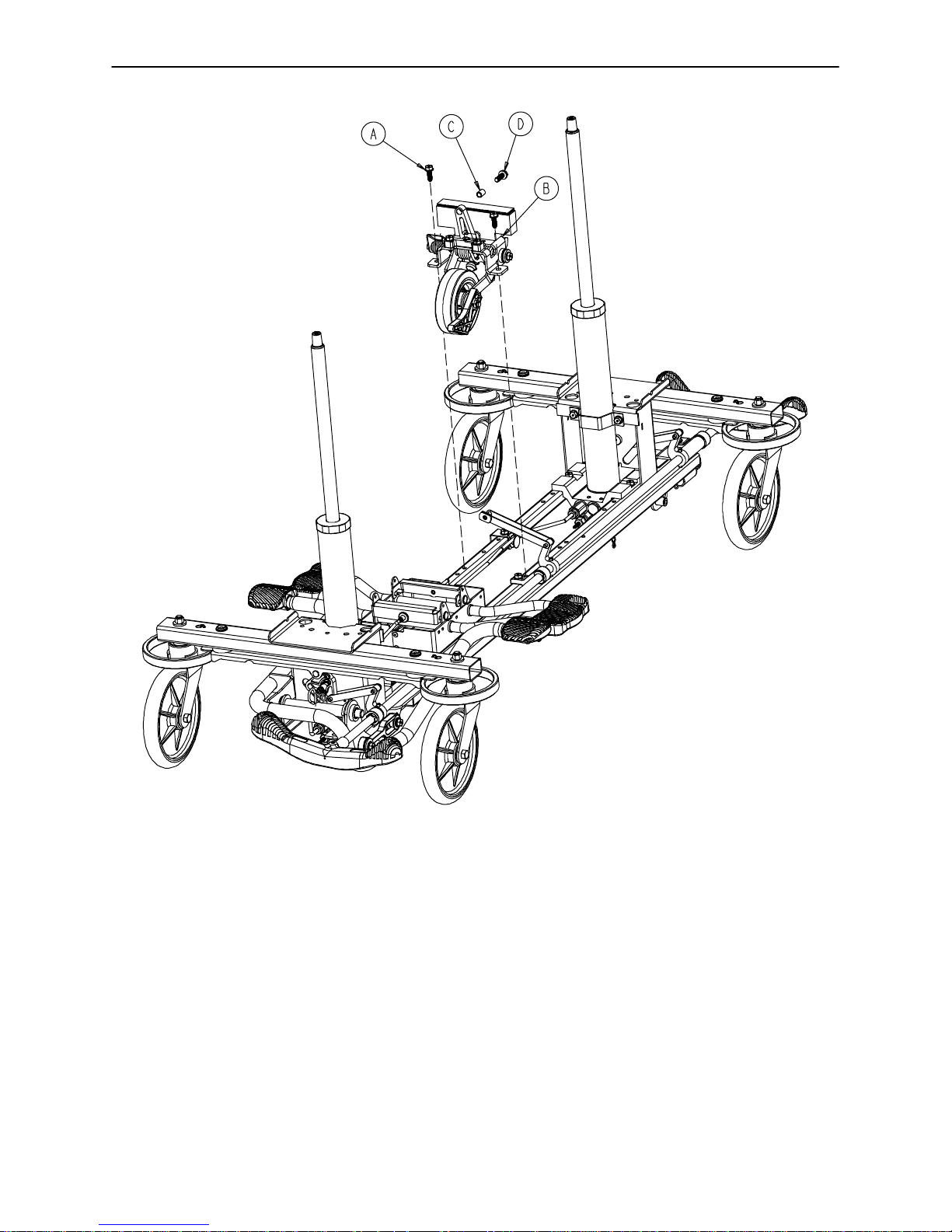
0753−006−110 Retractable Fifth Wheel Base Assembly
Item Part No. Part Name Qty.
A 0023−288−000 Hex Washer Hd. Screw 2
B(page 22) Fifth Wheel Assembly 1
C 0753−006−148 Cam Bearing 1
D 0023−305−000 Hex Hd. Cap Screw 1
21
Page 23
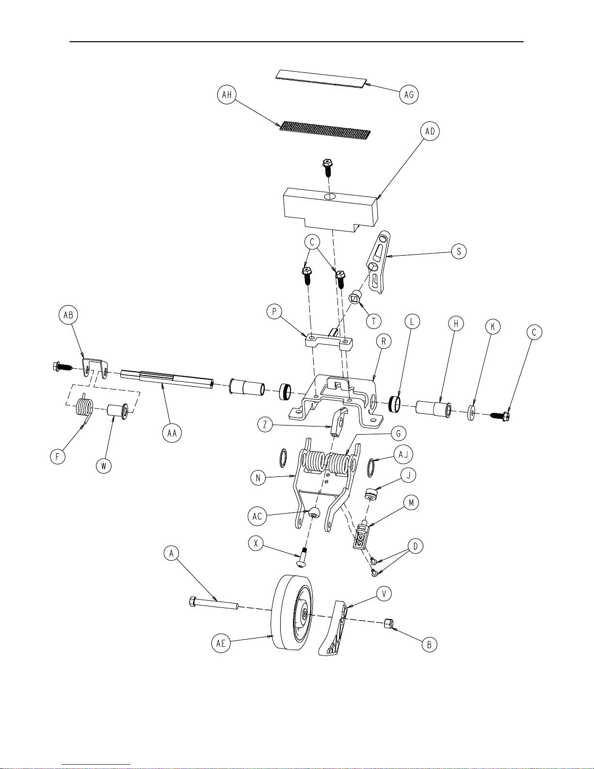
0753−006−130 Fifth Wheel Assembly
22
Page 24

0753−006−130 Fifth Wheel Assembly
Item Part No. Part Name Qty.
A 0003−083−000 Hex Hd. Cap Screw 1
B 0016−035−000 Nylock Hex Nut 1
C 0023−288−000 Hex Washer Hd. Screw 5
D 0025−050−000 Rivet 2
F 0753−006−074 Torsion Spring 1
G 0753−006−075 Torsion Spring 1
H 0753−006−097 Drive Shaft Bearing 2
J 0753−006−106 Dampener 1
K 0753−006−108 Thrust Washer 1
L 0753−006−115 Bearing 2
M 0753−006−120 Bumper Mounting Pin 1
N 0753−006−126 Wheel Bracket 1
P 0753−006−133 Cam Pivot Block 1
R 0753−006−134 Fifth Wheel Mounting Bracket 1
S 0753−006−142 Fifth Wheel Cam 1
T 0753−006−143 Cam Bearing 1
V 0753−006−149 5th Wheel Ramp 1
W 0753−006−152 Spring Spacer 1
X 0753−006−153 Roller Stem 1
Z 0753−006−198 Drive Pin 1
AA 0753−006−223 Drive Shaft 1
AB 0753−006−227 Return Spring Hook 1
AC 0753−006−277 Roller 1
AD 0753−010−045 Hood Standoff 1
AE 1210−001−147 Wheel 1
AG 0753−006−280 Dual Lock 1
AH 0753−006−281 Dual Lock 1
AJ 0011−360−000 Washer 2
23
Page 25
Base Assembly w/Standard Brakes (Fifth Wheel Base)
Assembly part number
0753−003−105
(reference only)
24
Page 26
Base Assembly w/Standard Brakes (Fifth Wheel Base)
Item Part No. Part Name Qty.
A 0005−039−000 Step Bolt 4
B 0011−262−000 Washer 4
C 0016−035−000 Nylock Hex Nut 4
D 0016−049−000 Nylock Hex Nut 2
E 0023−025−000 Hex Washer Hd. Screw 1
F 0023−288−000 Hex Washer Hd. Screw 3
G 0027−012−000 Hitch Pin 2
H 0027−022−000 Rue Ring Cotter 2
J 0028−037−000 External Retaining Ring 4
K 0038−439−000 Extension Spring 4
L 0081−037−000 Plane Bearing 2
M 0753−001−001 Base Frame 1
N(page 26) Brake Rod Assembly 1
P 0753−003−006 Brake Ring 2
R 0753−003−066 Clevis Pin 2
T 0753−003−079 Caster Tube Brake Pin Guide 4
U 0753−003−121 Brake Cushion 4
V 0753−003−230 Bearing Pivot Support 2
W 0753−010−012 Ground Chain 1
X(page 29) Caster Assembly 4
25
Page 27
Brake Rod Assembly
Assembly part number 0753−003−001 (reference only)
Item Part No. Part Name Qty.
A 0026−067−000 Slotted Spring Pin 2
E 0753−003−004 Brake Rod Support 3
F(page 27) Drive Link Assembly 2
G 0753−003−014 Brake Rod 1
H 0753−003−015 Nyliner 3
J 0753−003−099 Butterfly “V” Pedal 2
K (page 28) Drive Link Assembly 1
M 1210−201−335 Red Brake Label 2
N 1210−201−336 Green Steer Label 2
R 0753−003−133 Retainment Spacer 1
26
Page 28

0753−003−010 Drive Link Assembly
Item Part No. Part Name Qty.
B 0753−003−011 Brake Rod Drive Link 1
C 0753−003−061 Brake Cam Drive Link 2
D 0753−003−098 Flat Hd. Semi−Tubular Rivet 2
E 0753−003−102 Brake Cam 1
27
Page 29
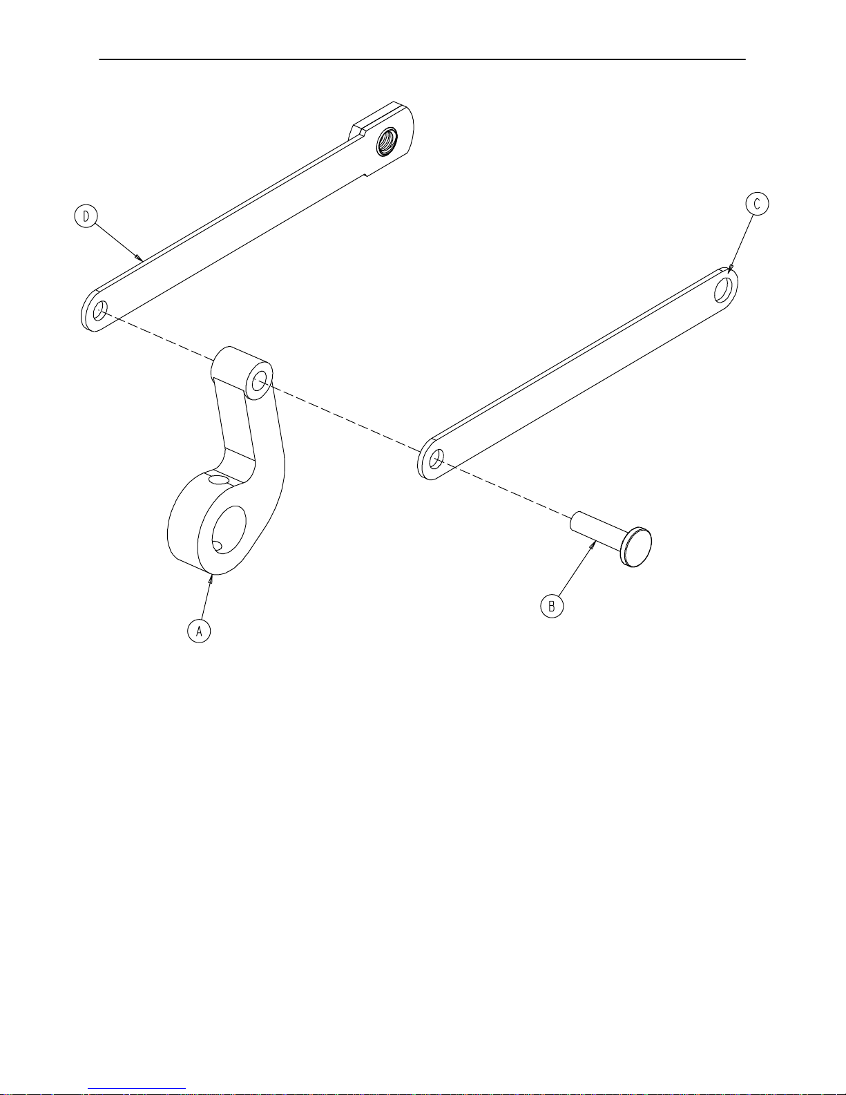
0753−006−135 Drive Link Assembly
Item Part No. Part Name Qty.
A 0753−003−011 Brake Rod Drive Link 1
B 0753−003−098 Semi−Tubular Rivet 1
C 0753−006−122 5th Wheel Cam Drive Link 1
D 0753−006−147 Fifth Wheel Drive Link 1
28
Page 30
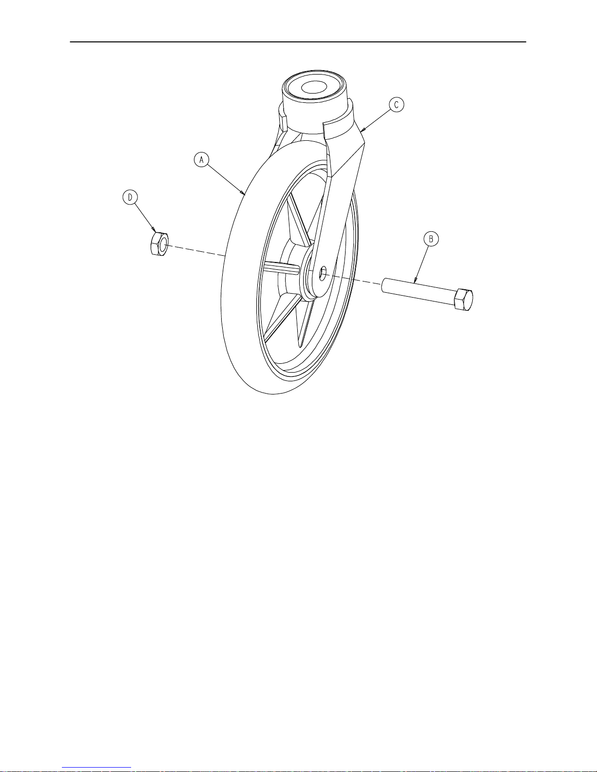
0753−010−020 8” Caster Assembly
Item Part No. Part Name Qty.
A 0715−002−025 Wheel 1
B 0003−099−000 Hex Hd. Cap Screw 1
C 0753−010−021 Caster Horn w/Bearing 1
D 0016−060−000 Centerlock Nut 1
29
Page 31

Base Assembly with 4−Sided Brakes
Assembly part number 0753−003−120
(reference only)
30
Page 32

Base Assembly with 4−Sided Brakes
FOOT ENDHEAD END
Item Part No. Part Name Qty. Item Part No. Part Name Qty.
A 0005−044−000 Step Bolt 4 P 0753−003−066 Clevis Pin 2
B 0011−262−000 Washer 4 R 0753−003−079 Brake Pin Guide 4
C 0016−035−000 Nylock Hex Nut 4 S (page 32) Side Brake Rod Ass’y1
D 0016−049−000 Nylock Hex Nut 2 T 0753−003−121 Brake Cushion 4
E 0023−288−000 Hex Washer Hd. Screw 8 V (page 33) Brake Rod Assembly 1
G 0027−012−000 Hitch Pin 2 W 0753−003−230 Bearing Pivot Support 2
H 0027−020−000 Rue Ring Cotter 1 Y (page 29) Caster Assembly 4
J 0028−037−000 External Retaining Ring 4 Z 0026−340−000 Clevis Pin 1
K 0038−439−000 Extension Spring 4 AA 0027−022−000 Rue Ring Cotter Pin 2
L 0081−037−000 Roller Bearing 2 AB 0753−010−012 Ground Chain 1
M 0753−001−001 Base Weldment 1 AC 0023−025−000 H. Washer Hd. Tap. Scr. 1
N 0753−003−006 Brake Ring Weldment 2
31
Page 33

0753−003−210 Side Control Brake Rod Assembly
Item Part No. Part Name Qty.
A 0026−067−000 Slotted Spring Pin 4
B 0026−340−000 Clevis Pin 1
C 0027−020−000 Rue Ring Cotter 1
D 0753−003−099 Butterfly “V” Pedal 2
E 0753−003−112 Side Control Link 1
F 0753−003−117 Rod End Link 1
G 0753−003−119 Side Control Brake Rod 1
H 0753−003−214 Shaft Support 1
J 1210−201−335 Red Brake Label 2
K 1210−201−336 Green Steer Label 2
32
Page 34

Brake Rod Assembly
Assembly part number 0753−003−125 (reference only)
Item Part No. Part Name Qty.
A 0026−067−000 Slotted Spring Pin 6
D 0753−003−004 Brake Rod Support 4
E(page 27) Drive Link Assembly 2
F 0753−003−014 Brake Rod 1
G 0753−003−015 Brake Rod Nyliner 4
H 0753−003−099 Butterfly “V” Pedal 2
J 0753−003−112 Side Control Link 1
K(page 28) Drive Link Assembly 1
M 1210−201−335 Red Brake Label 2
N 1210−201−336 Green Steer Label 2
P 0753−003−133 Retainment Spacer 1
33
Page 35

Base with Dual Side Hydraulics (Fifth Wheel Base)
HEAD END
Insert pump ram into keyhole
slot on both ends. Lower pump
connecting rod weldment onto
pump ram as shown
Assembly part number 0753−005−200 (reference only)
Insert spring hook thru slots in pump pedal
Attach other end onto jack tower as shown
34
Page 36

Base with Dual Side Hydraulics (Fifth Wheel Base)
Insert spring hook thru
hole in pump connecting
rod. Attach other hook to
return spring as shown
Insert spring hook onto hook
on release pedal. Insert other
hook onto pump connecting
rod as shown.
35
Page 37

Base with Dual Side Hydraulics (Fifth Wheel Base)
See Detail A
Insert head end release
rod into release valve
assembly as shown
DETAIL B
Insert foot end release
rod into release valve
assembly as shown
See Detail B
DETAIL A
Item Part No. Part Name Qty.
A 0011−023−000 Washer 2
B 0014−071−000 Washer 2
C 0023−288−000 Hex Washer Hd. Screw 7
D 0027−031−000 Hair Pin Cotter 1
E 0038−497−000 Extension Spring 3
F 0753−004−014 Head End Release Rod 1
G 0753−004−015 Foot End Release Rod 1
H (page 37) Release Pedal Assembly 1
J 0753−004−132 Release Pedal Swivel 2
K 0753−005−037 Pump Connecting Rod 1
L 0753−005−044 Pump Pedal Bushing 2
M 0753−005−074 Pivot Pin 1
N 0753−005−075 Pump Pedal Link 1
P 0753−005−087 Return Spring Hook 1
R 0753−005−088 Wear Strip 2
T 0753−005−089 Pump Ram Plug 2
U(page 38) Head End Pump Pedal Ass’y1
V 0753−010−215 Release Rod Bracket 1
36
Page 38

0753−004−101 Release Pedal Assembly
Item Part No. Part Name Qty.
A 0025−079−000 Rivet 4
B 0753−004−004 Release Pedal Weldment 2
C 0753−004−029 Release Pedal Standoff 4
D 0753−004−320 Release Pedal Support 1
E 0753−004−321 Release Pedal Support 1
F 1061−201−127 Short Uni Pedal 2
37
Page 39

0753−005−185 Head End Pump Pedal Assembly
Item Part No. Part Name Qty.
A 0026−343−000 Groove Pin 2
B 0715−001−140 Vinyl Tube 1
C 0753−005−044 Pump Pedal Bushing 2
D 0753−005−180 Head End Pump Pedal Weldment 1
E 0753−201−126 Pump Pedal 2
38
Page 40

Base Labeling Assembly
Assembly part number 0753−010−062 (reference only)
Department Label
see page 41
Specification Label
FOOT END
HEAD END
Item Part No. Part Name Qty.
A 0753−010−040 Base Hood 1
B 1040−010−134 Bellows 2
C 0946−201−060 Stryker Logo Label 4
39
Page 41

Base Labeling Assembly, 4−Sided Brakes
Assembly part number 0753−010−063 (reference only)
Department Label
see page 41
Specification Label
FOOT END
HEAD END
Item Part No. Part Name Qty.
A 0753−010−040 Base Hood 1
B 1040−010−134 Bellows 2
C 0946−201−060 Stryker Logo Label 4
H 0753−010−018 Brake/Steer Label, Right 1
J 0753−010−019 Brake/Steer Label, Left 1
40
Page 42

Base Labeling Assembly
Color
Set P/N
RED
0753−010−120
PURPLE
0753−010−121
GREEN
0753−010−122
GRAY
0753−010−123
TEAL
0753−010−124
PINK
0753−010−125
BLUE
0753−010−126
Item D Brake/
Steer, Foot End
0753−010−051 0753−010−055 0753−010−017 0753−010−054 1010−700−015
0753−010−151 0753−010−155 0753−010−170 0753−010−154 1010−700−025
0753−010−251 0753−010−255 0753−010−270 0753−010−254 1010−700−035
0753−010−351 0753−010−355 0753−010−370 0753−010−354 1010−700−045
0753−010−451 0753−010−455 0753−010−470 0753−010−454 1010−700−055
0753−010−551 0753−010−555 0753−010−570 0753−010−554 1010−700−065
0753−010−651 0753−010−655 0753−010−670 0753−010−654 1010−700−075
Item E
Lift/Lower, Left
BASE HOOD DEPARTMENT LABELS
Item F Brake/
Steer, Head End
Item G
Lift/Lower, Right
Litter
Bumper Strip
Department Label Part Number
Emergency 1010−900−215
PACU 1010−900−220
Transport 1010−900−225
Surgery 1010−900−230
Extended Stay 1010−900−235
Maternity 1010−900−240
Endoscopy 1010−900−245
Radiology 1010−900−250
Nuclear Medicine 1010−900−255
Ambulatory Surgery 1010−900−260
G.I. Lab 1010−900−265
Cath. Lab 1010−900−270
Same Day Surgery 1010−900−275
Cardio. 1010−900−280
Ultrasound 1010−900−285
NOTE
All base hood department labels are quantity of two.
41
Page 43

Notes
42
Page 44

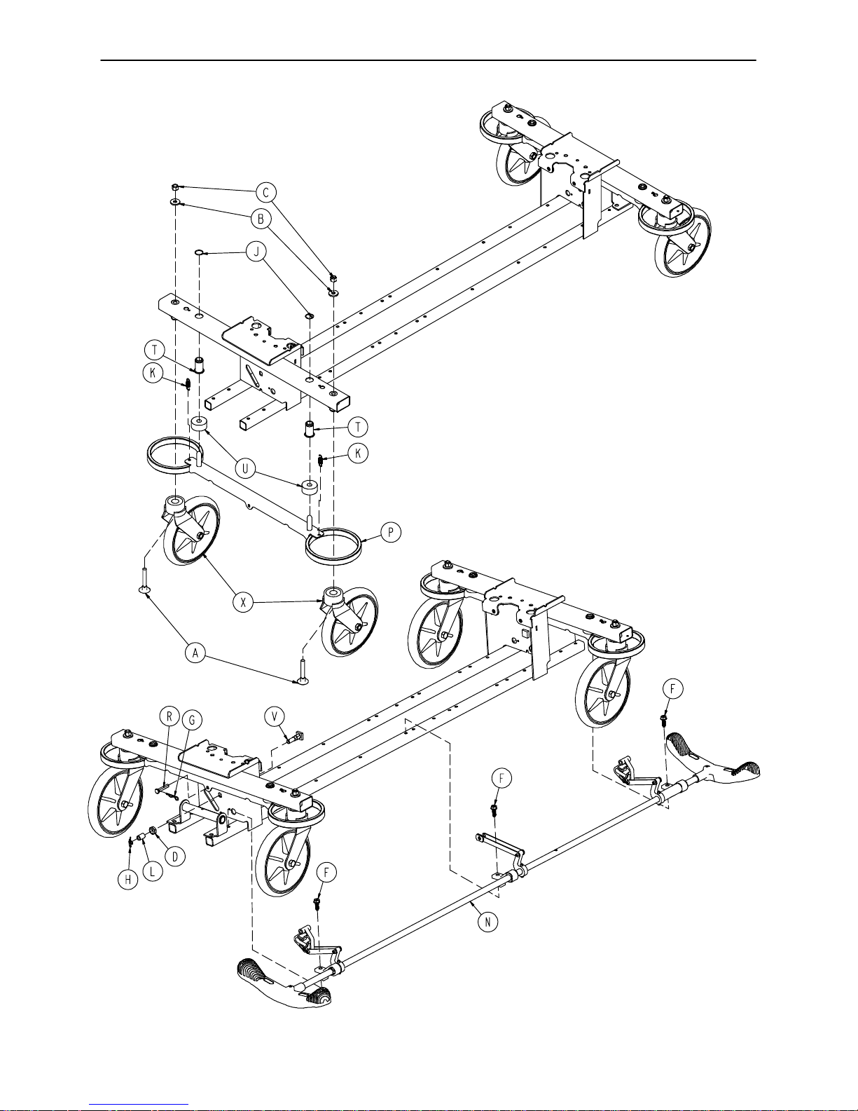
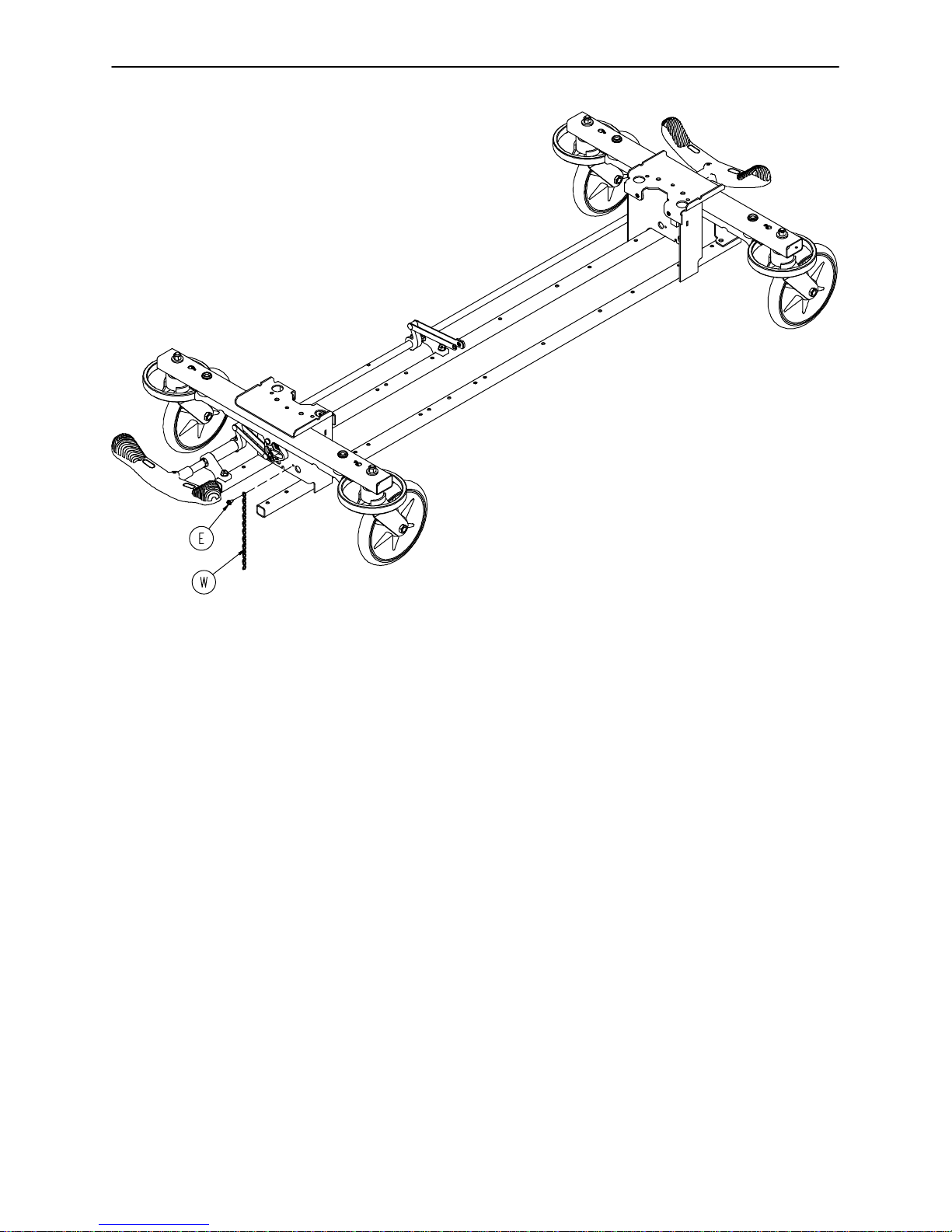
Big Wheel End Control Base Assembly
Assembly part number 1040−015−105 (reference only)
HEAD END
43
Page 45

Big Wheel End Control Base Assembly
DET AIL A
HEAD END
See Detail A
44
Page 46

Big Wheel End Control Base Assembly
Item Part No. Part Name Qty.
A 0021−166−000 Set Screw 2
B 0023−150−000 Hex Washer Hd. Screw 2
C 0023−288−000 Hex Washer Hd. Screw 4
D 0026−273−000 Clevis Pin 4
E 0025−330−000 Clevis Pin 1
F 0027−020−000 Rue Ring Cotter 5
G 0029−007−000 Dual Lock 5
H 0029−009−000 Dual Lock 5
J 0042−020−000 Collar 2
K 0081−330−000 Radial Bearing 1
L(page 49) Brake Rod Assembly 2
M(page 46) Base Assembly w/ Standard Brakes 1
N(page 50) Dual Sided Hydraulics 1
P (page 54) Cam Bracket Assembly 1
R 1040−006−231 Drive Arm 1
T(page 56) Big Wheel Carriage Assembly 1
U 1040−015−007 Carriage Pivot Bushing 2
V 1210−201−251 Insert 4
45
Page 47

Base Assembly w/Standard Brakes (Big Wheel Base)
Assembly part number 1040−003−405
(reference only)
46
Page 48

Base Assembly w/Standard Brakes (Big Wheel Base)
Item Part No. Part Name Qty.
A 0005−039−000 Step Bolt 4
B 0011−262−000 Washer 4
C 0016−035−000 Nylock Hex Nut 4
D 0016−049−000 Nylock Hex Nut 2
E 0023−025−000 Hex Washer Hd. Screw 1
F 0027−012−000 Hitch Pin 2
G 0027−022−000 Rue Ring Cotter Pin 2
H 0028−037−000 External Retaining Ring 4
J 0038−439−000 Extension Spring 4
K 0081−037−000 Plane Bearing 2
L 0753−003−006 Brake Ring 2
M 0753−003−066 Clevis Pin 2
N 0753−003−079 Caster Tube Brake Pin Guide 4
P 0753−003−121 Brake Cushion 4
R 0753−003−230 Bearing Pivot Support 2
T 0753−010−012 Ground Chain 1
U(page 29) Caster Assembly 4
V 1040−001−301 Base Frame 1
W (page 48) Drive Link Assembly 2
47
Page 49

1040−003−185 Drive Link Assembly
Item Part No. Part Name Qty.
A 0753−003−098 Semi−Tubular Rivet 2
B 0753−003−102 Brake Cam 1
C 1040−003−174 Brake Rod Drive Link 1
D 1040−003−076 Cam Drive Link 2
48
Page 50

1040−003−191 Brake Rod Assembly (Big Wheel Base)
Item Part No. Part Name Qty.
A 0026−067−000 Slotted Spring Pin 1
B 1040−003−113 Brake Rod 1
C 0753−003−099 Butterfly “V” Pedal 1
49
Page 51

Base with Dual Side Hydraulics (Big Wheel Base)
Assembly part number 1040−005−400 (reference only)
Insert pump ram into keyhole
slot on both ends. Lower pump
connecting rod weldment onto
pump ram as shown. Insert
item P to retain pump
connecting rod.
0753−002−025 Constant Descent Jacks
0753−002−080 Variable Descent Jacks
50
Page 52

Base with Dual Side Hydraulics (Big Wheel Base)
Insert spring hook into hook on
release pedal assembly. Insert
other hook into pump connecting
rod weldment as shown.
Insert spring hook thru hole in
pump connecting rod weldment
Attach other hook to return
spring hook as shown.
51
Page 53

Base with Dual Side Hydraulics (Big Wheel Base)
Insert head end release
rod into release valve
assembly as shown
SEE DETAIL B
DETAIL A
Insert foot end release
rod into release valve
assembly as shown
SEE DETAIL A
DETAIL B
Item Part No. Part Name Qty.
A 0011−023−000 Washer 2
B 0014−071−000 Washer 2
C 0023−288−000 Hex Washer Hd. Screw 7
D 0027−031−000 Hair Pin Cotter 1
E 0038−497−000 Extension Spring 3
F 0753−004−014 Head End Release Rod 1
G 0753−004−132 Release Pedal Swivel 2
H(page 37) Release Pedal Assembly 1
J 0753−005−037 Pump Connecting Rod 1
K 0753−005−044 Pump Pedal Bushing 2
L 0753−005−074 Pivot Pin 1
M 0753−005−075 Pump Pedal Link 1
N 0753−005−088 Wear Strip 2
P 0753−005−089 Pump Ram Plug 2
R(page 38) Head End Pump Pedal Ass’y1
T 1040−004−015 Foot End Release Rod 1
U 1040−010−215 Release Rod Bracket 1
52
Page 54

Notes
53
Page 55

Cam Bracket Assembly
Assembly part number 1040−006−201 (reference only)
3
54
Page 56

Cam Bracket Assembly
Item Part No. Part Name Qty.
A 0014−004−000 Washer 1
B 0014−063−000 Washer 2
C 0023−262−000 Clevis Pin 2
D 0026−330−000 Clevis Pin 1
E 0026−341−000 Clevis Pin 2
F 0026−349−000 Clevis Pin 1
G 0027−020−000 Rue Ring Cotter 5
H 0027−025−000 Rue Ring Cotter 2
J 0081−400−000 Needle Bearing 1
K 0081−634−000 Needle Bearing 1
L 1040−006−209 Dampener 1
M 1040−006−141 Cam Pivot 1
N 1040−006−144 Drive Link 1
P 1040−006−163 Dampener Arm 1
R 1040−006−171 Dampener Roller 1
T 1040−006−221 Cam Bracket 1
U 1040−006−313* Lift Cam 1
V 1040−006−146 Torsion Spring 1
* Cam Replacement Kit − part number 1040−700−003.
55
Page 57

Big Wheel Carriage Assembly
Assembly part number 1040−015−101 (reference only)
Item Part No. Part Name Qty.
A 0014−004−000 Washer 1
B 0026−341−000 Clevis Pin 1
C 0027−020−000 Rue Ring Cotter 1
D 0028−330−000 Spiral Retaining Ring 3
E 0081−011−000 Needle Bearing 1
F 1040−015−006 Carriage Return Spring 1
G 1040−015−030 Cover w/Counterweight 2
H 1040−015−038 Washer 1
J 1040−015−053 Carriage Spring Retainer 1
K 1040−015−110 Carriage Weldment 1
L 1040−020−122 Cam Follower Pivot Pin 1
M 1040−020−128 Lift Cam Roller 1
N 1040−020−129 Carriage Roller Guide 1
P 1210−301−619 Wheel Assembly 2
56
Page 58

Big Wheel 4−Sided Control Base
Assembly part number 1040−025−105 (reference only)
HEAD END
57
Page 59

Big Wheel 4−Sided Control Base
DETAIL A
See Detail A
HEAD END
58
Page 60

Big Wheel 4−Sided Control Base
Item Part No. Part Name Qty.
A 0021−166−000 Set Screw 2
B 0023−150−000 Hex Washer Hd. Screw 2
C 0023−288−000 Hex Washer Hd. Screw 4
D 0026−273−000 Clevis Pin 5
E 0026−330−000 Clevis Pin 1
F 0027−020−000 Rue Ring Cotter 6
G 0029−007−000 Dual Lock 5
H 0029−009−000 Dual Lock 5
J 0042−020−000 Collar 2
K 0081−330−000 Radial Bearing 1
L(page 49) Brake Rod Assembly 2
M(page 46) Base Assembly w/ Standard Brakes 1
N(page 50) Dual Sided Hydraulics 1
P(page 54) Cam Bracket Assembly 1
R 1040−006−231 Drive Arm 1
T 1040−015−007 Carriage Pivot Bushing 2
U(page 60) Side Control Big Wheel Carriage Ass’y1
V 1040−025−026 Brake Rod Bushing 1
W 1210−201−251 Insert 3
59
Page 61

Side Control Big Wheel Carriage Assembly
Assembly part number 1040−025−101 (reference only)
60
Page 62

Side Control Big Wheel Carriage Assembly
Item Part No. Part Name Qty.
A 0011−148−000 Washer 2
B 0011−525−000 Washer 2
C 0014−004−000 Washer 1
D 0026−341−000 Clevis Pin 1
E 0026−342−000 Groove Pin 3
F 0027−020−000 Rue Ring Cotter 1
G 0028−166−000 External Retaining Ring 1
H 0028−330−000 External Retaining Ring 1
J 0081−011−000 Needle Bearing 4
K 0081−175−000 Thrust Bearing 2
L 0753−003−099 Butterfly “V” Pedal 2
M 0753−003−219 Side Control Brake Rod 1
N 1040−015−006 Carriage Return Spring 1
P 1040−015−038 Washer 1
R 1040−015−053 Carriage Spring Retainer 1
T 1040−020−122 Cam Follower Pivot Pin 1
U 1040−020−128 Lift Cam Roller 1
V 1040−020−129 Carriage Roller Guide 1
W(page 62) Side Control Linkage Ass’y1
X 1040−025−014 Side Control Wheel Spacer 2
Y 1040−025−017 Side Control Pedal Spacer 2
AA 1040−025−030 Cover w/Counterweight 2
AB 1040−025−110 4−Sided Carriage 1
AC 1210−201−335 Red Brake Label 2
AD 1210−201−336 Green Steer Label 2
AE 1210−301−619 Wheel Assembly 2
61
Page 63

1040−025−010 Side Control Big Wheel Linkage Ass’y
Item Part No. Part Name Qty.
A 0753−003−098 Flat Hd. Semi−Tubular Rivet 4
B 0753−003−117 Rod End Link 1
C 1040−025−011 Main Link 1
D 1040−025−013 Toggle Pivot Plate 2
E 1040−025−016 Main Link Cover 2
F 1040−025−020 Yoke Weldment 2
G 1040−025−018 Toggle Pivot Spacer 1
H 1040−025−027 Link Spacer 2
62
Page 64

Base Labeling Assembly − Big Wheel Base
Assembly part number 1040−015−400 (reference only)
Specification Label
Department Label
see page 64
FOOT END
HEAD END
Item Part No. Part Name Qty.
A 1040−010−134 Bellows 2
B 1040−015−404 Base Hood 1
C 0946−201−060 Stryker Logo Label 4
63
Page 65

Base Labeling Assembly
Color
Set P/N
RED
0753−010−120
PURPLE
0753−010−121
GREEN
0753−010−122
GRAY
0753−010−123
TEAL
0753−010−124
PINK
0753−010−125
BLUE
0753−010−126
Item D Brake/
Steer, Foot End
0753−010−051 0753−010−055 0753−010−017 0753−010−054 1010−700−015
0753−010−151 0753−010−155 0753−010−170 0753−010−154 1010−700−025
0753−010−251 0753−010−255 0753−010−270 0753−010−254 1010−700−035
0753−010−351 0753−010−355 0753−010−370 0753−010−354 1010−700−045
0753−010−451 0753−010−455 0753−010−470 0753−010−454 1010−700−055
0753−010−551 0753−010−555 0753−010−570 0753−010−554 1010−700−065
0753−010−651 0753−010−655 0753−010−670 0753−010−654 1010−700−075
Item E
Lift/Lower, Left
BASE HOOD DEPARTMENT LABELS
Item F Brake/
Steer, Head End
Item G
Lift/Lower, Right
Litter
Bumper Strip
Department Label Part Number
Emergency 1010−900−215
PACU 1010−900−220
Transport 1010−900−225
Surgery 1010−900−230
Extended Stay 1010−900−235
Maternity 1010−900−240
Endoscopy 1010−900−245
Radiology 1010−900−250
Nuclear Medicine 1010−900−255
Ambulatory Surgery 1010−900−260
G.I. Lab 1010−900−265
Cath. Lab 1010−900−270
Same Day Surgery 1010−900−275
Cardio. 1010−900−280
Ultrasound 1010−900−285
NOTE
All base hood department labels are quantity of two.
64
Page 66

0753−002−080 Variable Descent Hydraulic Jack Option
0753−001−001 Base Frame Weldment
Item Part No. Part Name Qty.
A 0023−288−000 Hex Washer Hd. Screw 8
B 0753−002−070 Variable Descent Jack Assembly 2
C 0753−010−007 Reservoir Clamp 2
65
Page 67

0753−002−025 Constant Descent Hydraulic Jack Option
0753−001−001
Base Frame Weldment
Item Part No. Part Name Qty.
A 0023−288−000 Hex Washer Hd. Screw 8
B 0753−002−001 Constant Descent Jack Ass’y2
C 0753−010−007 Reservoir Clamp 2
66
Page 68

Litter Assembly
Assembly part number 0721−301−010 (reference only)
Detail of
Siderail Latch
HEAD END
67
Page 69

Litter Assembly
HEAD END
68
Page 70

Litter Assembly
Item Part No. Part Name Qty.
A 0003−359−000 Hex Hd. Cap Screw 8
B 0004−135−000 But. Hd. Cap Screw 4
C 0004−136−000 But. Hd. Cap Screw 14
D 0004−330−000 Soc. Hd. Cap Screw 4
E 0011−077−000 Washer 4
F 0011−360−000 Washer 2
G 0014−021−000 Washer 12
H 0016−118−000 Hex Nut 10
J 0016−117−000 Stover Hex Lock Nut 4
K 0021−105−000 Set Screw 2
L 0023−104−000 Pan Hd. Hi−Lo Tapping Screw 8
M 0004−363−000 But. Hd. Cap Screw 2
N 0025−038−000 Dome Hd. Rivet 20
P 0025−122−000 Dome Hd. Rivet 24
R 0028−023−000 External Retaining Ring 2
S 0037−010−000 Hole Plug 2
T 0037−059−000 Hole Plug 2
W 0037−074−000 Hole Plug 6
Y 0038−220−000 Compression Spring 2
Z 0721−026−066 Pivot Screw 14
AA 0721−026−068 Upright Cradle 6
AB 0721−026−069 Upright Sleeve 4
AC 0721−026−074 Lock Handle 2
AD (page 70) Siderail Assembly, Right 1
AE (page 70) Siderail Assembly, Left 1
AF 0721−031−065 Hole Plug 4
AG 0721−201−020 Litter Frame Weldment 1
AH 0753−010−036 Support Tube, Head End 1
AJ 0753−010−042 Support Tube, Foot End 1
AK 0753−010−043 Jack Supt. Tube, Hd. End 2
AL 0753−010−044 Stationary Foot Section Skin 1
AM 0926−400−142 Bumper 4
AN 0938−001−401 Collar 2
AP 1001−040−012 Foot Board Receptacle 2
AR 1001−201−029 Nylon Insert 2
AS 1001−401−030 Trend Support 2
AT 1010−026−069 Lock Support 2
AW 1010−026−080 Lock Housing, Left 1
AX 1010−026−081 Lock Housing, Right 1
AY 1010−201−027 Bumper Channel 2
AZ 1010−201−238 Corner Cover, Slot 2
BA 1010−201−239 Corner Cover, Hole 2
BB 1210−800−008 Patent Label 1
69
Page 71

Assembly part numbers
0721−026−096 (Right)
0721−026−097 (Left)
Siderail Assembly, Right & Left
J
(Left Side Shown)
Item Part No. Part Name Qty.
A 1010−026−015 Top Rail 1
B 1010−026−083 Upright 4
C 1010−026−084 Upright, Bent 1
D 1010−026−082 Spacer 6
E 0025−106−000 Semi−Tubular Rivet 6
F 1010−026−010 Round Hole Plug 4
H 1010−026−085 Upright, Latch 1
J 1010−026−012 Bent Spindle Stop 1
70
Page 72

Manual Fowler Assembly
Assembly part number 0721−232−010
(reference only)
P
R
HEAD END
Item Part No. Part Name Qty.
A 0721−232−019 Brace Assembly 1
B 0014−002−000 Nylon Flat Washer 6
C 0003−357−000 Hex Hd. Cap Screw 2
D 0016−118−000 Nylock Hex Nut 18
E 0003−355−000 Hex Hd. Cap Screw 6
F 1001−032−022 Position Bar Rest 2
H 0004−135−000 But. Hd. Cap Screw 10
J 0016−003−000 Lock Nut 4
K 1001−032−026 Manual Fowler Rest 2
L 0004−169−000 But. Hd. Cap Screw 4
M 1001−032−023 Tab Assembly 2
N 1001−032−028 Riser Assembly 2
P 0721−231−012 Fowler Skin 1
R 0721−231−013 Fowler Tube 1
71
Page 73

Pneumatic Fowler Assembly
Assembly part number 0721−231−110 (reference only)
HEAD END
Item Part No. Part Name Qty.
A 0004−182−000 Hex Soc. But. Hd. Cap Screw 2
B 0004−183−000 Hex Soc. But. Hd. Cap Screw 2
C 0011−179−000 Washer 2
D 0014−021−000 Washer 8
E 0015−060−000 Hex Jam Nut 2
F 0016−116−000 Hex Nut 2
H 0016−117−000 Hex Nut 2
J 0023−256−000 Self−Tapping Screw 2
K 0025−122−000 Blind Rivet 9
L(page 73) Pneumatic Fowler Assembly 1
M 1010−031−078 Gas Cylinder 2
N 1211−031−031 Pneumatic Fowler Rest 2
72
Page 74

Pneumatic Fowler Assembly
Assembly part number
0721−231−120 (reference only)
Item Part No. Part Name Qty.
A 0004−135−000 But Hd. Cap Screw 6
B 0004−161−000 Hex Soc. But. Hd. Cap Screw 2
C 0007−071−000 Truss Hd. Mach. Screw 4
D 0015−037−000 Jam Nut 2
E 0015−050−000 Hex Nut 2
F 0016−118−000 Stover Lock Nut 12
H 0021−125−000 Set Screw 2
J 0021−126−000 Set Screw 2
K 0721−231−012 Fowler Skin 1
L 0721−231−013 Fowler Tube 1
M 0721−231−118 Trip Bar Assembly 1
N 1001−001−036 Hole Plug 2
P(page 74) Outer Housing Ass’y, Right 1
R(page 74) Outer Housing Ass’y, Left 1
73
Page 75

Pneumatic Fowler Outer Housing Assembly
Assembly part number 1210−031−106 (Right)
Item Part No. Part Name Qty.
A 0025−144−000 Semi−Tubular Rivet 1
B 1210−031−103 Pivot Tab 1
C 1210−031−104 Outer Housing, Right 1
Assembly part number 1210−031−107 (Left)
Item Part No. Part Name Qty.
A 0025−144−000 Semi−Tubular Rivet 1
B 1210−031−103 Pivot Tab 1
C 1210−031−105 Outer Housing, Left 1
74
Page 76

0721−239−010 Optional Short Transfer System Assembly
HEAD END
Item Part No. Part Name Qty.
A(page 76) Transfer System Ass’y, Rt. 1
B(page 77) Transfer System Ass’y, Lt. 1
C 0010−011−000 Eye Bolt 2
D 0038−218−000 Tension Spring 2
E 1010−224−025 Spring Retainer 2
F 0003−359−000 Hex Hd. Cap Screw 8
G 0011−180−000 Flat Washer 8
H 0016−118−000 Nylock Hex Nut 12
J 0015−021−000 Jam Nut 4
K 0003−356−000 Hex Hd. Cap Screw 4
75
Page 77

1010−232−010 Short Transfer Board Assembly, Right
Item Part No. Part Name Qty.
A 1010−032−098 Pivot 2
B 1010−224−033 Connecting Link Ass’y, Rt. 1
C 1010−232−016 Pivot Arm Ass’y, Right 2
D 1020−032−100 Transfer Board Ass’y1
E 0011−224−000 Nylon Flat Washer 4
F 0014−021−000 Nylon Flat Washer 2
G 0016−118−000 Nylock Hex Nut 2
H 0028−093−000 Retaining Ring 4
J 0003−356−000 Hex Hd. Cap Screw 2
K 0025−157−000 Blind Rivet 2
L 0721−024−046 Label 1
M 1211−132−025 Pivot Sleeve 2
76
Page 78

1010−232−011 Short Transfer Board Assembly, Left
Item Part No. Part Name Qty.
A 1010−032−098 Pivot 2
B 1010−224−033 Connecting Link Ass’y1
C 1010−232−017 Pivot Arm Ass’y, Lt. 2
D 1020−032−100 Transfer Board Ass’y1
E 0011−224−000 Nylon Flat Washer 4
F 0014−021−000 Nylon Flat Washer 2
G 0016−118−000 Nylock Hex Nut 2
H 0028−093−000 Retaining Ring 4
J 0003−356−000 Hex Hd. Cap Screw 2
K 0025−157−000 Blind Rivet 2
L 0721−024−046 Label 1
M 1211−132−025 Pivot Sleeve 2
77
Page 79

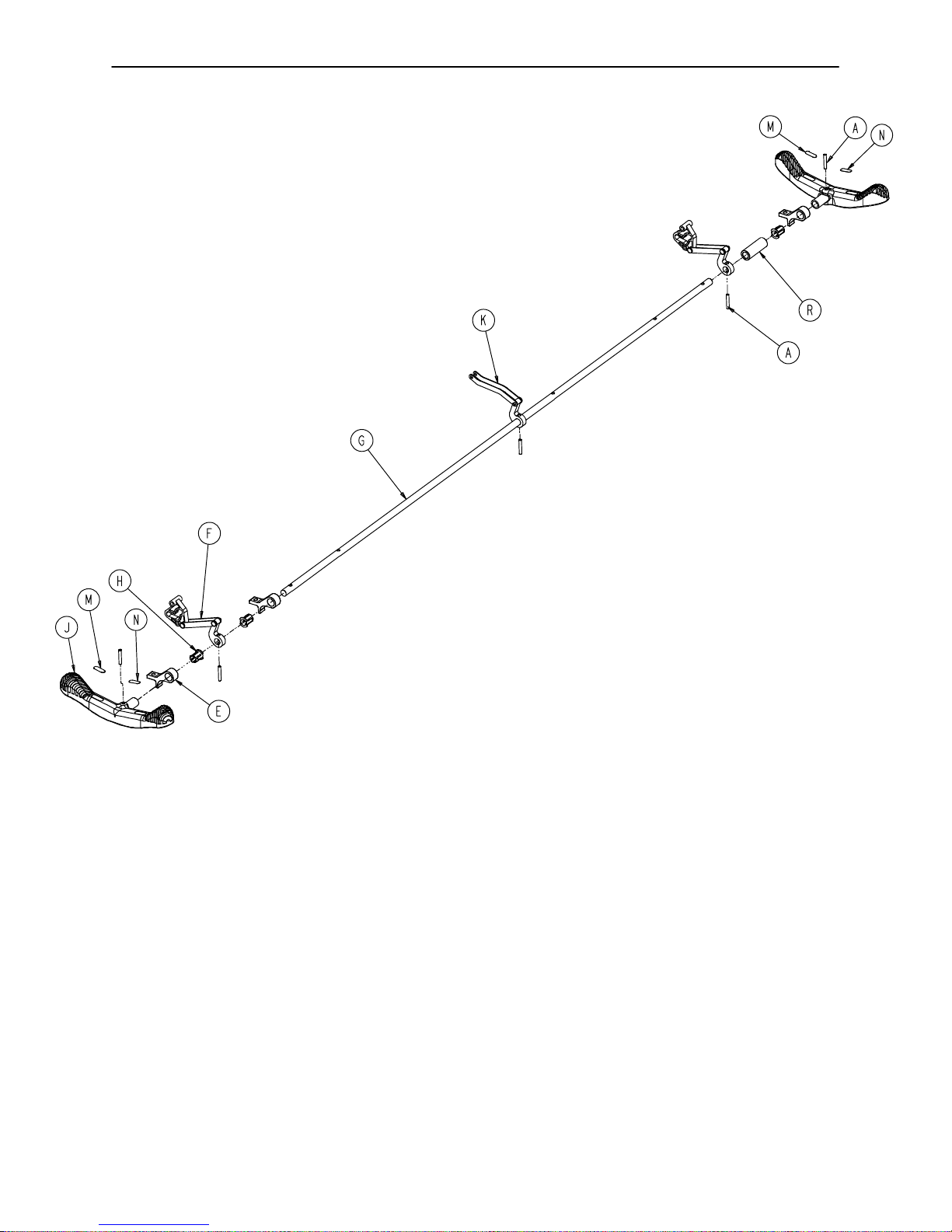
0721−234−010 Optional Long Transfer System Assembly
HEAD END
Item Part No. Part Name Qty.
A(page 80) Transfer System Ass’y, Rt. 1
B(page 79) Transfer System Ass’y, Lt. 1
C 0010−011−000 Eye Bolt 2
D 0038−218−000 Tension Spring 2
E 0721−224−025 Spring Retainer, Rt. 1
F 0003−359−000 Hex Hd. Cap Screw 12
G 0011−180−000 Flat Washer 8
H 0016−118−000 Nylock Hex Nut 12
J 0015−021−000 Jam Nut 2
K 0721−224−024 Spring Retainer, Lt. 1
L 0721−024−061 Pivot Arm Rest 2
M 0025−179−000 Pop Rivet 4
N 0721−201−017 Riser Tube (not shown) 2
78
Page 80

0721−234−012 Long Transfer Board Assembly, Left
M
H
J
M
Item Part No. Part Name Qty.
A 0721−024−055 Transfer Board Ass’y1
B 0721−024−046 Label 1
C 0721−224−016 Long Pivot, Machined 2
D 0721−224−033 Connecting Link Ass’y1
E 0721−232−017 Pivot Arm Ass’y, Lt. 2
F 0028−093−000 Retaining Ring 4
H 0003−050−000 Hex Hd. Cap Screw 2
J 0011−224−000 Nylon Flat Washer 4
K 0014−021−000 Nylon Flat Washer 2
L 0004−156−000 Soc. Hd. Cap Screw 2
M 0016−028−000 Nylock Hex Nut 2
79
Page 81

0721−234−013 Long Transfer Board Assembly, Right
B
M
K
C
F
J
J
H
D
E
L
K
C
H
F
A
M
J
E
L
Item Part No. Part Name Qty.
A 0721−024−055 Transfer Board Ass’y1
B 0721−024−046 Label 1
C 0721−224−016 Long Pivot, Machined 2
D 0721−224−033 Connecting Link Ass’y, Rt. 1
E 0721−232−016 Pivot Arm Ass’y, Right 2
F 0028−093−000 Retaining Ring 4
H 0003−050−000 Hex Hd. Cap Screw 2
J 0011−224−000 Nylon Flat Washer 4
K 0014−021−000 Nylon Flat Washer 2
L 0004−156−000 Soc. Hd. Cap Screw 2
M 0016−028−000 Nylock Hex Nut 2
80
Page 82

0390−025−022 Standard, Removable IV Pole Assembly
Item Part No. Part Name Qty.
A 0024−023−000 Plastic Knob 1
B 0390−003−053 Double IV Ass’y1
C 0393−003−043 Tube Assembly 1
D 0004−496−000 Soc. Hd. Cap Screw 1
81
Page 83

0721−117−000 Optional Tethered I.V. Assembly
HEAD END
Item Part No. Part Name Qty.
A 0025−133−000 Pop Rivet 2
D 0025−171−000 Rivet 1
E 0034−022−000 Cable Clamp 1
F 1001−159−042 I.V. Plug 1
H(page 83) Tethered I.V. Pole Assembly 1
J 1211−117−021 Backing Plate 1
K 1211−117−022 I.V. Clip 1
82
Page 84

Tt
1211−117−010 Tethered I.V. Pole Assembly
Item Part No. Part Name Qty.
A 0052−017−000 Spacer 2
B 1211−117−020 Cable Assembly 1
C 0926−400−062 Stop Sleeve 1
D 1010−059−016 I.V. Hook 2
E 1211−117−011 Extension Rod 1
F 1211−117−012 Base Tube Weldment 1
G 0004−495−000 Low Hd. Soc. Hd. Cap Screw 1
H 1211−117−016 Knob 1
J 0014−020−000 Nylon Washer 1
K 0004−232−000 Button Hd. Cap Screw 1
83
Page 85

721−400−001 Optional 2−Stage I.V. Assembly
Assembly part number 0721−280−000 & 0721−281−000
(reference only)
HEAD END
FOOT END
Item Part No. Part Name Qty
A(page 85) I.V. Pole Assembly 1
B 1001−259−103 I.V. Pivot 1
C 0016−118−000 Fiberlock Nut 3
E 0004−452−000 But. Hd. Cap Screw 1
F 0003−356−000 Hex Hd. Cap Screw 3
G 0016−116−000 Flexlock Nut 1
J 1001−259−042 I.V. Plug 1
84
Page 86

1211−210−010 Optional 2−Stage I.V. Pole Assembly
Item Part No. Part Name Qty.
A 0008−031−000 Soc. Hd. Cap Screw 1
B 0052−017−000 Washer 2
C 0926−400−162 Spacer 1
D 1211−210−029 2nd Stage Assembly 1
E 1001−359−013 Dampener 1
F 1001−159−028 Base Tube 1
G 1010−059−016 I.V. Hook 2
H(page 86) I.V. Pole Latch 1
J 1001−359−112 Pivot 1
85
Page 87

1211−210−026 I.V. Pole Latch Assembly
Item Part No. Part Name Qty.
A 0028−167−000 Retaining Ring 1
B 0031−004−000 Steel Ball 2
C 0038−392−000 Crest−to−Crest Spring 1
D 1211−091−034 Release Label 1
E 1211−110−018 I.V. Latch Seal 1
F 1211−110−020 Washer 2
G 1211−110−021 I.V. Latch Locking Pin 2
H 1211−110−022 I.V. Latch Guide 1
J 1211−110−024 I.V. Latch O.D. Housing 1
K 1211−110−035 Washer 1
L 1211−110−036 Self−Tapping Screw 2
M 1211−210−023 I.V. Latch I.D. Housing 1
86
Page 88

0721−061−000 Optional 3−Stage I.V. Assembly, Head
0721−062−000 Optional 3−Stage I.V. Assembly, Foot
FOOT END
HEAD END
Item Part No. Part Name Qty.
A(page 88) I.V. Pole Assembly 1
B 1001−259−103 I.V. Pivot 1
C 0016−118−000 Fiberlock Nut 3
E 0004−452−000 But. Hd. Cap Screw 1
F 0003−356−000 Hex Hd. Cap Screw 3
G 0016−116−000 Flexlock Nut 1
H 1001−259−042 Plug 1
87
Page 89

1211−211−010 Optional 3−Stage I.V. Pole Assembly
Item Part No. Part Name Qty.
A 0007−004−000 Truss Hd. Machine Screw 1
C 0026−076−000 Roll Pin 1
D 0052−017−000 Spacer 2
E 1211−210−031 2nd Stage Assembly 1
F 0926−400−162 Spacer 1
G(page 89) 3rd Stage Assembly 1
H 1001−161−023 Base Tube 1
J 1010−059−016 I.V. Hook 2
K 1010−061−014 Collar 1
L(page 86) I.V. Pole Latch 1
M 1211−110−016 Threaded Adaptor 1
N 1001−359−013 Dampener 1
P 1001−359−014 Dampener 1
R 1001−359−112 Pivot 1
88
Page 90

3−Stage I.V. Pole 3rd Stage Assembly
Assembly part number 1211−110−032
(reference only)
NOTE
Item F, part number 1010−061−018 is left hand thread.
When removing it, turn clockwise to loosen it.
Item Part No. Part Name Qty.
A 0031−021−000 Ball 6
B 0038−303−000 Compression Spring 1
C 1010−061−013 Ball Retainer 1
D 1010−061−016 Retaining Shaft 1
E 1010−061−017 Thumb Knob 1
F 1010−061−018 Hand Guard 1
G 1211−110−117 Nut 1
H 1211−110−033 3rd Extension Rod 1
89
Page 91

1001−070−000 C−Spine Cassette Holder Assembly
Item Part No. Part Name Qty.
A 1010−070−025 I.V. Adaptor 2
B 1010−070−018 Specification Label 1
C 0011−447−000 Flat Washer 2
D 0004−054−000 But. Hd. Cap Screw 2
E(page 91) Support Pole Assembly 1
F(page 92) Storage Bracket Ass’y1
G 0016−118−000 Nylock Nut 4
H 0003−356−000 Hex Hd. Cap Screw 2
J 1001−070−011 Attachment Bracket 1
K 0003−355−000 Hex Hd. Cap Screw 2
90
Page 92

1010−070−010 C−Spine Support Pole Assembly
A
A
View
A−A
Item Part No. Part Name Qty.
A 1010−070−033 Support Tube Cap 1
B 0026−006−000 Roll Pin 1
C 1010−070−034 Support Arm Weldment 1
D 1010−070−042 Cassette Holder Weldment 1
E 1010−070−050 Adjustment Tube Weldment 1
F 1010−070−030 Base Tube Weldment 1
G 1010−070−045 Knob 3
H 0025−055−000 Pop Rivet 1
J 1010−070−044 Pivot Pin 1
K 0026−005−000 Roll Pin 1
91
Page 93

1010−070−019 C−Spine Storage Bracket Assembly
6.5” (Ref.)
2”
(Ref.)
Item Part No. Part Name Qty.
A 1010−070−020 Storage Bracket Weldment 1
B 1010−070−045 Knob 1
C 1010−070−023 Storage Label 1
92
Page 94

0926−039−000 Optional Defibrillator Tray Assembly
Assembly part number 0926−039−010
(reference only)
Umbrella Nut/Crosstube Detail
Strap Securing Detail
Item Part No. Part Name Qty. Item Part No. Part Name Qty.
A 0946−039−004 Tray 1 J 0946−039−003 Support Tube 2
B 0926−039−016 Crosstube 3 K 0926−001−082 Label 1
C 0025−055−000 Rivet 4 L 1010−050−021 Long Strap 1
D 0926−039−009 Cover 1 N 0946−001−283 Label 1
E 0018−006−000 Umbrella Nut 6 P 0926−039−015 Holder 2
F 0029−008−000 Dual Lock 6 R 0002−044−000 Screw 2
H 0029−010−000 Dual Lock 6 S 0002−105−000 Rd. Hd. Mach. Screw 6
93
Page 95

1010−050−100 Foot Extension/Defibrillator Tray Ass’y
Assembly part number 1010−050−210 (reference only)
Label Detail
Item Part No. Part Name Qty. Item Part No. Part Name Qty.
A 0008−049−000 Soc. Hd. Shoulder Bolt 4 M 1010−050−050 Knob 2
B 0014−020−000 Nylon Washer 2 N 1010−050−057 “Max. Weight” Label 4
C 0014−021−000 Nylon Washer 2 P 1010−050−205 Cushion Assembly 1
D 0016−028−000 Fiberlock Nut 4 R 1010−050−218 Foot & Tray Board 1
E 0037−052−000 Rubber Bumper 2 S 1010−050−225 Pivot Frame Weldment 1
F 0038−133−000 Spring 2 T 1010−050−242 Pin Lock 1
H 0052−017−000 Spacer 4 W 1010−050−246 Base Mounting Ass’y1
J 1010−050−017 Specification Label 1 Y 1010−050−248 Lower Pin Lock 1
K 1010−050−019 “Push/Pull” Label 1 Z 1010−050−250 Pin Adjuster 1
L 1010−050−021 Long Strap 1 AB 0721−031−065 Hole Plug 2
Label Detail
94
Page 96

0926−040−100 Foot Board/Chartholder Assembly
Assembly part number 0926−040−010
Item Part No. Part Name Qty.
A 0946−028−011 Chart Holder 1
B 0946−029−006 Foot Board 1
(reference only)
1020−030−000 Upright Oxygen Bottle Holder Ass’y
Item Part No. Part Name Qty.
A 1020−030−011 Upright Bottle Holder 1
B 0027−012−000 Cotter Pin 1
D 1020−030−017 Specification Label 1
95
Page 97

1040−010−090 Optional O@ Bottle Retainer Assembly
Base Hood
Item Part No. Part Name Qty.
A 1040−010−091 Bottle Retainer 1
B 1040−010−092 Scrulok Fastener 4
96
Page 98

Mattresses and Siderail Pads
Mattress, 3” Thick x 24” Wide, Standard part # 1059−324−140. . . . . . . . . . . . . . . . . . . . . . . . . . . . .
Mattress, 4” Thick x 24” Wide, Standard part # 1059−424−140. . . . . . . . . . . . . . . . . . . . . . . . . . . . .
Mattress, 3” Thick x 26” Wide, Standard part # 1059−326−140. . . . . . . . . . . . . . . . . . . . . . . . . . . . .
Mattress, 4” Thick x 26” Wide, Standard part # 1059−426−140. . . . . . . . . . . . . . . . . . . . . . . . . . . . .
Mattress, 3” Thick x 24” Wide, Enhanced Comfort part # 0721−248−106. . . . . . . . . . . . . . . . . . . .
Mattress, 4” Thick x 24” Wide, Enhanced Comfort part # 0721−247−106. . . . . . . . . . . . . . . . . . . .
Mattress, 3” Thick x 26” Wide, Enhanced Comfort part # 1001−048−106. . . . . . . . . . . . . . . . . . . .
Mattress, 4” Thick x 26” Wide, Enhanced Comfort part # 1001−047−106. . . . . . . . . . . . . . . . . . . .
Siderail Pad Set part # 1010−052−000. . . . . . . . . . . . . . . . . . . . . . . . . . . . . . . . . . . . . . . . . . . . . . . . . .
97
Page 99

Mattresses and Siderail Pads
Mattress, 26” Wide part # 1059−426−010. . . . . . . . . . . . . . . . . . . . . . . . . . . . . . . . . . . . . . . . . . . . . . .
98
Page 100

Warranty
Limited Warranty:
Stryker Medical Division, a division of Stryker Corporation, warrants to the original purchaser that its products
should be free from defects in material and workmanship for a period of one (1) year after date of delivery.
Stryker’s obligation under this warranty is expressly limited to supplying replacement parts and labor for, or
replacing, at its option, any product which is, in the sole discretion of Stryker, found to be defective. Stryker
warrants to the original purchaser that the frame and welds on its beds will be free from structural defects
for as long as the original purchaser owns the bed. If requested by Stryker, products or parts for which a
warranty claim is made shall be returned prepaid to Stryker’s factory. Any improper use or any alteration or
repair by others in such manner as in Stryker’s judgement affects the product materially and adversely shall
void this warranty. Any repair of Stryker products using parts not provided or authorized by Stryker shall void
this warranty. No employee or representative of Stryker is authorized to change this warranty in any way.
Stryker Medical stretchers are designed for a 10 year expected life under normal use conditions and appropriate periodic maintenance as described in the maintenance manual for each device.
This statement constitutes Stryker’s entire warranty with respect to the aforesaid equipment. STRYKER
MAKES NO OTHER WARRANTY OR REPRESENTATION, EITHER EXPRESSED OR IMPLIED, EXCEPT
AS SET FORTH HEREIN. THERE IS NO WARRANTY OF MERCHANTABILITY AND THERE ARE NO
WARRANTIES OF FITNESS FOR ANY PARTICULAR PURPOSE. IN NO EVENT SHALL STRYKER BE
LIABLE HEREUNDER FOR INCIDENTAL OR CONSEQUENTIAL DAMAGES ARISING FROM OR IN ANY
MANNER RELATED TO SALES OR USE OF ANY SUCH EQUIPMENT.
To Obtain Parts and Service:
Stryker products are supported by a nationwide network of dedicated Stryker Field Service Representatives.
These representatives are factory trained, available locally, and carry a substantial spare parts inventory to
minimize repair time. Simply call your local representative, or call Stryker Customer Service at (800)
327−0770.
Service Contract Coverage:
Stryker has developed a comprehensive program of service contract options designed to keep your equipment operating at peak performance at the same time it eliminates unexpected costs. We recommend that
these programs be activated before the expiration of the new product warranty to eliminate the potential of
additional equipment upgrade charges.
A SERVICE CONTRACT HELPS TO:
S Ensure equipment reliability
S Stabilize maintenance budgets
S Diminish downtime
S Establish documentation for JCAHO
S Increase product life
S Enhance trade−in value
S Address risk management and safety
99
 Loading...