

Page 1
Ambulance Cot Fastener
6393 6370
6371
6377
6378
6391
Operations Manual
International - EN | ES | FR
2018/06 C.0 6370-109-005 REV C
www.stryker.com
Page 2

sample text
Page 3
Ambulance Cot Fastener
6393 6370
6371
6377
6378
6391
Operations Manual
2018/06 C.0 6370-109-005 REV C
www.stryker.com
Page 4

sample text
Page 5
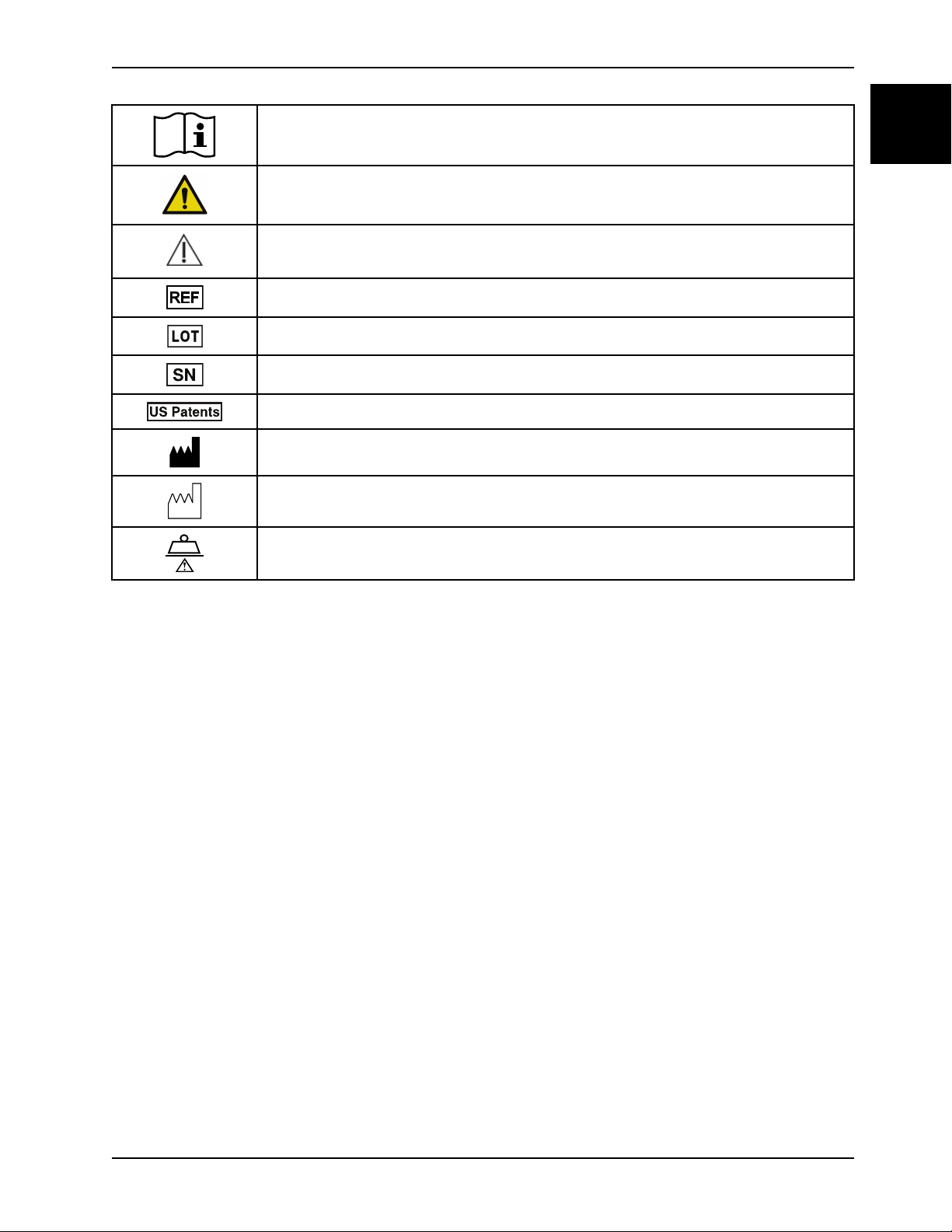
Symbols
Operating instructions/Consult instructions for use
General warning
Caution
Catalogue number
Lot (batch) code
Serial number
For US patents see www.stryker.com/patents
Manufacturer
Date of manufacturer
English
EN
Safe working load
www.stryker.com 6370-109-005 REV C
Page 6

sample text
Page 7

Table of Contents
Warning/Caution/Note Definition ............................................................................................................... 1-2
Summary of safety precautions................................................................................................................. 1-3
Introduction........................................................................................................................................... 1-4
Product description........................................................................................................................... 1-4
Indications for use ............................................................................................................................ 1-4
Expected service life......................................................................................................................... 1-4
Contraindications ............................................................................................................................. 1-4
Specifications.................................................................................................................................. 1-4
Product illustration............................................................................................................................ 1-5
Contact information .......................................................................................................................... 1-6
Serial number location ...................................................................................................................... 1-6
Date of manufacture......................................................................................................................... 1-6
Cot compatibility .............................................................................................................................. 1-6
Installation ............................................................................................................................................ 1-8
Installing the cot fastener................................................................................................................... 1-8
Selecting the vehicle safety hook ........................................................................................................ 1-8
Vehicle configuration ........................................................................................................................ 1-9
Positioning of the vehicle safety hook, front to back .............................................................................. 1-10
Positioning of the vehicle safety hook, side to side ................................................................................ 1-11
Installing the vehicle safety hook ....................................................................................................... 1-12
Installing the floor plate ................................................................................................................... 1-13
Installing the wall plate .................................................................................................................... 1-17
Installation checklist.............................................................................................................................. 1-22
Operation ........................................................................................................................................... 1-23
Mass casualty incident planning........................................................................................................ 1-23
Adjusting the rail assembly............................................................................................................... 1-23
Testing the cot fastener................................................................................................................... 1-25
Cleaning............................................................................................................................................. 1-26
Suggested cleaners........................................................................................................................ 1-26
Preventive maintenance ........................................................................................................................ 1-27
English
EN
www.stryker.com 6370-109-005 REV C 1-1
Page 8

Warning/Caution/Note Definition
English
EN
The words WARNING, CAUTION, and NOTE carry special meanings and should be carefully reviewed.
WARNING
Alerts the reader about a situation which, if not avoided, could result in death or serious injury. It may also describe
potential serious adverse reactions and safety hazards.
CAUTION
Alerts the reader of a potentially hazardous situation which, if not avoided, may result in minor or moderate injury to the
user or patient or damage to the product or other property. This includes special care necessary for the safe and
effective use of the device and the care necessary to avoid damage to a device that may occur as a result of use or
misuse.
Note: Provides special information to make maintenance easier or important instructions clearer.
1-2 6370-109-005 REV C www.stryker.com
Page 9

Summary of safety precautions
Always read and strictly follow the warnings and cautions listed on this page. Service only by qualified personnel.
WARNING
• Always replace the cot fastener if it has been involved in an accident.
• A height limit kit is recommended for vehicle deck heights less than 30 in. (67 cm).
• Install the cot fastener by qualified personnel only. Improper installation could result in injury to the patient or
operator.
• Always make sure that all cots meet the installation specifications for the Stryker cot fastener system.
• Failure to install the vehicle safety hook may cause injury to the patient or operator.
• Always make sure that the safety bar connects with the vehicle safety hook before you remove the cot from the
vehicle patient compartment to avoid the risk of injury.
• Do not allow the rail clamp to overlap the red adjustment limit label on the rail tube. To prevent the rail jaws from
releasing the cot frame, the space between the rail clamp and the rail stationary jaw must never exceed 1 in. (2.5
cm).
• Do not use hand or fingers to press the release button when the rail jaws are open. The rail clamp fastener closes
with a strong spring action.
• Always test the fastener using AMD Standard 004 as a minimum. Improper testing can result in injury.
• Always wipe the product with clean water and dry after cleaning. Some cleaning products are corrosive in nature
and may cause damage to the product. Failure to properly rinse and dry the product leaves a corrosive residue on
the surface of the product and may cause premature corrosion of critical components.
English
EN
CAUTION
• Improper usage of the product can cause injury to the patient or operator. Operate the product only as described in
this manual.
• Do not modify the product or any components of the product. Modifying the product can cause unpredictable
operation resulting in injury to patient or operator. Modifying the product also voids its warranty.
• Always set the cot load height to the proper stop height before operation.
• Always have a certified mechanic, familiar with ambulance vehicle construction, install the vehicle safety hook.
Consult the vehicle manufacturer before you install the vehicle safety hook. Make sure that the installation of the
vehicle safety hook does not damage or interfere with the brake lines, oxygen lines, fuel lines, fuel tank, or
electrical wiring of the vehicle.
• Do not use screws smaller than the 3/8 in. diameter specified to anchor the floor plates.
• Do not use a screw smaller than the 5/16 in. diameter specified to anchor the wall plate.
www.stryker.com 6370-109-005 REV C 1-3
Page 10

Introduction
English
EN
This manual assists you with the operation or maintenance of your Stryker product. Read this manual before operating
or maintaining this product. Set methods and procedures to educate and train your staff on the safe operation or
maintenance of this product.
CAUTION
• Improper usage of the product can cause injury to the patient or operator. Operate the product only as described in
this manual.
• Do not modify the product or any components of the product. Modifying the product can cause unpredictable
operation resulting in injury to patient or operator. Modifying the product also voids its warranty.
Notes
• This manual is a permanent part of the product and should remain with the product even if the product is sold.
• Stryker continually seeks advancements in product design and quality. This manual contains the most current
product information available at the time of printing. There may be minor discrepancies between your product and
this manual. If you have any questions, contact Stryker Customer Service or Technical Support at 1-800-327-0770.
Product description
The Stryker Ambulance Cot Fastener is designed to hold a compatible ambulance cot in an emergency vehicle for
patient transport purposes. The Ambulance Cot Fastener performs this function after the user manually loads the
compatible cot into the emergency vehicle and guides it into the fastener.
Indications for use
The Stryker Model 6370/6371/6377/6378/6391/6393 cot fasteners are not designed for any purpose other than to
restrict movement of an ambulance cot being transported in the patient compartment of an ambulance under normal
conditions.
Note: Usage of these products in any other way becomes the complete responsibility of the owner or user. The Model
6370/6371/6377/6378/6391/6393 cot fasteners comply to the Ambulance Manufacturers Division specification 004.
Caution must be used at all times during placement of the cot into the ambulance.
Expected service life
Cot fasteners have a seven year expected service life under normal use conditions and with appropriate periodic
maintenance.
Contraindications
None known.
Specifications
Model Type Part number
6371 Wall mounted 6371-000-000
6370 Floor mounted 6370-000-000
6377 Floor mounted 6377-000-000
1-4 6370-109-005 REV C www.stryker.com
Page 11

Introduction
A
B
C
D
Specifications (Continued)
Model Type Part number
6378 Floor mounted (reduced length) 6378-000-000
6391 Wall mounted mass casualty Power-
LOAD
6391 Floor mounted mass casualty Power-
LOAD
6393 Wall mounted mass casualty
Performance-LOAD
6393 Floor mounted mass casualty
Performance-LOAD
WARNING
• Always replace the cot fastener if it has been involved in an accident.
• A height limit kit is recommended for vehicle deck heights less than 30 in. (67 cm).
6391-001-001
6391-001-002
6393-001-001
6393-001-002
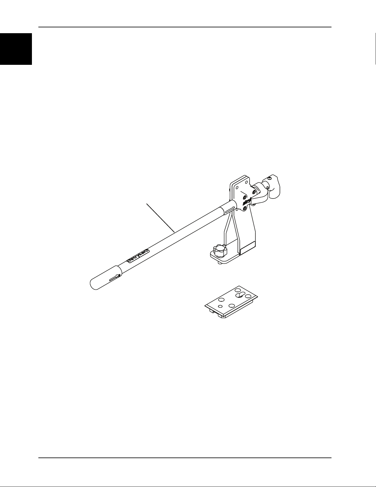
Product illustration
English
EN
Figure 1-1: Product illustration
A Rail assembly
B Floor plate
C
D Antler assembly
www.stryker.com 6370-109-005 REV C 1-5
Floor plates
Page 12
Introduction
A
English
EN
Contact information
Contact Stryker Customer Service or Technical Support at: 1-800-327-0770.
Stryker Medical
3800 E. Centre Avenue
Portage, MI 49002
USA
To view your operations or maintenance manual online, see https://techweb.stryker.com/.
Have the serial number (A) of your Stryker product available when calling Stryker Customer Service or Technical
Support. Include the serial number in all written communication.
Serial number location
Figure 1-2: Serial number location
Date of manufacture
The year of manufacture is the first 2 digits of the serial number.
Cot compatibility
The Stryker 6370/6371/6377/6378/6391/6393 cot fastener systems are compatible only with cots that conform to the
installation specifications.
1-6 6370-109-005 REV C www.stryker.com
Page 13

Introduction
Cot compatibility (Continued)
WARNING
• Install the cot fastener by qualified personnel only. Improper installation could result in injury to the patient or
operator.
• Always make sure that all cots meet the installation specifications for the Stryker cot fastener system.
Ambulance cots which currently meet these specifications are:
Stryker
• Model 6060 DX Emergency Transport
• Model 6070 LX Emergency Transport
• Model 6080 MX-PRO
• Model 6081 MX-PRO Incubator Transporter
• Model 6082 MX-PRO
• Model 6083 MX-PRO Bariatric Transport
• Model 6085 Performance-PRO XT
• Model 6086 Performance-PRO XT
• Model 6090 EZ-PRO
• Model 6091 EZ-PRO 2
• Model 6092 EZ-PRO R3
• Model 6092 EZ-PRO R4
• Model 6500 Power-PRO XT
• Model 6506 Power-PRO XT
• Model 6510 Power-PRO IT
• Model 6516 Power-PRO IT
English
EN
Ferno-Washington
• Model 29-M Three Level Roll-In Cot*
• Model 93 ES Squadmate™*
• Model 93 EX Squadmate™*
• Model 35-A Mobile Transporter™*
• Model 35-A+ Mobile Transporter Plus™*
• Model 35-IT Incubator Transporter*
• Model 93P PROFlexx®
• Model 35X PROFlexx®
• Model 28Z PROFlexx®
• PowerFlexx®
Notes
• Adjustment of the rail clamp assembly may be required in order to compensate for any variation in cot retaining
post position depending on the ambulance cot manufacturer and model number.
• * 1999 model year or earlier. Styker is not responsible for changes in specifications to other manufacturer’s cots.
www.stryker.com 6370-109-005 REV C 1-7
Page 14

Installation
English
EN
Installing the cot fastener
The Stryker cot fastener systems are compatible only with cots that conform to the installation specifications.
WARNING
• Install the cot fastener by qualified personnel only. Improper installation could result in injury to the patient or
operator.
• Always make sure that all cots meet the installation specifications for the Stryker cot fastener system.
Note: You may need to adjust the rail clamp assembly to compensate for any variation in the cot retaining post position
depending on the cot manufacturer and model number.
These instructions are intended for cots with antler style cot fastener systems. For crash-rated cot fasteners, see the
appropriate operations manual for installation instructions.
Selecting the vehicle safety hook
The vehicle safety hook is a device that ships with the cot. The cot safety bar and vehicle safety hook keep the cot from
being accidentally removed from the vehicle and provide increased operator assurance and confidence when loading
and unloading.
Note: These instructions are intended for cots with antler style cot fastener systems. For crash-rated cot fasteners, see
the appropriate operations manual for installation instructions. Crash-rated cot fasteners are shipped and installed with
their own vehicle safety hook, thus no additional hook is needed.
The vehicle safety hook was designed for compatibility and proper operation when loading and unloading the cot from a
vehicle that is compliant with Federal Regulation KKK-A-1822. Stryker offers three different types of vehicle safety
hooks that are ordered and shipped with your cot. These vehicle safety hook types meet the needs of various
emergency vehicle configurations, specifically the length and location of the floor structure support that is located in the
rear of the vehicle.
To select which vehicle safety hook is appropriate for your vehicle configuration:
• Consider the location of the floor structure support where there is adequate room to mount the vehicle safety hook.
• Mount the vehicle safety hook into the back of the vehicle. Provide bumper clearance to allow the operators to load
and unload the cot from the vehicle.
• Note the differences in vehicle design. Each vehicle safety hook provides a different mounting location option to
maintain the appropriate distance between the face of the vehicle safety hook and the edge of the door sill.
Due to the differences in vehicle dimensions and the floor structure support locations, each vehicle safety hook allows
for a different mounting location. Select the correct position for your vehicle safety hook installation.
• Positioning of the vehicle safety hook, front to back on page 1-10
• Positioning of the vehicle safety hook, side to side on page 1-11
Note: When you replace an existing vehicle safety hook with a new style, adjust the mounting location to maintain the
proper position of the vehicle safety hook face.
1-8 6370-109-005 REV C www.stryker.com
Page 15
Installation
Selecting the vehicle safety hook (Continued)
English
EN
Figure 1-3: Vehicle safety hook types
Vehicle configuration
CAUTION
• Always set the cot load height to the proper stop height before operation.
• Always have a certified mechanic, familiar with ambulance vehicle construction, install the vehicle safety hook.
Consult the vehicle manufacturer before you install the vehicle safety hook. Make sure that the installation of the
vehicle safety hook does not damage or interfere with the brake lines, oxygen lines, fuel lines, fuel tank, or
electrical wiring of the vehicle.
The cot is compatible with all vehicle deck heights that meet the Federal Specification for the Star-of-Life Ambulance
KKK-A-1822. See specifications for maximum load height.
According to Federal Specification for the Star-of-Life Ambulance KKK-A-1822:
• The rear of the ambulance shall be furnished with a sturdy, full-width, rear bumper, with step secured to the
vehicle’s chassis frame.
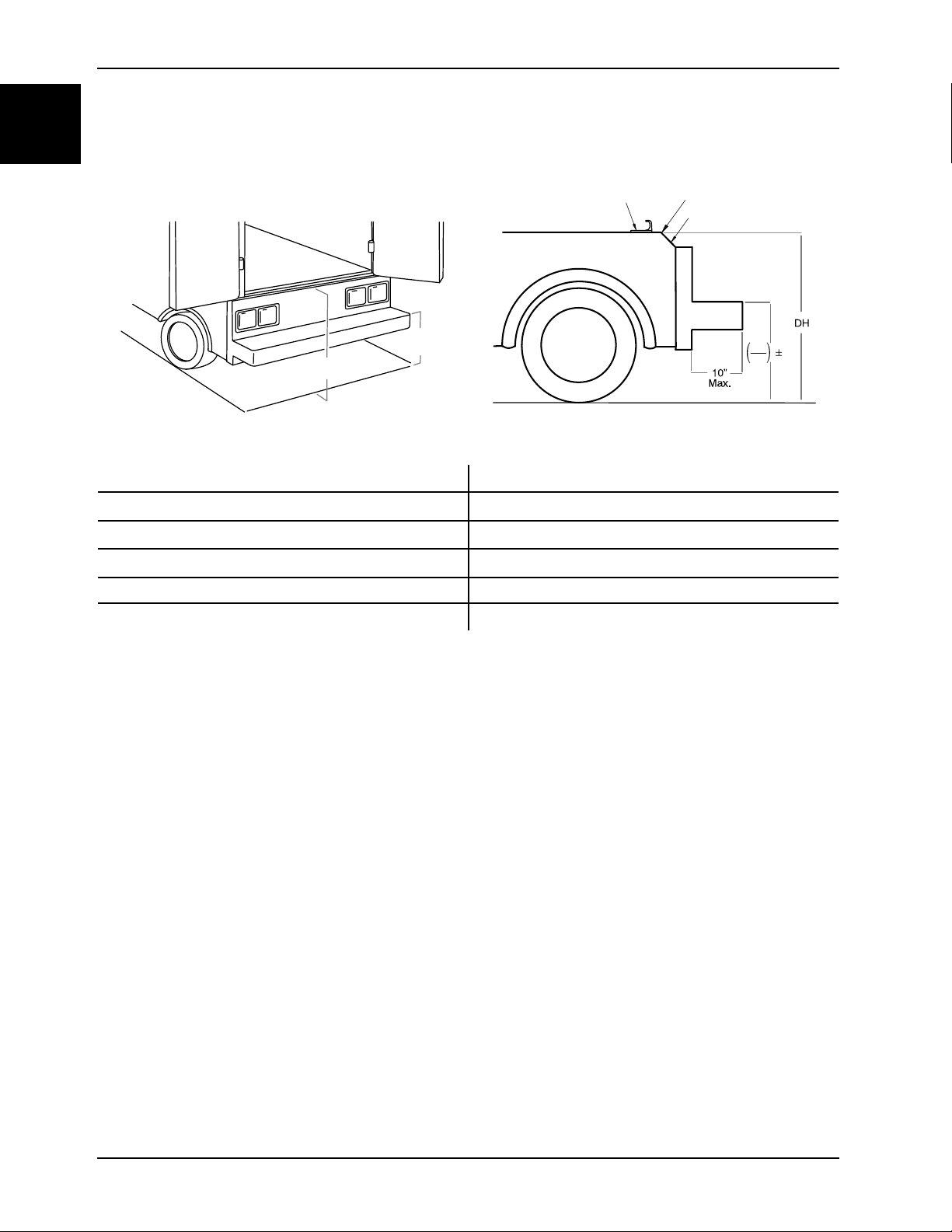
• The tread of the step shall have a minimum depth of 5 in. (13 cm) and a maximum depth of 10 in. (25 cm).
• If the step protrudes more than 7 in. (18 cm) from the rear of the vehicle, a fold-up step shall be furnished.
According to federal regulations (reference KKK-A-1822), the bumper height of the vehicle shall be installed equidistant
2 in. (± 5 cm) from the vehicle floor to the ground level, which is defined as the vehicle deck height. Installation of the
vehicle safety hook into any vehicle compliant with this federal specification provides adequate clearance for the cot
base to lower to its fully extended position.
www.stryker.com 6370-109-005 REV C 1-9
Page 16
Installation
DH
2
2
A
B
C D
E
F
A
B
English
EN
Vehicle configuration (Continued)
Figure 1-4: Deck and bumper height
A Deck height (DH)
B Bumper height
C Vehicle safety hook
D
Sill edge
E
F Bumper depth
Sill
Positioning of the vehicle safety hook, front to back
Check the front to back and side to side positioning when unloading and loading the cot to make sure that you install the
vehicle safety hook correctly.
To check the front to back positioning:
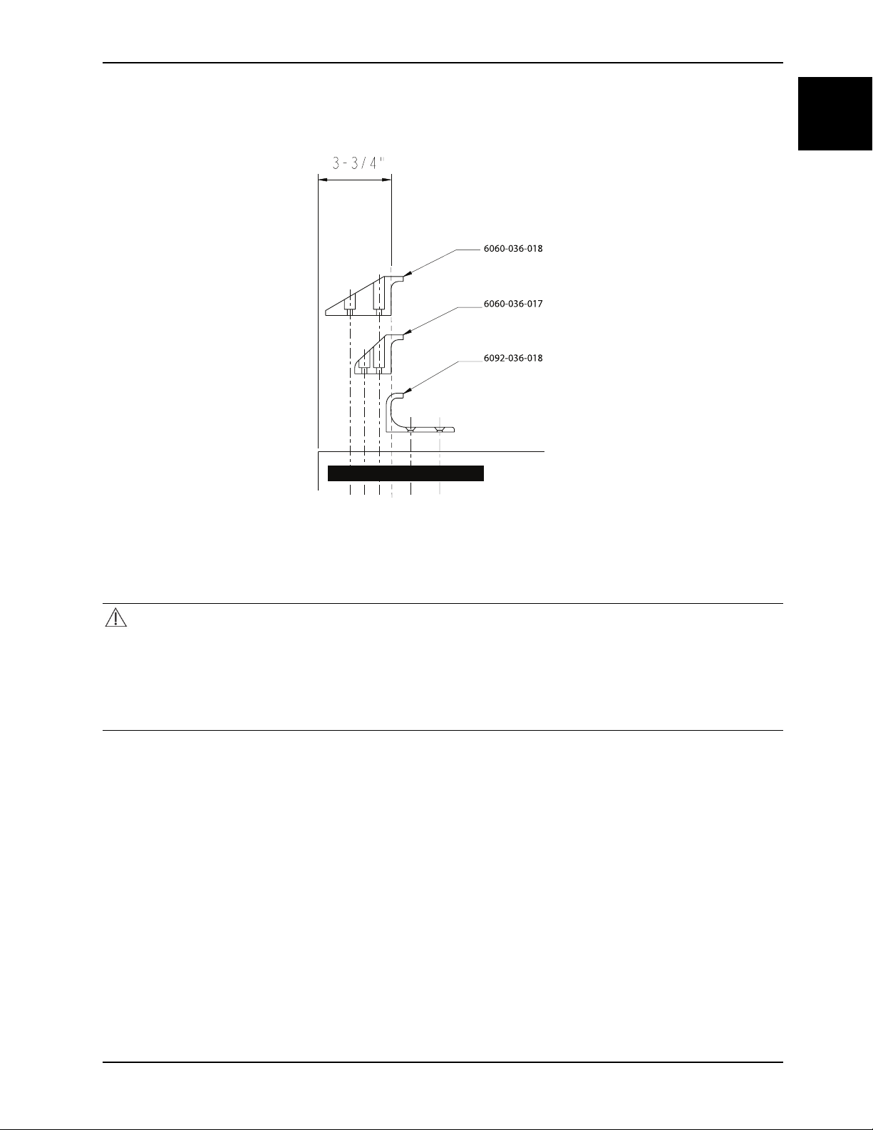
1. Select the appropriate vehicle safety hook (Selecting the vehicle safety hook on page 1-8).
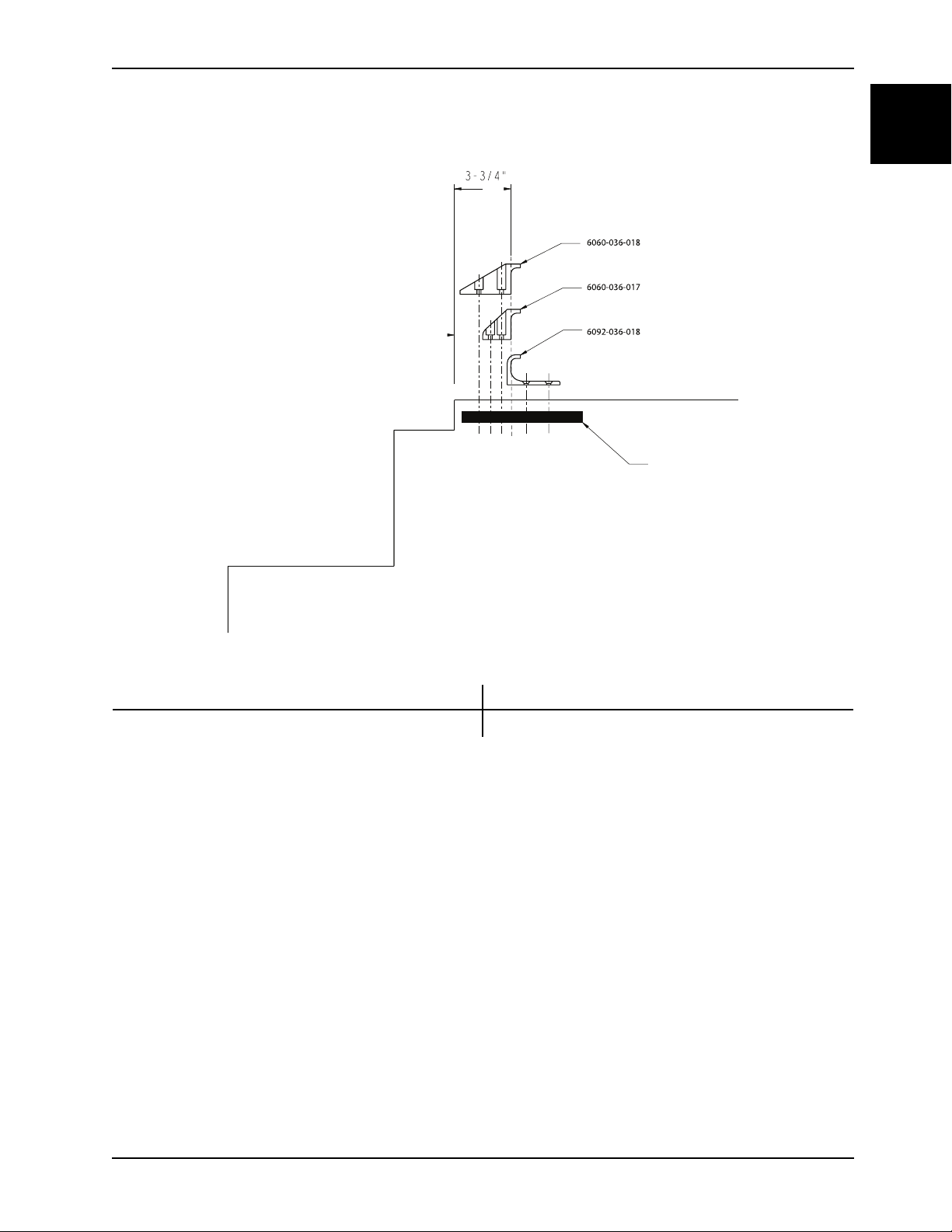
2. Position the vehicle safety hook at least 3-3/4 in. from the leading edge of the door sill (A). The recommended
distance from the face of the safety hook to be no less than 3-3/4 in.
3. Make sure that you can secure the vehicle safety hook to the mount in the back of the vehicle.
4. Make sure that you have adequate bumper clearance to allow the cot to be loaded and unloaded from the vehicle.
5. Confirm the side to side placement of the vehicle safety hook (Positioning of the vehicle safety hook, side to side on
page 1-11).
1-10 6370-109-005 REV C www.stryker.com
Page 17
Installation
A
B
Positioning of the vehicle safety hook, front to back (Continued)
English
EN
Figure 1-5: Vehicle safety hook placement
A
B Floor structure support
Sill
Positioning of the vehicle safety hook, side to side
Before you install the vehicle safety hook, check the front to back and side to side positioning, when you unload and
load the cot.
To check the side to side positioning:
1. Remove the cot from the cot fastener and unload it from the vehicle.
2. Note the position of the cot load wheels and the cot safety bar when you are remove the cot.
3. Mark the center of the cot safety bar on the vehicle floor.
4. Make sure that the position marked in step 3 is where the cot safety bar connects with the vehicle safety hook every
time when you unload the cot in a variety of positions (such as all the way to the left and all the way to the right).
www.stryker.com 6370-109-005 REV C 1-11
Page 18

Installation
English
EN
Positioning of the vehicle safety hook, side to side (Continued)
Notes
• If the cot safety bar does not connect with the vehicle safety hook in any of these positions (left, center, or
right), modify the vehicle. Do not modify the cot or the vehicle safety hook.
• If the cot safety bar connects with vehicle safety hook every time, install the vehicle safety hook.
Installing the vehicle safety hook
Before installing the vehicle safety hook, the certified mechanic should plan for the placement of the vehicle safety
hook in the rear of the vehicle patient compartment.
WARNING
• Failure to install the vehicle safety hook may cause injury to the patient or operator.
• Always have a certified mechanic, familiar with ambulance vehicle construction, install the safety hook.
• Always make sure that the safety bar connects with the vehicle safety hook before you remove the cot from the
vehicle patient compartment to avoid the risk of injury.
Hardware required (not supplied):
• (2) Grade 5, minimum 1/4”-20 socket head cap screws * for the short vehicle safety hook or long vehicle safety
hook
• (2) Grade 5, minimum 1/4”-20 flat socket head cap screws * for the J vehicle safety hook
• (2) Flat washers
• (2) Lock washers
• (2) 1/4”-20 nuts
Note: The length of the socket head cap screws depend on the thickness of the vehicle floor. Use screws that are long
enough to go completely through the vehicle patient compartment floor, washer, and nut, with at least two full threads in
the nut.
1. Determine the correct vehicle safety hook front to back and side to side positioning, so the cot safety bar connects
to the vehicle safety hook every time.
• Positioning of the vehicle safety hook, front to back on page 1-10
• Positioning of the vehicle safety hook, side to side on page 1-11
2. Drill the holes for the screws.
3. Fasten the vehicle safety hook to the vehicle patient compartment floor.
4. Make sure that the cot safety bar connects with the vehicle safety hook before you remove the cot from the vehicle
patient compartment.
1-12 6370-109-005 REV C www.stryker.com
Page 19
Installation
A
B
C
DE
Installing the vehicle safety hook (Continued)
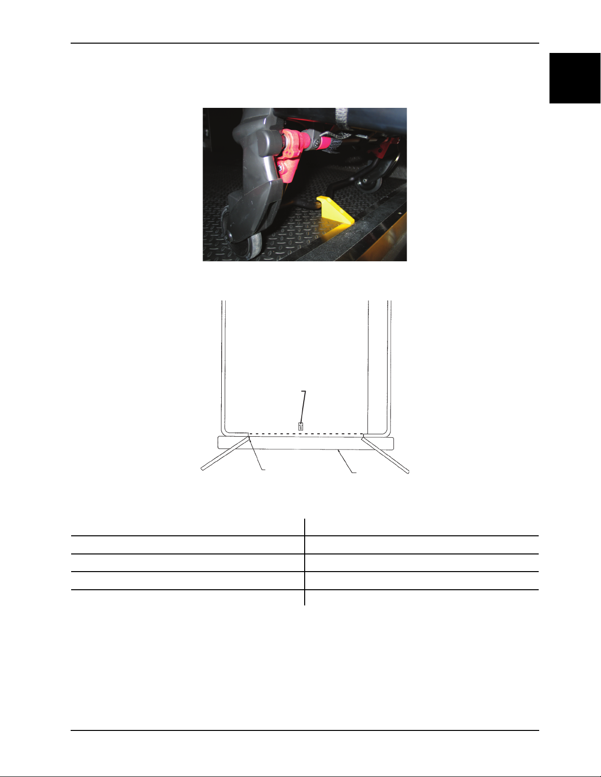
Figure 1-6: Safety bar secured in the vehicle safety hook
English
EN
Figure 1-7: Vehicle safety hook placement
A
B
C Squad bench
D Bumper
E
After installation, make sure that the cot legs lock into the load position without contacting the vehicle bumper.
Installing the floor plate
The Stryker cot fastener system for the floor plate mounting model is compatible only with cots that conform to the floor
plate mounting installation specifications.
www.stryker.com 6370-109-005 REV C 1-13
Top view of vehicle
Vehicle safety hook
Door frame
Page 20
Installation
12-5/8” (32 cm)
24.000
(Ref.)
(61 cm)
6-1/8”
(15,6
cm)
14-15/16”
(37,9 cm)
37-5/8”
(95,6 cm)
80.000 (Ref.)
(203 cm)
2-5/8”
(6,6 cm)
14-5/8” (Ref.)
(37,1 cm)
A
B
C
D
E
F
G
English
EN
Installing the floor plate (Continued)
To position the antler floor mounting plates:
1. Determine the desired position of the cot inside the vehicle to allow for proper clearance around the cot.
Note: Federal ambulance specifications regarding aisle width and attendant seating may affect positioning of the
mounting brackets. If specifications do not apply, the installer should be certain that there is adequate clearance for
proper patient access, traction splint projection, rear door closure, and so on.
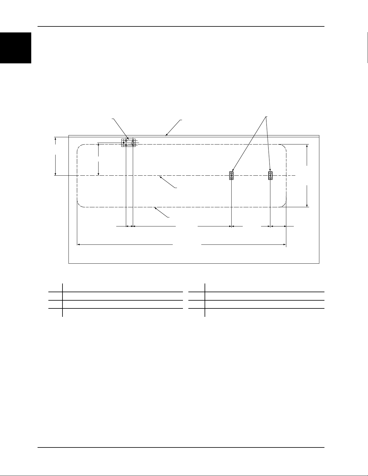
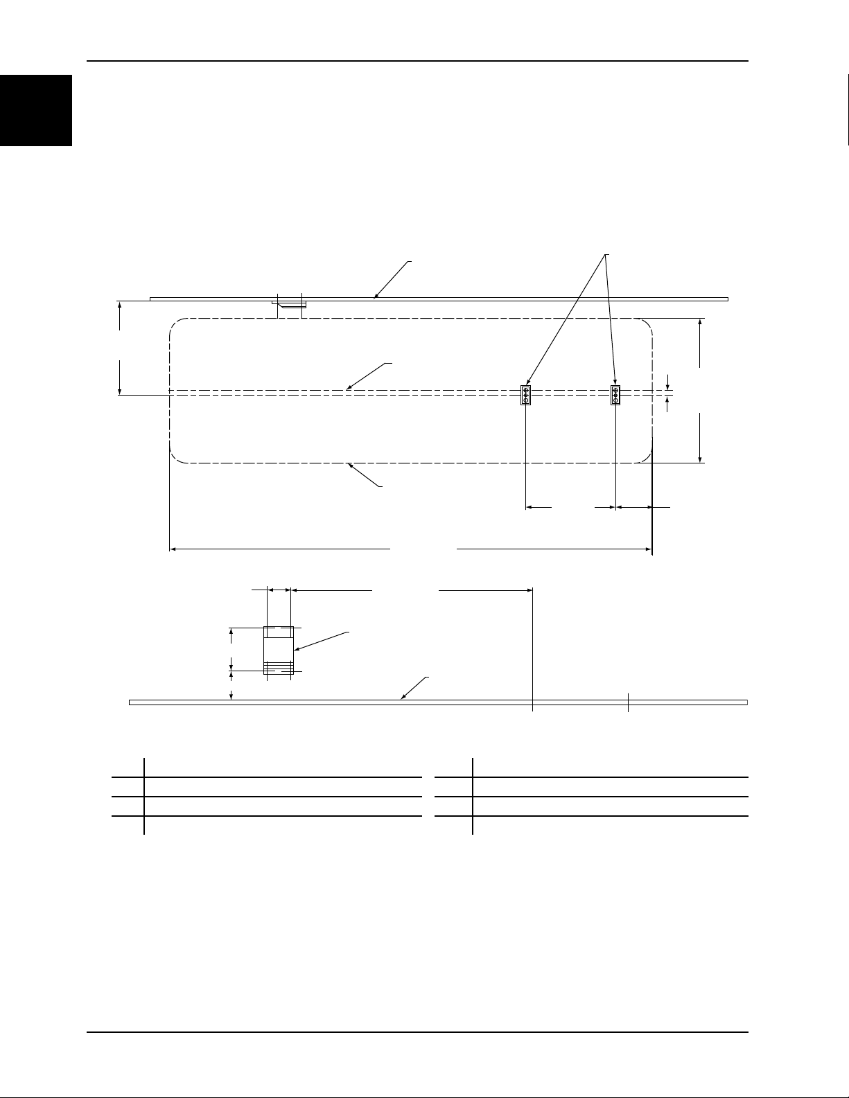
2. Using the dimensions shown in Figure 1-8 on page 1-14, locate and drill the points where the floor plates will attach.
Figure 1-8: Floor plate installation locations
Rail support bracket floor plate
A
B Wall of vehicle F
Antler floor plates
C
E Cot center line
Cot perimeter
G Cot head end
D Rear of ambulance
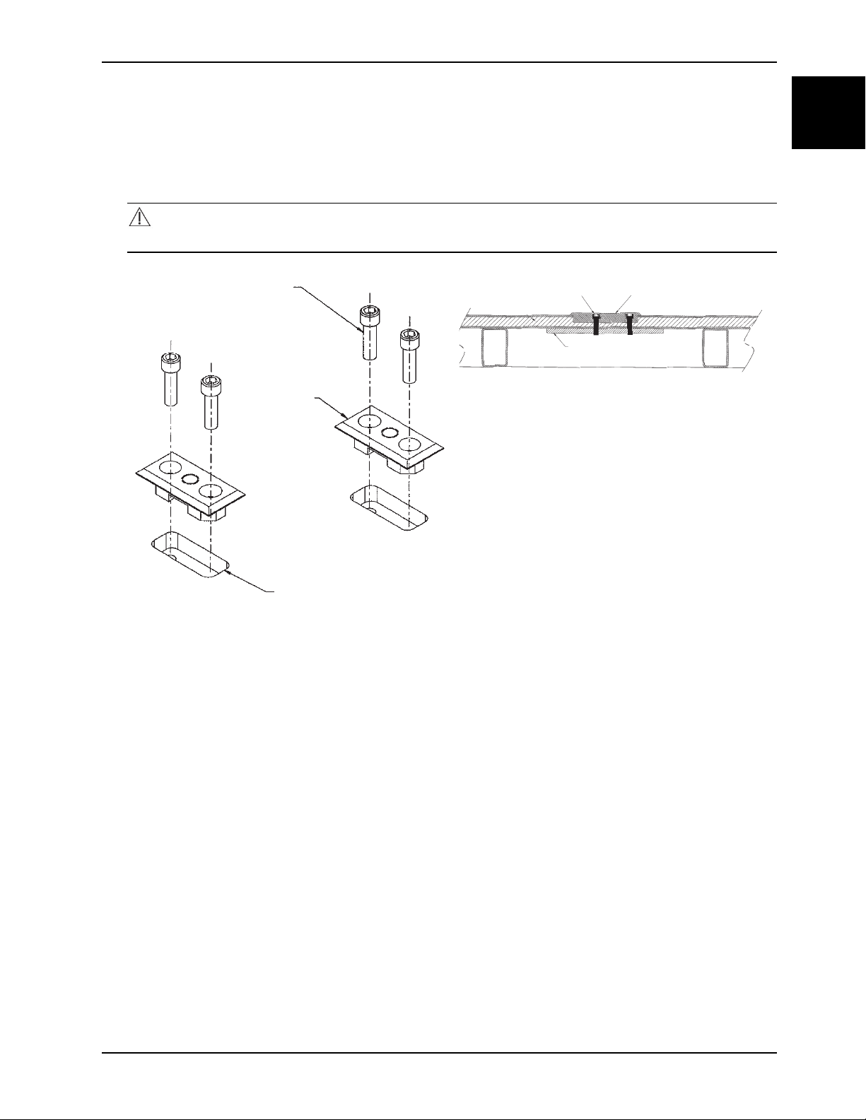
3. Cut 1 in. x 2-1/2 in. x 9/16 in. deep recessed openings (A) into the floor centered over the locating holes (Figure 1-9
on page 1-15).
1-14 6370-109-005 REV C www.stryker.com
Page 21
Installation
A
B
C
B
C
D
Installing the floor plate (Continued)
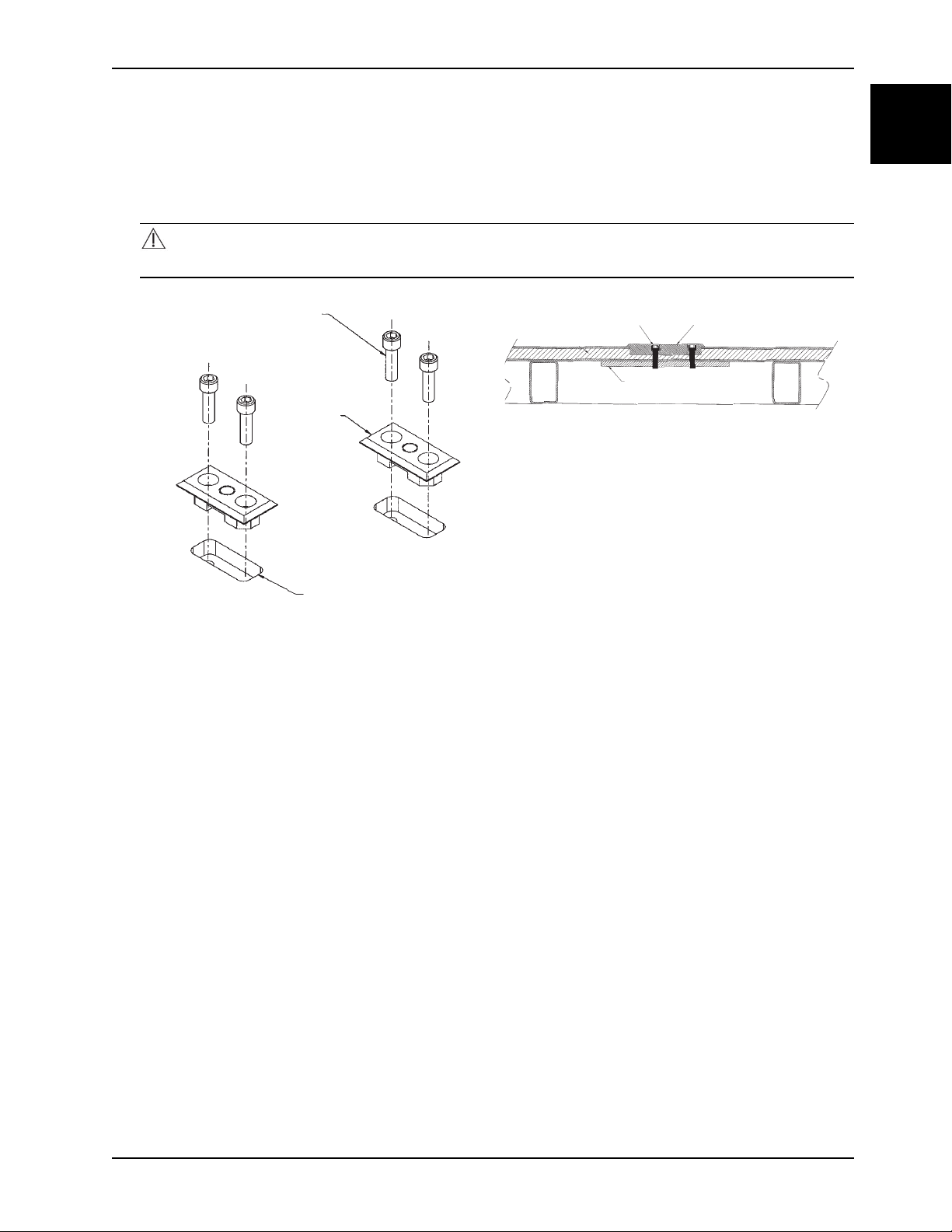
4. Using two 3/8 in. diameter socket head cap screws (B), preferably grade 8, anchor each floor plate (C) into the
recessed openings with the counter-bored holes facing up (Figure 1-10 on page 1-15).
Note: Steel backing plates (or equivalent) (D) (not supplied) are required for added support (Figure 1-10 on page 1-
15).
CAUTION
Do not use screws smaller than the 3/8 in. diameter specified to anchor the floor plates.
Figure 1-10: Anchor floor plate into recessed
openings
English
EN
Figure 1-9: Cut recessed openings over locating
holes
5. Using the dimensions shown in Figure 1-8 on page 1-14, locate and drill the four points where the rail support
bracket floor plate will attach. Cut one 2 1/2 in. x 5 in. x 9/16 in. deep opening (E) into the floor centered over the
locating points (Figure 1-11 on page 1-16).
www.stryker.com 6370-109-005 REV C 1-15
Page 22
Installation
E
F
G
A
B
B
English
EN
Installing the floor plate (Continued)
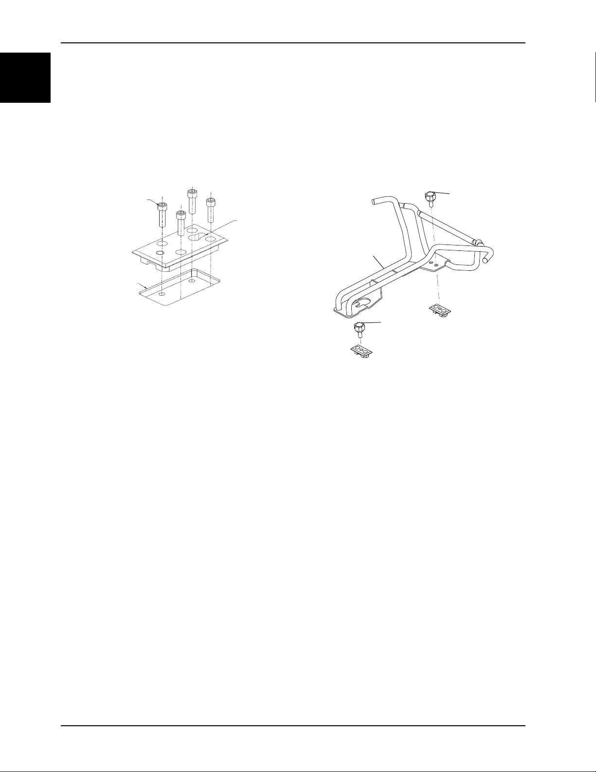
6. Using four 3/8 in. diameter socket head cap screws (F), anchor the floor plate into the recessed opening with the
counter-bored holes facing up (G) (Figure 1-11 on page 1-16). The keyhole should face toward the front of the
vehicle.
• A steel backing plate (or equivalent) is required for added support (not supplied).
• One set of additional floor plates is supplied with the Model 6377 fastener to allow alternate positioning
anywhere on the patient compartment floor. Cot space requirements are the same as shown in Figure 1-8 on
page 1-14. Repeat the above procedure to install the alternate position floor plates.
Figure 1-11: Floor plate anchor and locating points
Figure 1-12: Position and fasten antler over the floor
plates
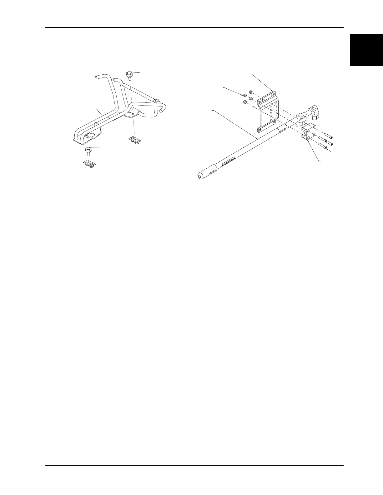
7. Position the antler over the floor plates and fasten the antler (A) with the red knobs (B) (Figure 1-12 on page 1-16).
Notes
• Use the additional mounting holes in the antler bracket to position the antler for the Model 6371 wall mounted
cot fastener system.
• The red knobs that fasten the antler assembly to the patient compartment floor plate are not compatible with
the universal floor plate. See the Universal Floor Plate Installation Instructions for floor plate installation.
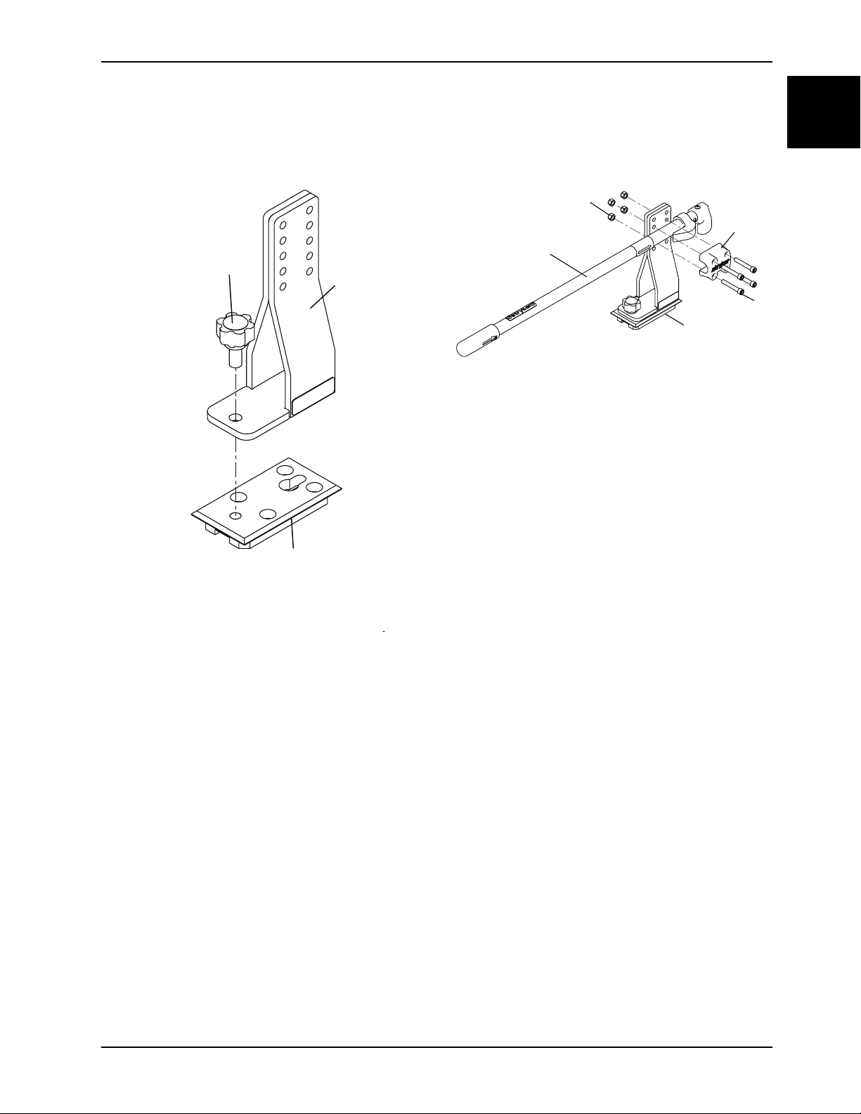
8. Position the rail support bracket (C) over the floor mounting plate (D) (Figure 1-13 on page 1-17).
9. Insert the socket head screw into the keyhole and slide the assembly forward until the hole in the bracket lines up
with the tapped hole in the floor plate.
10. Fasten securely by tightening one of the red knobs (E) (Figure 1-13 on page 1-17).
11. Position the rail assembly (F) on the support bracket (G) (Figure 1-14 on page 1-17).
1-16 6370-109-005 REV C www.stryker.com
Page 23
Installation
C
D
E
F
G
H
K
J
Installing the floor plate (Continued)
12. Install the four Nylock hex nuts (H) and four 5/16−18 x 2 in. socket head cap screws (J) to attach the rail clamp (K)
to the rail assembly (Figure 1-14 on page 1-17).
Figure 1-14: Attach rail clamp to rail assembly
English
EN
Figure 1-13: Fasten the rail support bracket
Installing the wall plate
The Stryker cot fastener system for the wall plate mounting model is compatible only with cots which conform to the wall
plate mounting installation specifications.
To position the antler floor mounting plates:
1. Determine the desired position of the cot inside the vehicle to allow for proper clearance around the cot.
Note: Federal ambulance specifications regarding that aisle width and attendant seating may affect positioning of
the mounting brackets. If specifications do not apply, the installer should be certain that there is adequate
clearance for proper patient access, traction splint projection, rear door closure, etc.
www.stryker.com 6370-109-005 REV C 1-17
Page 24
Installation
24.000
(Ref.)
(61 cm)
6-1/8”
(15,6
cm)
14-15/16”
(37,9 cm)
80.000 (Ref.)
(203 cm)
2-5/8”
(6,6 cm)
14-5/8”
(37,1 cm)
1-1/8”
(2,9 cm)
3-5/8””
(9,2 cm)
37-3/8”
(94,9 cm)
6-1/2” (16,5 cm)
4-5/16” (10,9 cm)
A
B
C
D
E
F
G
H
English
EN
Installing the wall plate (Continued)
2. Using the dimensions shown in (Figure 1-15 on page 1-18), locate and drill the points where the floor plates will
attach.
Note: When installing the wall plate for the Stryker Model 6371 cot fastener with the long rail assembly option
(6362-021-000), measure 33 in. for the horizontal dimension and 4 1/16 in. for the vertical dimension. The Stryker
Model 6371 cot fastener with the long rail assembly option is only compatible with the extended head section
assembly (9996-390-200).
Figure 1-15: Wall plate installation locations
A Wall of vehicle E
Antler floor plates
B
C Rear of ambulance G
Cot perimeter
F Cot head end
Wall mounting bracket
D Cot center line H Floor of vehicle
3. Cut two 1 in. x 2-1/2 in. x 9/16 in. deep recessed openings (A) into the floor centered over the locating holes
(Figure 1-16 on page 1-19).
1-18 6370-109-005 REV C www.stryker.com
Page 25
Installation
A
B
C
B
C
D
Installing the wall plate (Continued)
4. Using two 3/8 in. diameter socket head cap screws (B) (not supplied), preferably grade 8, anchor each floor plate
(C) into the recessed openings with the counter-bored holes facing up (Figure 1-17 on page 1-19).
Note: A steel backing plate (or equivalent) (D) (not supplied) is required for added support (Figure 1-17 on page 1-
19).
CAUTION
Do not use screws smaller than the 3/8 in. diameter specified to anchor the floor plates.
Figure 1-17: Anchor wall plate into recessed
openings
English
EN
Figure 1-16: Cut recessed openings over locating
holes
5. Using the dimensions shown in Figure 1-15 on page 1-18, locate and drill the four points where the rail wall
mounting bracket will attach.
www.stryker.com 6370-109-005 REV C 1-19
Page 26
Installation
E
F
G
J
H
F
E
English
EN
Installing the wall plate (Continued)
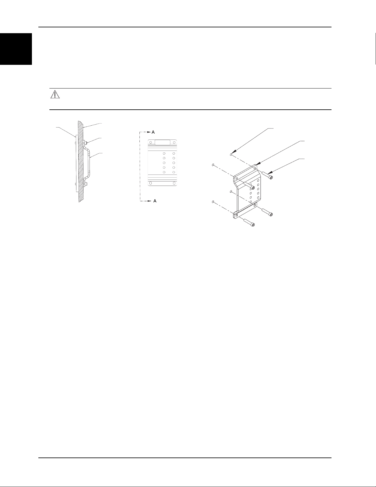
6. Using four 5/16 in. diameter socket head cap screws (E) (not supplied), anchor the wall bracket (F) through the 11/
32 in. diameter holes (G) to the wall (H) (Figure 1-18 on page 1-20)(Figure 1-19 on page 1-20).
Note: A steel backing plate (or equivalent) (J) (not supplied) is required for added support (Figure 1-18 on page 1-
20).
CAUTION
Do not use a screw smaller than the 5/16 in. diameter specified to anchor the wall plate.
Figure 1-18: Wall plate bracket and steel backing
Figure 1-19: Wall plate bracket and locating points
7. Position the antler over the floor plates and fasten the antler (A) with the red knobs (B) (Figure 1-20 on page 1-21).
Notes
• Use the additional mounting holes in the antler bracket to position the antler for the Model 6370/6377/6378
floor mounted cot fastener systems.
• The red knobs that fasten the antler assembly to the patient compartment floor plate are not compatible with
the universal floor plate. See the Universal Floor Plate Installation Instructions for floor plate installation.
8. Position the rail assembly (C) on the wall mounting bracket (D) (Figure 1-21 on page 1-21).
9. Install the four Nylock hex nuts (E) and four 5/16−18 x 2 in. socket head cap screws (F) to attach the rail clamp (G)
to the rail assembly (Figure 1-21 on page 1-21).
1-20 6370-109-005 REV C www.stryker.com
Page 27
Installation
A
B
B
C
D
E
F
G
Installing the wall plate (Continued)
Figure 1-20: Position and fasten antler over the floor
plates
English
EN
Figure 1-21: Attach the rail clamp to rail assembly
www.stryker.com 6370-109-005 REV C 1-21
Page 28

Installation checklist
English
EN
Follow this checklist with a Stryker Ambulance Cot Fastener Model 6370/6371/6377/6378/6391/6393 compatible cot.
Make sure that you do not have any unused components after installation. Your Stryker Ambulance Cot
Fastener does not ship with any extra components. If you have any unused components after installation, call
Stryker service.
Visually check that all bolts and screws are tightened with no signs of protruding or missing fasteners.
Lift the vehicle bumper to the raised position, if equipped.
Load the compatible cot into the cot fastener (see Cot compatibility on page 1-6).
Make sure that the cot is locked into the cot fastener by pulling in and out and side to side on the foot end of the
cot.
Pull to remove the cot from the vehicle patient compartment. Make sure that the cot safety bar connects with
the vehicle safety hook before you remove the cot from the vehicle patient compartment.
Test the fastener for proper operation (see Testing the cot fastener on page 1-25).
Product serial number:
Installed by: Date:
Inspected by: Date:
Note: Maintain a copy of this record for at least seven years.
1-22 6370-109-005 REV C www.stryker.com
Page 29
Operation
Mass casualty incident planning
You must use the Power-LOAD system, 6370 antler assembly (6370-230-038), or 6378 antler assembly (6378-030-038)
for mass casualty incidents.
WARNING
• Do not allow the rail clamp to overlap the red adjustment limit label on the rail tube. To prevent the rail jaws from
releasing the cot frame, the space between the rail clamp and the rail stationary jaw must never exceed 1 in. (2.5
cm).
• Do not use hand or fingers to press the release button when the rail jaws are open. The rail clamp fastener closes
with a strong spring action.
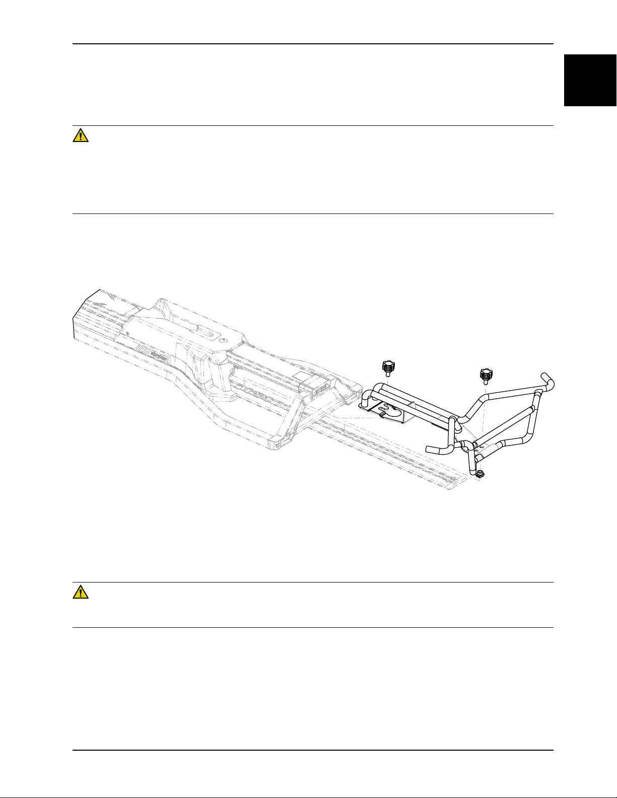
The mass casualty cot fasteners include a rail assembly for wall or floor mount. You should store this rail assembly in a
cabinet in case of emergency for quick attachment in the vehicle patient compartment.
See Figure 1-22 on page 1-23.
English
EN
Figure 1-22: Performance-LOAD installation
Adjusting the rail assembly
Adjustment of the rail assembly may be required to compensate for slight variation in the position of the cot post.
WARNING
Do not allow the rail clamp to overlap the red adjustment limit label on the rail tube. To prevent the rail jaws from
releasing the cot frame, the space between the rail clamp and the rail stationary jaw must never exceed 1 in. (2.5 cm).
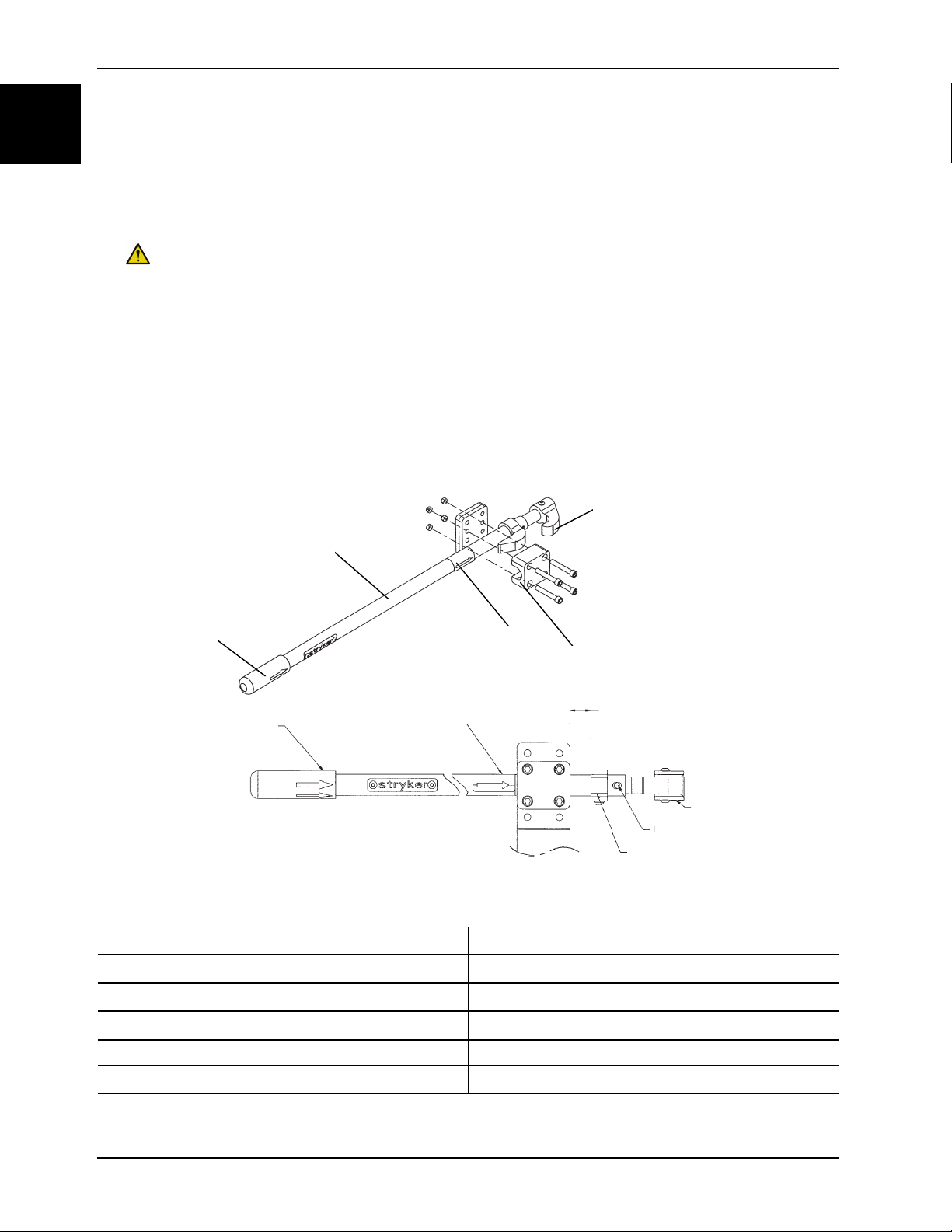
To vertically adjust the rail assembly (Figure 1-23 on page 1-24):
1. Remove the rail clamp (A) and rail assembly (B) from the existing mounting holes.
2. Move the rail clamp and rail assembly to the set of holes that align the clamp jaws (C) with the cot post.
3. Position the rail assembly front to back. Adjustment is limited to 1/2 in. front to back or 1 in. total movement.
Note: Do not overlap the adjustment limit label (D) on the rail assembly.
4. When adjustment is complete, rotate the rail assembly so the jaws are parallel with the floor.
www.stryker.com 6370-109-005 REV C 1-23
Page 30
Operation
A
B
D
E
C
Adjustment Limit Lab
el
A
B
C
D
E
D
E
F
G
H
I
English
EN
Adjusting the rail assembly (Continued)
5. Tighten the mounting screws until the rail clamp is drawn firmly against the support bracket.
6. Push the rail handle (E) forward until the release button engages and the jaws lock in the open position.
7. Guide the cot into the fastener at a slight angle by connecting the loading wheels with the antler one at a time
(Figure 1-24 on page 1-25).
WARNING
Do not use hand or fingers to press the release button when the rail jaws are open. The rail clamp fastener closes
with a strong spring action.
8. Move the foot end of the cot sideways until the cot post enters the rail jaws and presses the release button. The rail
jaws will close, locking the cot securely in position.
Note: Cot bedding may prevent attendants from seeing the rail jaws close around the cot post. Make sure that the
cot is locked into the fastener by firmly pulling side to side on the foot end of the cot.
9. Use one hand to push the rail handle forward far enough for the jaws to release the cot post. With the other hand,
grasp the cot and roll it away from the rail.
A Rail clamp
B Rail assembly
C Clamp jaws
D Adjustment limit label
E Rail handle
F 1” maximum adjustment
1-24 6370-109-005 REV C www.stryker.com
Figure 1-23: Adjusting the rail assembly
Page 31

Operation
Adjusting the rail assembly (Continued)
G
H Moveable jaw
I
Release button
Stationary jaw
English
EN
Figure 1-24: Guiding the cot into the fastener
Testing the cot fastener
WARNING
Always test the fastener using AMD Standard 004 as a minimum. Improper testing can result in injury.
To test the fastener:
1. Guide the cot into the cot fastener.
2. Make sure that the antler connects with the head end loading wheels of the cot.
3. Make sure that the rail clamp jaws are secure to the center of the cot post.
4. Test the fastener using AMD Standard 004 as a minimum.
Note: The fastener may be put into service after successfully passing steps two and three.
www.stryker.com 6370-109-005 REV C 1-25
Page 32

Cleaning
English
EN
Suggested cleaners
In general, when used in concentrations recommended by the manufacturer, either phenolic type or quaternary
(excluding Virex® TB) type disinfectants can be used. Iodophor type disinfectants are not recommended for use
because staining may occur.
WARNING
Always wipe the product with clean water and dry after cleaning. Some cleaning products are corrosive in nature and
may cause damage to the product. Failure to properly rinse and dry the product leaves a corrosive residue on the
surface of the product and may cause premature corrosion of critical components.
Suggested cleaners include:
• Quaternary cleaners (active ingredient - ammonium chloride)
• Phenolic cleaners (active ingredient - o-phenylphenol)
• Chlorinated bleach solution (5.25% - less than 1 part bleach to 100 parts water)
Avoid over saturation. Do not allow the product to stay wet longer than the chemical manufacturer's guidelines for
proper disinfecting.
Note: Failure to follow the above directions when using these types of cleaners may void this product’s warranty.
1-26 6370-109-005 REV C www.stryker.com
Page 33

Preventive maintenance
The following schedule is a general guide to maintenance. Factors such as weather, terrain, geographical location, and
individual usage will alter the required maintenance schedule. If you are unsure how to perform these checks, contact
your Stryker Service Technician. If you are in doubt as to what intervals to follow in maintaining your product, consult
your Stryker Service Technician. Check each routine and replace worn parts if necessary.
Routine Every
1 month 3 months 6 months 12 months
Cot and cot fastener
fit and function
All fasteners are
secure
X
X
English
EN
www.stryker.com 6370-109-005 REV C 1-27
Page 34

sample text
Page 35

Sujeción de camilla para ambulancias
6393 6370
6371
6377
6378
6391
Manual de uso
2018/06 C.0 6370-109-005 REV C
www.stryker.com
Page 36

sample text
Page 37

Símbolos
Instrucciones de utilización/consultar las instrucciones de uso.
Advertencias generales.
Precaución.
Número de catálogo.
Código de lote.
Número de serie.
Para patentes estadounidenses, visite www.stryker.com/patents.
Fabricante.
Fecha de fabricación
Español
ES
Carga de trabajo segura
www.stryker.com 6370-109-005 REV C
Page 38

sample text
Page 39

Índice
Definición de advertencia, precaución y nota ............................................................................................... 2-2
Resumen de las precauciones de seguridad................................................................................................2-3
Introducción ..........................................................................................................................................2-4
Descripción del producto ................................................................................................................... 2-4
Indicaciones de uso .......................................................................................................................... 2-4
Vida útil prevista ..............................................................................................................................2-4
Contraindicaciones........................................................................................................................... 2-4
Especificaciones.............................................................................................................................. 2-5
Ilustración del producto .....................................................................................................................2-5
Información de contacto .................................................................................................................... 2-6
Ubicación del número de serie............................................................................................................ 2-6
Fecha de fabricación ........................................................................................................................ 2-6
Compatibilidad de camillas................................................................................................................. 2-7
Instalación ............................................................................................................................................2-8
Instalación de la sujeción de camilla .................................................................................................... 2-8
Selección del gancho de seguridad del vehículo..................................................................................... 2-8
Configuración del vehículo................................................................................................................. 2-9
Colocación del gancho de seguridad del vehículo de la parte frontal a la posterior...................................... 2-10
Colocación del gancho de seguridad del vehículo de lado a lado ............................................................. 2-11
Instalación del gancho de seguridad del vehículo.................................................................................. 2-12
Instalación de la placa de suelo ........................................................................................................ 2-13
Instalación de la placa de pared........................................................................................................ 2-17
Lista de comprobación de la instalación.................................................................................................... 2-22
Uso ................................................................................................................................................... 2-23
Planificación de incidentes con múltiples víctimas................................................................................. 2-23
Ajuste del conjunto del raíl ............................................................................................................... 2-23
Prueba de la sujeción de camilla....................................................................................................... 2-25
Limpieza............................................................................................................................................. 2-26
Productos de limpieza propuestos ..................................................................................................... 2-26
Mantenimiento preventivo ...................................................................................................................... 2-27
Español
ES
www.stryker.com 6370-109-005 REV C 2-1
Page 40

Español
ES
Definición de advertencia, precaución y nota
Las palabras ADVERTENCIA, PRECAUCIÓN y NOTA tienen un significado especial y deberán revisarse detenidamente.
ADVERTENCIA
Advierte al lector sobre situaciones que, si no se evitan, podrían producir la muerte o lesiones graves. También puede
describir posibles reacciones adversas graves y peligros para la seguridad.
PRECAUCIÓN
Advierte al lector sobre situaciones potencialmente peligrosas que, si no se evitan, pueden producir lesiones leves o
moderadas al usuario o a la paciente, o daños al producto u otras propiedades. Incluye cuidados especiales necesarios
para el uso seguro y eficaz del dispositivo, y para evitar dañarlo con el uso o el mal uso.
Nota: Ofrece información especial que facilita el mantenimiento o aclara instrucciones importantes.
2-2 6370-109-005 REV C www.stryker.com
Page 41

Resumen de las precauciones de seguridad
Lea siempre las advertencias y precauciones indicadas en esta página y sígalas escrupulosamente. Las reparaciones
solo puede realizarlas personal cualificado.
ADVERTENCIA
• Sustituya siempre la sujeción de camilla si se ha utilizado en un accidente.
• Se recomienda un kit de límite de altura para las alturas de plataforma del vehículo de menos de 67 cm.
• La sujeción de camilla solo debe instalarla personal cualificado. Una instalación inadecuada puede provocar
lesiones al paciente o al operador.
• Asegúrese siempre de que todas las camillas cumplan las especificaciones de instalación del sistema de sujeción
de camilla de Stryker.
• No permita que la abrazadera de raíl se superponga a la etiqueta roja del límite de ajuste del tubo del raíl. Para
evitar que las mordazas del raíl liberen el bastidor de la camilla, el espacio situado entre la abrazadera de raíl y la
mordaza fija de este nunca podrá ser superior a 2,5 cm.
• No utilice las manos ni los dedos para pulsar el botón de liberación cuando las mordazas del raíl estén abiertas. La
sujeción de la abrazadera de raíl se cierra con un fuerte efecto de resorte.
• Pruebe siempre la sujeción usando el estándar AMD 004 como mínimo. Una prueba incorrecta puede derivar
lesiones.
• Limpie siempre el producto con agua limpia y séquelo después. Algunos productos de limpieza son corrosivos por
naturaleza y pueden provocar daños al producto. Si no se aclara y seca debidamente, en la superficie del producto
quedará un residuo corrosivo que podría provocar la corrosión prematura de componentes esenciales.
Español
ES
PRECAUCIÓN
• El uso inadecuado del producto puede provocar lesiones al paciente o al operador. Utilice el producto únicamente
como se describe en este manual.
• No modifique el producto ni ninguno de sus componentes. La modificación del producto puede provocar un
funcionamiento impredecible que a su vez cause lesiones al paciente o al operador. La modificación del producto
también anula su garantía.
• Disponga la altura de carga de la camilla siempre en la altura tope correcta antes de su uso.
• Solicite siempre que un mecánico certificado y familiarizado con la estructura de la ambulancia instale el gancho
de seguridad del vehículo. Consulte al fabricante del vehículo antes de instalar el gancho de seguridad. Asegúrese
de que la instalación del gancho de seguridad del vehículo no dañe las líneas de freno, de oxígeno o de
combustible, el tanque de combustible, o los cables eléctricos del vehículo ni interfiera con ellos.
• No utilice tornillos menores que los de 3/8 in de diámetro especificados para anclar las placas de suelo.
• No utilice un tornillo menor que el de 5/16 in de diámetro especificado para anclar la placa de pared.
www.stryker.com 6370-109-005 REV C 2-3
Page 42

Español
ES
Introducción
Este manual le ayudará a utilizar o mantener su producto de Stryker. Lea este manual antes de utilizar este producto o
de realizar su mantenimiento. Establezca métodos y procedimientos para formar a su personal en el uso o el
mantenimiento seguros de este producto.
PRECAUCIÓN
• El uso inadecuado del producto puede provocar lesiones al paciente o al operador. Utilice el producto únicamente
como se describe en este manual.
• No modifique el producto ni ninguno de sus componentes. La modificación del producto puede provocar un
funcionamiento impredecible que a su vez cause lesiones al paciente o al operador. La modificación del producto
también anula su garantía.
Notas
• Este manual es un componente permanente del producto y debe permanecer con él si se vende.
• Stryker busca continuamente el avance en el diseño y la calidad de sus productos. Este manual contiene la
información sobre el producto más actualizada disponible en el momento de la impresión. Puede haber ligeras
discrepancias entre su producto y este manual. Si tiene preguntas, póngase en contacto con el Servicio de
Atención al Cliente o con el Servicio de Asistencia Técnica de Stryker llamando al +1-800-327-0770.
Descripción del producto
La sujeción de la camilla de ambulancia de Stryker se ha diseñado para sujetar una camilla de ambulancia compatible
en un vehículo de urgencias con fines de transporte de pacientes. La sujeción de camilla de ambulancia realiza esta
función después de que el usuario cargue manualmente la camilla compatible en el vehículo de urgencias y la guíe
hacia la sujeción.
Indicaciones de uso
Las sujeciones de camilla de los modelos 6370/6371/6377/6378/6391/6393 de Stryker no se han diseñado para ningún
otro fin que no sea limitar el movimiento de una camilla de ambulancia que se transporta en el compartimento para
pacientes de una ambulancia bajo condiciones normales.
Nota: El uso de estos productos de un modo distinto al indicado pasa a ser total responsabilidad del propietario o
usuario. Las sujeciones de camilla de los modelos 6370/6371/6377/6378/6391/6393 cumplen la especificación de la
división de fabricantes de ambulancias 004. Se debe tener cuidado en todo momento durante la colocación de la
camilla en la ambulancia.
Vida útil prevista
Las sujeciones de camilla tienen una vida útil prevista de siete años en condiciones de uso normales y con el
mantenimiento periódico adecuado.
Contraindicaciones
Ninguna conocida.
2-4 6370-109-005 REV C www.stryker.com
Page 43

Especificaciones
A
B
C
D
Introducción
Modelo Tipo
6371 Montado en pared 6371-000-000
6370 Montado en suelo 6370-000-000
6377 Montado en suelo 6377-000-000
6378 Montado en suelo (longitud reducida) 6378-000-000
6391
6391
6393
6393
ADVERTENCIA
• Sustituya siempre la sujeción de camilla si se ha utilizado en un accidente.
• Se recomienda un kit de límite de altura para las alturas de plataforma del vehículo de menos de 67 cm.
Montado en pared para múltiples
víctimas Power-LOAD
Montado en suelo para múltiples
víctimas Power-LOAD
Montado en pared para múltiples
víctimas Performance-LOAD
Montado en suelo para múltiples
víctimas Performance-LOAD
Número de referencia
6391-001-001
6391-001-002
6393-001-001
6393-001-002
Español
ES
Ilustración del producto
Figura 2-1: Ilustración del producto
A
B Placa de suelo
Conjunto de raíl
www.stryker.com 6370-109-005 REV C 2-5
Page 44

Español
A
ES
Introducción
Ilustración del producto (Continuación)
C Placas de suelo
D
Información de contacto
Póngase en contacto con el Servicio de Atención al Cliente o con el Servicio de Asistencia Técnica de Stryker llamando
al: +1-800-327-0770.
Stryker Medical
3800 E. Centre Avenue
Portage, MI 49002
EE. UU.
Para ver en línea el manual de uso o de mantenimiento de su producto, visite https://techweb.stryker.com/.
Tenga a mano el número de serie (A) del producto de Stryker cuando llame al Servicio de Atención al Cliente o al
Servicio de Asistencia Técnica de Stryker. Incluya el número de serie en todas las comunicaciones escritas.
Conjunto de cuerno
Ubicación del número de serie
Figura 2-2: Ubicación del número de serie
Fecha de fabricación
El año de fabricación corresponde a los 2 primeros dígitos del número de serie.
2-6 6370-109-005 REV C www.stryker.com
Page 45

Introducción
Compatibilidad de camillas
Los sistemas de sujeción de camilla 6370/6371/6377/6378/6391/6393 de Stryker solo son compatibles con las
camillas que cumplan las especificaciones de instalación.
ADVERTENCIA
• La sujeción de camilla solo debe instalarla personal cualificado. Una instalación inadecuada puede provocar
lesiones al paciente o al operador.
• Asegúrese siempre de que todas las camillas cumplan las especificaciones de instalación del sistema de sujeción
de camilla de Stryker.
Las camillas de ambulancia que cumplen actualmente estas especificaciones son:
Stryker
• Modelo 6060 DX Transporte de urgencias
• Modelo 6070 LX Transporte de urgencias
• Modelo 6080 MX-PRO
• Modelo 6081 MX-PRO Transportador de incubadora
• Modelo 6082 MX-PRO
• Modelo 6083 MX-PRO transporte bariátrico
• Modelo 6085 Performance-PRO XT
• Modelo 6086 Performance-PRO XT
• Modelo 6090 EZ-PRO
• Modelo 6091 EZ-PRO 2
• Modelo 6092 EZ-PRO R3
• Modelo 6092 EZ-PRO R4
• Modelo 6500 Power-PRO XT
• Modelo 6506 Power-PRO XT
• Modelo 6510 Power-PRO IT
• Modelo 6516 Power-PRO IT
Español
ES
Ferno-Washington
• Modelo 29-M camilla sobre ruedas de tres niveles*
• Modelo 93 ES Squadmate™*
• Modelo 93 EX Squadmate™*
• Modelo 35-A Mobile Transporter™*
• Modelo 35-A+ Mobile Transporter Plus™*
• Modelo 35-IT transportador para incubadora*
• Modelo 93P PROFlexx®
• Modelo 35X PROFlexx®
• Modelo 28Z PROFlexx®®
• PowerFlexx®
Notas
• Podría ser necesario ajustar el conjunto de la abrazadera de raíl para compensar cualquier variación en la posición
del poste de retención de la camilla en función del fabricante de camilla de ambulancia y del número de modelo.
• * Modelo del año 1999 o anterior. Stryker no se responsabiliza de los cambios en la especificaciones en las
camillas de otros fabricantes.
www.stryker.com 6370-109-005 REV C 2-7
Page 46

Instalación
Instalación de la sujeción de camilla
Los sistemas de sujeción de camilla de Stryker solo son compatibles con las camillas que cumplan las especificaciones
de instalación.
Español
ES
ADVERTENCIA
• La sujeción de camilla solo debe instalarla personal cualificado. Una instalación inadecuada puede provocar
lesiones al paciente o al operador.
• Asegúrese siempre de que todas las camillas cumplan las especificaciones de instalación del sistema de sujeción
de camilla de Stryker.
Nota: Tal vez necesite ajustar el conjunto de abrazadera de raíl para compensar cualquier variación que se produzca
en la posición del poste de retención de la camilla dependiendo del fabricante y del número de modelo de esta.
Estas instrucciones son válidas para las camillas con sistemas de sujeción de estilo cuerno. Para conocer las
instrucciones de instalación de las sujeciones para la camilla a prueba de colisiones, consulte el Manual de uso
correspondiente.
Selección del gancho de seguridad del vehículo
El gancho de seguridad del vehículo es un dispositivo que se entrega junto con la camilla. La barra de seguridad de la
camilla y el gancho de seguridad del vehículo evitan que la camilla se salga accidentalmente del vehículo y
proporcionan al operador una mayor seguridad y confianza al cargarla y descargarla.
Nota: Estas instrucciones son válidas para las camillas con sistemas de sujeción de estilo cuerno. Para conocer las
instrucciones de instalación de las sujeciones para la camilla a prueba de colisiones, consulte el Manual de uso
correspondiente. Las sujeciones de camilla a prueba de colisiones se entregan e instalan junto con su propio gancho
de seguridad para el vehículo, por lo que no se necesita ningún gancho adicional.
El gancho de seguridad del vehículo está diseñado para ser compatible y funcionar correctamente al cargar y
descargar la camilla de un vehículo que cumpla el reglamento federal estadounidense KKK-A-1822. Stryker ofrece tres
tipos diferentes de ganchos de seguridad para vehículos que se solicitan y envían junto con la camilla. Estos tipos de
ganchos de seguridad para los vehículos satisfacen las necesidades de diversas configuraciones de vehículos de
urgencias, específicamente las relativos a la longitud y la ubicación del soporte del bastidor del suelo situado en la
parte trasera del vehículo.
Para seleccionar el gancho de seguridad adecuado para la configuración de su vehículo:
• Busque una ubicación del soporte del bastidor del suelo donde haya espacio suficiente para montar el gancho de
seguridad del vehículo.
• Monte el gancho de seguridad del vehículo en la parte trasera de este. Deje suficiente separación con el
parachoques para que los operadores puedan cargar y descargar la camilla del vehículo.
• Tenga en cuenta las diferencias de diseño entre los vehículos. Cada gancho de seguridad para los vehículos
ofrece una opción diferente de ubicación para el montaje con el fin de mantener una distancia adecuada entre la
cara del gancho de seguridad para el vehículo y el borde del umbral de la puerta.
Debido a las diferencias en cuanto a dimensiones y ubicación del soporte del bastidor del suelo de los vehículos, cada
gancho de seguridad permite elegir un lugar distinto de montaje. Elija la posición correcta para la instalación del
gancho de seguridad en su vehículo.
• Colocación del gancho de seguridad del vehículo de la parte frontal a la posterior de la página 2-10
• Colocación del gancho de seguridad del vehículo de lado a lado de la página 2-11
Nota: Al sustituir un gancho de seguridad de vehículo existente por otro de un estilo nuevo, ajuste el lugar de montaje
para mantener la posición adecuada de la cara del gancho de seguridad del vehículo.
2-8 6370-109-005 REV C www.stryker.com
Page 47

Instalación
Selección del gancho de seguridad del vehículo (Continuación)
Español
ES
Figura 2-3: Tipos de ganchos de seguridad del vehículo
Configuración del vehículo
PRECAUCIÓN
• Disponga la altura de carga de la camilla siempre en la altura tope correcta antes de su uso.
• Solicite siempre que un mecánico certificado y familiarizado con la estructura de la ambulancia instale el gancho
de seguridad del vehículo. Consulte al fabricante del vehículo antes de instalar el gancho de seguridad. Asegúrese
de que la instalación del gancho de seguridad del vehículo no dañe las líneas de freno, de oxígeno o de
combustible, el tanque de combustible, o los cables eléctricos del vehículo ni interfiera con ellos.
La camilla es compatible con todas las alturas de plataformas de vehículos que cumplan la especificación federal de
EE. UU. Star-of-Life Ambulance KKK-A-1822. Consulte las especificaciones para ver la altura de carga máxima.
Según la especificación federal de EE. UU. Star-of-Life Ambulance KKK-A-1822:
• La parte posterior de la ambulancia deberá llevar un parachoques posterior resistente en toda su anchura, con un
escalón fijado al chasis del vehículo.
• La almohadilla deberá tener una profundidad mínima de 13 cm y máxima de 25 cm.
• Si el escalón sobresale más de 18 cm de la parte posterior del vehículo, deberá incorporar un escalón plegado.
Según los reglamentos federales de EE. UU. (referencia KKK-A-1822), la altura del parachoques del vehículo deberá
instalarse equidistante a ±5 cm del suelo del vehículo y el nivel del suelo, definido como la altura de la plataforma del
vehículo. La instalación del gancho de seguridad del vehículo en un vehículo que cumpla con esta especificación
federal proporciona un espacio libre adecuado para que la base de la camilla baje a su posición totalmente extendida.
www.stryker.com 6370-109-005 REV C 2-9
Page 48

Español
DH
2
2
A
B
C D
E
F
A
B
ES
Instalación
Configuración del vehículo (Continuación)
Figura 2-4: Altura de la plataforma y del parachoques
A
B Altura del parachoques
C Gancho de seguridad del vehículo
D
E
F
Altura de la plataforma (AP)
Borde del alféizar
Alféizar
Profundidad del parachoques
Colocación del gancho de seguridad del vehículo de la parte frontal a la posterior
Compruebe la posición de la parte frontal a la posterior y de lado a lado al descargar y cargar la camilla para
asegurarse de que el gancho de seguridad del vehículo estará instalado correctamente.
Para comprobar la posición de la parte frontal a la posterior:
1. Seleccione el gancho de seguridad adecuado para el vehículo (Selección del gancho de seguridad del vehículo de
la página 2-8).
2. Sitúe el gancho de seguridad del vehículo a al menos a 9,53 cm del borde delantero del umbral de la puerta (A). La
distancia recomendada desde la cara del gancho de seguridad no debe ser inferior a 9,53 cm.
3. Asegúrese de que se puede fijar el gancho de seguridad del vehículo en el soporte de la parte posterior de este.
4. Asegúrese de que quede suficientemente separado del parachoques como para poder cargar y descargar la
camilla del vehículo.
5. Compruebe la colocación del gancho de seguridad del vehículo de lado a lado (Colocación del gancho de
seguridad del vehículo de lado a lado de la página 2-11).
2-10 6370-109-005 REV C www.stryker.com
Page 49

Instalación
A
B
Colocación del gancho de seguridad del vehículo de la parte frontal a la posterior
(Continuación)
Español
ES
Figura 2-5: Colocación del gancho de seguridad del vehículo
A
B
Alféizar
Soporte de la estructura del suelo
Colocación del gancho de seguridad del vehículo de lado a lado
Antes de instalar el gancho de seguridad del vehículo, compruebe la posición de la parte frontal a la posterior y de lado
a lado al descargar y cargar la camilla.
Para comprobar la posición de lado a lado:
1. Retire la camilla de su sujeción y descárguela del vehículo.
2. Tome nota de la posición de las ruedas de carga y de la barra de seguridad de la camilla al retirar esta.
3. Marque el centro de la barra de seguridad de la camilla sobre el suelo del vehículo.
4. Asegúrese de que la posición marcada en el paso 3 sea donde la barra de seguridad de la camilla se engrane en
el gancho de seguridad del vehículo cada vez que descargue la camilla en diversas posiciones (como por ejemplo,
totalmente a la izquierda y totalmente a la derecha).
www.stryker.com 6370-109-005 REV C 2-11
Page 50

Español
ES
Instalación
Colocación del gancho de seguridad del vehículo de lado a lado (Continuación)
Notas
• Si la barra de seguridad de la camilla no engrana en el gancho de seguridad del vehículo en ninguna de estas
posiciones (izquierda, centro o derecha), modifique el vehículo. No modifique la camilla ni el gancho de
seguridad del vehículo.
• Si la barra de seguridad de la camilla engrana en el gancho de seguridad del vehículo todas las veces, instale
el gancho de seguridad del vehículo.
Instalación del gancho de seguridad del vehículo
Antes de instalar el gancho de seguridad del vehículo, el mecánico certificado debe planificar la colocación del gancho
de seguridad del vehículo en la parte posterior del compartimento para pacientes del vehículo.
ADVERTENCIA
• Si no se instala el gancho de seguridad en el vehículo, el paciente o el operador podrían sufrir lesiones.
• Solicite siempre que un mecánico certificado y familiarizado con la estructura de la ambulancia instale el gancho
de seguridad del vehículo.
• Para evitar el riesgo de lesiones, asegúrese siempre de que la barra de seguridad esté conectada al gancho de
seguridad del vehículo antes de retirar la camilla del compartimento para pacientes del vehículo.
Equipamiento necesario (no suministrado):
• (2) tornillos de cabeza cilíndrica Allen de grado 5, mínimo 1/4” 20 * para el gancho de seguridad para vehículos
cortos o largos
• (2) tornillos de cabeza cilíndrica Allen de grado 5, mínimo 1/4” 20 * para el gancho de seguridad en J para
vehículos
• (2) arandelas planas
• (2) arandelas de presión
• (2) tuercas de 1/4”-20
Nota: La longitud de los tornillos de cabeza cilíndrica Allen dependerá del espesor del suelo del vehículo. Utilice
tornillos que sean lo suficientemente largos como para atravesar por completo el suelo del compartimento para
pacientes del vehículo, la arandela y la tuerca, con al menos dos roscas completas en la tuerca.
1. Determine la posición adecuada del gancho de seguridad del vehículo de la parte frontal a la posterior y de lado a
lado para que la barra de seguridad de la camilla engrane con el gancho de seguridad del vehículo cada vez.
• Colocación del gancho de seguridad del vehículo de la parte frontal a la posterior de la página 2-10
• Colocación del gancho de seguridad del vehículo de lado a lado de la página 2-11
2. Taladre los orificios para los tornillos.
3. Fije el gancho de seguridad al suelo del compartimento para pacientes del vehículo.
4. Asegúrese de que la barra de seguridad de la camilla esté engranada con el gancho de seguridad del vehículo
antes de retirar la camilla del compartimento para pacientes del vehículo.
2-12 6370-109-005 REV C www.stryker.com
Page 51

Instalación
A
B
C
DE
Instalación del gancho de seguridad del vehículo (Continuación)
Figura 2-6: Barra de seguridad fijada en el gancho de seguridad del vehículo
Español
ES
Figura 2-7: Colocación del gancho de seguridad del vehículo
A
B
C Banco para la tripulación
D Parachoques
E Marco de la puerta
Después de la instalación, asegúrese de que las patas de la camilla se fijen en la posición de carga sin entrar en
contacto con el parachoques del vehículo.
Instalación de la placa de suelo
El sistema de sujeción de camilla Stryker para el modelo de montaje con placa de suelo solo es compatible con
camillas que cumplen las especificaciones de instalación de montaje con placa de suelo.
www.stryker.com 6370-109-005 REV C 2-13
Vista del vehículo desde arriba
Gancho de seguridad del vehículo
Page 52

Español
12-5/8” (32 cm)
24.000
(Ref.)
(61 cm)
6-1/8”
(15,6
cm)
14-15/16”
(37,9 cm)
37-5/8”
(95,6 cm)
80.000 (Ref.)
(203 cm)
2-5/8”
(6,6 cm)
14-5/8” (Ref.)
(37,1 cm)
A
B
C
D
E
F
G
ES
Instalación
Instalación de la placa de suelo (Continuación)
Para colocar las placas de montaje en pared del cuerno:
1. Determine la posición deseada de la camilla dentro del vehículo para permitir el espacio adecuado alrededor de la
camilla.
Nota: Las especificaciones de las ambulancias federales relativas a la anchura del pasillo y del asiento del
asistente pueden afectar la colocación de los soportes de montaje. Si no se aplican las especificaciones, el
instalador debe asegurarse de que haya suficiente espacio para un acceso adecuado al paciente, la proyección de
la férula de tracción, el cierre de la puerta trasera, etc.
2. Mediante las dimensiones mostradas en Figura 2-8 de la página 2-14, localice y perfore los puntos donde se
fijarán las placas de suelo.
Figura 2-8: Ubicaciones de la instalación de la placa de suelo
Placa de suelo de la abrazadera de soporte del
A
raíl
E Línea central de la camilla
B Pared del vehículo F Perímetro de la camilla
C Placas de suelo del cuerno G Extremo de la cabeza de la camilla
Parte posterior de la ambulancia
D
3. Corte aberturas (A) empotradas de 2,54 x 6,35 x 1,43 cm de profundidad en el suelo centradas sobre los orificios
de posicionamiento (Figura 2-9 de la página 2-15).
2-14 6370-109-005 REV C www.stryker.com
Page 53

Instalación
A
B
C
B
C
D
Instalación de la placa de suelo (Continuación)
4. Con dos tornillos de cabeza cilíndrica Allen (B) de 3/8 in, preferentemente de grado 8, ancle cada placa de suelo
(C) en las aberturas empotradas con los orificios escariados mirando hacia arriba (Figura 2-10 de la página 2-15).
Nota: Se necesitan placas de apoyo de acero (o equivalentes) (D) (no suministradas) para tener un apoyo
adicional (Figura 2-10 de la página 2-15).
PRECAUCIÓN
No utilice tornillos menores que los de 3/8 in de diámetro especificados para anclar las placas de suelo.
Figura 2-10: Anclaje de la placa de suelo en las
aberturas empotradas
Español
ES
Figura 2-9: Corte de las aberturas empotradas sobre
los orificios de posicionamiento
5. Mediante las dimensiones mostradas en Figura 2-8 de la página 2-14, sitúe y perfore los cuatro puntos donde se
fijará la placa de suelo de la abrazadera de soporte del raíl. Corte una abertura (E) de 6,35 x 12,7 x 1,43 cm de
profundidad en el suelo centrada sobre los puntos de posicionamiento (Figura 2-11 de la página 2-16).
www.stryker.com 6370-109-005 REV C 2-15
Page 54

Español
E
F
G
A
B
B
ES
Instalación
Instalación de la placa de suelo (Continuación)
6. Con cuatro tornillos de cabeza cilíndrica Allen de 3/8 in de diámetro (F), ancle la placa de suelo en las aberturas
empotradas con los orificios escariados mirando hacia arriba (G) (Figura 2-11 de la página 2-16). El orificio en ojo
de cerradura debe mirar hacia la parte delantera del vehículo.
• Se necesita una placa de apoyo de acero (o equivalente) para tener un apoyo adicional (no suministrada).
• Se suministra un juego de placas de suelo adicionales con la sujeción modelo 6377 para permitir una
colocación alternativa en cualquier parte del suelo del compartimento para pacientes. Los requisitos de
espacio de la camilla son los mismos que se muestran en la Figura 2-8 de la página 2-14. Repita el
procedimiento anterior para instalar las placas de suelo en una posición alternativa.
Figura 2-11: Anclaje de la placa de suelo y puntos
de posicionamiento
Figura 2-12: Colocación y sujeción del cuerno sobre
las placas de suelo
7. Coloque el cuerno sobre las placas de suelo y sujételo (A) con las perillas rojas (B) (Figura 2-12 de la página 2-16).
Notas
• Utilice los orificios de montaje adicionales en el soporte del cuerno para colocar el cuerno para el sistema de
sujeción de camilla montada en la pared modelo 6371.
• Las perillas rojas que sujetan el conjunto del cuerno a la placa de suelo del compartimento para pacientes no
son compatibles con la placa de suelo universal. Consulte las instrucciones de instalación de la placa de suelo
universal para la instalación de la placa de suelo.
8. Coloque la abrazadera de soporte del raíl (C) sobre la placa de montaje en pared (D) (Figura 2-13 de la página 2-
17).
9. Introduzca el tornillo de cabeza Allen en el orificio de ojo de cerradura y deslice el conjunto hacia adelante hasta
que el orificio en el soporte se alinee con el agujero roscado en la placa de suelo.
10. Sujete con firmeza apretando una de las perillas rojas (E) (Figura 2-13 de la página 2-17).
11. Coloque el conjunto del raíl (F) en la abrazadera de soporte (G) (Figura 2-14 de la página 2-17).
2-16 6370-109-005 REV C www.stryker.com
Page 55

Instalación
C
D
E
F
G
H
K
J
Instalación de la placa de suelo (Continuación)
12. Instale las cuatro contratuercas hexagonales con seguro de nailon (H) y los cuatro tornillos de cabeza cilíndrica
Allen de 5/16-18 x 2 in (J) para fijar la abrazadera de raíl (K) al conjunto del raíl (Figura 2-14 de la página 2-17).
Figura 2-14: Fijación de la abrazadera de raíl al
conjunto del raíl
Español
ES
Figura 2-13: Sujeción de la abrazadera de soporte
del raíl
Instalación de la placa de pared
El sistema de sujeción de camilla de Stryker para el modelo de montaje de placa de pared solo es compatible con
camillas que cumplen las especificaciones de instalación de montaje de placa de pared.
Para colocar las placas de montaje en pared del cuerno:
1. Determine la posición deseada de la camilla dentro del vehículo para permitir el espacio adecuado alrededor de la
camilla.
Nota: Las especificaciones de las ambulancias federales relativas a la anchura del pasillo y al asiento del
asistente pueden afectar al posicionamiento de los soportes de montaje. Si no se aplican las especificaciones, el
instalador debe asegurarse de que haya suficiente espacio para un acceso correcto al paciente, la proyección de
la férula de tracción, el cierre de la puerta trasera, etc.
www.stryker.com 6370-109-005 REV C 2-17
Page 56

Español
24.000
(Ref.)
(61 cm)
6-1/8”
(15,6
cm)
14-15/16”
(37,9 cm)
80.000 (Ref.)
(203 cm)
2-5/8”
(6,6 cm)
14-5/8”
(37,1 cm)
1-1/8”
(2,9 cm)
3-5/8””
(9,2 cm)
37-3/8”
(94,9 cm)
6-1/2” (16,5 cm)
4-5/16” (10,9 cm)
A
B
C
D
E
F
G
H
ES
Instalación
Instalación de la placa de pared (Continuación)
2. Con las dimensiones mostradas en (Figura 2-15 de la página 2-18), localice y perfore los puntos donde se fijarán
las placas de suelo.
Nota: Cuando se instale la placa de pared para la sujeción de camilla del modelo 6371 de Stryker con la opción de
conjunto de raíl largo (6362-021-000), mida 83,82 cm para la dimensión horizontal y 10,32 cm para la vertical. La
sujeción de camilla modelo 6371 de Stryker con la opción de conjunto de raíl largo solo es compatible con el
conjunto de la sección de la cabeza extendido (9996-390-200).
Figura 2-15: Posiciones de instalación de la placa de pared
A Pared del vehículo E Perímetro de la camilla
Placas de suelo del cuerno
B
Parte posterior de la ambulancia
C
Extremo de la cabeza de la camilla
F
Soporte de montaje en pared
G
D Línea central de la camilla H Suelo del vehículo
3. Corte dos aberturas (A) empotradas de 2,54 x 6,35 x 1,43 cm de profundidad en el suelo centradas sobre los
orificios de posicionamiento (Figura 2-16 de la página 2-19).
2-18 6370-109-005 REV C www.stryker.com
Page 57

Instalación
A
B
C
B
C
D
Instalación de la placa de pared (Continuación)
4. Con dos tornillos de cabeza cilíndrica Allen de 3/8 in de diámetro (B) (no suministrados), preferentemente de grado
8, ancle cada placa de suelo (C) a las aberturas empotradas con los orificios escariados mirando hacia arriba
(Figura 2-17 de la página 2-19).
Nota: Se necesita una placa de apoyo de acero (o equivalente) (D) (no suministrada) para tener un apoyo
adicional (Figura 2-17 de la página 2-19).
PRECAUCIÓN
No utilice tornillos menores que los de 3/8 in de diámetro especificados para anclar las placas de suelo.
Figura 2-17: Anclaje de la placa de pared en las
aberturas empotradas
Español
ES
Figura 2-16: Corte de las aberturas empotradas
sobre los orificios de posicionamiento
5. Mediante las dimensiones mostradas en Figura 2-15 de la página 2-18, posicione y perfore los cuatro puntos
donde se fijará el soporte de montaje en pared del raíl.
www.stryker.com 6370-109-005 REV C 2-19
Page 58

Español
E
F
G
J
H
F
E
ES
Instalación
Instalación de la placa de pared (Continuación)
6. Con los cuatro tornillos de cabeza cilíndrica Allen de 5/16 in de diámetro (E) (no suministrados), ancle el soporte
de pared (F) mediante los orificios de 11/32 in de diámetro (G) a la pared (H) (Figura 2-18 de la página 2-20)
(Figura 2-19 de la página 2-20).
Nota: Se necesita una placa de apoyo de acero (o equivalente) (J) (no suministrada) para tener un apoyo adicional
(Figura 2-18 de la página 2-20).
PRECAUCIÓN
No utilice un tornillo menor que el de 5/16 in de diámetro especificado para anclar la placa de pared.
Figura 2-18: Soporte de placa de pared y apoyo de
acero
Figura 2-19: Soporte de placa de pared y puntos de
posicionamiento
7. Coloque el cuerno sobre las placas de suelo y sujételo (A) con las perillas rojas (B) (Figura 2-20 de la página 2-21).
Notas
• Utilice los orificios de montaje adicionales en el soporte del cuerno para colocar el cuerno para los sistemas
de sujeción de camilla montada en el suelo modelos 6370/6377/6378.
• Las perillas rojas que sujetan el conjunto del cuerno a la placa de suelo del compartimento para pacientes no
son compatibles con la placa de suelo universal. Consulte las instrucciones de instalación de la placa de suelo
universal para la instalación de la placa de suelo del.
8. Coloque el conjunto del raíl (C) en el soporte de montaje en pared (D) (Figura 2-21 de la página 2-21).
9. Instale las cuatro contratuercas hexagonales de nailon (E) y los cuatro tornillos de cabeza cilíndrica Allen de 5/1618 x 2 in (F) para fijar la abrazadera de raíl (G) al conjunto de raíl (Figura 2-21 de la página 2-21).
2-20 6370-109-005 REV C www.stryker.com
Page 59

Instalación
A
B
B
C
D
E
F
G
Instalación de la placa de pared (Continuación)
Figura 2-20: Colocación y sujeción del cuerno sobre
las placas de suelo
Figura 2-21: Fijación de la abrazadera de raíl al
Español
ES
conjunto de raíl
www.stryker.com 6370-109-005 REV C 2-21
Page 60

Español
ES
Lista de comprobación de la instalación
Siga esta lista de comprobación con una camilla compatible con los modelos 6370/6371/6377/6378/6391/6393 de la
sujeción de camilla de ambulancia de Stryker.
Asegúrese de que no le quede ningún componente sin usar después de la instalación. Su sujeción de camilla
de ambulancia de Stryker se suministra sin ningún componente adicional. Si le queda algún componente sin
usar después de la instalación, llame al servicio técnico de Stryker.
Compruebe visualmente que todos los pernos y tornillos estén apretados, sin signos de sujeciones salientes ni
ausentes.
Levante el parachoques del vehículo a la posición elevada, si se incluye.
Cargue la camilla compatible en la sujeción de camilla (consulte Compatibilidad de camillas de la página 2-7).
Asegúrese de que la camilla quede bloqueada en su sujeción, tirando de dentro a fuera y de un lado a otro
desde el extremo de los pies de la camilla.
Tire de la camilla para extraerla del compartimento para pacientes del vehículo. Asegúrese de que la barra de
seguridad de la camilla esté engranada con el gancho de seguridad del vehículo antes de retirar la camilla del
compartimento para pacientes del vehículo.
Compruebe que la sujeción funciona correctamente (consulte Prueba de la sujeción de camilla de la página 2-
25).
Número de serie del
producto:
Instalado por: Fecha:
Inspeccionado por: Fecha:
Nota: Conserve una copia de este registro durante al menos siete años.
2-22 6370-109-005 REV C www.stryker.com
Page 61

Uso
Planificación de incidentes con múltiples víctimas
Utilice el sistema Power-LOAD, conjunto de cuerno 6370 (6370-230-038) o conjunto de cuerno 6378 (6378-030-038)
para incidentes con múltiples víctimas.
ADVERTENCIA
• No permita que la abrazadera de raíl se superponga a la etiqueta roja del límite de ajuste del tubo del raíl. Para
evitar que las mordazas del raíl liberen el bastidor de la camilla, el espacio situado entre la abrazadera de raíl y la
mordaza fija de este nunca podrá ser superior a 2,5 cm.
• No utilice las manos ni los dedos para pulsar el botón de liberación cuando las mordazas del raíl estén abiertas. La
sujeción de la abrazadera de raíl se cierra con un fuerte efecto de resorte.
Las sujeciones de camilla para múltiples víctimas incluyen un conjunto de raíl para montaje en pared o suelo. Guarde
este conjunto de raíl en un armario para, en caso de emergencia, acoplarlo rápidamente en el compartimento para los
pacientes del vehículo.
Consulte Figura 2-22 de la página 2-23.
Español
ES
Figura 2-22: Performance-LOAD instalación
Ajuste del conjunto del raíl
Podría ser necesario ajustar el conjunto del raíl para compensar una pequeña variación en la posición del poste de la
camilla.
ADVERTENCIA
No permita que la abrazadera de raíl se superponga a la etiqueta roja del límite de ajuste del tubo del raíl. Para evitar
que las mordazas del raíl liberen el bastidor de la camilla, el espacio situado entre la abrazadera de raíl y la mordaza
fija de este nunca podrá ser superior a 2,5 cm.
Para ajustar en vertical el conjunto del raíl (Figura 2-23 de la página 2-24):
1. Retire la abrazadera de raíl (A) y el conjunto del raíl (B) de los orificios de montaje existentes.
2. Desplace la abrazadera de raíl y el conjunto del raíl hacia el conjunto de orificios que alinean las mordazas de la
sujeción (C) con el poste de la camilla.
www.stryker.com 6370-109-005 REV C 2-23
Page 62

Español
A
B
D
E
C
Adjustment Limit Lab
el
A
B
C
D
E
D
E
F
G
H
I
ES
Uso
Ajuste del conjunto del raíl (Continuación)
3. Coloque el conjunto del raíl de la parte frontal a la posterior. El ajuste se limita a 1,25 cm de la parte frontal a la
posterior o 2,5 cm en desplazamiento total.
Nota: No solape la etiqueta de límite de ajuste (D) en el conjunto del raíl.
4. Cuando el ajuste se haya completado, gire el conjunto del raíl de modo que las mordazas estén paralelas al suelo.
5. Apriete los tornillos de montaje hasta que la abrazadera de raíl esté fijada con firmeza contra la abrazadera de
soporte.
6. Empuje el mango del raíl (E) hacia adelante hasta que el botón de liberación se enganche y las mordazas se
bloqueen en la posición abierta.
7. Guíe la camilla hacia la sujeción con un ligero ángulo conectando las ruedas de carga con el cuerno uno cada vez
(Figura 2-24 de la página 2-25).
ADVERTENCIA
No utilice las manos ni los dedos para pulsar el botón de liberación cuando las mordazas del raíl estén abiertas. La
sujeción de la abrazadera de raíl se cierra con un fuerte efecto de resorte.
8. Desplace el extremo de los pies de la camilla hacia los lados hasta que el poste de la camilla entre en las
mordazas del raíl y pulse el botón de liberación. Las mordazas del raíl se cerrarán, bloqueando la camilla con
seguridad en su sitio.
Nota: La ropa de cama para la camilla podría evitar que los asistentes vieran cómo las mordazas del raíl se cierran
alrededor del poste de la camilla. Asegúrese de que la camilla esté bloqueada en la sujeción tirando con firmeza
de lado a lado en el extremo de los pies de la camilla.
9. Utilice una mano para empujar el mango del raíl hacia adelante lo suficientemente lejos como para que las
mordazas liberen el poste de la camilla. Con la otra mano, sujete la camilla y desplácela alejándola del raíl.
2-24 6370-109-005 REV C www.stryker.com
Figura 2-23: Ajuste del conjunto del raíl
Page 63

Uso
Ajuste del conjunto del raíl (Continuación)
A
B
C
D
E
F
G Botón de liberación
H
I
Abrazadera de raíl
Conjunto de raíl
Mordazas de la abrazadera
Etiqueta de límite de ajuste
Mango del raíl
Ajuste máximo de 2,5 cm
Mordaza móvil
Mordaza fija
Español
ES
Figura 2-24: Guía de la camilla hacia la sujeción
Prueba de la sujeción de camilla
ADVERTENCIA
Pruebe siempre la sujeción usando el estándar AMD 004 como mínimo. Una prueba incorrecta puede derivar lesiones.
Para probar la sujeción:
1. Guíe la camilla hacia la sujeción de camilla.
2. Asegúrese de que el cuerno conecte con las ruedas de carga del extremo de la cabeza de la camilla.
3. Asegúrese que las mordazas de la abrazadera de raíl estén aseguradas en el centro del poste de la camilla.
4. Pruebe la sujeción usando el estándar AMD 004 como mínimo.
Nota: La sujeción se puede poner en servicio después de finalizar con éxito los pasos dos y tres.
www.stryker.com 6370-109-005 REV C 2-25
Page 64

Español
ES
Limpieza
Productos de limpieza propuestos
En general, si se utilizan en las concentraciones recomendadas por el fabricante, se pueden utilizar desinfectantes
fenólicos o cuaternarios (excepto Virex® TB). No se recomienda emplear desinfectantes de tipo yodóforo porque
pueden producirse manchas.
ADVERTENCIA
Limpie siempre el producto con agua limpia y séquelo después. Algunos productos de limpieza son corrosivos por
naturaleza y pueden provocar daños al producto. Si no se aclara y seca debidamente, en la superficie del producto
quedará un residuo corrosivo que podría provocar la corrosión prematura de componentes esenciales.
Entre los productos de limpieza propuestos se encuentran:
• Productos de limpieza cuaternarios (ingrediente activo: cloruro de amonio)
• Productos de limpieza fenólicos (ingrediente activo: o-fenilfenol)
• Solución de lejía clorada (al 5,25 %, menos de 1 parte de lejía para 100 partes de agua)
Evite la sobresaturación. No deje que el producto permanezca húmedo durante más tiempo del indicado en las
directrices del fabricante del producto químico para una desinfección adecuada.
Nota: La garantía de este producto puede quedar anulada si no se siguen las instrucciones antes mencionadas al
utilizar estos tipos de productos de limpieza.
2-26 6370-109-005 REV C www.stryker.com
Page 65

Mantenimiento preventivo
El calendario siguiente es una guía general de mantenimiento. Factores tales como las condiciones climáticas, el
terreno, la localización geográfica y el uso individual alterarán el calendario de mantenimiento necesario. Si no está
seguro de cómo realizar estas comprobaciones, póngase en contacto con el Servicio Técnico de Stryker. Si tiene
dudas sobre qué intervalos seguir para el mantenimiento del producto, consulte al Servicio Técnico de Stryker.
Compruebe todas las rutinas y sustituya las piezas desgastadas si es necesario.
Rutina
Ajuste y
funcionamiento de la
camilla y de la
sujeción de la
camilla
Seguridad de las
sujeciones.
Cada
1 mes
Español
ES
3 meses 6 meses 12 meses
X
X
www.stryker.com 6370-109-005 REV C 2-27
Page 66

sample text
Page 67

Fixation de civière d’ambulance
6393 6370
6371
6377
6378
6391
Manuel d’utilisation
2018/06 C.0 6370-109-005 REV C
www.stryker.com
Page 68

sample text
Page 69

Symboles
Mode d'emploi/Consulter le mode d'emploi
Avertissement général
Mise en garde
Numéro de référence
Code de lot
Numéro de série
Pour les brevets américains, consulter www.stryker.com/patents
Fabricant
Date de fabrication
Français
FR
Charge maximum admissible
www.stryker.com 6370-109-005 REV C
Page 70

sample text
Page 71

Table des matières
Définition de « Avertissement », « Mise en garde » et « Remarque » ..................................................................3-2
Résumé des mesures de sécurité .............................................................................................................. 3-3
Introduction........................................................................................................................................... 3-4
Description du produit ....................................................................................................................... 3-4
Indications d'utilisation....................................................................................................................... 3-4
Durée de vie utile prévue ................................................................................................................... 3-4
Contre-indications ............................................................................................................................ 3-4
Caractéristiques techniques ............................................................................................................... 3-5
Illustration du produit.........................................................................................................................3-5
Informations de contact ..................................................................................................................... 3-6
Emplacement du numéro de série........................................................................................................ 3-6
Date de fabrication ........................................................................................................................... 3-7
Compatibilité de la civière .................................................................................................................. 3-7
Mise en route ........................................................................................................................................ 3-9
Installation de la fixation de la civière ................................................................................................... 3-9
Choix du crochet de sécurité de véhicule .............................................................................................. 3-9
Configuration du véhicule................................................................................................................. 3-10
Positionnement du dispositif d’ancrage du véhicule, avant vers arrière ...................................................... 3-11
Positionnement du crochet de sécurité de véhicule, côté à côté............................................................... 3-12
Installation du crochet de sécurité de véhicule ..................................................................................... 3-13
Installation de la plaque de plancher .................................................................................................. 3-15
Installation de la plaque murale......................................................................................................... 3-18
Liste de contrôle d’installation................................................................................................................. 3-23
Fonctionnement ................................................................................................................................... 3-24
Planification en cas d'incident avec victimes en masse .......................................................................... 3-24
Réglage de l'ensemble de rail ........................................................................................................... 3-24
Tests de la fixation de civière............................................................................................................ 3-26
Nettoyage........................................................................................................................................... 3-27
Nettoyants conseillés ...................................................................................................................... 3-27
Maintenance préventive......................................................................................................................... 3-28
Français
FR
www.stryker.com 6370-109-005 REV C 3-1
Page 72

Français
FR
Définition de « Avertissement », « Mise en garde » et
« Remarque »
Les termes AVERTISSEMENT, MISE EN GARDE et REMARQUE ont une signification particulière et doivent faire l’objet
d’une lecture attentive.
AVERTISSEMENT
Avertit le lecteur d’une situation qui, si elle n’est pas évitée, pourrait entraîner la mort ou des blessures graves. Peut
également attirer l’attention sur l’existence potentielle d’effets indésirables graves ou de risques d’accident.
MISE EN GARDE
Avertit le lecteur d’une situation potentiellement dangereuse qui, si elle n’est pas évitée, peut causer des blessures
mineures ou modérées à l’utilisateur ou au patient ou endommager le matériel en question ou d’autres biens. Couvre
notamment les précautions à prendre afin d’assurer l’utilisation sûre et efficace du dispositif et d’éviter les dommages
qui pourraient découler de l’usage ou du mésusage du matériel.
Remarque : Fournit des informations spécifiques destinées à faciliter l’entretien ou à clarifier des instructions
importantes.
3-2 6370-109-005 REV C www.stryker.com
Page 73

Résumé des mesures de sécurité
Toujours lire et respecter strictement les avertissements et les mises en garde indiqués sur cette page. Toute réparation
doit être effectuée exclusivement par du personnel qualifié.
AVERTISSEMENT
• Toujours remplacer la fixation de civière si elle a été impliquée dans un accident.
• Un kit de limitation de la hauteur est recommandé pour les hauteurs de plate-forme de véhicule inférieures à 67 cm
(30 po).
• Seul un personnel qualifié est habilité à installer le système de fixation de civière. Une installation incorrecte risque
d'occasionner des blessures chez le patient ou l'opérateur.
• Toujours vérifier que toutes les civières sont conformes aux spécifications d'installation du système de fixation de
civière Stryker.
• Ne pas permettre à la pince du rail de chevaucher l’étiquette de limite de réglage rouge sur le tube du rail. Pour
empêcher les mâchoires du rail de débloquer le châssis de la civière, l’espace entre la pince du rail et la mâchoire
stationnaire du rail ne doit jamais dépasser 2,5 cm (1 po).
• Ne pas utiliser la main ou les doigts pour appuyer sur le bouton de déblocage lorsque les mâchoires du rail sont
ouvertes. La fixation de la pince du rail se ferme avec une forte action du ressort.
• Toujours tester la fixation en utilisant la norme AMD 004 au minimum. Des tests inadaptés peuvent occasionner des
blessures.
• Toujours essuyer le produit à l’eau claire et sécher après le nettoyage. Certains produits de nettoyage sont de
nature corrosive et peuvent endommager le produit. Si le produit n’est pas rincé et séché correctement, un résidu
corrosif reste sur la surface du produit et peut entraîner une corrosion prématurée des composants essentiels.
Français
FR
MISE EN GARDE
• L’utilisation incorrecte du produit est susceptible de causer des blessures au patient ou à l’utilisateur. Utiliser le
produit uniquement de la manière décrite dans ce manuel.
• Ne pas modifier le produit ni aucun de ses composants. Toute modification du produit peut entraîner un
fonctionnement imprévisible, susceptible de causer des blessures au patient ou à l’utilisateur. La garantie du
produit serait en outre invalidée par toute modification du produit.
• Toujours régler la hauteur de charge de la civière à la hauteur de butée appropriée avant l’utilisation.
• Toujours faire installer le crochet de sécurité du véhicule par un mécanicien agréé familiarisé avec la construction
des ambulances. Consulter le fabricant du véhicule avant d’installer le crochet de sécurité du véhicule. S’assurer
que l’installation du crochet de sécurité du véhicule n’endommage pas les conduites de frein, les conduites
d’oxygène, les conduites de carburant, le réservoir de carburant ou le câblage électrique du véhicule, ni n’interfère
avec ces éléments.
• Ne pas utiliser de vis dont le diamètre est inférieur au diamètre de 3/8 po spécifié pour ancrer les plaques de
plancher.
• Ne pas utiliser une vis dont le diamètre est inférieur au diamètre spécifié de 5/16 po pour ancrer la plaque murale.
www.stryker.com 6370-109-005 REV C 3-3
Page 74

Français
FR
Introduction
Ce manuel vous aide à utiliser ou entretenir votre produit Stryker. Lire ce manuel avant d’utiliser ce produit ou d’en
effectuer la maintenance. Il convient d'établir des procédures et techniques visant à éduquer et à former le personnel
quant au fonctionnement et à l’entretien sécuritaires de ce produit.
MISE EN GARDE
• L’utilisation incorrecte du produit est susceptible de causer des blessures au patient ou à l’utilisateur. Utiliser le
produit uniquement de la manière décrite dans ce manuel.
• Ne pas modifier le produit ni aucun de ses composants. Toute modification du produit peut entraîner un
fonctionnement imprévisible, susceptible de causer des blessures au patient ou à l’utilisateur. La garantie du
produit serait en outre invalidée par toute modification du produit.
Remarques :
• Ce manuel doit être considéré comme faisant partie du produit et doit l’accompagner à tout moment, même en cas
de vente ultérieure du produit.
• Stryker cherche continuellement à améliorer le design et la qualité de ses produits. Ce manuel contient les
informations produit les plus récentes disponibles au moment de l’impression. Il peut y avoir de légères divergences
entre le produit et ce manuel. Pour toute question, contacter le service clientèle ou le support technique de Stryker
au +1-800-327-0770.
Description du produit
La fixation de civière d'ambulance Stryker est conçue pour maintenir une civière d'ambulance compatible dans un
véhicule d'urgence prévu pour le transport d'un patient. La fixation de civière d'ambulance remplit cette fonction lorsque
l'utilisateur charge manuellement la civière compatible dans le véhicule d'urgence, puis la guide et l'insère dans la
fixation.
Indications d'utilisation
Les fixations de civière modèles 6370/6371/6377/6378/6391/6393 de Stryker sont conçues uniquement dans le but de
limiter le mouvement d'une civière d'ambulance pendant le transport dans le compartiment patient d'une ambulance
dans des conditions normales.
Remarque : L'utilisation de ces produits de toute autre manière se fait sous la seule responsabilité du propriétaire ou de
l’utilisateur. Les fixations de civière modèles 6370/6371/6377/6378/6391/6393 sont conformes à la norme 004 de
l'Ambulance Manufacturers Division. Il est nécessaire de faire preuve de prudence à tout moment lors de la mise en
place de la civière dans l'ambulance.
Durée de vie utile prévue
Les fixations de civière ont une durée de vie utile prévue de sept ans dans des conditions normales d’utilisation et à
condition de respecter la maintenance périodique appropriée.
Contre-indications
Aucune connue.
3-4 6370-109-005 REV C www.stryker.com
Page 75

Caractéristiques techniques
A
B
C
D
Introduction
Modèle
6371 Mural 6371-000-000
6370
6377
6378
6391
6391
6393
6393
AVERTISSEMENT
• Toujours remplacer la fixation de civière si elle a été impliquée dans un accident.
• Un kit de limitation de la hauteur est recommandé pour les hauteurs de plate-forme de véhicule inférieures à 67 cm
(30 po).
Type
Monté sur plancher
Monté sur plancher
Monté sur plancher (longueur réduite)
Système Power-LOAD à montage
mural en cas de victimes en masse
Système Power-LOAD monté sur
plancher en cas de victimes en
masse
Système Performance-LOAD à
montage mural en cas de victimes en
masse
Système Performance-LOAD monté
sur plancher en cas de victimes en
masse
Nº de pièce
6370-000-000
6377-000-000
6378-000-000
6391-001-001
6391-001-002
6393-001-001
6393-001-002
Français
FR
Illustration du produit
Figure 3-1 : Illustration du produit
www.stryker.com 6370-109-005 REV C 3-5
Page 76

Introduction
A
Illustration du produit (Suite)
A Ensemble de rail
B Plaque de plancher
Français
FR
C
D
Plaques de plancher
Ensemble de crochet à ramure
Informations de contact
Contacter le service clientèle ou le support technique de Stryker au +1-800-327-0770.
Stryker Medical
3800 E. Centre Avenue
Portage, MI 49002
États-Unis
Pour consulter votre mode d'emploi ou votre manuel d'entretien en ligne, rendez-vous sur https://techweb.stryker.com/.
Avoir le numéro de série (A) du produit Stryker à disposition avant d’appeler le service clientèle ou le support technique
de Stryker. Inclure le numéro de série dans toutes les communications écrites.
Emplacement du numéro de série
Figure 3-2 : Emplacement du numéro de série
3-6 6370-109-005 REV C www.stryker.com
Page 77

Introduction
Date de fabrication
Les deux premiers chiffres du numéro de série correspondent à l'année de fabrication.
Compatibilité de la civière
Les systèmes de fixation de civière 6370/6371/6377/6378/6391/6393 de Stryker sont compatibles uniquement avec les
civières qui sont conformes aux spécifications d'installation.
AVERTISSEMENT
• Seul un personnel qualifié est habilité à installer le système de fixation de civière. Une installation incorrecte risque
d'occasionner des blessures chez le patient ou l'opérateur.
• Toujours vérifier que toutes les civières sont conformes aux spécifications d'installation du système de fixation de
civière Stryker.
Les civières d'ambulance qui sont conformes actuellement à ces spécifications sont les suivantes :
Stryker
• Modèle 6060 DX Transport d'urgence
• Modèle 6070 LX Transport d'urgence
• Modèle 6080 MX-PRO
• Modèle 6081 MX-PRO Chariot de transport d'incubateur
• Modèle 6082 MX-PRO
• Modèle 6083 MX-PRO Transport bariatrique
• Modèle 6085 Performance-PRO XT
• Modèle 6086 Performance-PRO XT
• Modèle 6090 EZ-PRO
• Modèle 6091 EZ-PRO 2
• Modèle 6092 EZ-PRO R3
• Modèle 6092 EZ-PRO R4
• Modèle 6500 Power-PRO XT
• Modèle 6506 Power-PRO XT
• Modèle 6510 Power-PRO IT
• Modèle 6516 Power-PRO IT
Français
FR
Ferno-Washington
• Modèle 29-M Civière roulante à trois niveaux*
• Modèle 93 ES Squadmate™*
• Modèle 93 EX Squadmate™*
• Modèle 35-A Mobile Transporter™*
• Modèle 35-A+ Mobile Transporter Plus™*
• Modèle 35-IT Incubator Transporter*
• Modèle 93P PROFlexx®
• Modèle 35X PROFlexx®
• Modèle 28Z PROFlexx®®
• PowerFlexx®
www.stryker.com 6370-109-005 REV C 3-7
Page 78

Français
FR
Introduction
Compatibilité de la civière (Suite)
Remarques :
• Un réglage de l'ensemble de la pince du rail peut s'avérer nécessaire pour compenser toute variation de la position
du montant de retenue de la civière en fonction du fabricant et du numéro de modèle de la civière d'ambulance.
• * Année de modèle 1999 ou antérieur. Stryker décline toute responsabilité en cas de modifications des
caractéristiques techniques des civières d'autres fabricants.
3-8 6370-109-005 REV C www.stryker.com
Page 79

Mise en route
Installation de la fixation de la civière
Les systèmes de fixation de civière de Stryker sont compatibles uniquement avec les civières qui sont conformes aux
spécifications d'installation.
AVERTISSEMENT
• Seul un personnel qualifié est habilité à installer le système de fixation de civière. Une installation incorrecte risque
d'occasionner des blessures chez le patient ou l'opérateur.
• Toujours vérifier que toutes les civières sont conformes aux spécifications d'installation du système de fixation de
civière Stryker.
Remarque : Un réglage de l'ensemble de pince de rail peut s'avérer nécessaire pour compenser toute variation de la
position du montant de retenue de la civière, en fonction du fabricant et du numéro de modèle de la civière.
Ces instructions sont destinées à des civières munies de systèmes de fixation de civière de type crochet à ramure. Pour
les systèmes de fixation résistant aux collisions, consulter le manuel d’utilisation approprié pour les instructions
d’installation.
Choix du crochet de sécurité de véhicule
Français
FR
Le crochet de sécurité de véhicule est un article qui est livré avec la civière. La barre de sécurité de la civière et le
crochet de sécurité de véhicule empêchent que la civière ne sorte accidentellement du véhicule et donne à l’opérateur
plus d'assurance et de confiance lors du chargement et du déchargement.
Remarque : Ces instructions sont destinées à des civières munies de systèmes de fixation de civière de type crochet à
ramure. Pour les systèmes de fixation résistant aux collisions, consulter le manuel d’utilisation approprié pour les
instructions d’installation. Les fixations de la civière résistant aux collisions sont expédiées et installées avec leur propre
crochet de sécurité de véhicule, et, par conséquent, aucun crochet supplémentaire n’est nécessaire.
Le crochet de sécurité de véhicule a été conçu pour être compatible et fonctionner correctement lors du chargement et
du déchargement de la civière d’un véhicule qui est conforme à la réglementation fédérale KKK-A-1822. Stryker offre
trois types de dispositifs d’ancrage de véhicule différents qui sont commandés et expédiés avec la civière. Ces types de
dispositifs d’ancrage de véhicule répondent aux besoins de configurations variées des véhicules d’urgence, en
particulier au niveau de la longueur et de l’emplacement du support de la structure du plancher se trouvant à l’arrière
du véhicule.
Pour choisir le crochet de sécurité de véhicule approprié pour la configuration du véhicule en question :
• Considérer l’emplacement du support de la structure du plancher ayant un espace adéquat pour monter le crochet
de sécurité de véhicule.
• Monter le crochet de sécurité de véhicule dans l’arrière du véhicule. Fournir un dégagement pour le pare-chocs
afin de permettre aux opérateurs de charger et de décharger la civière du véhicule.
• Noter les différences au niveau de la conception des véhicules. Chaque crochet de sécurité de véhicule fournit une
option d’emplacement de montage différente pour maintenir la distance appropriée entre la face du crochet de
sécurité de véhicule et le rebord du seuil de porte.
Étant donné les différences au niveau des dimensions des véhicules et des emplacements de support de la structure du
plancher, chaque crochet de sécurité de véhicule permet un montage à un emplacement différent. Choisir la position
correcte pour l’installation du crochet de sécurité de véhicule concerné.
• Positionnement du dispositif d’ancrage du véhicule, avant vers arrière à la page 3-11
• Positionnement du crochet de sécurité de véhicule, côté à côté à la page 3-12
Remarque : Lors du remplacement d’un crochet de sécurité de véhicule existant par un autre de style différent, ajuster
l’emplacement de montage afin de maintenir la position appropriée de la face du crochet de sécurité de véhicule.
www.stryker.com 6370-109-005 REV C 3-9
Page 80

Français
FR
Mise en route
Choix du crochet de sécurité de véhicule (Suite)
Figure 3-3 : Types de dispositifs d’ancrage de véhicule
Configuration du véhicule
MISE EN GARDE
• Toujours régler la hauteur de charge de la civière à la hauteur de butée appropriée avant l’utilisation.
• Toujours faire installer le crochet de sécurité du véhicule par un mécanicien agréé familiarisé avec la construction
des ambulances. Consulter le fabricant du véhicule avant d’installer le crochet de sécurité du véhicule. S’assurer
que l’installation du crochet de sécurité du véhicule n’endommage pas les conduites de frein, les conduites
d’oxygène, les conduites de carburant, le réservoir de carburant ou le câblage électrique du véhicule, ni n’interfère
avec ces éléments.
La civière est compatible avec toutes les hauteurs de plate-forme de véhicule respectant la spécification fédérale « Starof-Life Ambulance » KKK-A-1822. Consulter les caractéristiques techniques pour connaître la hauteur de charge
maximum.
Conformément à la spécification fédérale « Star-of-Life Ambulance » KKK-A-1822 :
• L’arrière de l’ambulance sera équipé d’un pare-choc arrière robuste, de pleine largeur, avec une marche
solidement fixée au châssis du véhicule.
• Le pas de la marche aura une profondeur minimum de 13 cm (5 po) et une profondeur maximum de 25 cm (10 po).
• Si la marche dépasse de plus de 18 cm (7 po) de l’arrière du véhicule, un marchepied escamotable sera installé.
Conformément aux réglementations fédérales (référence KKK-A-1822), la hauteur du pare-choc du véhicule sera
installée à une distance égale ± 5 cm (2 po) du plancher du véhicule et du niveau du sol, définie comme la hauteur de
plate-forme du véhicule. L’installation du crochet de sécurité de véhicule dans tout véhicule conforme à cette
spécification fédérale permet un dégagement adéquat pour que la base de la civière s’abaisse à sa position
entièrement déployée.
3-10 6370-109-005 REV C www.stryker.com
Page 81

Configuration du véhicule (Suite)
DH
2
2
A
B
C D
E
F
A
B
Figure 3-4 : Hauteur de plate-forme et de pare-choc
Mise en route
Français
FR
A
B Hauteur de pare-choc
C Dispositif d’ancrage de véhicule
D Bord du seuil
E
F
Hauteur de plate-forme (HP)
Seuil
Profondeur du pare-choc
Positionnement du dispositif d’ancrage du véhicule, avant vers arrière
Vérifier le positionnement avant vers arrière et côté à côté lors du déchargement et du chargement de la civière afin de
s’assurer que le crochet de sécurité de véhicule sera installé correctement.
Pour vérifier le positionnement avant vers arrière :
1. Choisir le crochet de sécurité de véhicule approprié (Choix du crochet de sécurité de véhicule à la page 3-9).
2. Positionner le crochet de sécurité de véhicule à 9,52 cm au moins du bord avant du seuil de la porte (A). La
distance recommandée depuis la partie avant du crochet de sécurité ne doit pas être inférieure à 9,52 cm.
3. S’assurer de pouvoir fixer le crochet de sécurité de véhicule sur le support se trouvant à l’arrière du véhicule.
4. S’assurer d’avoir un dégagement de pare-chocs adéquat pour pouvoir charger la civière sur le véhicule et l’en
décharger.
5. Vérifier le positionnement côté à côté du crochet de sécurité de véhicule (Positionnement du crochet de sécurité de
véhicule, côté à côté à la page 3-12).
www.stryker.com 6370-109-005 REV C 3-11
Page 82

Français
A
B
FR
Mise en route
Positionnement du dispositif d’ancrage du véhicule, avant vers arrière (Suite)
Figure 3-5 : Positionnement du crochet de sécurité de véhicule
A
B
Seuil
Support de la structure de plancher
Positionnement du crochet de sécurité de véhicule, côté à côté
Avant d’installer le crochet de sécurité de véhicule, vérifier le positionnement avant vers arrière et côté à côté lors du
déchargement et du chargement de la civière.
Pour vérifier le positionnement côté à côté :
1. Retirer la civière de sa fixation et la décharger du véhicule.
2. Noter la position des roues porteuses de la civière et celle de la barre d’ancrage de la civière lors du retrait de la
civière.
3. Marquer le centre de la barre de sécurité de la civière sur le plancher du véhicule.
4. S’assurer que la position marquée à l’étape 3 est l’emplacement auquel la barre de sécurité de la civière est
connectée au crochet de sécurité de véhicule chaque fois que la civière est déchargée dans des positions variées
(comme entièrement vers la gauche et entièrement vers la droite).
3-12 6370-109-005 REV C www.stryker.com
Page 83

Mise en route
Positionnement du crochet de sécurité de véhicule, côté à côté (Suite)
Remarques :
• Si la barre de sécurité de la civière ne se connecte pas au crochet de sécurité de véhicule dans l’une de ces
positions (gauche, centre ou droite), modifier le véhicule. Ne pas modifier la civière ou le crochet de sécurité
de véhicule.
• Si la barre de sécurité de la civière se connecte chaque fois au crochet de sécurité de véhicule, installer le
crochet de sécurité de véhicule.
Installation du crochet de sécurité de véhicule
Avant d’installer le crochet de sécurité de véhicule, le mécanicien agréé doit prévoir le positionnement du crochet de
sécurité de véhicule dans l’arrière du compartiment patient du véhicule.
AVERTISSEMENT
• Le patient ou l’opérateur peut subir des blessures si le crochet de sécurité de véhicule n’est pas installé.
• Toujours faire installer le crochet de sécurité par un mécanicien agréé familiarisé avec la construction du véhicule.
• Toujours s’assurer que la barre de sécurité est connectée au crochet de sécurité du véhicule avant de retirer la
civière du compartiment patient du véhicule pour éviter tout risque de blessures.
Matériel requis (non fourni) :
• (2) Vis d’assemblage à six pans creux de 1/4" -20 minimum, catégorie 5 * pour le crochet de sécurité court du
véhicule ou le crochet de sécurité long du véhicule
• (2) Vis d’assemblage plate à six pans creux de 1/4" -20 minimum, catégorie 5 * pour le crochet de sécurité en J
• (2) Rondelles plates
• (2) Rondelles à ressort
• (2) Écrous de 1/4”-20
Remarque : La longueur des vis d’assemblage à six pans creux dépend de l’épaisseur du plancher du véhicule. Utiliser
des vis qui sont assez longues pour passer entièrement à travers le plancher du compartiment patient du véhicule, de la
rondelle, et de l’écrou, avec au moins deux filets dans l’écrou.
Français
FR
1. Déterminer le positionnement correct du crochet de sécurité de véhicule, de l’avant vers l’arrière et d’un côté à
l’autre, de manière à ce que la barre de sécurité de la civière soit chaque fois connectée au crochet de sécurité de
véhicule.
• Positionnement du dispositif d’ancrage du véhicule, avant vers arrière à la page 3-11
• Positionnement du crochet de sécurité de véhicule, côté à côté à la page 3-12
2. Percer les trous pour les vis.
3. Fixer le crochet de sécurité de véhicule sur le plancher du compartiment patient du véhicule.
4. S’assurer que la barre de sécurité de la civière soit connectée au crochet de sécurité de véhicule avant de retirer la
civière du compartiment patient du véhicule.
www.stryker.com 6370-109-005 REV C 3-13
Page 84

Français
A
B
C
DE
FR
Mise en route
Installation du crochet de sécurité de véhicule (Suite)
Figure 3-6 : Barre de sécurité fixée en place dans le crochet de sécurité de véhicule
Figure 3-7 : Positionnement du crochet de sécurité de véhicule
A
B
C Banc de l’équipe
D Pare-chocs
E
Vue de dessus du véhicule
Crochet de sécurité de véhicule
Cadre de porte
3-14 6370-109-005 REV C www.stryker.com
Page 85

Mise en route
12-5/8” (32 cm)
24.000
(Ref.)
(61 cm)
6-1/8”
(15,6
cm)
14-15/16”
(37,9 cm)
37-5/8”
(95,6 cm)
80.000 (Ref.)
(203 cm)
2-5/8”
(6,6 cm)
14-5/8” (Ref.)
(37,1 cm)
A
B
C
D
E
F
G
Installation du crochet de sécurité de véhicule (Suite)
Après l’installation, s’assurer que les pieds de la civière se verrouillent en position de chargement sans entrer en
contact avec le pare-chocs du véhicule.
Installation de la plaque de plancher
Le système de fixation de civière Stryker prévu pour le modèle avec montage sur plaques de plancher est compatible
uniquement avec les civières qui sont conformes aux spécifications d'installation pour le montage sur plaques de
plancher.
Pour positionner les plaques de montage sur plancher pour crochet à ramure :
1. Déterminer la position souhaitée de la civière à l'intérieur du véhicule pour laisser un dégagement approprié autour
de la civière.
Remarque : Les normes fédérales pour les ambulances portant sur la largeur du couloir et les sièges des
ambulanciers peuvent affecter le positionnement des supports de montage. Si les normes ne s'appliquent pas,
l'installateur doit assurer un dégagement adéquat permettant un accès correct au patient, le dépassement des
attelles en traction, la fermeture des portes arrière, etc.
2. En utilisant les dimensions indiquées sur la Figure 3-8 à la page 3-15, repérer et forer les emplacements où les
plaques de plancher seront fixées.
Français
FR
Figure 3-8 : Emplacements pour l'installation des plaques de plancher
Plaque de plancher du support du rail
A
B Paroi du véhicule F Périmètre de la civière
Plaques de plancher pour crochet à ramure
C
D Arrière de l'ambulance
E Axe central de la civière
G Côté tête de la civière
3. Découper des ouvertures encastrées de 2,5 cm x 6,4 cm x 1,4 cm (1 po x 2 1/2 po x 9/16 po) (A) dans le plancher
centrées sur les trous de repère (Figure 3-9 à la page 3-16).
www.stryker.com 6370-109-005 REV C 3-15
Page 86

Français
A
B
C
B
C
D
FR
Mise en route
Installation de la plaque de plancher (Suite)
4. À l'aide de deux vis d'assemblage à six pans creux de 3/8 po de diamètre (B), de grade 8 de préférence, ancrer
chaque plaque de plancher (C) dans les ouvertures encastrées avec les trous taraudés orientés vers le haut
(Figure 3-10 à la page 3-16).
Remarque : Des plaques d'appui en acier (ou équivalent) (D) (non fournies) sont requises pour un soutien
supplémentaire (Figure 3-10 à la page 3-16).
MISE EN GARDE
Ne pas utiliser de vis dont le diamètre est inférieur au diamètre de 3/8 po spécifié pour ancrer les plaques de
plancher.
Figure 3-10 : Ancrer la plaque de plancher dans les
ouvertures encastrées
Figure 3-9 : Découper les ouvertures encastrées par-
dessus les trous de repère
5. En utilisant les dimensions indiquées sur la Figure 3-8 à la page 3-15, repérer et forer les quatre emplacements où
la plaque de plancher du support du rail sera fixée. Découper une ouverture de 6,4 cm x 12,5 cm x 1,4 cm (2 1/2
po x 5 po x 9/16 po) (E) dans le plancher, centrée sur les points de repère (Figure 3-11 à la page 3-17).
3-16 6370-109-005 REV C www.stryker.com
Page 87

Mise en route
E
F
G
A
B
B
Installation de la plaque de plancher (Suite)
6. À l'aide de quatre vis d'assemblage à six pans creux de 3/8 po de diamètre (F), ancrer la plaque de plancher dans
l'ouverture encastrée avec les trous taraudés orientés vers le haut (G) (Figure 3-11 à la page 3-17). Le trou de
serrure doit être orienté vers l'avant du véhicule.
• Une plaque d'appui en acier (ou équivalent) est requise pour un soutien supplémentaire (non fournie).
• Un jeu de plaques de plancher supplémentaires est fourni avec la fixation modèle 6377 pour permettre un
positionnement alternatif n'importe où sur le plancher du compartiment patient. Les exigences en matière
d'espace pour la civière sont les mêmes que celles indiquées sur la Figure 3-8 à la page 3-15. Répéter la
procédure ci-dessus pour installer les plaques de plancher pour emplacement alternatif.
Français
FR
Figure 3-11 : Ancrage de la plaque de plancher et
points de repère
Figure 3-12 : Positionner et fixer le crochet à ramure
sur les plaques de plancher
7. Positionner le crochet à ramure sur les plaques de plancher et fixer le crochet à ramure (A) à l'aide des boutons
rouges (B) (Figure 3-12 à la page 3-17).
Remarques :
• Utiliser les trous de montage supplémentaires dans le support du crochet à ramure pour positionner le crochet
à ramure pour le système de fixation de civière mural modèle 6371.
• Les boutons rouges qui fixent l'ensemble de crochet à ramure à la plaque de plancher du compartiment patient
ne sont pas compatibles avec la plaque de plancher universelle. Voir les instructions d'installation de la plaque
de plancher universelle pour l'installation de la plaque de plancher.
8. Positionner le support du rail (C) sur la plaque de montage sur plancher (D) (Figure 3-13 à la page 3-18).
9. Insérer la vis d'assemblage à six pans creux dans le trou de serrure et faire glisser l'ensemble vers l'avant jusqu'à
ce que le trou dans le support soit aligné sur le trou taraudé dans la plaque de plancher.
10. Fixer solidement en serrant l'un des boutons rouges (E) (Figure 3-13 à la page 3-18).
11. Positionner l'ensemble de rail (F) sur le support (G) (Figure 3-14 à la page 3-18).
www.stryker.com 6370-109-005 REV C 3-17
Page 88

Français
C
D
E
F
G
H
K
J
FR
Mise en route
Installation de la plaque de plancher (Suite)
12. Installer les quatre écrous hexagonaux en Nylock (H) et les quatre vis d'assemblage à six pan creux de 5/16−18 x 2
po (J) pour fixer la pince du rail (K) à l'ensemble de rail (Figure 3-14 à la page 3-18).
Figure 3-14 : Fixer la pince du rail à l'ensemble de
rail
Figure 3-13 : Fixer le support du rail
Installation de la plaque murale
Le système de fixation de civière Stryker pour le modèle avec montage sur plaques murales est compatible uniquement
avec les civières qui sont conformes aux spécifications d'installation pour le montage sur plaques murales.
Pour positionner les plaques de montage sur plancher pour crochet à ramure :
1. Déterminer la position souhaitée de la civière à l'intérieur du véhicule pour laisser un dégagement approprié autour
de la civière.
Remarque : Les normes fédérales pour les ambulances portant sur la largeur du couloir et les sièges des
ambulanciers peuvent affecter le positionnement des supports de montage. Si les normes ne s'appliquent pas,
l'installateur doit assurer un dégagement adéquat permettant un accès correct au patient, le dépassement des
attelles en traction, la fermeture des portes arrière, etc.
3-18 6370-109-005 REV C www.stryker.com
Page 89

Mise en route
24.000
(Ref.)
(61 cm)
6-1/8”
(15,6
cm)
14-15/16”
(37,9 cm)
80.000 (Ref.)
(203 cm)
2-5/8”
(6,6 cm)
14-5/8”
(37,1 cm)
1-1/8”
(2,9 cm)
3-5/8””
(9,2 cm)
37-3/8”
(94,9 cm)
6-1/2” (16,5 cm)
4-5/16” (10,9 cm)
A
B
C
D
E
F
G
H
Installation de la plaque murale (Suite)
2. En utilisant les dimensions indiquées sur la (Figure 3-15 à la page 3-19), repérer et forer les emplacements où les
plaques murales seront fixées.
Remarque : Lors de l'installation de la plaque murale pour la fixation de civière modèle 6371 de Stryker avec
l'ensemble de rail long en option (6362-021-000), mesurer 84 cm (33 po) pour la dimension horizontale et 10,5 cm
(4 1/16 po) pour la dimension verticale. La fixation de civière modèle 6371 de Stryker avec l'ensemble de rail long
en option est compatible uniquement avec l'ensemble de section tête déployée (9996-390-200).
Français
FR
Figure 3-15 : Emplacements pour l'installation de la plaque murale
A Paroi du véhicule E Périmètre de la civière
Plaques de plancher pour crochet à ramure
B
C Arrière de l'ambulance G
F Côté tête de la civière
Support de montage sur mur
D Axe central de la civière H Plancher du véhicule
3. Découper deux ouvertures encastrées de 2,5 cm x 6,4 cm x 1,4 cm (1 po x 2 1/2 po x 9/16 po) (A) dans le plancher
en les centrant sur les trous de repère (Figure 3-16 à la page 3-20).
www.stryker.com 6370-109-005 REV C 3-19
Page 90

Français
A
B
C
B
C
D
FR
Mise en route
Installation de la plaque murale (Suite)
4. À l'aide de deux vis d'assemblage à six pans creux de 3/8 po de diamètre (B) (non fournies), de grade 8 de
préférence, ancrer chaque plaque de plancher (C) dans les ouvertures encastrées avec les trous taraudés orientés
vers le haut (Figure 3-17 à la page 3-20).
Remarque : Une plaque d'appui en acier (ou équivalent) (D) (non fournie) est requise pour un soutien
supplémentaire (Figure 3-17 à la page 3-20).
MISE EN GARDE
Ne pas utiliser de vis dont le diamètre est inférieur au diamètre de 3/8 po spécifié pour ancrer les plaques de
plancher.
Figure 3-17 : Ancrer la plaque murale dans les
ouvertures encastrées
Figure 3-16 : Découper les ouvertures encastrées
par-dessus les trous de repère
5. En utilisant les dimensions indiquées sur la Figure 3-15 à la page 3-19, repérer et forer les quatre emplacements
où le support de montage mural sera fixé.
3-20 6370-109-005 REV C www.stryker.com
Page 91

Mise en route
E
F
G
J
H
F
E
Installation de la plaque murale (Suite)
6. À l'aide de quatre vis d'assemblage à six pans creux de 5/16 po de diamètre (E) (non fournies), ancrer la plaque
murale (F) à travers les trous de 11/32 po de diamètre (G) au mur (H) (Figure 3-18 à la page 3-21)(Figure 3-19 à la
page 3-21).
Remarque : Une plaque d'appui en acier (ou équivalent) (J) (non fournie) est requise pour un soutien
supplémentaire (Figure 3-18 à la page 3-21).
MISE EN GARDE
Ne pas utiliser une vis dont le diamètre est inférieur au diamètre spécifié de 5/16 po pour ancrer la plaque murale.
Français
FR
Figure 3-18 : Support de plaque murale et plaque
d'appui en acier
Figure 3-19 : Support de plaque murale et points de
repère
7. Positionner le crochet à ramure sur les plaques de plancher et fixer le crochet à ramure (A) à l'aide des boutons
rouges (B) (Figure 3-20 à la page 3-22).
Remarques :
• Utiliser les trous de montage supplémentaires dans le support du crochet à ramure pour positionner le crochet
à ramure pour les systèmes de fixation de civière montés sur plancher modèles 6370/6377/6378.
• Les boutons rouges qui fixent l'ensemble de crochet à ramure à la plaque de plancher du compartiment patient
ne sont pas compatibles avec la plaque de plancher universelle. Voir les instructions d'installation de la plaque
de plancher universelle pour l'installation de la plaque de plancher avec.
8. Positionner l'ensemble de rail (C) sur le support de montage sur mur (D) (Figure 3-21 à la page 3-22).
9. Installer les quatre écrous hexagonaux en Nylock (E) et les quatre vis d'assemblage à six pans creux de 5/16−18 x
2 po (F) pour fixer la pince du rail (G) à l'ensemble de rail (Figure 3-21 à la page 3-22).
www.stryker.com 6370-109-005 REV C 3-21
Page 92

Français
A
B
B
C
D
E
F
G
FR
Mise en route
Installation de la plaque murale (Suite)
Figure 3-20 : Positionner et fixer le crochet à ramure
sur les plaques de plancher
Figure 3-21 : Fixer la pince du rail à l'ensemble de rail
3-22 6370-109-005 REV C www.stryker.com
Page 93

Liste de contrôle d’installation
Suivre cette liste de contrôle avec une civière compatible avec la fixation de civière d’ambulance Stryker modèle 6370/
6371/6377/6378/6391/6393.
S’assurer qu’il ne reste aucun composant non utilisé après l’installation. Le système de fixation de civière
d’ambulance Stryker n’est livré avec aucun composant supplémentaire. S’il reste des composants non utilisés
après l’installation, appeler le service technique de Stryker.
Vérifier visuellement que les boulons et les vis sont tous serrés sans signes de fixations qui dépassent ou qui
manquent.
Si le véhicule est équipé d’un pare-chocs, mettre ce dernier en position levée.
Charger la civière compatible sur la fixation de civière (voir Compatibilité de la civière à la page 3-7).
Vérifier que la civière est verrouillée sur la fixation de civière en tirant et en poussant, et d’un côté à l’autre, du
côté pieds de la civière.
Tirer pour sortir la civière du compartiment patient du véhicule. S’assurer que la barre de sécurité de la civière
est connectée au crochet de sécurité du véhicule avant de retirer la civière du compartiment patient du véhicule.
Tester la fixation pour s’assurer qu’elle fonctionne correctement (voir Tests de la fixation de civière à la page 3-
26).
Numéro de série du
produit :
Français
FR
Installé par :
Inspecté par :
Remarque : Conserver un exemplaire de ce dossier pendant au moins sept ans.
Date :
Date :
www.stryker.com 6370-109-005 REV C 3-23
Page 94

Français
FR
Fonctionnement
Planification en cas d'incident avec victimes en masse
Utiliser impérativement le système Power-LOAD, l'ensemble de crochet à ramure 6370 (6370-230-038), ou l'ensemble
de crochet à ramure 6378 (6378-030-038) pour les incidents avec victimes en masse.
AVERTISSEMENT
• Ne pas permettre à la pince du rail de chevaucher l’étiquette de limite de réglage rouge sur le tube du rail. Pour
empêcher les mâchoires du rail de débloquer le châssis de la civière, l’espace entre la pince du rail et la mâchoire
stationnaire du rail ne doit jamais dépasser 2,5 cm (1 po).
• Ne pas utiliser la main ou les doigts pour appuyer sur le bouton de déblocage lorsque les mâchoires du rail sont
ouvertes. La fixation de la pince du rail se ferme avec une forte action du ressort.
Les fixations de civière pour les incidents avec victimes en masse incluent un ensemble de rail pour montage mural ou
sur plancher. Cet ensemble de rail doit être rangé dans une armoire en cas d'urgence afin de permettre une fixation
rapide dans le compartiment patient du véhicule.
Voir la section Figure 3-22 à la page 3-24.
Figure 3-22 : Performance-LOAD installation
Réglage de l'ensemble de rail
Un réglage de l'ensemble de rail peut être nécessaire pour compenser une légère variation de la position du montant de
la civière.
AVERTISSEMENT
Ne pas permettre à la pince du rail de chevaucher l’étiquette de limite de réglage rouge sur le tube du rail. Pour
empêcher les mâchoires du rail de débloquer le châssis de la civière, l’espace entre la pince du rail et la mâchoire
stationnaire du rail ne doit jamais dépasser 2,5 cm (1 po).
Pour régler verticalement l'ensemble de rail (Figure 3-23 à la page 3-25):
1. Retirer la pince du rail (A) et l'ensemble de rail (B) des trous de montage existants.
2. Déplacer la pince du rail et l'ensemble de rail jusqu'à l'ensemble de trous qui alignent les mâchoires de la pince (C)
sur le montant de la civière.
3-24 6370-109-005 REV C www.stryker.com
Page 95

Fonctionnement
A
B
D
E
C
Adjustment Limit Lab
el
A
B
C
D
E
D
E
F
G
H
I
Réglage de l'ensemble de rail (Suite)
3. Positionner l'ensemble de rail d'avant en arrière. Le réglage est limité à 1,25 cm (1/2 po) d'avant en arrière ou 2,5
cm (1 po) de mouvement total.
Remarque : Éviter de chevaucher l'étiquette de limite de réglage (D) sur l'ensemble de rail.
4. Une fois le réglage terminé, tourner l'ensemble de rail de manière à ce que les mâchoires soient parallèles au sol.
5. Serrer les vis de montage jusqu'à ce que la pince du rail soit fermement tirée contre le support.
6. Pousser la poignée du rail (E) vers l'avant jusqu'à ce que le bouton de déblocage s'enclenche et que les mâchoires
se verrouillent en position ouverte.
7. Guider la civière dans la fixation à un léger angle en raccordant les roues porteuses au crochet à ramure une à la
fois (Figure 3-24 à la page 3-26).
AVERTISSEMENT
Ne pas utiliser la main ou les doigts pour appuyer sur le bouton de déblocage lorsque les mâchoires du rail sont
ouvertes. La fixation de la pince du rail se ferme avec une forte action du ressort.
8. Déplacer le côté pieds de la civière latéralement jusqu'à ce que le montant de la civière entre dans les mâchoires
du rail et appuie sur le bouton de déblocage. Les mâchoires du rail se ferment, verrouillant la civière solidement en
position.
Remarque : Il est possible que la literie de la civière empêche les ambulanciers de voir les mâchoires du rail se
fermer autour du montant de la civière. S'assurer que la civière est verrouillée dans la fixation en tirant fermement
d'un côté à l'autre sur le côté pieds de la civière.
9. Utiliser une main pour pousser la poignée du rail suffisamment vers l'avant pour que les mâchoires libèrent le
montant de la civière. De l'autre main, saisir la civière et l'éloigner du rail.
Français
FR
A Pince du rail
B Ensemble de rail
www.stryker.com 6370-109-005 REV C 3-25
Figure 3-23 : Réglage de l'ensemble de rail
Page 96

Fonctionnement
Réglage de l'ensemble de rail (Suite)
C Mâchoires de la pince
Français
FR
D
E
F
G Bouton de déblocage
H
I
Étiquette de limite de réglage
Poignée du rail
Réglage maximum de 2,5 cm (1 po)
Mâchoire mobile
Mâchoire stationnaire
Figure 3-24 : Guidage de la civière dans la fixation
Tests de la fixation de civière
AVERTISSEMENT
Toujours tester la fixation en utilisant la norme AMD 004 au minimum. Des tests inadaptés peuvent occasionner des
blessures.
Pour tester la fixation :
1. Guider la civière et l'insérer dans la fixation de civière
2. S'assurer que le crochet à ramure est raccordé aux roues porteuses côté tête de la civière.
3. S'assurer que les mâchoires de la pince du rail sont fixées au centre du montant de la civière.
4. Tester la fixation en utilisant la norme AMD 004 au minimum.
Remarque : Une fois les étapes deux et trois réalisées avec succès, la fixation peut être mise en service.
3-26 6370-109-005 REV C www.stryker.com
Page 97

Nettoyage
Nettoyants conseillés
De manière générale, lorsqu’ils sont utilisés aux concentrations recommandées par le fabricant, des désinfectants
phénoliques ou quaternaires (sauf le Virex® TB) peuvent être employés. L’utilisation de désinfectants iodophores n’est
pas recommandée parce que ces désinfectants risquent de faire des taches.
AVERTISSEMENT
Toujours essuyer le produit à l’eau claire et sécher après le nettoyage. Certains produits de nettoyage sont de nature
corrosive et peuvent endommager le produit. Si le produit n’est pas rincé et séché correctement, un résidu corrosif
reste sur la surface du produit et peut entraîner une corrosion prématurée des composants essentiels.
Les nettoyants conseillés incluent, entre autres :
• Nettoyants quaternaires (substance active : chlorure d’ammonium)
• Nettoyants phénoliques (substance active : o-phénylphénol)
• Solution d'eau de Javel (5,25 % - moins d'une partie d'eau de Javel pour 100 parties d'eau)
Éviter une saturation excessive. Éviter une saturation excessive et s’assurer que le produit ne reste pas mouillé plus
longtemps que la durée limite précisée dans les directives du fabricant du produit chimique relatives à la désinfection.
Remarque : La garantie de ce produit pourrait être annulée si les directives précitées ne sont pas suivies lors de
l’utilisation de ce type de nettoyants.
Français
FR
www.stryker.com 6370-109-005 REV C 3-27
Page 98

Français
FR
Maintenance préventive
Le calendrier suivant est un guide général de maintenance. Des facteurs comme la météo, le terrain, la position
géographique et l'utilisation individuelle peuvent modifier le calendrier de maintenance requis. En cas de doutes sur la
façon d’effectuer ces vérifications, contacter un technicien de Stryker. En cas de doutes quant aux intervalles à
respecter pour la maintenance du produit, contacter un technicien de Stryker. Effectuer chaque contrôle de routine et,
au besoin, remplacer les pièces usées.
Routine Tous les
1 mois 3 mois 6 mois 12 mois
Civière et fixation
sont en bon état et
fonctionnent
Fixation correcte de
toutes les attaches
X
X
3-28 6370-109-005 REV C www.stryker.com
Page 99

English Equivalence Part Number: 6370-109-001 REV C
2018/06
Stryker Medical
3800 E. Centre Avenue
Portage, MI 49002
USA
6370-109-005 REV C
www.stryker.com
 Loading...