

Page 1

MedSurg Bed
Model 3002 S3
Patriot Series
Maintenance Manual
For technical assistance
USA: 1-800-327-0770 (option 2)
20 08/10 3006-009-102 REV C www.stryker.com
Page 2

Page 3

Table of Contents
Introduction ..............................................................................7
Intended Use ..........................................................................7
Specifications .........................................................................7
Mattress Specifications ..................................................................7
Environmental Conditions .................................................................8
Warning/Caution/Note Definition ............................................................8
Bed Illustration ............................................................................9
Symbols ................................................................................10
Safety Tips and Guidelines ..................................................................11
iBED Awareness Option .................................................................13
110V Option .........................................................................13
Static Discharge Precautions ................................................................14
Setup Procedures.........................................................................15
Cleaning................................................................................17
Preventative Maintenance ...................................................................18
Checklist ............................................................................18
Grease Points ........................................................................19
Troubleshooting Guide .....................................................................20
iBED Awareness System Error Codes ..........................................................23
Error Handling .......................................................................23
Logged Errors ........................................................................23
Error Messages .......................................................................24
Quick Reference Replacement Parts List .......................................................27
Service Information........................................................................29
Brake Pedal Replacement ...............................................................29
Lift Motor and Capacitor Removal and Replacement ............................................30
Lift Housing Removal and Replacement .....................................................31
Lift Potentiometer Replacement and Adjustment ...............................................33
Lift Potentiometer “Burn-in” Procedure ......................................................34
Lift Motor Isolation Plate Replacement ......................................................35
Lift Motor Coupler Replacement ...........................................................36
Power and Sensor Coil Cord Replacement ...................................................37
Power and Sensor Coil Cord Replacement Illustration ...........................................38
Knee Motor Removal and Replacement .....................................................39
Fowler Motor CAM and CAM Guide Replacement ..............................................40
Limit Setting - Fowler Motor ..............................................................41
Fowler Motor Removal and Replacement ....................................................42
Fowler Motor Drive Isolator and CPR Decoupler Removal and Replacement ..........................43
Fowler Motor Ball Screw Assembly Replacement ..............................................44
Head Motor Brake/Clutch Replacement .....................................................45
Load Cell Replacement .................................................................46
Load Cell Replacement - Grease Points .....................................................47
Power Supply Replacement ..............................................................48
CPU Board Replacement ................................................................48
www.stryker.com 300 6- 009 -102 REV C 3
Page 4

Table of Contents
Service Information (Continued)
Soft Config. Procedures .................................................................49
Maintenance Menu Screen ..............................................................60
Fowler Potentiometer Replacement ........................................................66
Fowler Potentiometer “Burn-In” Procedure ...................................................66
Head and Foot Siderail Cover Removal......................................................67
Head Siderail Hoop Replacement ..........................................................68
Footboard Module Removal ..............................................................69
Footboard Interface Plug Replacement ......................................................70
Bed Circuit Boards ........................................................................71
CPU Board: 3006-307-900 ..............................................................71
Software Configuration..................................................................73
Power Supply: 0059-157-000.............................................................74
Head Wall Output Configuration ..............................................................75
Assembly Drawings .......................................................................76
Bed Assembly, Standard Bed .............................................................76
Bed Assembly, iBed Awareness Option......................................................82
Base Assembly, Common Components......................................................84
Base Assembly, Standard Bed ............................................................92
Lift Assembly (Head and Foot End) ........................................................94
Lift Assembly .........................................................................95
Motor Isolation Plate Assembly ............................................................99
Brake Shaft Assembly .................................................................100
Brake Crank Assembly - 3006-200-330 ....................................................101
Brake Bar Assembly...................................................................102
Swivel Lock Caster Assembly - 3006-200-060 ...............................................103
Steer Swivel Caster Assembly - 3006-200-065...............................................104
6” Molded Wheel Assembly - 5000-002-010 .................................................105
Bottom Cover - 3001-200-022 ...........................................................106
Litter Assembly, Standard Components.....................................................107
Litter Assembly, Standard Bed . . . . . . . . . . . . . . . . . . . . . . . . . . . . . . . . . . . . . . . . . . . . . . . . . . . . . . . . . . . 112
Foot Prop Assembly - 3003-034-010 ...................................................... 119
Litter CPU Cover Assembly - 3001-300-097 .................................................120
Foot Cover Assembly, Standard Bed - 3006-300-042 ..........................................121
Electrical Litter Assembly, Standard Bed....................................................12 2
Mechanical Litter Assembly . . . . . . . . . . . . . . . . . . . . . . . . . . . . . . . . . . . . . . . . . . . . . . . . . . . . . . . . . . . . . 12 9
Lift Header Assembly - No Load Cells .....................................................13 4
Lift Header Assembly with Load Cells ......................................................13 5
Gatch Motor Assembly - 3001-300-420 .................................................... 136
Fowler Drive Assembly .................................................................138
Fowler Brake Kit Assembly - 3001-300-775..................................................140
Fowler Limit Switch Assembly - 3002-343-035 ...............................................141
4 3006 -009-102 REV C www.stryker.com
Page 5

Table of Contents
Assembly Drawings (Continued)
Night Light Assembly - 3006-410-020 ......................................................142
Optional 110V Outlet Assembly - 3006-320-050 ..............................................14 4
110V Outlet Box Assembly - 3006-320-060..................................................14 6
Optional Scale/Bed Exit Assembly ........................................................14 8
Optional Litter Assembly, Nurse Call and Communication .......................................15 0
Optional Litter Assembly, HWI with 1 Stryker Port .............................................152
Battery Enclosure Assembly - 3006-303-045 ................................................154
Head End Siderail Assembly.............................................................155
Head End Siderail Assembly with Optional .................................................. 165
Cardiac Chair and Gatch/Fowler..........................................................165
Head End Siderail Assembly with Optional Cardiac Chair, Nurse Call and Gatch/Fowler .................166
Head End Siderail Assembly with Optional Cardiac Chair, Nurse Call, TV/Radio, Lights, and Gatch/Fowler ...167
Head End Siderail Assembly with Optional Nurse Call, Lights, Gatch/Fowler, Cardiac Chair and Smart TV ...168
Head End Siderail Assembly, Outer Panel...................................................170
Head End Siderail Assembly, Inner Panel ...................................................171
Siderail Ass’y, iBED Awareness Option, HE, Left..............................................17 3
Siderail Ass’y, iBED Awareness Option, HE, Right ............................................ 174
Switch Assembly, iBED Awareness Option, Head End - 3006-400-120 (Left) / 3006-400-220 (Right).......175
Foot End Siderail Assembly ............................................................. 176
Siderail Ass’y, iBED Awareness Option, FE Left ..............................................18 4
Siderail Ass’y, iBED Awareness Option, FE, Right .............................................185
Switch Assembly, iBED Awareness Option, Foot End - 3006-400-315 (Left / 3006-400-415 (Right) ........186
Optional Pendant Assembly . . . . . . . . . . . . . . . . . . . . . . . . . . . . . . . . . . . . . . . . . . . . . . . . . . . . . . . . . . . . . 187
Footboard Assembly, Standard ...........................................................188
Footboard Pump Rack Assembly .........................................................190
Footboard Module Assembly ............................................................191
Footboard Assembly, with Bed Exit and Scale Option ..........................................192
Footboard Assembly, with Bed Exit, Scale and Zone Option .....................................194
Footboard Assembly, iBED Awareness Option with Scale, Bed Exit and Zone Control...................196
Headboard Assembly, Standard Components ................................................199
Headboard Assembly - 3006-660-010......................................................200
Optional CPR Board Assembly - 3006-626-010...............................................202
Optional Removable I.V. Pole and Mounting Ass’y - 3001-338-010 .................................203
Removable I.V. Pole Assembly - 3000-300-080 ...............................................204
Optional 2-Stage I.V. Pole Assembly - 2035-112-000 ...........................................205
Optional Dual Head End I.V. Pole Assembly - 2035-113-000 .....................................206
2-Stage I.V. Pole - 2 0 35-112 -01 0 & 203 5-113 - 011..............................................207
I.V. Pole Latch Assembly - 0785-035-103 ...................................................208
Optional Defibrillator Tray Assembly - 3006-120-004 ...........................................209
Optional 90° Power Cord - 3001-334-010 ................................................... 210
Optional Upright O2 Bottle Holder Assembly - 3006-150-000..................................... 211
Optional Accessory Adapter Frame - 3006-333-000 ...........................................212
www.stryker.com 300 6- 009 -102 REV C 5
Page 6

Table of Contents
Assembly Drawings (Continued)
Optional Litter Roller Assembly - 3006-335-000 ..............................................213
Roller Assembly - 3006-335-005 ......................................................... 214
Optional Bed Extender Assembly - 3006-346-020.............................................216
Optional Bed Extender Mattress - 3000-318-050 .............................................218
Optional Traction Socket Extensions.......................................................219
Warranty ..............................................................................220
Limited Warranty .....................................................................220
To Obtain Parts and Service ............................................................220
Service Contract Coverage .............................................................220
Service Contract programs..............................................................221
Return Authorization...................................................................221
Damaged Merchandise ................................................................221
International Warranty Clause............................................................221
EMC Information.........................................................................222
6 3006 -009-102 REV C www.stryker.com
Page 7
Introduction
INTENDED USE
This manual is designed to assist you with the operation of the Model 3002 S3 Patriot Series MedSurg Bed. Read it
thoroughly before using the equipment.
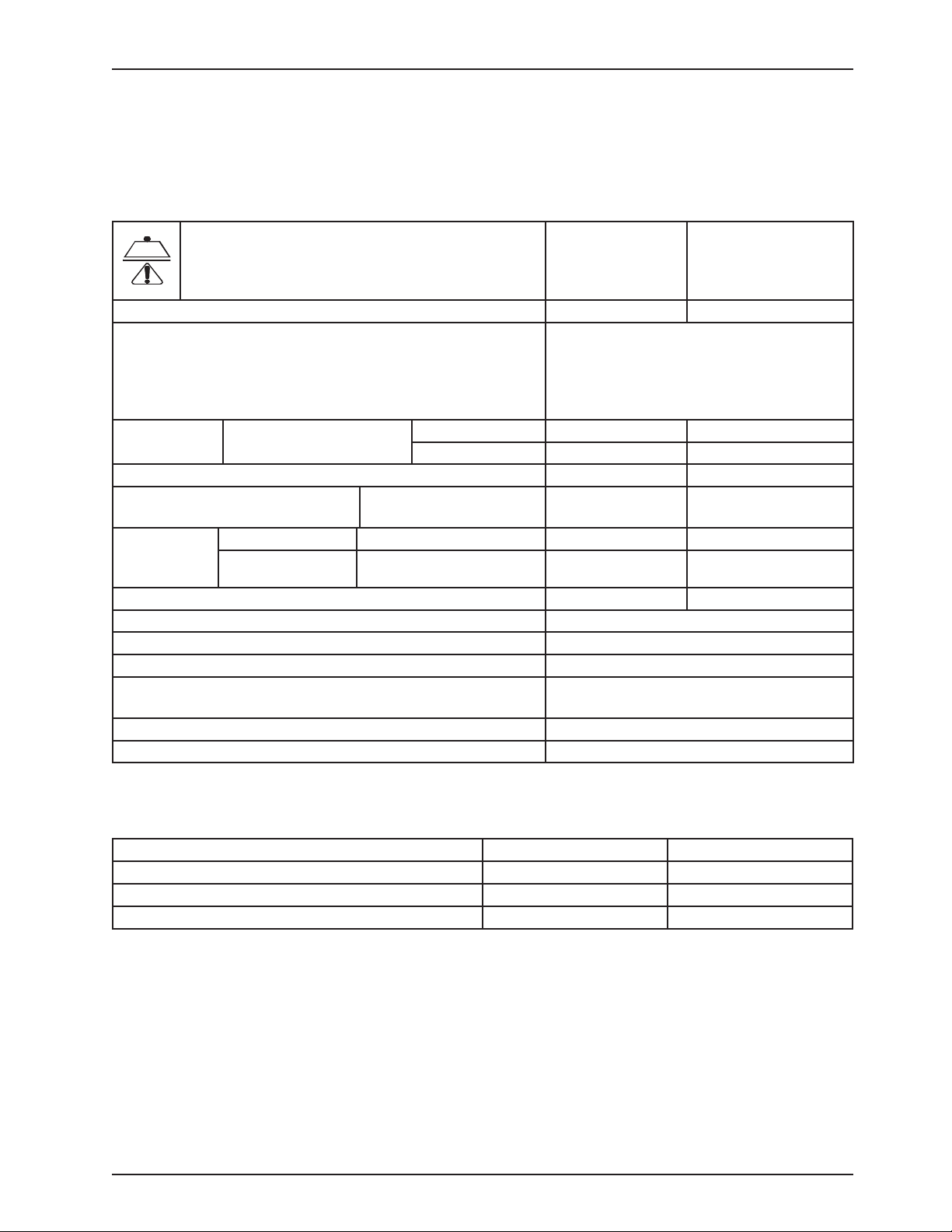
SPECIFICATIONS
Safe Working Load
Note: Safe Working Load indicates the sum of the
patient, mattress, and accessory weight.
Scale System Capacity (optional equipment). Loads weighing up to 500 lbs 227 kg
Scale System Accuracy (optional equipment) ± 2 pounds at 0° - ± 10° Trendelenburg for
Overall Length/
Width
Patient Sleep Surface - Standard Bed 84” x 35” 213,4 cm x 89 cm
Bed Height to Top of Seat
Litter - 6” Casters
Litter Platform
to Top of
Siderail
Space Between Siderails (Full Up) 2-1/4” 5,72 cm
Knee Gatch Angle 0° to 45°
Fowler Angle 0° to 60°
Trendelenburg/Reverse Trendelenburg +12° to -10° ± 1°
Electrical Requirements - all electrical requirements meet UL 2601
specifications.
Battery Voltage (1) 9V Nurse Call Option (Alkaline Battery)
Outlet Option 115 VAC, 60 Hz, 10.0 A
Standard Bed Siderails Up 93” x 42-1/2” 236,2 cm x 105,4 cm
Siderails Down 93” x 39-1/2” 236,2 cm x 100,3 cm
Standard 16” to 30” ±0.5 40,6 cm to 76,2 cm
Full Up Head End Siderail 15” 38,1 cm
Full Up Foot End Siderail 15 -1/2” 39,37 cm
500 lbs 227 kg
patients weighing 100 pounds or less
± 2% of the total patient weight at 0° - ± 10°
Trendelenburg for patients weighing greater
than 100 pounds
115 VAC, 60 Hz, 8.0 A
MATTRESS SPECIFICATIONS
Thickness 6” 15,2 cm
Width >= 35” >= 88,9 cm
Length >= 84” >= 213,4 cm
ILD 80 lbs 36.3 kg
The above stated mattress specifications assist in ensuring the product conforms to HBSW and IEC
specifications.
Return To Table of Contents
www.stryker.com 300 6- 009 -102 REV C 7
Page 8
Introduction
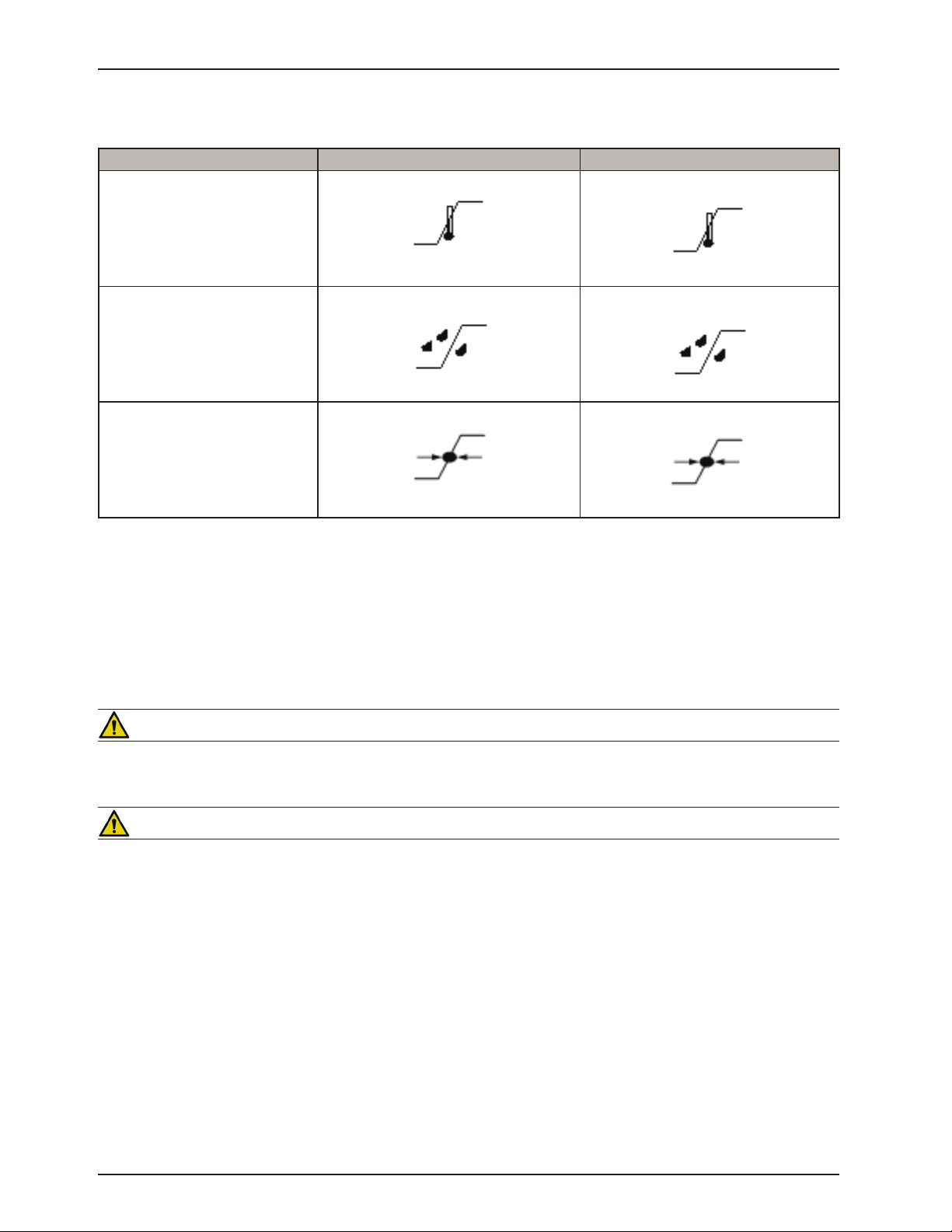
ENVIRONMENTAL CONDITIONS
Environmental Conditions Operation Storage and Transportation
40 0C
(104 0F)
Ambient Temperature
Relative Humidity
(Non-Condensing)
Atmospheric Pressure
Stryker reserves the right to change specifications without notice.
Specifications listed are approximate and may vary slightly from unit to unit or by power supply fluctuations.
10 0C
(50 0F)
30%
700 hPa
-30 0C
(-22 0F)
75%
10%
1060 hPa
500 hPa
60 0C
(140 0F)
95%
1060 hPa
WARNING/CAUTION/NOTE DEFINITION
The words Warning, Caution and Note carry special meanings and should be carefully reviewed.
WARNING
Alerts the reader about a situation, which if not avoided, could result in death or serious injury. It may also describe
potential serious adverse reactions and safety hazards.
CAUTION
Alerts the reader of a potentially hazardous situation, which, if not avoided, may result in minor or moderate injury to
the user or patient or damage to the equipment or other property. This includes special care necessary for the safe
and effective use of the device and the care necessary to avoid damage to a device that may occur as a result of use
or misuse.
Note
This provides special information to make maintenance easier or important instructions clearer.
Return To Table of Contents
8 3006 -009-102 REV C www.stryker.com
Page 9
Bed Illustration
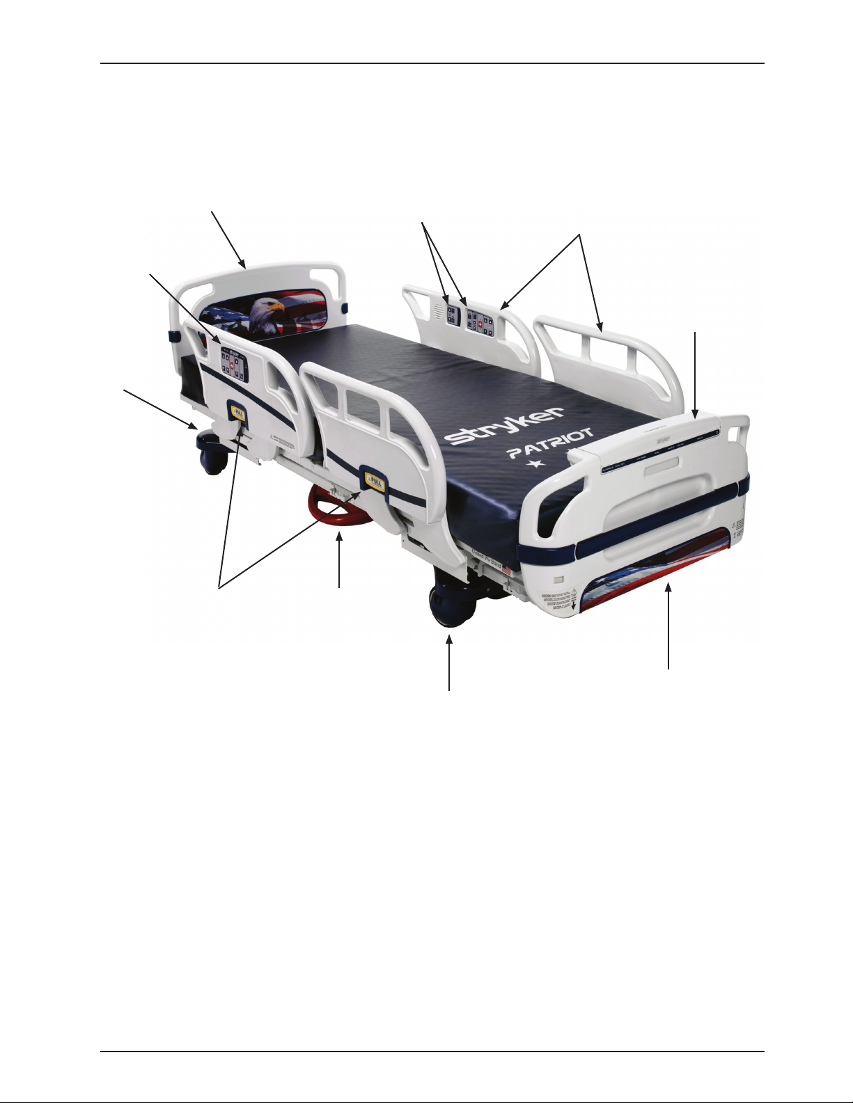
Control Panel
Steer
Pedal
(not
shown)
Nurse
Siderail Release
Headboard
Handle
Brake
Pedal
Patient
Control Panel
Siderail
Footboard
Control Panel
Footboard
Caster
Return To Table of Contents
www.stryker.com 300 6- 009 -102 REV C 9
Page 10
Symbols
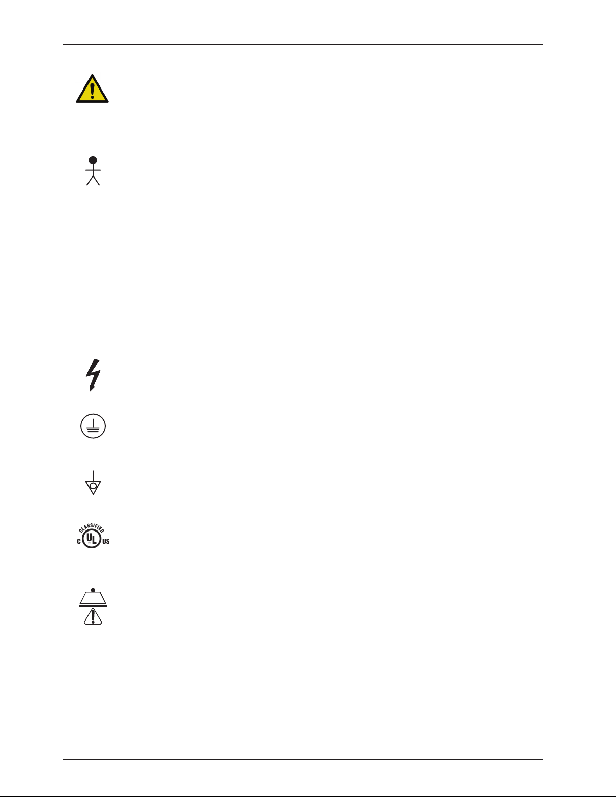
~
Warning, consult accompanying documentation
Alternating Current
Type B Equipment: equipment providing a particular degree of protection against electric shock,
particularly regarding allowable leakage current and reliability of the protective earth connection.
Class 1 Equipment: equipment in which protection against electric shock does not rely on BASIC
INSULATION only, but which includes an additional safety precaution in that means are provided for the
connection of the EQUIPMENT to the protective earth conductor in the fixed wiring of the installation in
such a way that ACCESSIBLE METAL PARTS cannot become live in the event of a failure of the BASIC
INSULATION.
Mode of Operation: Continuous
IPX4
Protection from liquid splash
Dangerous Voltage Symbol
Protective Earth Terminal
Potential` Equalization Symbol
Medical Equipment Classified by Underwriters Laboratories Inc. with Respect to Electric Shock, Fire,
Mechanical and Other Specified Hazards Only in Accordance with UL 60601-1, First Edition (2003) and
CAN/CSA C22.2 No. 601.1-M90 with updates 1 and 2.
Safe Working Load Symbol
Return To Table of Contents
10 300 6- 009 -102 REV C ww w.stryker.com
Page 11

Safety Tips and Guidelines
Before operating the 3002 S3 MedSurg Bed, it is important to read and understand all information in this manual.
Carefully read and strictly follow the safety guidelines listed on this page. It is important that all users have been trained
and educated on the inherent hazards associated with the usage of electric beds.
WARNING
To prevent permanent damage to this unit, the unit must reach room temperature prior to conducting any setup •
and/or unit operations.
Danger: Explosion hazard. Do not use in the presence of flammable anesthetics. Always apply the caster brakes •
when a patient is getting on or off the bed.
Always keep the caster brakes applied when a patient is on the bed (except during transport). After the brake •
pedal is applied, push on the bed to ensure the brakes are locked. Serious injury could result if the bed moves
while a patient is getting in or out of bed.
Ensure the brakes are completely released prior to moving the unit. Attempting to move the unit with the brakes •
actuated could result in injury to the user and/or patient.
Do not attempt to move the foot end of the bed laterally when the steer pedal is activated. When the steer pedal •
is activated, the steer caster at the foot end of the bed cannot swivel. Attempting to move the bed laterally when
the steer pedal is activated may cause injury to the user.
The 3002 S3 MedSurg Bed is not intended for use with patients less than two years of age. •
Serious injury can result if caution is not used when operating the unit. Operate the unit only when all persons are •
clear of the electrical and mechanical systems.
To help reduce the number and severity of falls by patients, always leave the bed in the lowest position when the •
patient is unattended.
When attaching equipment to the frame, ensure it will not impede normal frame operation. For example: hooks •
on hanging equipment must not actuate control buttons, equipment must not hide the nurse call button, foley bags
must not rest on brake pedal, etc. Use only a Stryker supplied interface cable. Use of any other cable may cause
the bed to function improperly, which may result in patient or user injury.
The 3002 S3 MedSurg Bed is equipped with a hospital grade plug for protection against electric shock hazard. It •
must be plugged directly into a properly grounded three prong receptacle. Grounding reliability can be achieved
only when a hospital grade receptacle is used.
When raising the siderails, listen for the “click”. When raising the siderail, the first click will indicate you can return •
to the intermediate position, the second click indicates its full up position. Once in position, move siderail from
side to side to ensure it is locked into position. Siderails are not intended to be a patient restraint device. It is the
responsibility of attending medical personnel to determine the degree of restraint and the siderail positioning to
ensure a patient will remain safely in bed.
The Bed Exit System is intended only to aid in the detection of a patient exiting the unit. It is NOT intended •
to replace patient monitoring protocol. The bed exit system signals when a patient is about to exit. Adding or
subtracting objects from the frame after zeroing the weigh system may cause a reduction in the sensitivity of the
bed exit system.
Before servicing or cleaning the bed, • always unplug the bed power cord from the wall socket. When working under
a bed in the high position, always place blocks under the litter frame and apply the brakes to prevent injury in case
the Bed Down switch is accidently pressed.
To avoid pinching your fingers, place the I.V. pole in the upright position before using the drive handle. •
When using any mattress and/or mattress overlay that increases the overall height greater than 6,” extra caution •
and/or operator supervision is required to help reduce the likelihood of a patient fall occurring.
Return To Table of Contents
www.stryker.com 300 6- 009 -102 REV C 11
Page 12

Safety Tips and Guidelines
WARNING (CONTINUED)
To avoid possible injury and to assure proper operation when using a powered mattress replacement system such as
XPRT:
Confirm• proper scale system operation following mattress installation. For best results, secure the therapy mattress
power cord to prevent damage to the cord or interference with the bed frame and the scale system.
Do not zero bed scales or weigh patient with Percussion, Vibration, Rotation or Turn Assist active. Patient motion •
and position resulting from the dynamic therapy mattress may adversely affect scale system performance.
Do no initialize (“arm”) bed exit with Percussion, Vibration, Rotation or Turn Assist active. The patient motion and •
position resulting from the dynamic therapy mattress may adversely affect bed exit system performance.
When using an XPRT or Position PRO Mattress, extra caution and/or operator supervision is required to help •
reduce the likelihood of a patient fall occurring.
CAUTION
When large spills occur in the area of the circuit boards, 110 volt cables and motors, immediately unplug the bed •
power cord from the wall socket. Remove the patient from the bed and clean up the fluid. Have maintenance
completely check the bed. Fluids can affect the operational capabilities of any electrical product. DO NOT put
the bed back into service until it is completely dry and has been thoroughly tested for safe operation.
Preventative maintenance should be performed at a minimum of annually to ensure all bed features are functioning •
properly. Close attention should be given to safety features including, but not limited to, safety side latching
mechanisms, frayed electrical cords and components, all electrical controls returning to the off or neutral position
when released, caster braking systems, no controls or cabling entangled in bed mechanisms, leakage current 300
microamps maximum, scale and bed exit systems calibrated properly, and the siderail gas spring not leaking oil.
Because individual beds may have different options, footboards should not be moved from one bed to another. •
Mixing footboards could result in unpredictable bed operation.
The lockout buttons on the footboard lock the Fowler, Gatch and Bed Up/Down functions and prevent motion of •
the bed. It is the responsibility of attending medical personnel to determine whether these functions should be
locked and to use the buttons accordingly.
The maximum safe working load for each I.V. pole is 40 pounds. •
I.V. Poles should not be used as a bed push/pull device.•
Scale function may be affected by siderail/caster interference. With the litter fully lowered or lowered in Reverse •
Trendelenburg, the siderails tucked under the litter in the storage position and the casters turned, there is the
potential for interference between the siderail and the caster. Raise the siderails when lowering the litter to the full
down position to prevent the interference from causing the scale system to weigh inaccurately
The use of a mattress overlay may reduce the effectiveness of the siderail. •
The cleanliness and integrity of both ground chains must be maintained to minimize static build up and •
discharge.
Do not add or remove weight when the bed exit system is armed. •
There is a possible fire hazard when using half bed length type oxygen administering equipment. Ensure that the •
siderails are outside of the tent.
There is a possible fire hazard when used with oxygen administering equipment of other than the nasal or mask •
type. Lock the control at foot of bed when using oxygen administering equipment.
The weight of the foley bags placed on isolated bag hooks should not exceed five pounds.•
The weight of pumps placed on footboard pump holder should not exceed 45 pounds.•
Return To Table of Contents
12 30 06- 009 -102 REV C www.stryker.com
Page 13

Safety Tips and Guidelines
IBED AWARENESS OPTION
In addition to the previous warnings and cautions, all of the following warnings and cautions apply to units equipped
with the iBED Awareness option.
WARNING
The optional • i BED Awareness system only indicates the siderail position; it does NOT indicate if the siderail is
locked. It is the caregiver’s responsibility to ensure that the siderails are locked after every move and also before
leaving a patient in the room.
The optional • iBED Awareness system indicator lights are only an aid to the caregiver, and in no way replace the
caregiver’s responsibility of checking on patients. Caregivers should not rely on the lights to perform their duties.
Before arming the optional • iBED Awareness system, the nurse must physically verify that siderails are locked.
CAUTION
If the optional • iBED Awareness system is being used, ensure the bed is in the desirable state (iBED Awareness
ON and with the light green) before leaving the room.
If the optional • iBED Awareness system is being used and the iBED Awareness is alerting, do not turn off iBED
Awareness as the display information to troubleshoot the bed will get lost.
If the optional • i BED Awareness system is being used, use of accessories that cover the center and side alert lights
at the footboard are not recommended.
110V OPTION
In addition to the previous warnings and cautions, all of the following warnings and cautions apply to units equipped
with the 110V option.
Only use equipment with the following electrical specs: 110 VAC; 10A; 60Hz. Maximum total load drawn by •
equipment used in this receptacle outlet must not exceed 10A. The total system chassis risk current should not
exceed 300 microamps. Grounding continuity should be checked periodically.
To avoid risk of electrical shock, unplug all power cords before opening the service compartment, junction box or •
receptacle.
Do not use the optional 110V outlet for life sustaining equipment.•
Return To Table of Contents
www.stryker.com 300 6- 009 -102 REV C 13
Page 14
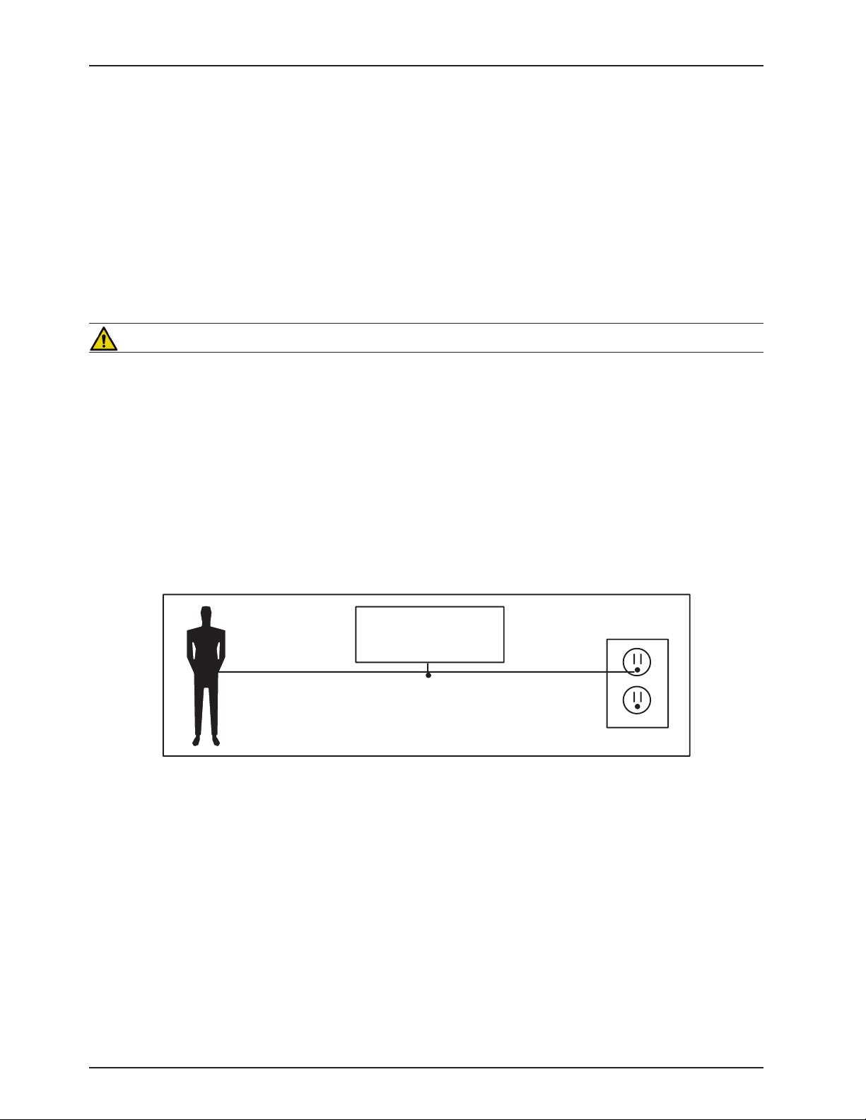
BED
GROUNDING DIAGRAM
Static Discharge Precautions
The electronic circuits in the Secure II Bed are completely protected from static electricity damage only while the bed
is assembled. It is extremely important that all service personnel always use adequate static protection when servicing
the electronic systems of the Secure II Bed. Whenever you are touching wires, you should be using static protection.
Static Protection Equipment
The necessary equipment for proper static protection is:
1 static wrist strap; 3M part number 2214 or equivalent,•
1 grounding plug; 3M part number 61038 or equivalent,•
1 test lead with a banana plug on one end and an alligator clip on the other; Smith part number N132B699 or •
equivalent.
CAUTION
All electronic service parts will be shipped in static shielding bags. Do not open the bags until you have completed
steps 2 and 3 of the following procedure. Do not place unprotected circuit boards on the floor. All circuit boards to be
returned to Stryker Medical should be shipped in the static shielding bags the new boards were shipped in.
Static Protection Procedure
Unplug the power cord from the wall receptacle.1.
Insert the grounding plug into a properly grounded hospital grade wall receptacle. Plug the banana plug of the 2.
test lead into the receptacle on the grounding plug. Connect the alligator clip on the other end of the test lead to
a ground point on the bed.
Place the static control wrist strap on your wrist. Connect the alligator clip at the other end of the wrist strap cord 3.
to a ground point on the bed.
Return To Table of Contents
14 3006 -00 9-102 REV C www.stryker.com
Page 15

Setup Procedures
To prevent permanent damage to this unit, the unit must reach room temperature prior to conducting any setup
and/or unit operations.
It is important that the S3 MedSurg Bed is working properly before it is put into service. The following list will help
ensure that each part of the bed is tested.
WARNING
The S3 MedSurg is equipped with a hospital grade plug for protection against electric shock hazard. It must be •
plugged directly into a properly grounded three prong receptacle. Grounding reliability can be achieved only when
a hospital grade receptacle is used.
Use only a Stryker supplied interface cable. Use of any other cable may cause the bed to function improperly •
which may result in patient or user injury.
Ensure there is no patient on the bed during the setup procedure. •
Plug the bed into a properly grounded, hospital grade wall receptacle and ensure the 1. LED light at the foot
end of the bed comes on.
Plug the optional interface cable into the 37 pin connector under the litter frame at the head end of the bed, into 2.
the “Patient Station”, “Head Wall”, “Docker Station”, or equivalent (whichever applies). Test the interface cable to
verify it is functioning properly.
Ensure the siderails raise, lower, lock in the up position, lock in the intermediate position when lowered and store 3.
smoothly (see Operations Manual for further details).
Ensure that all four casters lock when the brake pedal is engaged ((see Operations Manual for further details).4.
Raise the fowler (head of bed) up to approximately 605.
will drop with minimal effort.
Note
Ensure that the “Brake” LED located on the outside of the head end siderails and on the footboard control panel
blink when the brakes are not engaged.
0
. Squeeze the CPR release handle and ensure the back
Perform each function on the footboard control panel to ensure that each function is working properly (see 6.
Operations Manual for further details).
Perform each function on both head end siderails to ensure that each is working properly ((see Operations Manual 7.
for further details).
Activate the motion stop system to ensure it is functioning properly; press and hold down the BED DOWN key. 8.
As the bed lowers, push up on the motion interrupt pan under the bed and ensure the downward motion stops.
Release the pan and allow the downward motion to continue.
Note
The bed’s upward motion or other functions are not disrupted by the motion stop system.
If the bed is equipped with the Nurse Call option, verify it is functioning properly prior to patient use.9.
Return To Table of Contents
www.stryker.com 300 6- 009 -102 REV C 15
Page 16

Notes
Return To Table of Contents
16 3006- 009 -102 REV C ww w.stryker.com
Page 17

Cleaning
Hand wash all surfaces of the bed with warm water and mild detergent. Dry thoroughly. Do not steam clean or hose
off the Secure II Bed. Do not immerse any part of the bed. Some of the internal parts of the bed are electric and may
be damaged by exposure to water.
Suggested cleaners for bed surfaces:
Quaternary Cleaners (active ingredients - ammonium chloride)
Phenolic Cleaners (active ingredient - o-phenylphenol)
Chlorinated Bleach Solution (5.25% - less than 1 part bleach to 100 parts water)
Avoid over saturation and ensure the product does not stay wet longer than the chemical manufacturer’s guidelines
for proper disinfecting.
CAUTION
Some cleaning products are corrosive in nature and may cause damage to the product if used improperly. If the
products described above are used to clean Stryker patient care equipment, measures must be taken to ensure the
beds are wiped with a damp cloth soaked in clean water and thoroughly dried following cleaning. Failure to properly
rinse and dry the beds will leave a corrosive residue on the surface of the bed, possibly causing premature corrosion of
critical components. Failure to follow the above directions when using these types of cleaners may void this product’s
warranty.
For mattress cleaning instructions, please see the tag on the mattress, or contact the mattress manufacturer.
Clean Velcro® after each use. Saturate Velcro® with disinfectant and allow disinfectant to evaporate. (Appropriate
disinfectant for nylon Velcro® should be determined by the hospital.)
Return To Table of Contents
www.stryker.com 300 6- 009 -102 REV C 17
Page 18

Preventative Maintenance
__ __ _ Check fowler motor flexible mounting for damage or wear.
Beds require an effective maintenance program, we recommend checking these items annually. Use this sheet for
your records. Keep on file.
CHECKLIST
__ __ _ All fasteners secure (reference all assembly prints).
__ __ _ Engage brake pedal and push on the bed to ensure all casters lock securely.
__ __ _ Inspect the brake assembly (Brake Ratchet Spring and Brake Bar) for degradation or signs of wear at the
foot end and head end of the bed. Ensure brake assembly components (locking caster and springs) are
functioning properly.
__ __ _ “Brake” LED on the footboard and head end siderails blink when brakes are not engaged.
__ __ _ Locking steer caster engages and disengages properly.
__ __ _ Siderails move, latch and stow properly.
__ __ _ CPR release working properly.
__ __ _ F oot prop intact and working properly.
__ __ _ I.V. pole working properly.
__ __ _ Foley bag hooks intact.
__ __ _ Optional CPR board not cracked or damaged and stores properly.
__ __ _ No cracks or splits in head and footboards.
__ __ _ No rips or cracks in mattress cover.
__ __ _ All functions on head end siderails working properly (including LED’s).
__ __ _ All functions on footboard working properly (including LED’s).
__ __ _ Scale and Bed Exit system calibrated properly.
__ __ _ Motion Interrupt switches working properly.
__ __ _ Night light working properly.
__ __ _ Power cord not frayed.
__ __ _ No cables worn or pinched.
__ __ _ All electrical connections tight.
__ __ _ All grounds secure to the frame.
__ __ _ Ground impedance not more than 100 milliohms.
__ __ _ Current leakage not more than 300 microamps.
__ __ _ Apply grease to the Litter grease points and fowler motor clutch (see page 3 for locations).
__ __ _ Ensure ground chains are clean, intact, and have at least two links touching the floor.
__ __ _ Check Fowler angle for accuracy 00 - 600.
__ __ _ Siderail switches working properly (iBED Awareness option).
__ __ _ Center Light Bar LED and side light LED working properly (iBED Awareness option).
__ __ _ Inspect footboard control labeling for signs of degradation.
__ __ _ Inspect siderail gas spring for oil leaks and replace if necessary.
Bed Serial Number:
Completed by: _______________ __ __ __ __________________ Date: ________________ __ _
Return To Table of Contents
18 3006- 009 -102 REV C ww w.stryker.com
Page 19
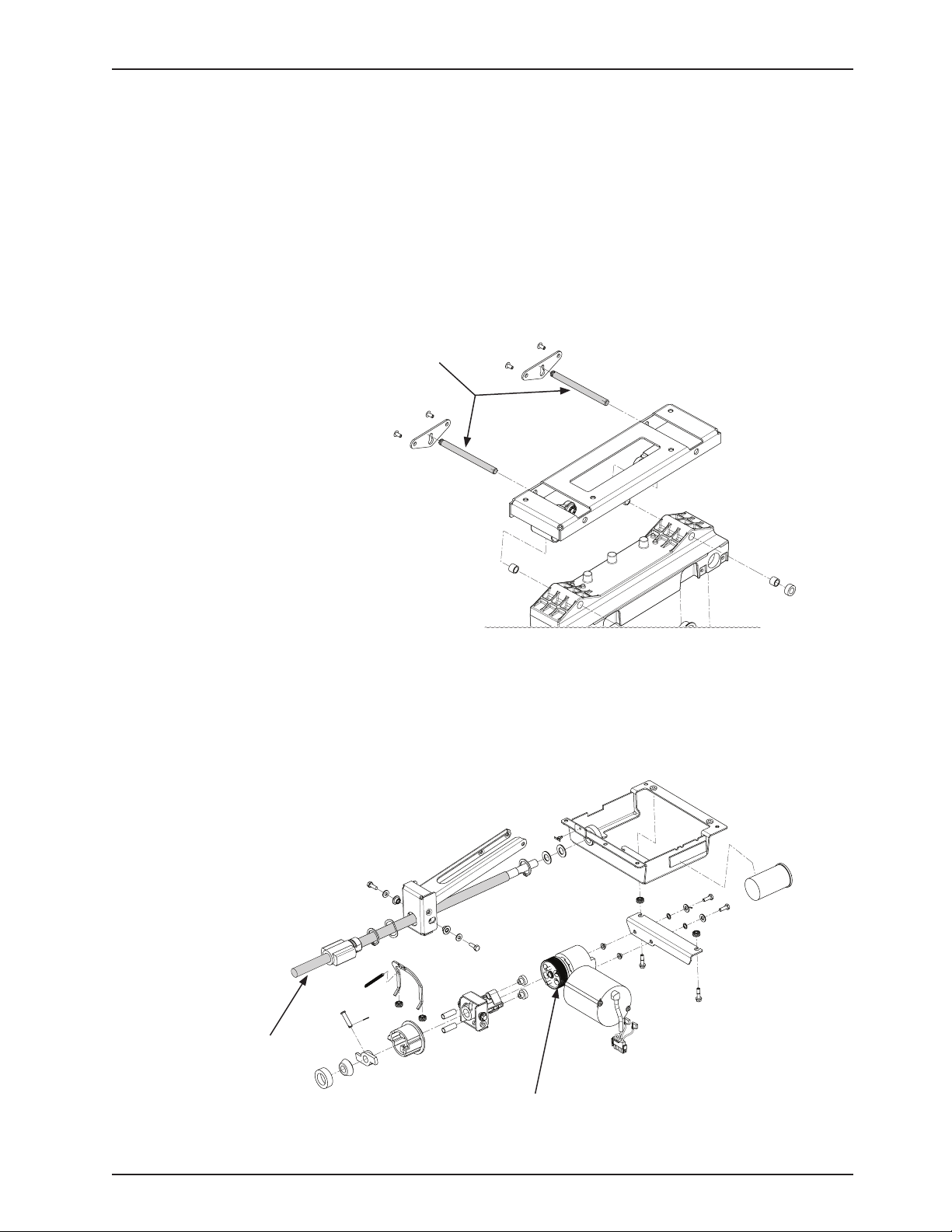
Preventative Maintenance
GREASE POINTS
H/E Glide Rod1.
Ball Screw2.
Brake Spring3.
Siderail Assembly (Reference p/n: 3006-400-105 (Head End) and 3006-400-300 (Foot End)
Apply Syn-Tech NS-18191-G grease (p/n 3000-200-700) to Glide Rod surface.1.
Glide Rod
Fowler Drive Assembly (Reference p/n: 3006-300-550)
Apply Mobile #28 grease to the entire length of the ball screw.1.
If dry, apply a thin film layer of Syn-Tech grease (p/n 3000-200-700) to the outside of the brake spring. 2.
Head End
shown
Ball Screw
Brake Spring
Return To Table of Contents
www.stryker.com 300 6- 009 -102 REV C 19
Page 20

Troubleshooting Guide
Note
See the “Bed Circuit Boards” section for an outline of bed PCB’s and voltage test points.
Problem / Failure Recommended Action
No power to bed. Verify the power cord connections at the wall and the A.
bed.
Check the circuit breakers under the Litter/Fowler B.
section on the patient’s left side. If the circuit breaker
is tripped, reset it by pushing in.
Check for 120VAC at J1 on the power supply, Pin 1 C.
and 2.
Check for DC voltages on J2 (Pins 1, 2, 3 & 6) on D.
power supply. See “Power Supply” in the Bed Circuit
Boards section for power supply voltage test points.
If voltage is present, check connector W on the a.
CPU board and check for the same DC voltages.
If OK, go to step E.
If voltage is not present, unplug connector W on b.
the CPU board and recheck for DC voltages at J2
on the power supply.
If voltages come back, re-connect cable W to 1.
the CPU board and go to step C.
If DC voltage does not come back, replace 2.
the power supply.
Unplug all connectors except for F, FF, O, and a.
W from the CPU board and recheck voltages on
connector W.
If DC voltages come back, plug the cable 1.
connections back in until problem comes
back, isolate the problem to a component or
assembly.
If DC voltages do not come back, replace the 2.
CPU board.
Check for 120VAC at connector O on the CPU board.E.
If voltage is present, replace CPU board.a.
If the CPU board has been replaced, reconfigure the F.
bed by resetting the: Bed Type, Bed Options, Serial
Number, Burn-in Limits (Fowler and Height) and
calibrating the scale.
Verify bed function and return to service. G.
Return To Table of Contents
20 300 6- 009 -102 REV C ww w.stryker.com
Page 21

Problem / Failure Recommended Action
No bed down motion.
No bed up motion.
Troubleshooting Guide
Enter diagnostics (see Scale System Diagnostics and A.
Calibration section) and press bed down.
If motion is not present, verify the two wire a.
connection is present on connector Z.
Test bed down motion; if motion is present 1.
then go to step D.
If motion is present, re-burn lift potentiometer limits b.
(see Lift Potentiometer “Burn-In” Procedure).
Check for 5VDC on TP 9 (HL) and TP 7 (FL); reference B.
ground test point while pushing the bed down button.
If 5VDC is present, go to step C.a.
If 5VDC is not present, replace CPU board.b.
Check for 120VAC power on connector N (HL) and G C.
(FL), pin 1 white and pin 3 black, of the CPU board,
while pressing bed motion up.
If voltage is not present, replace CPU board.a.
If voltage is present:b.
Verify the motors are running, if so, replace 1.
lift couplers.
If motors are not running, check voltage at 2.
motor connection.
If voltage is present at motor, check capacitors 3.
or motors.
Verify bed function and return to service.D.
Enter diagnostics (see Scale System Diagnostics and A.
Calibration section) and press bed up.
If motion is not present, got to step B.a.
If motion is present, re-burn lift potentiometer limits b.
(see Lift Potentiometer “Burn-In” Procedure).
Check for 5VDC on TP 10 (HL) anf TP 8 (FL) on the B.
CPU board; reference ground test point while pushing
the bed up button.
If 5VDC is present, go to step C.d.
If 5VDC is not present, replace CPU board.e.
Check for 120VAC power on connector N (HL) and G C.
(FL), pin 1 white and pin 6 red, of the CPU board while
pressing bed motion up.
If voltage is not present, replace CPU board.a.
If voltage is present:b.
Verify the motors are running, if so, replace 1.
lift couplers.
If motors are not running, check voltage at 2.
motor connection.
If voltage is present at motor, check capacitors 3.
or motors.
Verify bed function and return to service.D.
Return To Table of Contents
www.stryker.com 300 6- 009 -102 REV C 21
Page 22

Troubleshooting Guide
Problem / Failure Recommended Action
No Gatch down motion.
No Gatch up motion.
No Fowler up motion.
No Fowler down motion. Check for 5VDC on TP 5 on the CPU board, reference A.
Check for 5VDC on TP4 on the CPU board; reference A.
ground test point while pushing the fowler down
button.
If 5VDC is present, go to step B.a.
If 5VDC is not present, replace CPU board.b.
Check for 120 VAC on connector GG, Pin 1 (white) B.
and pin3 (red), of the CPU board while pressing Fowler
down.
If voltage is not present, replace the CPU boarda.
If 5VDC is present, check the capacitor and b.
mo to r.
Verify bed function and return to service.C.
Check for 5VDC on TP 3 on the CPU board; reference A.
ground test point while pushing the fowler up button.
If 5VDC is present, go to step B.a.
If 5VDC is not present, replace CPU board.b.
Check for 120VAC on connector GG, Pin 1 (white) and B.
pin 2 (black), of the CPU board while pressing Fowler
up.
If voltage is not present, replace the CPU boarda.
If 5VDC is present, check the capacitor and b.
mo to r.
Verify bed function and return to service.C.
Check for 5VDC on TP 6 on the CPU board, reference A.
ground test point while pushing the gatch up button.
If 5VDC is present, go to step B.a.
If 5VDC is not present, replace CPU board.b.
Check for 120VAC on connector CC, pin 1 (black) and B.
pin3 (white), of the CPU board while pressing gatch
up.
If voltage is not present, replace the CPU boarda.
If 5VDC is present, check the capacitor and b.
mo to r.
Verify bed function and return to service.C.
ground test point while pushing the gatch down
button.
If 5VDC is present, go to step B.a.
If 5VDC is not present, replace CPU board.b.
Check for 120VAC power on connector CC, pin 2 (red) B.
and pin 3 (white), of the CPU board while pressing
gatch down.
If voltage is not present, replace the CPU board.a.
If 5VDC is present, check the capacitor and b.
mo to r.
Verify bed function and return to service.C.
Return To Table of Contents
22 300 6- 009 -102 REV C ww w.stryker.com
Page 23
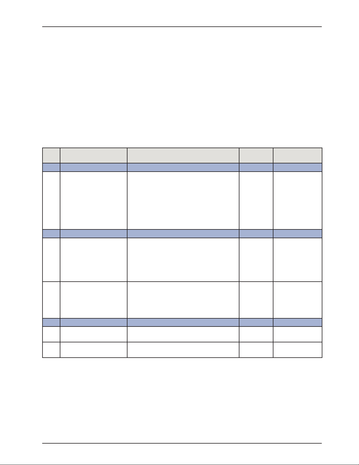
iBED Awareness System Error Codes
ERROR HANDLING
The error handling system provides a mechanism for capturing errors known to the product and providing feedback •
to the operator through logged errors or message errors.
All Logged errors generate a generic blinking error message which will be displayed on the status screen in the •
lower area: “Error XXX Call Service”, where XXX is the error code.
Errors will only be logged if the error log does not already contain the error.•
In the event multiple errors are displayed on the status screen, the error code is used to identify the priority. The •
lowest code has the highest priority.
All logged errors and message errors are persistent until the power is cycled or the condition is fixed. •
The details for each logged error and error message are detailed in the table below.•
LOGGED ERRORS
Error
Code
000 Not Used High Priority Exceptions
090 Brake Switch Error This error is checked while the product is
100 Not Used Highest Priority Errors
102 StuckSafetyRelay This error is checked while the product is
103 InputTimer If any footboard motion or side rail/pendant
200 Not Used Scale System
201 HL-Load Cell Patient Head Left Load Cell. Under/Over
202 HR-Load Cell Patient Head Right Load Cell. Under/Over
Name Description Ty p e Affected Systems
“On.” If one of the two brake wires is disconnected or shorted to 5V then the exception message is shown immediately or upon
a change in the brake state. This error shall
persist on the display until both the power
is cycled and the error condition has been
fixed.
“On”. If the safety relay signal is “On” and
there is no button pressed on the product
then set this error after 1 minute.” Note: This
should not be checked when in Auto-Cycle
Mode.
input is sensed to be “On” continuously for a
total of 5 minutes then provide an exception
message. Note: This should not be checked
when in Auto-Cycle Mode.
range.
range.
Logged Brake
Logged Motion
Logged Motion
Logged Scale, Bed Exit,
iBED Awareness
Logged Scale, Bed Exit,
iBED Awareness
Return To Table of Contents
www.stryker.com 300 6- 009 -102 REV C 23
Page 24
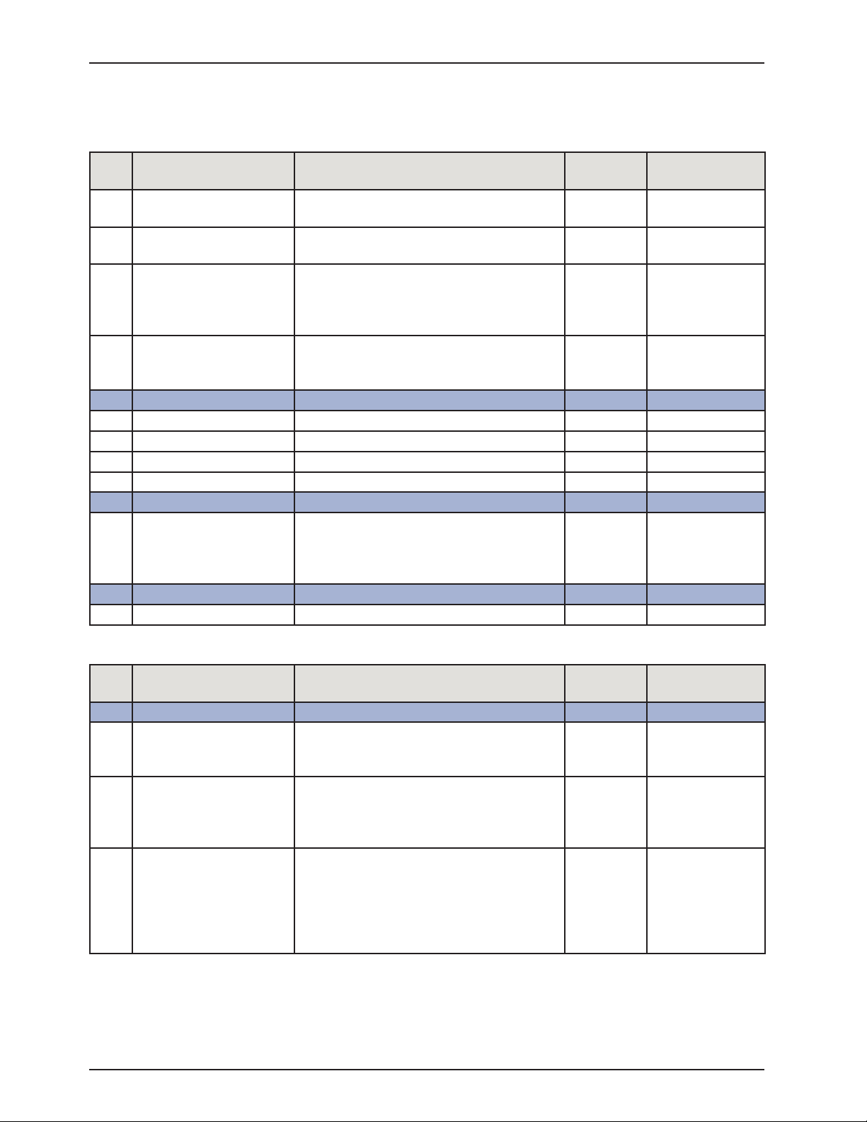
iBED Awareness System Error Codes
LOGGED ERRORS (CONTINUED)
Error
Code
203 FL-Load Cell Patient Foot Left Load Cell. Under/Over
204 FR-Load Cell Patient Foot Right Load Cell. Under/Over
206 CS5533Fatal Non-Recoverable Communication Error.
207 ZeroFail Zero Fail error occurs when the system can-
300 Not Used Side Rails
301 HLSRSwitch Head Left Side Rail Switch General. Logged iBED Awareness
302 HRSRSwitch Head Right Side Rail Switch General. Logged iBED Awareness
303 FLSRSwitch Foot Left Side Rail Swtich General. Logged iBED Awareness
304 FRSRSwtich Foot Right Side Rail Switch General. Logged iBED Awareness
400 Not Used Memory System
401 EEPROM EEPROM Memory Corruption
500 Not Used Motion System
Name Description Ty p e Affected Systems
Logged Scale, Bed Exit,
range.
Logged Scale, Bed Exit,
range.
Logged Scale, Bed Exit,
CS5533 Fatal occurs when the CPU fails
to communicate to the External ADC for the
Load cells and cannot recover.
Logged Scale, Bed Exit,
not provide a stable zero value for three consecutive attempts at zeroing the product.
Logged
Any detected non recoverable memory failure
will produce an error and localize the error to
a section of memory.
iBED Awareness
iBED Awareness
iBED Awareness
iBED Awareness
ERROR MESSAGES
Error
Code
800 Not Used Non-Logged Errors
801 NurseCallBattery When the nurse call battery falls below the 5v
803 FowlerCalibration When the fowler calibration has not been
804 ScaleCalibration Scale Calibration error occurs when the
Name Description Ty p e Affected Systems
threshold a message will appear in the lower
status window “N/C Battery Low”.
completed then when in normal mode the
message “Fowler Calib. Err” will be displayed
in the lower status screen window.
product in a normal operation mode and the
scale system is present on the product but
the scale system has not been calibrated. The
message “Scale Calib. Err” will be displayed
in the lower status screen window.
Non-Logged N/A
Non-Logged N/A
Non-Logged N/A
Return To Table of Contents
24 300 6- 009 -102 REV C www.stryker.com
Page 25

iBED Awareness System Error Codes
ERROR MESSAGES (CONTINUED)
NOTE: The 900 error codes are not logged.
Error
Code
900 Not Used Message Errors
901 ScaleSystem When turning on the Scale system, using the
902 BedExitSystem When turning on the Bed Exit system if a
903 LBSSystem When turning on the iBED Awareness system
Name Description Ty p e Affected Systems
- When the timeout for the message error has
expired the display should return to the status
screen unless otherwise noted or unless a
higher priority screen is being handled.
Scale Button, if a “Logged” error is present
that affects the scale system (see affected
systems column) the message “Function
Disabled - Call Service” will blink.
“Logged” error is present that affects the
scale or bed exit systems (see affected
systems column) the message “Function
Disabled - Call Service” will blink.
Bed Exit will alarm if Bed Exit is armed and a
200 level exception occurs. The message will
be displayed “Turn off Bed Exit - Call Service”.
When the system is disarmed, the display will
go back to the status screen. Since the bed
exit alarm has the highest priority, if the Bed
Exit alarm is tripped due to the error condition
this message will not be seen.
if a “Logged” error is present that affects
the iBED Awareness system (see affected
systems column) the message “Function
Disabled - Call Service” will blink.
System N/A
Message N/A
Message N/A
iBED Awareness will alarm if iBED Awareness
is “On” and a 200 or 300 level Logged error
occurs. The message will be displayed “Turn
off Awareness - Call Service”, When the
system is turned off, the display will go back
to the status screen.
904 UnknownBedType Unknown bed type occurs when the
configuration switch bank does not contain
a value that is recognized by the software.
This will cause the product to stop all function
and product a message screen indicating the
error number and the message “Unknown
Bed Type - Call Service”
www.stryker.com 300 6- 009 -102 REV C 25
Message N/A
Return To Table of Contents
Page 26

iBED Awareness System Error Codes
ERROR MESSAGES (CONTINUED)
Error
Code
905 CANConnectivity If the footboard does not see the Main board
906 ScaleFeatures A message will be displayed when user tries
907 ZeroAttemptFailed The “Unable to Zero - Try Again” message
910 LoadCellCheck The load cells will be checked when the
911 MenuException If the footboard menu system is provided with
912 CalibrationException If the scale calibration routine fails then the
Name Description Ty p e Affected Systems
Heart beat within 10 seconds then the message “Communication Failed - Call Service”
to activate any scale function (Ex. Gain/Loss,
Change Equipment…) that is disabled due
to a logged scale exception (200 Series).
Message “Function Disabled - Call Service”
at 0.8 Hz (70% Duty Cycle) for 4 seconds.
will flash be displayed when the user tries to
zero the bed and the scale system cannot
stabilize the weight in time. Note: This applies
to any use of the zeroing feature, even if that
is within another scale function.
If a zero attempt has failed then the scale
system will be suspended until a successful
zero is saved or the power is cycled. If the
scale button is pressed the “Function Not
Available - Zero Bed” message will flash.
maintenance menu is entered and a message
will be displayed if any load cell errors are
detected. The message should be displayed
“Load Cell Error – HL HR FL FR”. Note: Only
the load cells that are in error will be displayed.
This message will be persistent until any of
the menu type buttons are pressed.
data that is out of range the display will present “Menu Error – Call Service”. The message
will persist until a menu state is correct.
message “Calibration Error” will be displayed
for 4 seconds and then return to the maintenance menu.
Message N/A
Message N/A
Message N/A
Message N/A
Message N/A
Message Motion
Return To Table of Contents
26 3006- 009 -102 REV C www.stryker.com
Page 27

Quick Reference Replacement Parts List
Note
The parts and accessories listed on this page are all currently available for purchase. Some of the parts identified on
the assembly drawing parts in this manual may not be individually available for purchase. Please call Stryker Customer
Service USA: 1-800-327-0770 for availability and pricing.
Part Name Part Number
Electrical Components
Footboard Keyboard (S/R Lights, Lockouts, etc.) 3006-553-011
CPU Board 3006-307-950
Power Supply 0059-157-000
Siderail Board, Inside 3006-400-930
Siderail Board, Outside 3006-400-910
Siderail Speaker with Cable 3000-403-831
Night Light Circuit Board 3002-310-900
Other Components
Beeper Kit, Bed Exit, Low Sounding 3002-700-029
Beeper Kit, Bed Exit, High Sounding 3002-700-030
Capacitor, Fowler 0059-785-000
Capacitor, Gatch 0059-783-000
Capacitor, Lift 0059-786-000
Caster, 6” 3001-200-060
Caster, Steer, 6” 3001-200-050
Coil Cord, Lift Power 3001-200-824
Coil Cord, Lift Sensor 3006-200-815
Coil Cord, Litter Power 3001-300-844
Coil Cord, Litter Signal 3006-300-808
Fowler Brake Kit 3001-300-775
Load Cell 3002-307-057
Return To Table of Contents
www.stryker.com 300 6- 009 -102 REV C 27
Page 28

Quick Reference Replacement Parts List
Part Name Part Number
Other Components (Continued)
Motor Coupler Kit, Lift 3000-200-725
Motor, Fowler with Clutch 3004-700-106
Motor, Fowler with Clutch, Short Bed 3004-700-108
Motor, Gatch 3003-016-602
Motor, Lift (Same for Head and Foot End) 3003-016-603
Paint, Touch-Up, Bottle with Brush 7000-001-321
Paint, Touch-Up, Spray Can 7000-001-318
Potentiometer, Foot End 3001-200-230
Potentiometer, Head End 3006-200-240
Power Cord 3002-700-049
Single Tube of Grease 3000-200-700
Head/Footboard “C” Bumper Adhesive 0072-002-071
Fowler Pentiometer 3001-345-807
Return To Table of Contents
28 3006- 009 -102 REV C www.stryker.com
Page 29
Service Information
BRAKE PEDAL REPLACEMENT
TOOLS REQUIRED:
5/16” Hex Allen Wrench•
Torque Wrench•
Bungee Cords•
Loctite 242•
Hammer•
Punch•
#2 Phillips Screwdriver•
PROCEDURE:
Raise the bed to the full upright position.1.
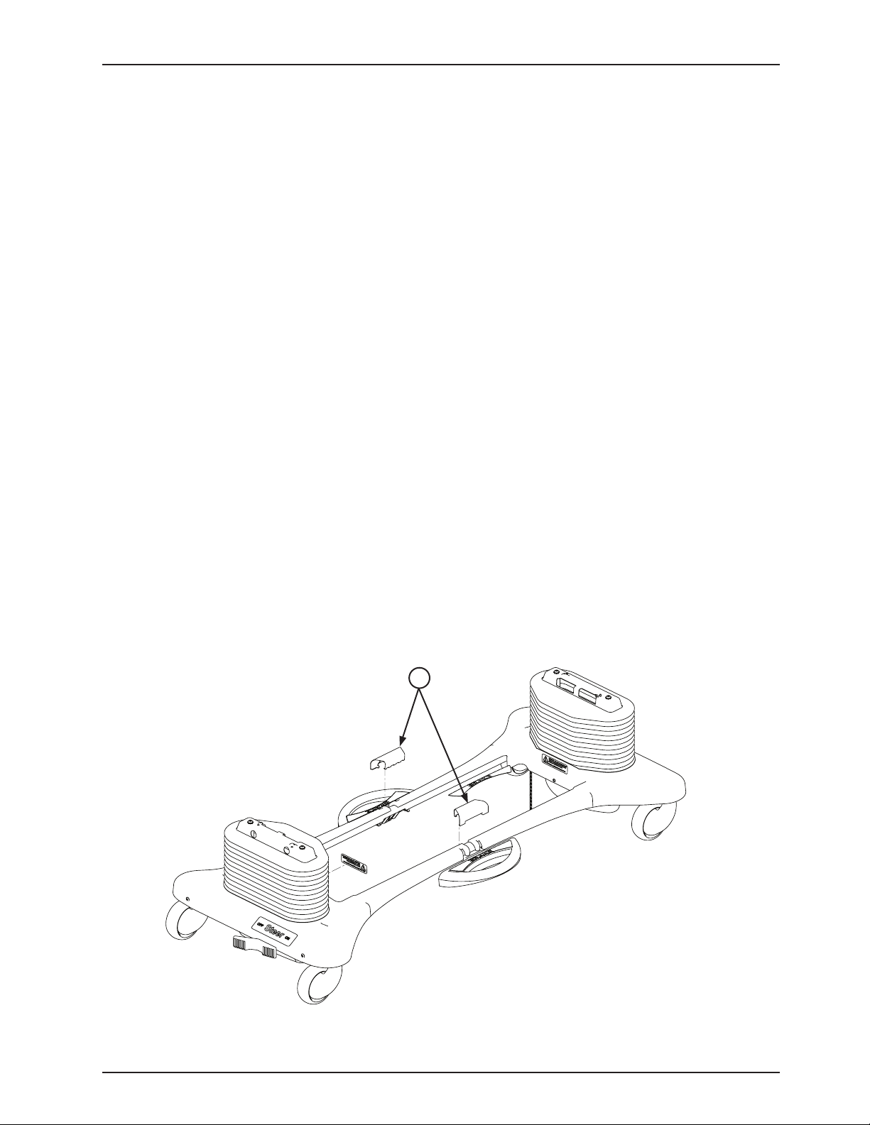
Remove the two uni-pan cover clips (A) holding the uni-pans together.2.
Unplug the bed power cord from the wall socket.3.
Using a #2 Phillips screwdriver, remove the three screws holding both the head end and the foot end upper lift 4.
covers. If desired, hold the covers out of the way by using bungee cords (or the equivalent) to secure them to the
litter top.
Using a 5/16” hex Allen wrench, remove the two bolts holding the brake pedal to the brake rod on the side which 5.
needs to be changed.
Using a hammer and punch, remove the roll pins holding the brake shaft crank to the brake rod on both the head 6.
and the foot end.
Push the brake rod through the frame until the brake pedal is clear. Remove the brake pedal.7.
Reverse the above steps to attach the new brake pedal.8.
Note
Use Loctite 242 when reinstalling the bolts and torque the bolts to 25 foot-pounds.
A
Return To Table of Contents
www.stryker.com 300 6- 009 -102 REV C 29
Page 30
A
B
D
FOOT END
C
Service Information
LIFT MOTOR AND CAPACITOR REMOVAL AND REPLACEMENT
TOOLS REQUIRED:
3/8” Socket Wrench w/Extension•
5/16” Socket Wrench•
Floor Jack•
Side Cutters•
7/16” Open End Wrench•
2x4 (or Equivalent)•
PROCEDURE:
Note
If you need more space to work under the base frame, place a 2 x 4 across the base frame rails and use a floor jack
to raise the base frame off the floor.
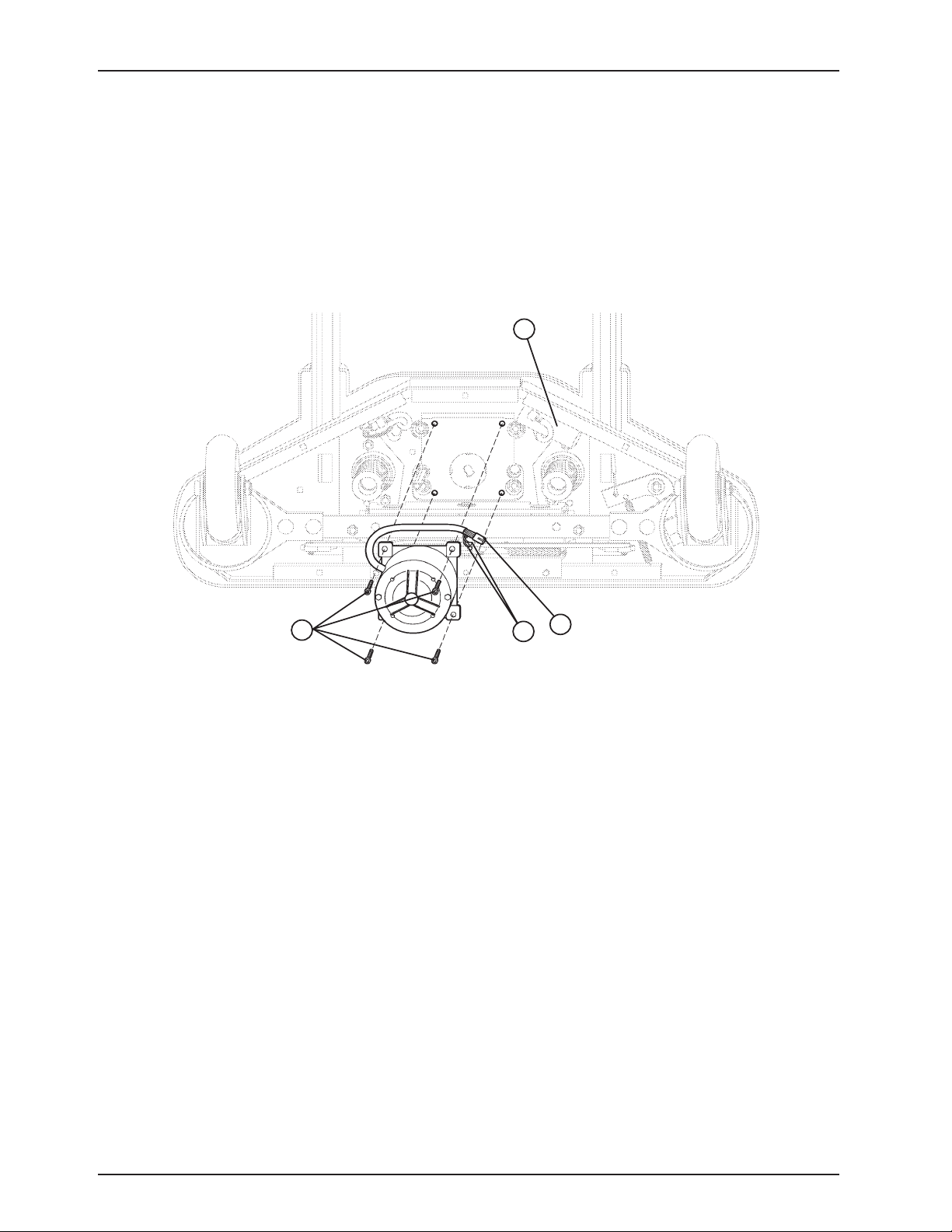
Unplug the bed power cord from the wall socket. Using a 5/16” socket wrench, remove the five bolts holding the 1.
lower lift cover to the base and remove the cover.
Disconnect the two connectors (A) at the motor capacitor.2.
Disconnect the white connector (B) from the power cord.3.
Using side cutters, cut the cable ties holding the capacitor (C) to the base and remove the capacitor.4.
Using a 3/8” socket wrench, remove the four screws (D) holding the motor assembly in the lift housing and remove 5.
the motor assembly.
Reverse the above steps to install the new motor.6.
Note
The drive shaft on the new motor probably will have to be turned to be aligned with the coupler. Use a 7/16” open end
wrench to turn the drive shaft of the motor.
The procedure for lift motor and capacitor removal and replacement is the same for both ends of the bed.
Return To Table of Contents
30 300 6-009 -102 REV C www.stryker.com
Page 31

Service Information
LIFT HOUSING REMOVAL AND REPLACEMENT
TOOLS REQUIRED:
#2 Phillips Screwdriver•
Bungee Cord (or equivalent)•
5/16” Socket Wrench•
Side Cutters•
9/16” Socket Wrench•
5/16” Nut Driver•
7/32” Hex Allen Socket Wrench•
Sawhorses (or equivalent)•
T27 Torx•
3/8” Socket Wrench (with approximately 6” extension)•
PROCEDURE:
Unplug the bed power cord from the wall socket.1.
Using a 5/16” socket wrench, remove the five bolts holding the lower lift cover to the base and remove the cover.2.
Remove the uni-pan cover clips.3.
Using a #2 Phillips screwdriver, remove the three screws holding the upper lift cover to the base.4.
If you are working on the foot end of the bed, use a T27 Torx to remove the screw holding the litter access panel 5.
to the litter.
Remove the lift motor and capacitor (6. refer to page 30 “Lift Motor and Capacitor Removal and Replacement”).
Remove lift potentiometer (7. refer to page 3 “Lift Potentiometer Replacement and Adjustment”).
Using a 5/16” socket wrench, remove the cable clamps holding the power and sensor coil cords on top of the lift 8.
housing assembly. Cut the cable ties and disconnect the coil cords from under the lift housing. The power and
sensor coil cords are now free of the lift housing assembly. Drape them up out of the way.
Using a 7/32” hex Allen socket, remove the two screws (A) holding the lift screws to the header crossbar plate.9.
CAUTION
The bed litter retracts on rollers. Secure it to prevent it from rolling while the procedure is being done.
Return To Table of Contents
www.stryker.com 300 6- 009 -102 REV C 31
Page 32
B
FOOT END − BOTTOM VIEW
Service Information
LIFT HOUSING REMOVAL AND REPLACEMENT (CONTINUED)
9. Lift the litter top up and support it about 6” above the lift screws with sawhorses or the equivalent.
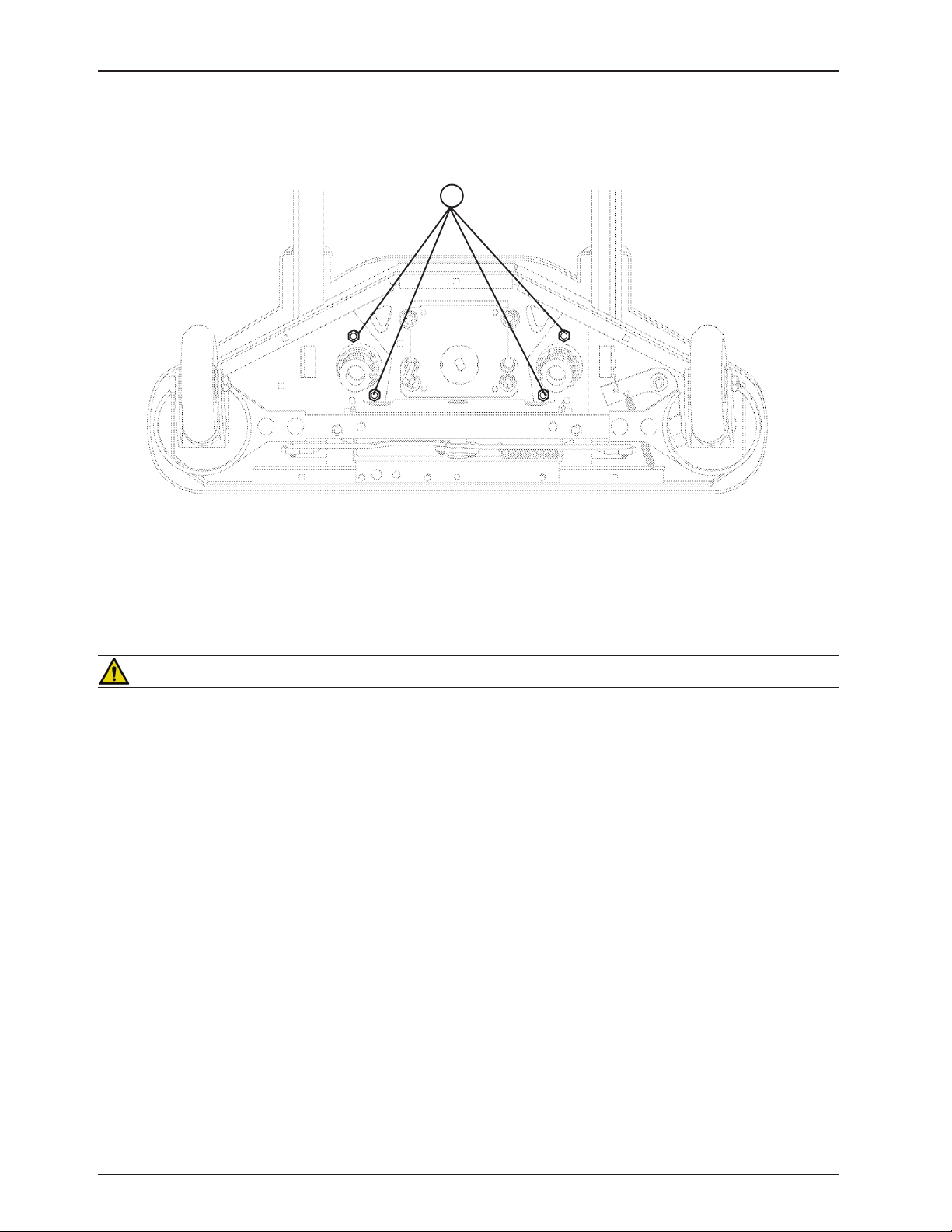
10. Under the base, using a 9/16” socket, remove the four nuts (B) holding the lift housing to the base.
11. Lift up and out on the lift housing assembly to remove it from the base.
CAUTION
Refer to page 37 “Power and Sensor Coil Cord Replacement” for proper reattachment procedure for power and
sensor coil cords and refer to page 3 “Lift Potentiometer Replacement and Adjustment” for reattachment of the lift
potentiometer.
12. Reverse the above steps to reinstall the lift housing assembly after service is completed.
Note
The procedure for lift housing removal and replacement is the same for both ends of the bed.
Return To Table of Contents
32 3006- 009 -102 REV C www.stryker.com
Page 33
B
C
A
B
Service Information
LIFT POTENTIOMETER REPLACEMENT AND ADJUSTMENT
TOOLS REQUIRED:
#2 Phillips Screwdriver•
Bungee Cord (or equivalent)•
5/16” Socket Wrench•
3/8” Open End Wrench•
Side Cutters•
PROCEDURE:
Raise the bed to the full upright position.1.
Unplug the bed power cord from the wall socket.2.
Using a 5/16” socket wrench, remove the five bolts holding the lower lift cover to the base and remove the cover.3.
Using a #2 Phillips screwdriver, remove the three screws holding the upper lift cover to the base.4.
Remove the uni-pan cover clips.5.
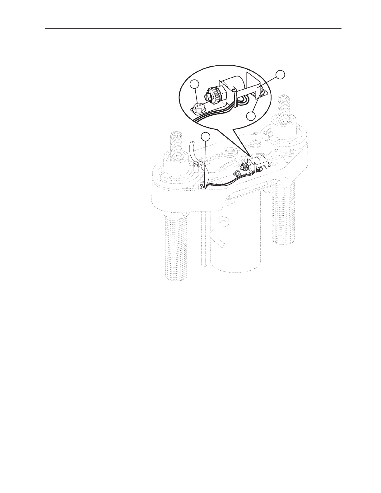
Using side cutters, cut the cable tie (A) holding the potentiometer cable to the coil cord.6.
Unplug the potentiometer cable from the sensor coil cord. If replacing a potentiometer at the head end of the bed, 7.
unplug the cables attached to the brake sensor switch.
Pull the potentiometer cable up through the base.8.
Using a 3/8” open end wrench, remove the two bolts (B) holding the potentiometer housing (C) to the lift 9.
housing.
Lift up and out on the potentiometer housing assembly to remove it from the lift housing.10.
Before installing the new potentiometer on the bed, turn it clockwise until it stops. Turn it back counterclockwise 11.
two full (360) revolutions. This allows a “window” position for proper upper and lower limits.
Re10. verse steps 4-8 to install the new potentiometer and potentiometer housing assembly.
After insta11. lling the new potentiometer, the “burn-in” procedure (page 34) below must be followed.
Note
Be sure to maintain the potentiometer position while installing.
Return To Table of Contents
www.stryker.com 300 6- 009 -102 REV C 33
Page 34

Service Information
LIFT POTENTIOMETER “BURN-IN” PROCEDURE
Unplug the bed power cord from the wall socket.1.
On the footboard control panel, hold down the Bed Motion Lock, Gatch Lock, and Reverse Trend buttons 2.
simultaneously. While still holding down the buttons, plug the power cord into the wall socket. Release the
footboard button. Scroll down to the “Burn-In” menu item and press enter. Then select the “Burn-In Height” item.
Based on the type of bed, a message will be displayed. This message will indicate to the user whether to run the
bed all the way down or all the way up.
On a bed without the ZOOM® power drive option, run both ends of the bed full down to a “hard stop”. On a bed 3.
with the ZOOM® option, run both ends of the bed full up to a “hard stop”.
Hold down the Bed Motion Lock button until the light flashes.4.
Release the button and unplug the power cord from the wall socket.5.
Plug the power cord back in to the wall socket. Run the bed to full up, then full down to verify the bed limits.6.
The distance between the floor and the top of the litter seat section on a standard Secure bed (without a mattress) 7.
should be 16” - 16 3/8” with the litter fully down and 29 1/4” - 29 7/8” with the litter fully up.
The distance between the floor and the top of the litter seat section on a Secure ZOOM® bed (without a mattress)
should be 19.5” with the litter fully down and 30” - 30 1/4” with the litter fully up. The distance between the floor
and the top of the litter seat section on a Secure short bed with ZOOM® (without a mattress) should be 20.5” with
the litter fully down and 30” - 30 1/4” with the litter fully up.
Note
These values are for beds equipped with 6” casters.
WARNING
Ensure there is no patient on the bed while the burn-in procedure is being performed.
Return To Table of Contents
34 3006- 009 -102 REV C www.stryker.com
Page 35
C
D
A
B
C
B
E
E
Service Information
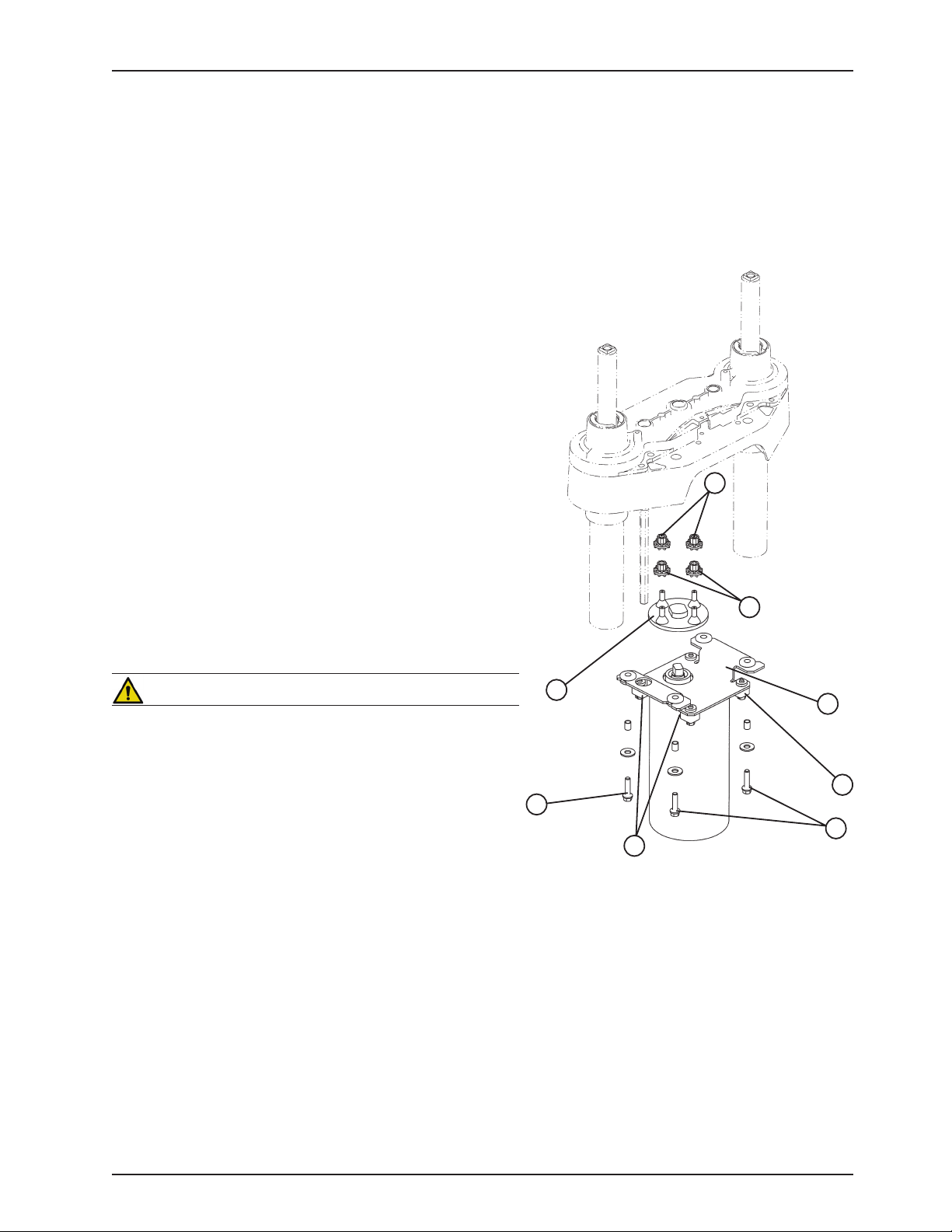
LIFT MOTOR ISOLATION PLATE REPLACEMENT
TOOLS REQUIRED:
7/16” Open End Wrench•
5/16” Nut Driver or 5/16” Socket Wrench•
3/8” Socket Wrench (with 6” ext.)•
PROCEDURE:
Unplug the bed power cord from the wall socket.1.
Using a 5/16” socket wrench, remove the five bolts securing 2.
the lower lift cover and remove the cover.
Using a 3/8” socket with a 6” extension, remove the four bolts 3.
(C) holding the lift motor isolation plate to the lift housing and
carefully lower the isolation plate to the floor.
Remove the motor coupler (A) and bushings (B).4.
Using a 3/8” socket, remove the bolts and washers (E) from 5.
the motor and remove the isolation plate (D).
Reverse the above steps to install the new isolation plate and 6.
reattach all components to the bed.
Note
When reinstalling the lift motor, the drive shaft on the motor will
have to be turned to be aligned with the coupler. Use a 7/16”
open end wrench to turn the drive shaft of the motor.
WARNING
Ensure there is no patient on the bed while the procedure is being
performed.
www.stryker.com 300 6- 009 -102 REV C 35
Return To Table of Contents
Page 36
B
A
C
Service Information
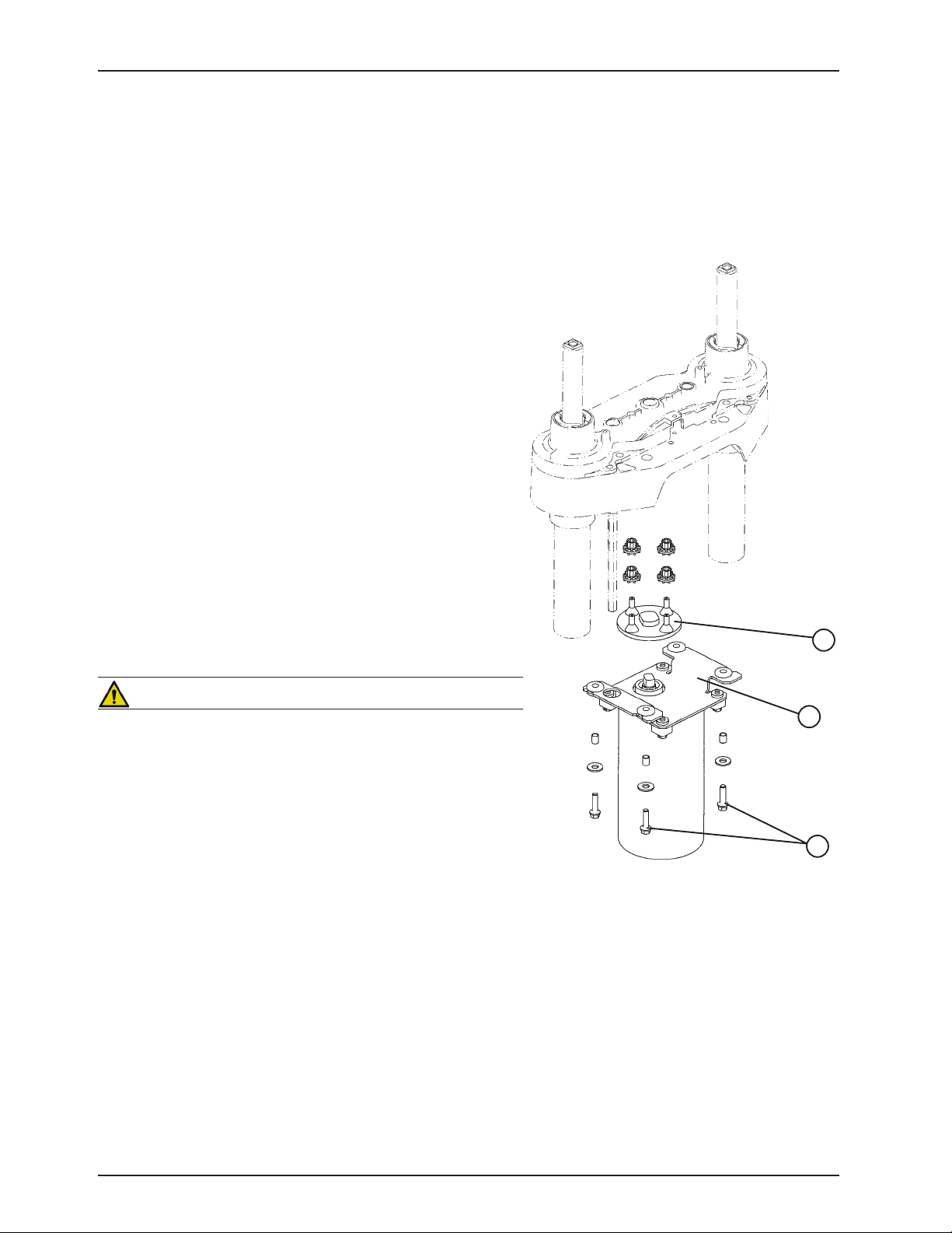
LIFT MOTOR COUPLER REPLACEMENT
TOOLS REQUIRED:
5/16” Socket Wrench•
3/8” Socket Wrench (with 6” Extension)•
Floor Jack•
2x4 (or equivalent)•
PROCEDURE:
Note
If you need more space to work under the base frame, place a 2 x
4 across the base frame rails and use a floor jack to raise the base
frame off the floor.
Unplug the bed power cord from the wall socket.1.
Using a 5/16” socket wrench, remove the five bolts holding the 2.
lower lift cover to the base and remove the cover.
Using a 3/8” socket with an extension, remove the four bolts (A) 3.
holding the isolation plate (B) to the lift housing and lower the
lift motor and isolation plate assembly to allow access to the
coupler (C).
The motor coupler can now be removed from the lift housing.4.
Reverse the above steps to install the new motor coupler and 5.
bushings.
WARNING
Ensure there is no patient on the bed while the replacement
procedure is being performed.
Return To Table of Contents
36 300 6- 009 -102 REV C www.stryker.com
Page 37

Service Information
POWER AND SENSOR COIL CORD REPLACEMENT
TOOLS REQUIRED:
#2 Phillips Screwdriver•
Side Cutters•
5/16” Socket Wrench•
Bungee Cord (or equivalent)•
5/16” Nut Driver•
Floor Jack•
2x4 (or equivalent)•
PROCEDURE:
Note
If you need more space to work under the base frame, place a 2 x 4 across the base frame rails and use a floor jack
to raise the base frame off the floor.
Unplug the bed power cord from the wall socket.1.
Using a 5/16” socket wrench, remove the five bolts holding the lower lift cover to the base and remove the cover.2.
Using a #2 Phillips screwdriver, remove the three screws holding the upper lift cover to the base. If you want, hold 3.
the covers out of the way by using bungee cords (or the equivalent) to secure them to the litter top.
Using side cutters, cut the cable ties holding the power and sensor coil cords to the base. Remove the ground wire 4.
coming from the sensor cord that is attached to the base (note the star washer arrangement).
Disconnect the cables going to the motor and the lift potentiometer (at the head end, the sensor cord is also 5.
attached to the brake switch sensor).
Pull both cords up through the frame of the bed and the lift housing.6.
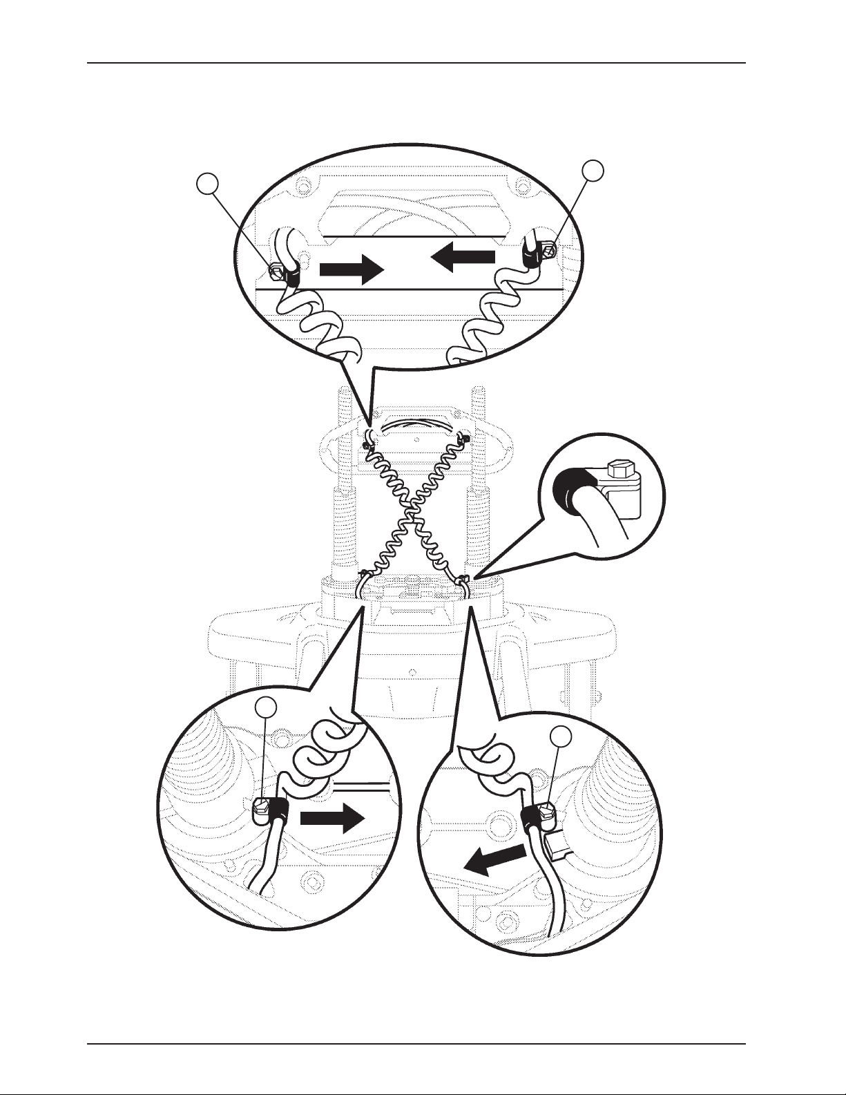
Using a 5/16” socket wrench, remove the two screws (A) holding the cable clamps* to the top of the lif housing.7.
Using a 5/16” socket wrench, remove the two screws (B) securing the cable clamps* to the underside of the 8.
header crossbar assembly.
Pull both coil cords up through the header crossbar assembly.9.
Disconnect the power and sensor coil cords from the connectors.10.
The cords should now be completely removed from the bed. Reverse the above steps to install the new power and 11.
sensor cords.*
CAUTION
* When replacing the power and sensor coil cords, secure the cable clamps to the cords at the first coil both on the
top and on the bottom to ensure there is not too much slack in the cords between the top of the lift housing assembly
and the bottom of the header crossbar. Be sure the clamps are fastened at exactly the correct angle, as shown by the
arrows in the illustration. Arrange the cords exactly as shown in the illustration (left in front of right). If this is not done
correctly, damage to the cords will result.
WARNING
Ensure there is no patient on the bed while the replacement procedure is being performed.
Return To Table of Contents
www.stryker.com 300 6- 009 -102 REV C 37
Page 38
A
B
A
B
Service Information
POWER AND SENSOR COIL CORD REPLACEMENT ILLUSTRATION
View from Center of Bed
Return To Table of Contents
38 300 6- 009 -102 REV C www.stryker.com
Page 39
B
A
C
Service Information
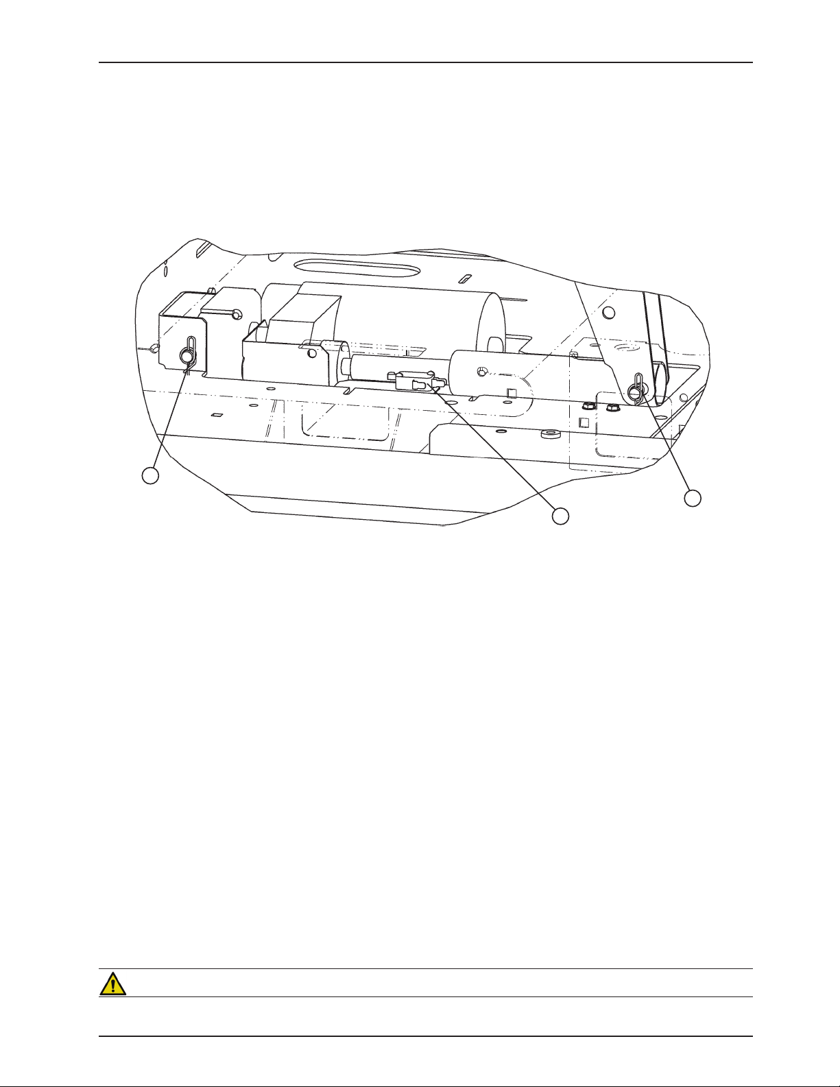
KNEE MOTOR REMOVAL AND REPLACEMENT
TOOLS REQUIRED:
T27 Torx•
Needle Nose Pliers•
3/8” Socket Wrench•
Wire Cutters•
PROCEDURE:
Electrically run the litter fully up. Unplug the bed power cord from the wall receptacle.1.
Using a 3/8” socket wrench, remove the two bolts holding the motion interrupt pan to the litter frame and remove 2.
the pan.
Using needle nose pliers, remove the Rue pin (A) from the end of the drive tube.3.
Fold the Gatch section back toward the head end of the bed. Using a T27 Torx, remove the screw holding the 4.
mid-litter cover to the litter frame and remove the cover.
Remove the two wires from the auto contour micro switch (B) mounted next to the drive tube.5.
Using wire cutters, remove the cable ties. Disconnect the motor and capacitor wires.6.
Using needle nosed pliers, remove the Rue pin (C) from the motor bracket and lift the motor out.7.
Using a 3/8” socket wrench, remove the four bolts holding the motor bracket to the old motor. Remove the bracket 8.
and install it on the replacement motor using the same four bolts.
Install the replacement motor into the bed. Do not hook up the drive tube to the Gatch section yet.9.
Plug the bed power cord into a properly grounded wall receptacle. Using the button on the footboard or siderail, 10.
run the Gatch motor down until it stops.
Reinstall the mid-litter cover.11.
Fold the Gatch section back down. From underneath the bed, manually turn the drive tube in or out until it lines up 12.
with the hole in the Gatch section. Reinstall the pin, the wires for the auto contour switch, and the motion interrupt
pan.
Test the bed for proper operation before returning it to service.13.
WARNING
Ensure there is no patient on the bed while the replacement procedure is being performed.
www.stryker.com 300 6- 009 -102 REV C 39
Return To Table of Contents
Page 40
A
B
C
C
Service Information
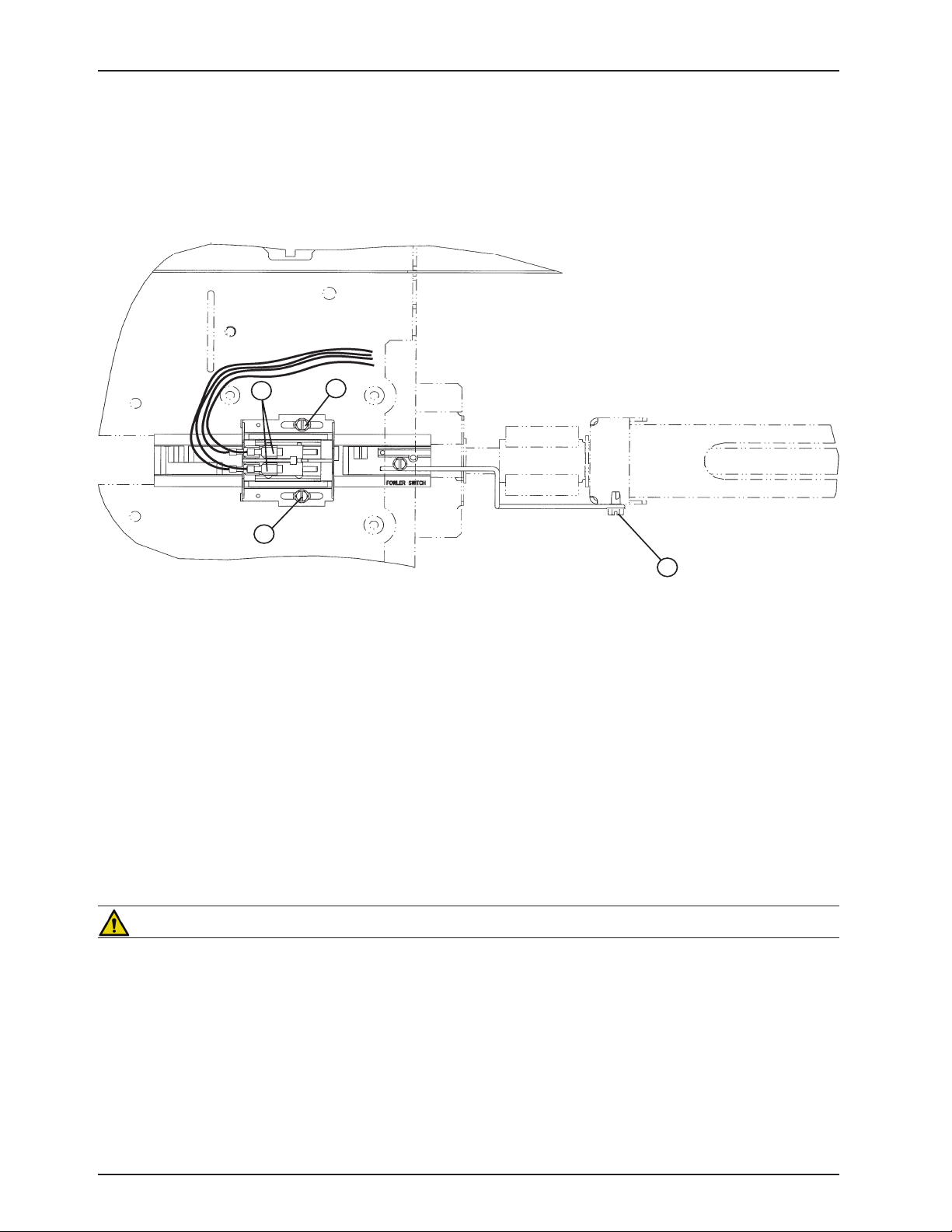
FOWLER MOTOR CAM AND CAM GUIDE REPLACEMENT
TOOLS REQUIRED:
5/16” Nut Driver•
3/8” Socket Wrench•
T27 Torx•
PROCEDURE:
Run the Knee Gatch fully up. Unplug the bed power cord from the wall socket.1.
Using a T27 Torx, remove the screw holding the foot end litter cover to the frame and remove the cover.2.
Using a 3/8” socket wrench, remove the two bolts holding the motion interrupt pan to the litter and remove the 3.
pan.
Using a 5/16” nut driver, remove the screw (A) holding the cam retention wire to the ball nut assembly.4.
Disconnect the cables (B) from the micro-switches. Take note of the locations of the cables so they will be 5.
connected properly to the replacement cam.
Using a 5/16” nut driver, remove the two screws (C) holding the cam and cam guide to the support bracket and 6.
remove the cam and cam guide with the attached micro-switches from the bed.
Reverse the above steps to install the replacement cam and cam guide/micro switch assembly.7.
Refer to “Limit Setting - Fowler Motor” section.8.
WARNING
Ensure there is no patient on the bed while the replacement procedure is being performed.
Return To Table of Contents
40 3006-009-102 REV C www.stryker.com
Page 41
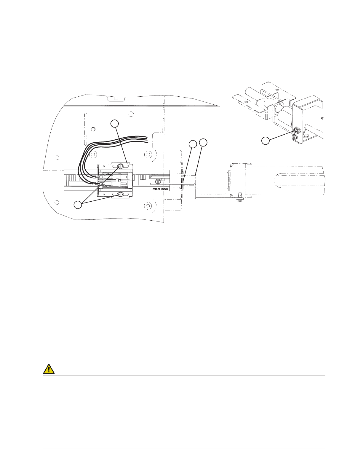
LIMIT SETTING - FOWLER MOTOR
E
B
A
D
C
TOOLS REQUIRED:
5/16” Nut Driver•
T27 Torx•
Service Information
PROCEDURE:
Run the Knee Gatch fully up.1.
Using a T27 Torx, remove the screw holding the midsection litter access covers to the litter and remove the 2.
covers.
Run the head section down electrically until flat (0) or use the CPR release handle to fully lower the head.3.
Lightly tap the Fowler down button until the bolt and bushing (E) are centered in the slot.4.
Unplug the power cord from the wall socket.5.
Using a 5/16” nut driver, loosen the two screws (A) on the cam (B).6.
Slide the cam toward the head of the bed just until the micro-switch is activated (the switch will make a clicking 7.
noise).
Note
Check that the cam “bump” is on the “head” side of the switch actuator.
8. Tighten the two screws (A).
CAUTION
Be sure the head section stops when it is fully up and the ball nut bracket (C) is approximately 3/4” from panel (D). If
not, damage to the unit could result.
Ensure the head section will lower to flat (0) before returning the bed to service. Verify the head section lowers 9.
onto the rubber rests and the motor stops running. Reinstall the litter access panels removed in step 1.
Return To Table of Contents
www.stryker.com 300 6- 009 -102 REV C 41
Page 42
Service Information
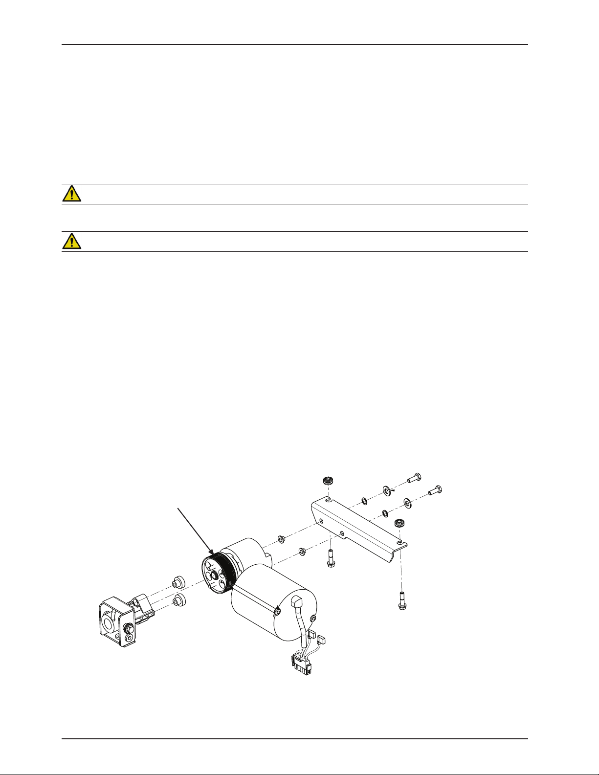
FOWLER MOTOR REMOVAL AND REPLACEMENT
TOOLS REQUIRED:
3/8” Socket Wrench•
PROCEDURE:
WARNING
The head motor is not grounded and may be an electrical hazard. Use caution when working around motors.
CAUTION
Ensure the fowler is lowered all the way down.
Using the CPR release, lower the Fowler to a flat (0 degrees) position.1.
Unplug the bed power cord from the wall socket.2.
Using a 3/8” socket, remove the two bolts at the foot end of the motion interrupt pan and remove the pan.3.
Using a 3/8” socket, remove the two bolts holding the motor bracket to the bed frame. Remove the motor.4.
Note
Use caution when removing the motor to avoid having the coupler come off the ball screw shaft.
Unplug the head motor cables from the bed and capacitor.5.
Prior to installing the new motor assembly, apply a light coat of Syn-Tech grease (p/n 3000-200-700) to the brake 6.
spring.
Reverse the above steps to install the new motor assembly and reattach all litter panels.7.
Apply Syn-Tech grease.
Return To Table of Contents
42 300 6- 009 -102 REV C ww w.stryker.com
Page 43
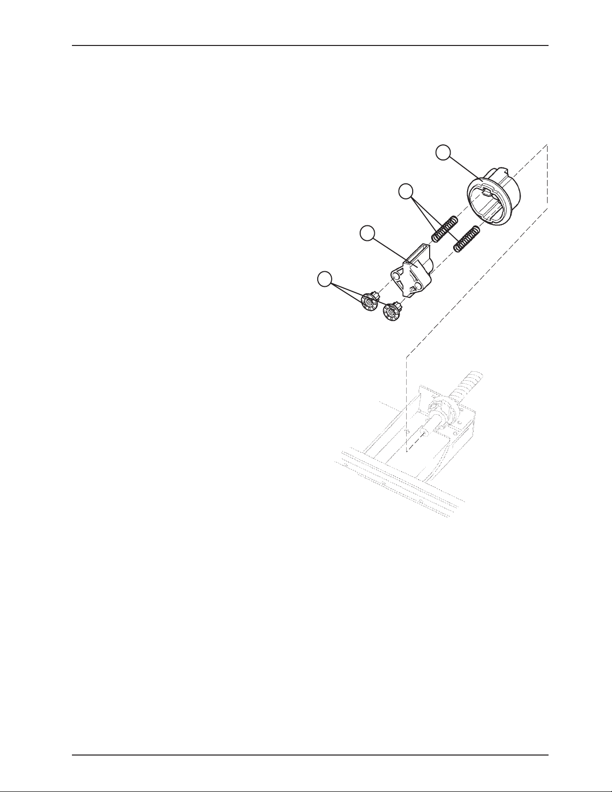
A
B
C
D
Service Information
FOWLER MOTOR DRIVE ISOLATOR AND CPR DECOUPLER REMOVAL AND REPLACEMENT
TOOLS REQUIRED:
3/8” Socket Wrench•
Needle Nose Pliers•
PROCEDURE:
Refer to 1. page 42 “Fowler Motor Removal and
Replacement” procedure to access the isolator,
springs and decoupler.
Pull the drive isolator (C) with the grommets (D), 2.
springs (B) and CPR decoupler (A) off the drive screw
and remove it from the litter.
To reinstall, put the decoupler (A) on the shaft.3.
Using needle nose pliers, bend the end of the springs 4.
(B) out slightly to help hold the springs in the isolator.
Put the springs in the isolator and install it on the
shaft.
Reinstall the fowler motor (5. refer to page 42 “Fowler
Motor Removal and Replacement”).
Run the Fowler up and down several times to test it 6.
before returning the bed to service.
Return To Table of Contents
www.stryker.com 300 6- 009 -102 REV C 43
Page 44
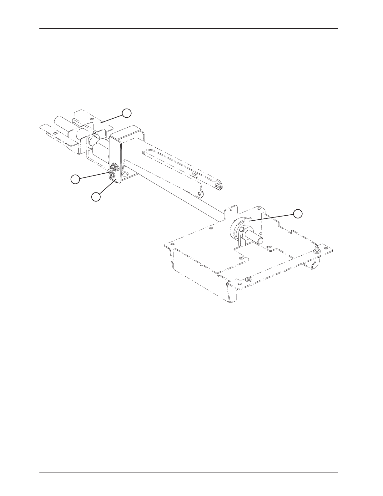
B
A
C
D
Service Information
FOWLER MOTOR BALL SCREW ASSEMBLY REPLACEMENT
TOOLS REQUIRED:
Large Snap-Ring Pliers•
3/8” Socket•
3/8” Ratchet•
Needle-Nose Pliers•
(standard length bed actuator
assembly shown)
PROCEDURE:
Run the bed fully up. Unplug the bed power cord from the wall socket.1.
Using a 3/8” socket, remove the two bolts holding the motion interrupt pan to the litter and remove the pan.2.
Remove the fowler motor (3. refer to page 42 “Fowler Motor Removal and Replacement”) for access to the ball screw
assembly.
Remove the fowler motor drive isolator and CPR decoupler (4. refer to page 43 “Fowler Motor Drive Isolator and CPR
Decoupler Removal and Replacement”).
Using needle nose pliers, remove the cotter pin holding the clevis pin to the drive screw “wing” (A).5.
Remove the clevis pin and slide the wing and tapered roller bearing off the ball screw.6.
Using a 3/8” socket, underneath the litter, remove the screw holding the cam wire link (B) to the ball screw 7.
assembly.
Using a 3/8” socket, remove the two bolts holding the ball screw support bracket (D) to the bottom of the litter and 8.
remove the bracket.
Using large snap ring pliers, remove the snap ring holding the ball screw to the bracket (C).9.
To prevent the ball nut from coming off the drive screw, cable tie both ends of the ball screw.10.
Pull the ball screw toward the foot of the bed and remove the head end of the ball screw assembly from the 11.
support.
Return To Table of Contents
44 3006-009 -102 REV C www.stryker.com
Page 45

Service Information
FOWLER MOTOR BALL SCREW ASSEMBLY REPLACEMENT (CONTINUED)
Note
Do not allow the ball nut assembly to come off the drive screw. The ball nut will be shipped attached to the drive screw
and retained in position during shipment. Remove the wire ties after installing the drive screw assembly.
Remove the thrust washers and bearing from the head end of the drive screw and set them aside.12.
Reverse the above steps to install the replacement ball screw assembly.13.
Note
Apply grease to all bearing areas.
CAUTION
Verify the fowler motor stops properly at both upper and lower electric limits. If it does not, refer to page 41 “Limit
Setting - Fowler Motor”.
HEAD MOTOR BRAKE/CLUTCH REPLACEMENT
TOOLS REQUIRED:
3/8” Socket Wrench•
Snap Ring Pliers•
9/16” Socket Wrench•
9/16” Box End Wrench•
Wire Cutters•
PROCEDURE:
Remove the fowler motor (1. refer to page 42 ”Fowler Motor Removal and Replacement”).
Using snap ring pliers, remove the snap ring from the motor shaft.2.
CAUTION
The brake/clutch is spring-loaded. Use caution when removing the snap ring so the parts do not drop to the floor.
Remove the old brake/clutch from the motor and discard it.3.
Using a 9/16” socket wrench and a 9/16” box end wrench, remove the nut, bolt and washers from the new 4.
brake/clutch.
Install the new brake/clutch onto the motor. It may be necessary to turn the motor shaft to line up the key way with 5.
the brake/clutch.
Using the snap ring pliers, install the new snap ring.6.
Using the wire cutters, remove the four wire ties from the new brake/clutch.7.
Reinstall the fowler motor (8. refer to page 42 “Fowler Motor Removal and Replacement”)
Test the bed for proper operation before returning it to service.9.
Return To Table of Contents
www.stryker.com 300 6- 009 -102 REV C 45
Page 46
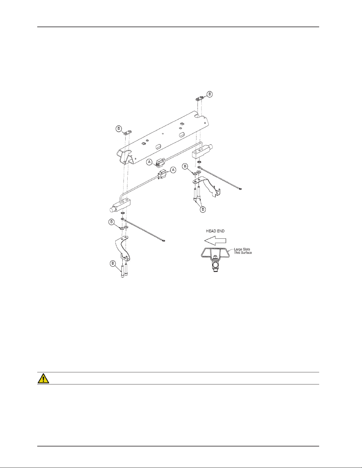
LOAD CELL REPLACEMENT
TOOLS REQUIRED:
1/4” Hex Allen Wrench•
Wire Cutters•
Service Information
PROCEDURE:
Unplug the bed power cord from the wall socket.1.
Support the corner of the litter where the load cell is being removed.2.
Unplug the load cell connector (A) from the load cell cable. Using the side cutters, cut the cable ties.3.
Using a 1/4” hex Allen wrench, remove the screws, washers, and nuts (B) holding the load cell to the bed.4.
To remove a load cell at the head end of the bed, slide the load cell toward the center of the bed to clear the 5.
bushing that supports the load cell. Remove the load cell by lifting it up and out. To remove a load cell at the foot
end of the bed, slide the load cell with the roller bushing toward the center of the bed to clear the litter frame.
Remove the load cell and the roller bushing by lifting them up and out.
Reverse the above procedure to install the new load cell.6.
CAUTION
Be sure the load cell’s strain gauge is facing up when installing a new load cell or the weigh system will not work
properly.
Recalibrate the weigh system (7. refer to page 61 “Calibrate Scale”).
Return To Table of Contents
46 3006-009-102 REV C www.stryker.com
Page 47
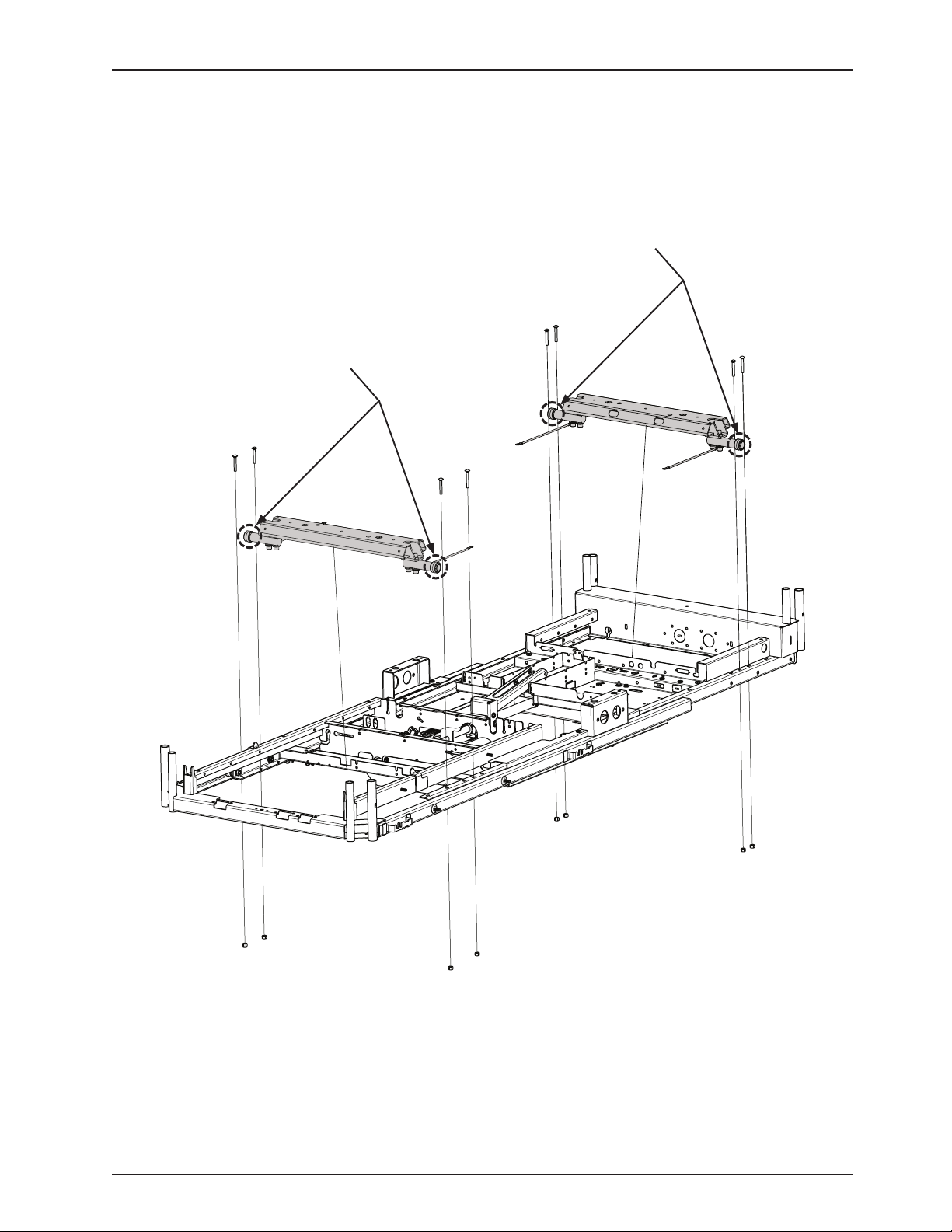
Service Information
LOAD CELL REPLACEMENT - GREASE POINTS
Apply Syn-Tech NS-18191-G grease to rollers on the Lift Header Assembly as shown in figure below.1.
Rollers
Rollers
LIFT H EADER ASSE MBLY
LIFT H EADER ASSE MBLY
Litter Assembly (Reference p/n: 3006-300-197)
Return To Table of Contents
www.stryker.com 300 6- 009 -102 REV C 47
Page 48

Service Information
POWER SUPPLY REPLACEMENT
TOOLS REQUIRED:
#2 Phillips Screwdriver•
T27 Torx•
PROCEDURE:
Adjust the Fowler to approximately 25-30. Unplug the bed power cord from the wall socket.1.
Properly ground yourself (2. refer to page 14 “Static Discharge Precautions”).
Using a T27 Torx, remove the two screws holding the head end litter access cover and remove the cover.3.
Disconnect all cables at the power supply. Note the locations of the cables so they will be reconnected properly 4.
to the replacement power board.
To remove the board from the litter standoffs, use a #2 Phillips screwdriver to remove the four screws holding the 5.
board to the litter. Remove the board.
Install the new board and reconnect all cables.6.
Reinstall the litter access panel and plug the bed power cord into a properly grounded wall receptacle.7.
Test the bed for accurate operation before returning it to service.8.
CPU BOARD REPLACEMENT
TOOLS REQUIRED:
T27 Torx Driver •
PROCEDURE:
Adjust the Fowler to approximately 25-30. Unplug the bed power cord from the wall socket.1.
Properly ground yourself (see “Static Discharge Precautions” section).2.
Using a T27 Torx, remove the two screws holding the head end litter access cover and remove the cover.3.
Disconnect all cables at the litter CPU board. Note the locations of the cables so they will be connected properly 4.
to the replacement litter CPU.
To remove the board from the litter standoffs, pull out on the retention clips and lift upward on the board.5.
Install the new board and reconnect all cables.6.
Reinstall the litter access panel and plug the bed power cord into a properly grounded wall receptacle.7.
Before installing new CPU, mirror the dip switch settings (SB1, SB2, SB3 and SB4) of the old CPU to the new CPU 8.
(see “CPU Board - 3006-307-900” section).
When a new CPU board is installed, the following procedures must be executed:9.
a. Software Configuration procedures on page 4.
b. Lift Potentiometer “Burn-In” procedures on page ???.
If your Bed is equipped with a Scale System, execute the Scale Calibration procedures on 10. page 61. Test bed
operations before returning the bed to service.
Return To Table of Contents
48 3006 -0 09-102 REV C www.stryker.com
Page 49
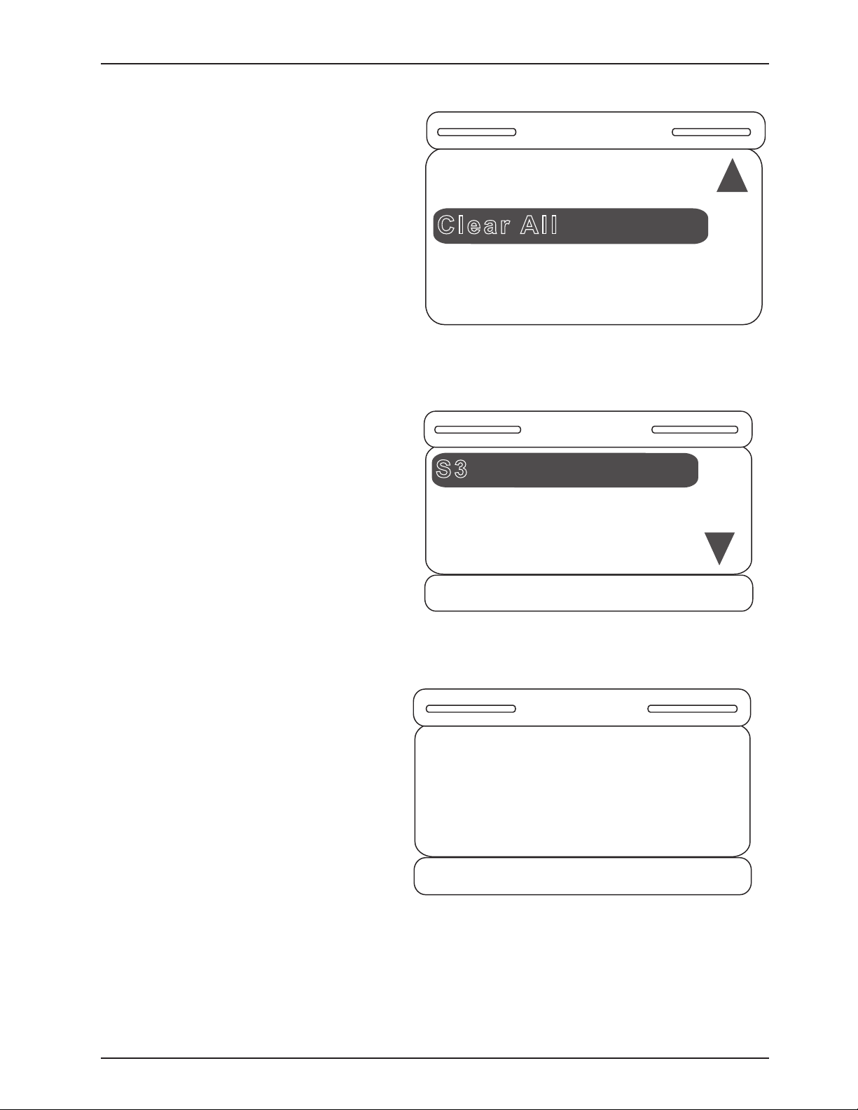
Service Information
Clear All
Bed Config.
Bed Type
S3
Bed Type
Secure
= Save
X = Cancel
Epic
Set Bed Type to
S3?
= Accept
X = Cancel
Message
SOFT CONFIG. PROCEDURES
1. On the first power up, the footboard screen
will display Figure S-1. Only two items should be
displayed.
2. Once the user selects the Bed Type item and
hits “Enter” on the footboard panel, Figure S-2 will
be displayed. To select an item hit “Enter” on the
footboard panel. Choose S3.
Figure S-1
3. Once a bed type has been selected from the list
above, a confirmation screen such as that in Figure
S-3 will be displayed, asking the user a question.
(The confirmation screen text will vary based on
the item selected. Figure S-3 indicates that the
user chose the bed type S3.) Hit “Enter” on the
footboard panel to confirm the bed type; hit “Exit”
to cancel the operation.
Figure S-2
Figure S-3
www.stryker.com 300 6- 009 -102 REV C 49
Return To Table of Contents
Page 50
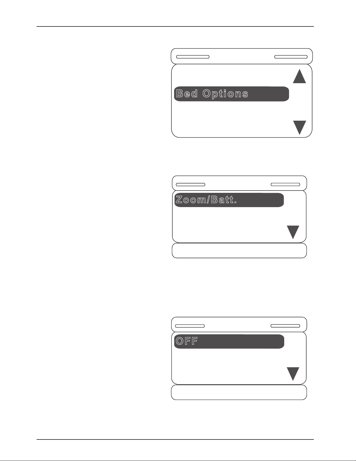
Service Information
Bed Options
Bed Config.
Bed Type [S3]
Clear All
Zoom/Batt.
Bed Options
Scale
= Enter
X = Exit
Bed Exit
OFF
Zoom/Batt.
Zoom
= Save
X = Cancel
Batt.
SOFT CONFIG. PROCEDURES (CONTINUED)
4. Once the bed type is selected, the Bed Options
item becomes available. Note that you can also
see the Bed type that you’ve previously selected.
Hit “Enter” on the footboard panel to choose the
options for the product.
5. Once the Bed Option item is selected, the menu
in Figure S-5 will be displayed on the screen. Each
option must be set to OFF, ON or a variety of the
option (i.e., Zoom/Batt. or Bed Exit). Configure each
option in the order presented on the screen (i.e.,
set the Zoom/Batt option before the Scale option,
which should be set before the Bed Exit option,
which should be set before the Awareness option).
Figure S-4
6. Once the Zoom/Batt. option is selected, Figure
S-6 will be displayed. You can set this option to
OFF, Zoom or Battery Backup. Scroll up or down
to select one of the three available items and hit
“Enter” on the footboard panel.
Return To Table of Contents
50 300 6- 009 -102 REV C www.stryker.com
Figure S-5
Figure S-6
Page 51
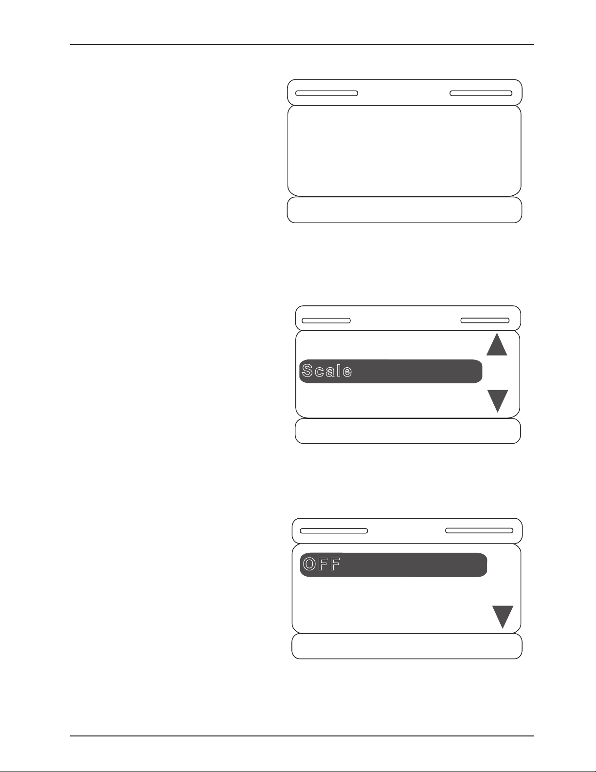
Service Information
Set Bed Option
Zoom/Batt to Zoom?
= Accept
X = Cancel
Message
Scale
Bed Options
Zoom/Batt. [Zoom]
= Enter
X = Exit
Bed Exit
Scale
= Save
X = Cancel
OFF
ON
SOFT CONFIG. PROCEDURES (CONTINUED)
7. Once you have selected one of the items, a
confirmation screen such as that in Figure S-7
will be displayed. The confirmation screen text
will vary based on the item you have selected.
The confirmation screen displayed in Figure S-7
indicates that the user chose Zoom. Hit “Enter”
on the footboard panel to confirm the Zoom/Batt.
option; hit “Exit” to cancel the operation.
Figure S-7
8. Once the Zoom/Batt. option is set, you will return
to the Bed Options screen and the next item to be
set will be highlighted. Note that you can also see
what the previous option was set to.
9. Once the Scale item is selected, the screen in
Figure S-9 will be displayed. You can set the Scale
option to ON or OFF. Hit “Enter” on the footboard
panel to make your selection or hit “Exit” to
cancel.
Figure S-8
www.stryker.com 300 6- 009 -102 REV C 51
Figure S-9
Return To Table of Contents
Page 52
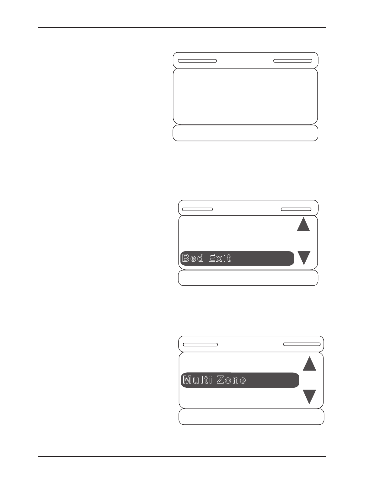
Service Information
Set Bed Option
Scale to ON?
= Accept
X = Cancel
Message
Bed Exit
Bed Options
Zoom/Batt. [Zoom]
= Enter
X = Exit
Scale [ON]
Multi Zone
Bed Exit
OFF
Single Zone
= Save
X = Cancel
SOFT CONFIG. PROCEDURES (CONTINUED)
10. Once you have selected one of the items,
a confirmation screen will be displayed. The
confirmation screen text will vary based on the
item you have selected. The confirmation screen
in Figure S-10 indicates that the Scale option was
chosen to be ON. Hit “Enter” on the footboard panel
to confirm your Scale option; hit “Exit” to cancel the
operation.
Figure S-10
11. Once the Scale option is set, you will be returned
to the Bed Options screen to set the next option,
which is Bed Exit.
12. Once the Bed Exit item is selected, the screen
in Figure S-12 will be displayed. You can set the
Bed Exit Option to OFF, Multi Zone or Single Zone.
Hit “Enter” on the footboard panel to make your
selection or “Exit” to cancel.
Figure S-11
Return To Table of Contents
52 30 06- 009 -102 REV C www.stryker.com
Figure S-12
Page 53
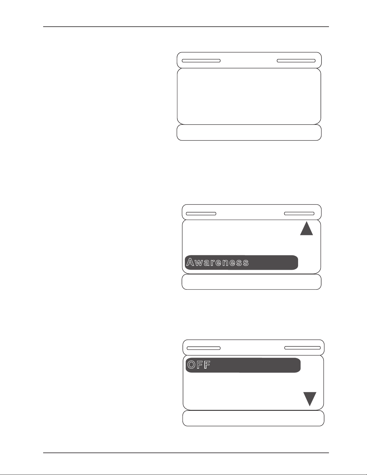
Service Information
Set Bed Option Bed
Exit to Multi Zone?
= Accept
X = Cancel
Message
Awareness
Bed Options
Scale [ON]
= Enter
X = Exit
Bed Exit [Multi]
OFF
Awareness
ON
= Save
X = Cancel
SOFT CONFIG. PROCEDURES (CONTINUED)
13. Once you have selected one of the items, a
confirmation screen such as that in Figure S-13
will be displayed. The confirmation screen text will
vary based on the item you have selected. The
confirmation screen in Figure S-13 indicates that
the user chose the Bed Exit option to be Multi Zone.
Hit “Enter” on the footboard panel to confirm your
Bed Exit option; hit “Exit” to cancel the operation.
Figure S-13
14. Once the Bed Exit option is set, you will be
returned to the Bed Options screen to set the next
option, which is Awareness. Note that you can see
the state of each option that you have previously
set.
15. Once the Awareness item is selected, the
screen in Figure S-15 will be displayed. You can set
the Awareness option to OFF or ON. Hit “Enter” on
the footboard panel to make your selection or “Exit”
to cancel. Note that if Bed Exit was set to OFF,
Awareness will then automatically be set to OFF
as well. It cannot be set to ON unless either kind
of Bed Exit was previously chosen.
Figure S-14
www.stryker.com 300 6- 009 -102 REV C 53
Figure S-15
Return To Table of Contents
Page 54
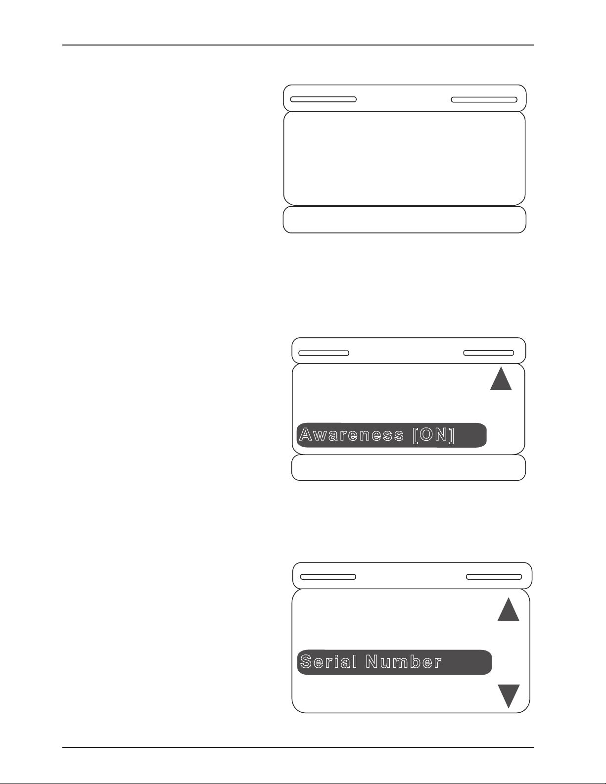
Service Information
Message
= Accept
X = Cancel
Set Bed Option
Awareness to ON?
Awareness [ON]
Bed Options
Scale [ON]
= Enter
X = Exit
Bed Exit [Multi]
Serial Number
Bed Config.
Bed Type [S3]
Bed Options [SET]
Clear All
SOFT CONFIG. PROCEDURES (CONTINUED)
16. Once you have selected one of the items, a
confirmation screen such as that in Figure S-16
will be displayed. The confirmation screen text
will vary based on the item you have selected.
The confirmation screen in Figure S-16 indicates
that the user chose the Awareness option to be
ON. Hit “Enter” on the footboard panel to confirm
your Awareness option; hit “Exit” to cancel the
operation.
Figure S-16
17. Once the Awareness option is set, you will be
returned to the Bed Options screen as shown in
Figure S-17. Once there is text in square brackets
next to each option in the Bed Options menu, all of
your options have been set. You may re-enter any
option and change the setting at any time.
18. Hitting “Exit” on the footboard panel while in
the Bed Options screen will return the user to the
Bed Config. main menu as shown in Figure S-18.
Note that the user can see the state of the items
previously set.
Figure S-17
Return To Table of Contents
54 3006- 009 -102 REV C www.stryker.com
Figure S-18
Page 55
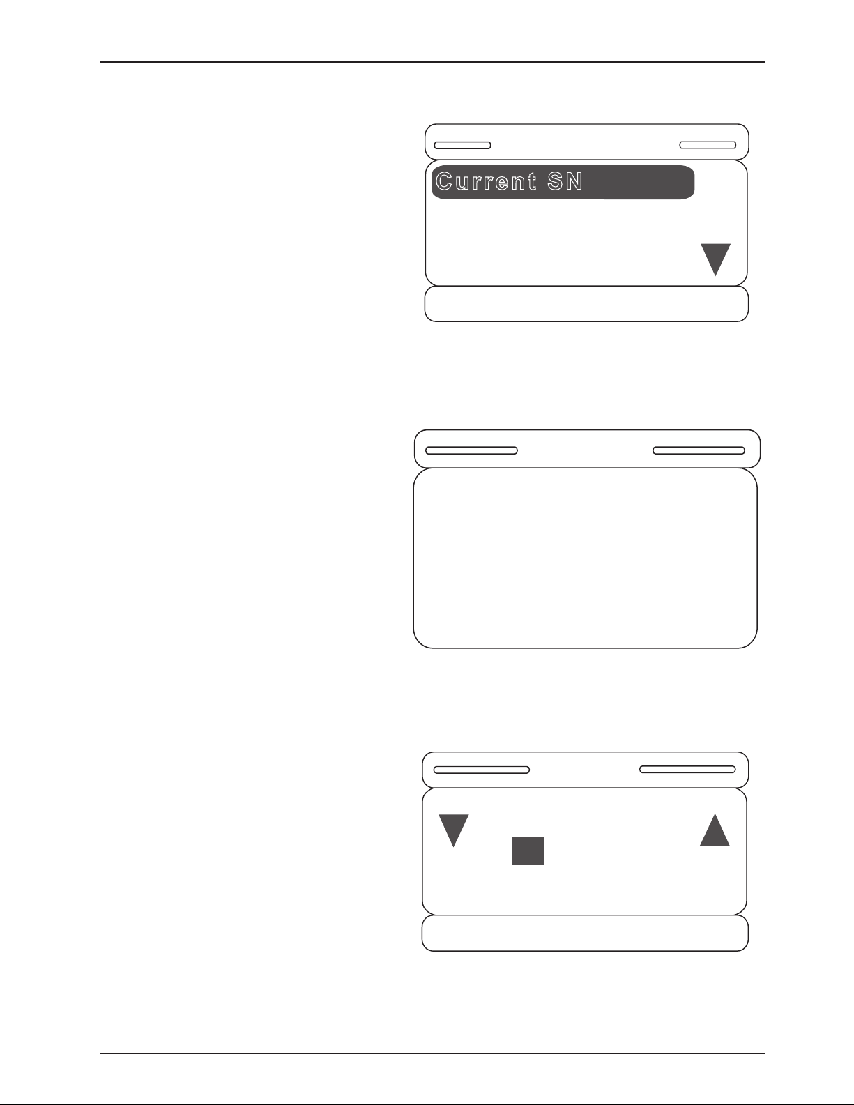
Service Information
Current SN
Serial Number
Edit SN
= Enter
X = Exit
Message
Serial Number Not
Set
Edit SN
= Save
X = Cancel
+
-
080115000
SOFT CONFIG. PROCEDURES (CONTINUED)
19. There are two options available, as shown in
Figure S-19. The Current SN item will display the
saved serial number, while the Edit SN item will
allow the user to edit the existing serial number.
20. If the Current SN item is selected and no
serial number has been entered by the user,
the screen in Figure S-20 will be displayed.
Figure S-19
21. If the Edit SN item is selected, the screen
in Figure S-21 will be displayed to the user.
www.stryker.com 300 6- 009 -102 REV C 55
Figure S-20
Figure S-21
Return To Table of Contents
Page 56
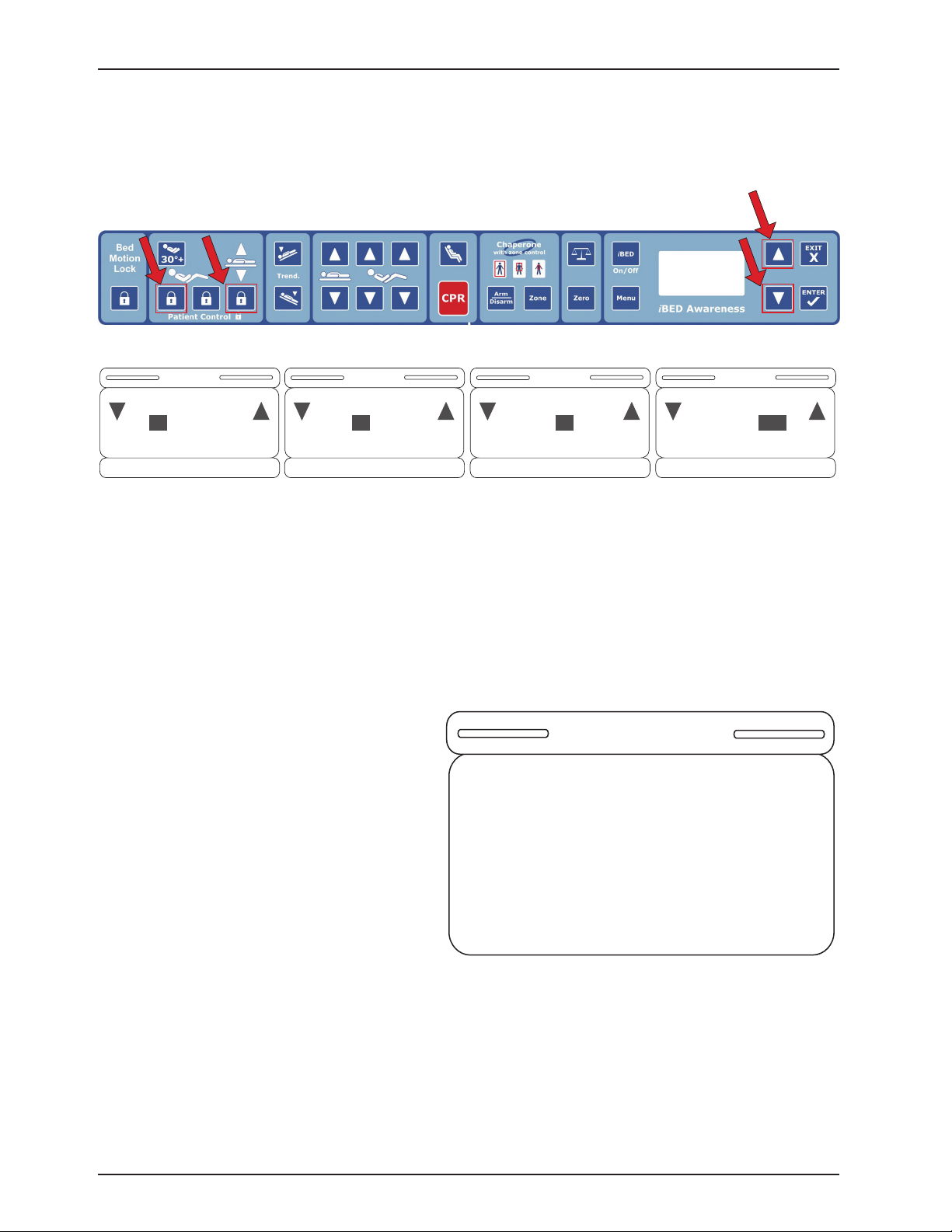
Service Information
Edit SN
= Save
X = Cancel
+
-
080115000
Edit SN
= Save
X = Cancel
+
-
080115000
Edit SN
= Save
X = Cancel
+
-
080115000
Edit SN
= Save
X = Cancel
+
-
080115000
Current SN
080115000
SOFT CONFIG. PROCEDURES (CONTINUED)
22. Use the two blinking lock buttons to select the desired portion of the serial number. This selected portion will
remain highlighted. Then use the footboard panel up/down buttons to edit the serial number.
Footboard Panel
Lock Buttons
Up/Down Buttons
Figure S-22
23. Once the bed up/down lock key is pressed, the highlighted sections will change as indicated above in Figures S-22,
23, 24 and 25. Hold down “Enter” on the footboard panel for two seconds to save the serial number or press “Exit” to
cancel the operation.
24. Once a serial number is saved and the user
enters the Current SN item, the screen in Figure
S-26 will be displayed. The entered serial number
will be displayed until the user hits the “Exit” button
on the footboard panel.
Figure S-23 Figure S-25Figure S-24
Return To Table of Contents
56 300 6- 009 -102 REV C ww w.stryker.com
Figure S-26
Page 57
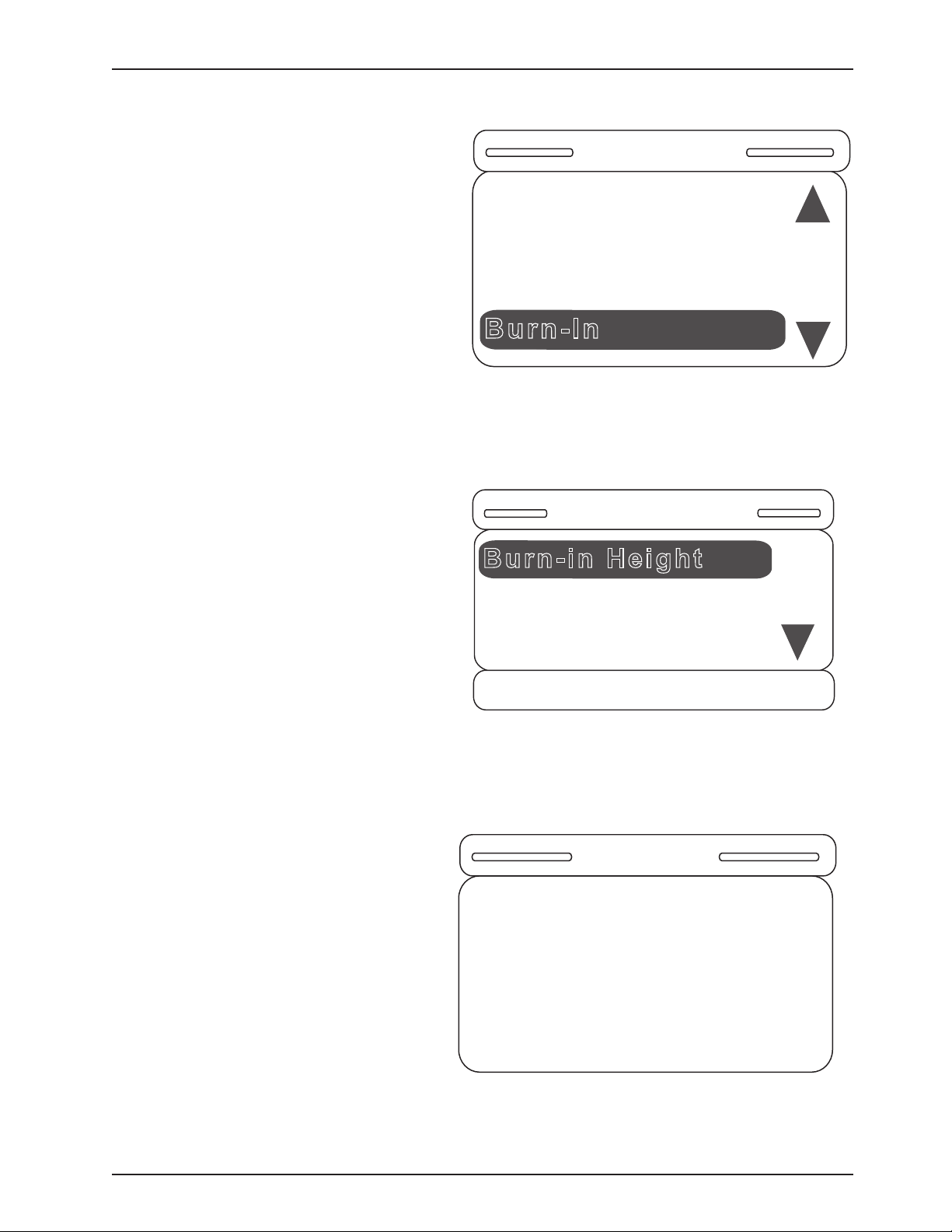
Service Information
Burn-In
Bed Config.
Bed Type [S3]
Bed Options [SET]
Serial Number [SET]
Burn-in Height
Burn-In Limits
Burn-in Fowler
= Enter
X = Exit
Message
Put Bed in High Height
SOFT CONFIG. PROCEDURES (CONTINUED)
25. Hitting “Exit” on the footboard panel while in
the Serial Number screen will return the user to the
Bed Config main menu as shown in Figure S-27.
Note that the user can see the state of the items
previously set.
Figure S-27
26. Once the Burn-in item is selected, the screen
in Figure S-28 will be displayed. The Burn-in Height
item will walk the user through the burn-in height
routine; and, similarly, the Burn-In Fowler item will
walk the user through the burn-in fowler routine.
27. The burn-in height routine will display different
messages depending on if the user chooses to
activate the Zoom/Batt. option. If the Zoom or
Battery Backup option is activated, the message
in Figure S-29 will be shown on the screen. If the
Zoom/Battery Backup option was deactivated, then
the message would display: “Put Bed in Low Height.”
Drive the bed to its high or low height (depending
on the message displayed) and hold the Bed Motion
Lock. The screen will display the message “Hold to
Set Height Limits.” Once the lock button is held for
two seconds, the message “Release Button” will
flash.
Figure S-28
Figure S-29
www.stryker.com 300 6- 009 -102 REV C 57
Return To Table of Contents
Page 58
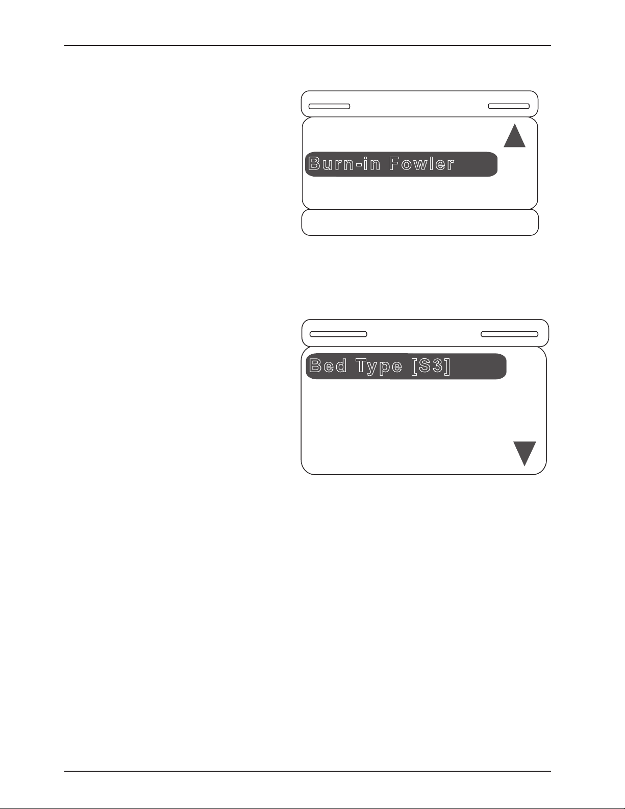
Service Information
Burn-in Fowler
Burn-In Limits
Height Limits [SET]
= Enter
X = Exit
Bed Type [S3]
Bed Config.
Burn-in [SET]
Bed Options [SET]
Serial Number [SET]
SOFT CONFIG. PROCEDURES (CONTINUED)
28. Once the lock button is released, the message
“Height Limit Set” will be displayed and the user will
be returned to the screen in Figure S-30 (The height
limits are now burned in.) The “SET” text indicates
that the limits are set. The process is similar for the
Burn-in Fowler routine.
Once the Burn-in Fowler item is selected, the
message “Set Fowler to Lower Limit” is displayed.
Press and hold the “Enter” button to set the lower
limit. The message “Set Fowler to 300” will now be
displayed. Once this is completed, the message
“Set Fowler to Upper Limit” will be dislpayed.
Once all three limits are burned in, the message
“Fowler Calibration Complete” will be displayed for
two seconds and the user will be returned to the
Bed Config. menu.
29. Once all Bed Config. items are set, the main
screen will be displayed as in Figure S-31.
Figure S-30
30. Good to note:
Any item may be adjusted at any time.•
If the Bed Type is changed, the serial number and burn-in limits are cleared and the process needs to be repeated •
by the user.
If the Zoom options are changed, the burn-in limits are cleared and the process needs to be repeated by the •
user.
The user must cycle power to the bed to exit the Bed Config. mode. •
The user will not be able to exit the Bed Config. mode without setting all items (with the exception of the fowler •
limits). I.E., the user must choose the Bed Type, set all options to either ON, OFF or some variety of the option,
enter the serial number and burn-in the height limits in order to exit the Bed Config. menu on a power cycle.
Return To Table of Contents
58 300 6- 009 -102 REV C www.stryker.com
Figure S-31
Page 59
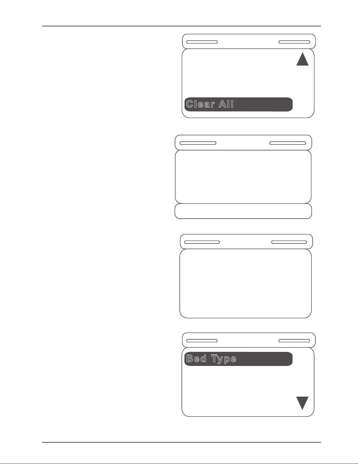
Service Information
Clear All
Bed Config.
Bed Options [SET]
Serial Number [SET]
Burn-in [SET]
Clear All Config.
Items?
= Accept
X = Cancel
Message
Message
Bed Config. Cleared
Bed Type
Bed Config.
SOFT CONFIG. PROCEDURES (CONTINUED)
30. Good to Note (Continued)
To quickly clear all entered Bed Config. items, •
there is a Clear All item which will always be
the last item in the Bed Config. menu.
Once the “Clear All” item is selected, the •
confirmation screen in Figure S-33 will be
displayed.
Figure S-32
Once the user hits “Enter,” the previously set •
Bed Config. items (Bed Type, Bed Options,
Serial Number, Height Limits or Fowler Limits)
will be erased and the message in Figure S-34
will be displayed.
The Bed Config. menu will then only display •
the Bed Type menu item as shown in Figure
S-35 and the user can now re-enter all the bed
information starting with the Bed Type.
Figure S-33
Figure S-34
www.stryker.com 300 6- 009 -102 REV C 59
Figure S-35
Return To Table of Contents
Page 60

Service Information
MAINTENANCE MENU SCREEN
The Maintenance Menu contains all of the non-regularly accessible features of the product. This menu provides
an interface to the user and/or service personnel in order to provide the ability to control and access maintenance
features.
Maintenance Menu Items
The following are menu items listed in the maintenance menu screen for a fully loaded bed:
Calib. Scale (Calibrate Scale)1.
TV Config. (TV Configuration)2.
Scale Info. (Scale Info/Stats)3.
Clear Scale Stats4.
Error Log (View Error Log) 5.
Clear Errors (Clear Error Log)6.
Scale Units (Lock Scale Units)7.
About (About Product)8.
Exit Menu (Exit Maintenance)9.
The following are menu items listed in the maintenance menu screen for a standard bed:
TV Config. (TV Configuration)1.
Error Log (View Error Log)2.
Clear Errors (Clear Error Log)3.
About (About Product)4.
Exit Menu (Exit Maintenance)5.
The following are menu items listed in the maintenance menu screen for an iBed:
Calib. Scale (Calibrate Scale)1.
TV Config. (TV Configuration)2.
Scale Info. (Scale Info/Stats)3.
Clear Scale Stats (only if you have scale option)4.
Error Log (View Error Log) 5.
Clear Errors (Clear Error Log)6.
Scale Units (Lock Scale Units)7.
About (About Product)8.
Exit Menu (Exit Maintenance)9.
Each of the menu items provides the operator with a different function. •
Using the up and down menu buttons, you can scroll though the menu elements. •
To select a menu item, scroll to the desired menu item using the Up and Down menu button. When the desired •
feature is highlighted, press the Enter/Check button. Depending on the feature, the display will move into the
sequence for the feature selected.
Load Cell Check (Where applicable: for beds with a minimum of Scale or either kind of Bed Exit)
This feature automatically checks all four load cells to make sure they are working properly.•
The purpose of this feature is to provide a self diagnostic of the load cells.•
When maintenance is entered, a self-diagnostic feature should run and display results.•
While the procedure is running, the following message is displayed: “Load Cell Check”.•
Any load cell errors will be displayed as a message “Load Cell Error” and then, depending on the error, an HL, •
HR, FL or FR will be displayed below the message. (Refer to the Error Handling Section).
If no errors are present, then the maintenance menu will be displayed and menu items 1-9 above may be •
accessed where applicable.
Return To Table of Contents
60 3006-009-102 REV C www.stryker.com
Page 61

Maintenance Menu (Continued)
Calibrate Scale
This feature allows the operator to calibrate the scale system. •
This calibration is used to provide the system with a weight offset that occurs when the product is put into •
trend and reverse trend.
This calibration does not calibrate the load cells; the load cells are pre-calibrated. •
To calibrate the scale system:
In the Maintenance Menu, select the Calibrate Scale item; then press and hold the Enter/Check button.1.
The display should present the following message: 2.
“Do Not Touch Bed”. The message should be flashing.
Use the up and down arrow to select the proper weight (50lbs is the default).3.
Press the “Enter/Check” button when the display shows the proper weight.4.
The display should present the following message: 5.
“Place Weight in Center”.
Place the weight in the center of the bed.6.
Press the “Enter/Check” button when completed.7.
The display should present the following message: 8.
“Press Reverse Trend”.
Press the reverse trend button.9.
The display should present the following message when the bed is in the proper position: 10.
“Release Button”.
Release the button and do not touch the bed. When the button is released, the following message is displayed: 11.
“Do Not Touch Bed”. The message should be flashing.
The display should present the following message when the bed is ready to continue: 12.
“Press Trend”.
Press the trend button.13.
The display should present the following message when the bed in the proper position: 14.
“Release Button”.
Release the button and do not touch the bed. When the button is released the following message is displayed: 15.
“Do Not Touch Bed”. The message should be flashing.
The display should present the following message when the bed is ready to continue: 16.
“Save Calibration?”.
Press the “Enter/Check” button to save the calibration.17.
The display should present the following message when the bed is ready to continue: 18.
“Save Successful”.
Service Information
Note:
If an error occurs during the procedure the display will show an error message, “Calibration Error,” for four
seconds.
WARNING
Ensure there is no patient on the bed while the calibration procedure is being performed.
Return To Table of Contents
www.stryker.com 300 6- 009 -102 REV C 61
Page 62
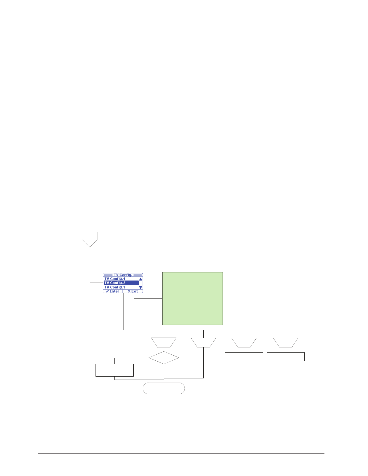
Maintenance Menu (Continued)
TV
Config
Note: The user will use the arrow buttons to select the option. The selected item on
initialization will be the item that is currently set. If the user presses the ‘Enter’ button
then the new setting will be saved. If the user presses the ‘Exit’ button or the menu
times out (30 seconds after last button press) then the old setting will remain and the
screen will return to the ‘Maintenance menu’.
Accept Cancel
Arrow
Up
Arrow
Down
Scroll Display Selected
Item Up One item.
Scroll Display Selected
Item Down One item.
Display = “Save
Successful” (Hold
message for 2 seconds)
Is ‘New’ SettingYes
No
Return to Maintenance
Menu
TV Config. 1
TV Config. 2
TV Config. 3
TV Config. 4
TV Config. 5
TV Config. 6
Traditional
Traditional Plus
Auto-Config.
Auto-Config. DV
Menu Items
TV Configuration
This feature allows the operator to set up the TV configuration. •
This configuration provides the product with the information to communicate with the proper entertainment •
system.
To Configure the System:
In the Maintenance Menu, select the TV Config. item; then press and hold the Enter/Check button.1.
The TV Configuration Screen will be displayed. The current TV selection will be highlighted.2.
Use the up and down arrow buttons to highlight the desired item.3.
Press the “Enter/Check” button to select the new setting. 4.
The following message will be shown on the display screen when the new setting is saved: 5.
“Save Successful”.
The TV Configuration screen should reappear after two seconds and the new setting should be highlighted.6.
If you press the Exit/X button or if the screen remains dormant for more than 30 seconds, the display will 7.
return you to the maintenance menu without saving any changes.
Service Information
Return To Table of Contents
62 3006- 009 -102 REV C ww w.stryker.com
Page 63
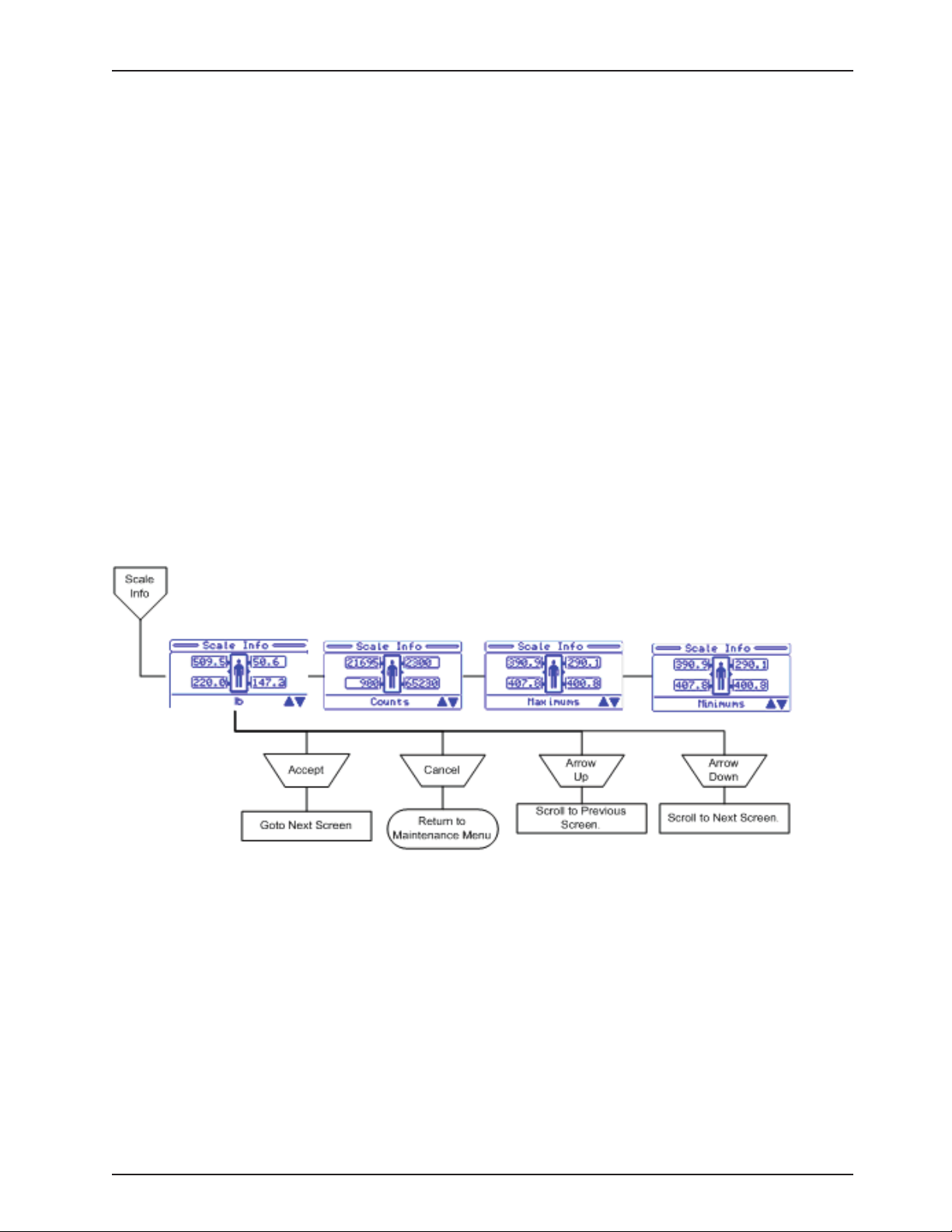
Service Information
Maintenance Menu (Continued)
Scale Information
This diagnostic feature shows data from the load cells. This includes the raw count data, the weight data (in •
lb), the maximums and the minimums.
When the menu item is selected, the weight data from the four load cells will be displayed. •
When cancel/exit is pressed, the menu should return.•
Values should update every 0.25 seconds.•
Note: The scale information and statistics are important when trying to diagnose the scale system.
To View the Scale Information:
In the Maintenance Menu select the Scale Info item; then press and hold the Enter/Check button.1.
The Scale Info screen will be displayed.2.
Use the arrows to navigate through the four screens: lb, counts, maximums, and minimums. Each screen will 3.
have the four load cells and the information in the format of that screen.
Press the Exit/X button to return to the Maintenance Menu screen.4.
Clear Scale Stats
This diagnostic feature allows the statistics for the load cells to be cleared.•
This is done to remove old data. This may be done because the load cell is being replaced or the system has •
been re-calibrated.
When the menu item is selected and held for one second, the statistics should be erased and a message •
should be displayed. When cancel/exit is pressed, the menu should return to the Maintenance Menu Screen.
Note: The scale statistics (Maximums and Minimums) can be cleared using this feature.
To Clear the Information:
In the Maintenance Menu, select the Clear Scale Stats item; then press and hold the Enter/Check button.1.
The following message will be shown on the display screen: 2.
“Clear Scale Statistics?”
Return To Table of Contents
www.stryker.com 300 6- 009 -102 REV C 63
Page 64

Service Information
Maintenance Menu (Continued)
Press and hold the Enter/Check button to clear the stats.3.
The following message will be shown on the display screen when the stats are cleared: 4.
“Statistics Cleared”.
The Maintenance Menu screen should reappear after two seconds 5.
and the new setting should be highlighted.
Note: Items that are cleared during this operation are:
Maximums (for each load cell)•
Minimums (for each load cell)•
Error Log
This feature allows the operator to view the Error Log.•
This log provides information pertaining to the error system and any errors that are logged during product •
use.
To view the error log:
In the Maintenance Menu, select the Error Log item; then press the Enter/Check button.1.
The Error Log screen will be displayed. The most recent error will be at the top.2.
Use the up and down arrow buttons to view any errors that are not shown on the screen. 3.
Pressing the Exit/X button will return you to the Maintenance Menu screen.4.
If the screen remains dormant for more than 30 seconds, you will be returned to the Maintenance Menu 5.
screen.
Clear Errors
This feature allows the user to clear the error log.
To clear the error log:
In the Maintenance Menu, select the Clear Errors item; then press and hold the Enter/Check button.1.
The following confirmation screen will be displayed: 2.
“Clear Error Log?”
If ‘Exit’ is chosen, you will be returned to the Maintenance Menu screen.3.
If ‘Enter’ is chosen, then the error log is cleared and a message is displayed: 4. “Error Log Cleared”; you will
be returned to the Maintenance Menu screen.
Scale Units
This feature allows the user to lock and/or unlock the unit of weight measurement as well as select the default •
scale units (lb or kg).
When the Scale Units menu item is selected, the unit of measure will be locked and the current unit of mea-•
sure will be displayed.
When cancel/exit is pressed, the menu will return to the Maintenance Menu Screen.•
The default setting is Unlocked.•
To lock/unlock the Scale Units:
In the Maintenance Menu, select the Scale Units item; then press and hold the Enter/Check button.1.
The Scale Units Screen will display Figure 41 with the current state as the highlighted item.2.
Return To Table of Contents
64 3006- 009 -102 REV C ww w.stryker.com
Page 65

Service Information
Type and Options:
S3
- Zoom/Batt.
- Scale
- Bed Exit
Zone Control
- Awareness
Serial Number:
080115000
Software:
3006-307-905_F
v.1.1.022
3006-500-905_E
v.1.1.016
Maintenance Menu (Continued)
Use the Up and Down Arrow buttons to highlight the desired units and 3.
identify whether you want them locked or unlocked.
Press and hold the Enter/Check button to select and save the new 4.
state.
The following screen message will be displayed: 5.
“Save Successful”.
The Scale Units screen will reappear after two seconds and the new 6.
setting will be highlighted.
Pressing the Exit/X button will return you to the Maintenance Menu 7.
screen without saving the new state.
About Product
The display will indicate the current bed configuration including the bed type, bed options, serial number and the
software versions for all software targets connected on the internal CAN network. For example, the menu will list
out the bed configuration as follows:
Figure 41
www.stryker.com 300 6- 009 -102 REV C 65
To view this information:
In the Maintenance Menu, select the About item then press and hold the “Enter”/Check button.1.
The About Screen will be displayed. 2.
Use the Up and Down Arrow buttons to scroll through the information if it does not fit on one screen. 3.
Press the “Exit”/X button to return to the Maintenance Menu screen.4.
The Type information should indicate, depending on the options:5. “Zoom”, “Scale”, “Bed Exit” (if Mulitzone,
“Zone Control” will be printed under the “Bed Exit” text) and “Awareness”.
Exit Menu
This feature allows the operator to exit the menu back to the previous screen. •
When this menu item is selected the screen will exit to the “Status” screen.•
Return To Table of Contents
Page 66

Service Information
FOWLER POTENTIOMETER REPLACEMENT
TOOLS REQUIRED:
T27 Torx.•
Wire Cutters.•
1/2” Open End Wrench.•
7/64” Allen Wrench.•
PROCEDURE
Unplug the bed power cord from the wall socket.1.
Manually raise the fowler to 60 degrees.2.
Using a 7/64” Allen wrench, loosen the screw holding the linkage to the potentiometer shaft and remove the linkage 3.
from the shaft.
Using a ½” open end wrench, remove the nut holding the potentiometer to the frame and disconnect from the 3 4.
pin quick disconnect.
Install the fowler potentiometer to the Fowler platform arm using a ½” combination wrench, making sure to align 5.
the potentiometer alignment tab up with the notch in the fowler frame.
Using a multi-meter and small flat blade screwdriver, set the fowler potentiometer to 500 +/-50 ohms, using the 6.
black and white wires from the fowler potentiometer.
Using a 7/64” Allen wrench, tighten the set screw on the fowler potentiometer linkage attaching to the potentiometer. 7.
Make sure to double check the ohms reading after tightening the set screw; readjustment maybe necessary.
Refer to the Fowler Potentiometer “burn-in” procedure to set the Fowler angle.8.
FOWLER POTENTIOMETER “BURN-IN” PROCEDURE
Note: It requires two people to enable the diagnostics mode for the bed.
PROCEDURE
Unplug the bed power cord from the wall.1.
On the footboard control panel, hold down the bed motion lock button, the knee lock out button and the Reverse 2.
Trend button. While still holding the buttons, plug the power cord into the wall socket. Release the footboard
buttons. Using the up/down arrow keys, scroll to the “Burn-In” item and hit “Enter.” Select “Burn-In Fowler” and hit
“Enter.” A message will appear: “Set Fowler to 00”.
Using the footboard controls, run the Fowler to 0 degrees. Press the “Enter” button; a message will appear on the 3.
display: “Set Fowler to 30 degrees.”
Using the footboard controls, run the fowler to 30 degrees. Press the “Enter” button; a message will appear on 4.
the display: “Set Fowler to Upper Limit” (60 degrees).
Using the footboard controls, run the fowler to Upper Limit (60 degrees). Press the “Enter” button; a message will 5.
appear on the display: “Fowler Calibration Complete” for two seconds, and then the user will be returned to the
“Burn-In” menu. The menu item should now read “Fowler Limits [SET]”.
Unplug the bed and plug back in to return to normal operating mode.6.
WARNING
Ensure there is no patient on the bed while the burn-in procedure is being performed.
Return To Table of Contents
66 300 6- 009 -102 REV C www.stryker.com
Page 67
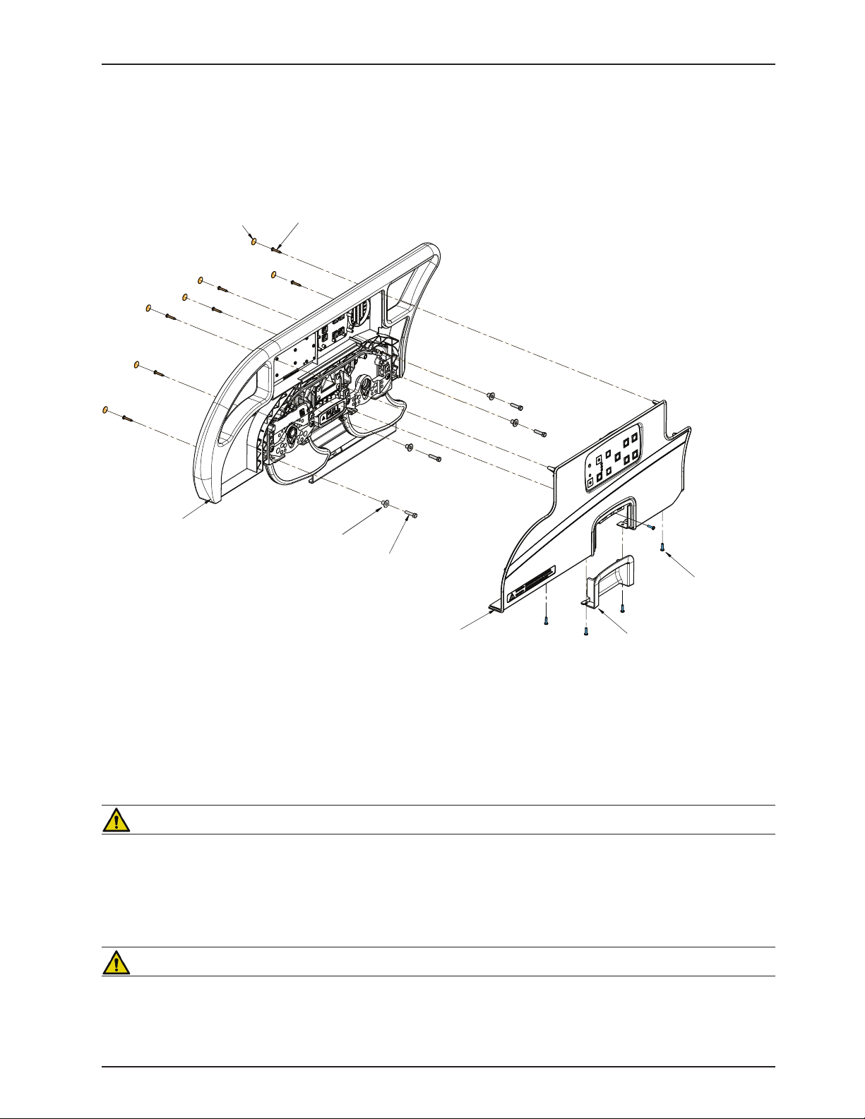
Release Handle Panel
(3006-400-533)
Outer Panel
(3006-400-125)
Hex Head
Machine Screw (4)
(0003-392-000)
Spacer (4)
(3006-400-574)
Siderail Fastener
Cover Label
(3006-400-522)
Tapping Screw
(0023-090-000)
Pan Head
Machine Screw (5)
(0050-005-000)
Inner Panel
(3006-400-130)
Service Information
HEAD AND FOOT SIDERAIL COVER REMOVAL
TOOLS REQUIRED:
#2 Phillips Screwdriver•
PROCEDURE:
Unplug the power cord from the wall receptacle.1.
Remove the seven screw cover labels from the inside of the rail.2.
Using a #2 Phillips screwdriver, remove the 8 phillips screws (A) holding the covers (B) to the siderail.3.
Remove the one screw holding the release handle panel and remove panel. 4.
CAUTION
There are two cables connecting the outside cover to the head end siderail. Be careful not to pull on them when
removing the cover.
Remove the cables from the siderail. Make note of the proper location for the cables.5.
Rever6. se the above steps to reattach the cover.
CAUTION
Do not snag the cables when installing the siderail cover.
www.stryker.com 300 6- 009 -102 REV C 67
Return To Table of Contents
Page 68
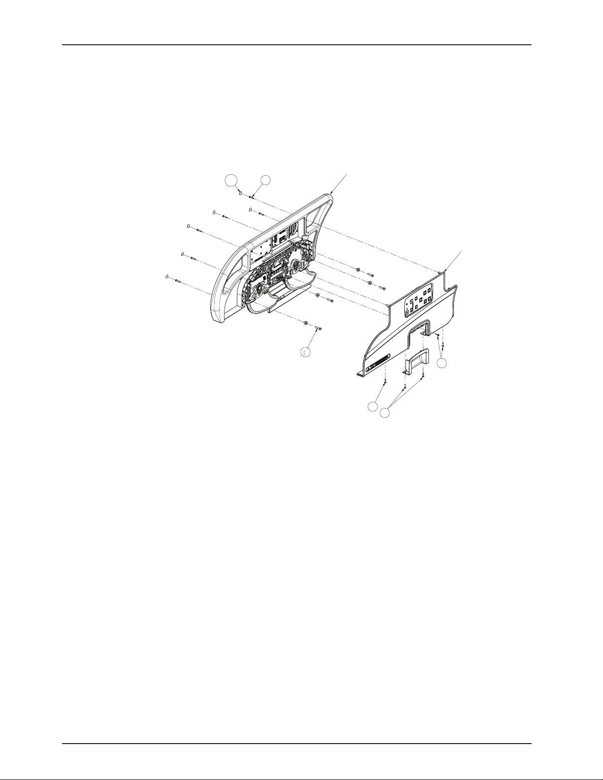
Service Information
C
D
D
Outer Panel
Head End
Siderail Hoop
Label
A
B
Screw
HEAD SIDERAIL HOOP REPLACEMENT
TOOLS REQUIRED:
#2 Phillips Screwdriver
3/8” Drive Ratchet
7/16” Socket
PROCEDURE:
Raise the siderail to the full upright position. 1.
Using a regular screwdriver, remove the six labels (A) on the inside of the siderail. 2.
Remove the six Pan Head screws (B) from the siderail panel.3.
Remove the two Pan Head screws (C) securing handle casing to panel and then pull down on the handle to 4.
remove.
Remove the three Pan Head screws (D) to remove the outer siderail panel.5.
Pull the outer siderail panel straight out.6.
Unplug the two cable harnesses from the siderail panel.7.
Unplug the cable connections from the inner siderail board and, using diagonal pliers, cut the cable ties securing 8.
the main cable.
Remove all four screws attached to the speaker and remove the speaker and cable clamp. 9.
Using a 7/16” socket, remove the four screws (E) holding the head siderail hoop to the siderail support 10.
assembly.
Lift the head siderail hoop straight up and out.11.
Remove the inner siderail boards and reinstall on the new head siderail hoop.12.
Reverse steps 2-11 to install a new siderail hoop. 13.
Return To Table of Contents
68 3006-009-102 REV C www.stryker.com
Page 69

Service Information
FOOTBOARD MODULE REMOVAL
TOOLS REQUIRED:
#2 Phillips Screwdriver •
1/4” Nut Driver•
Note
Labels will need to be replaced.
PROCEDURE:
Remove the footboard assembly.1.
Remove the 11 screw cover labels.2.
Using a Phillips screwdriver, remove the 13 screws holding the back cover to the footboard.3.
Using a 1/4” nut driver, remove the six screws holding the center lens assembly in. 4.
Unplug the cable connection from the module.5.
Note
If you have iAwareness, there are two other connections.
Lift the module out and replace.6.
Reverse the above steps to attach the replacement door and/or hinge.7.
Note
Screw (B) is a machine screw and must be reinstalled in the proper hole.
Return To Table of Contents
www.stryker.com 300 6- 009 -102 REV C 69
Page 70
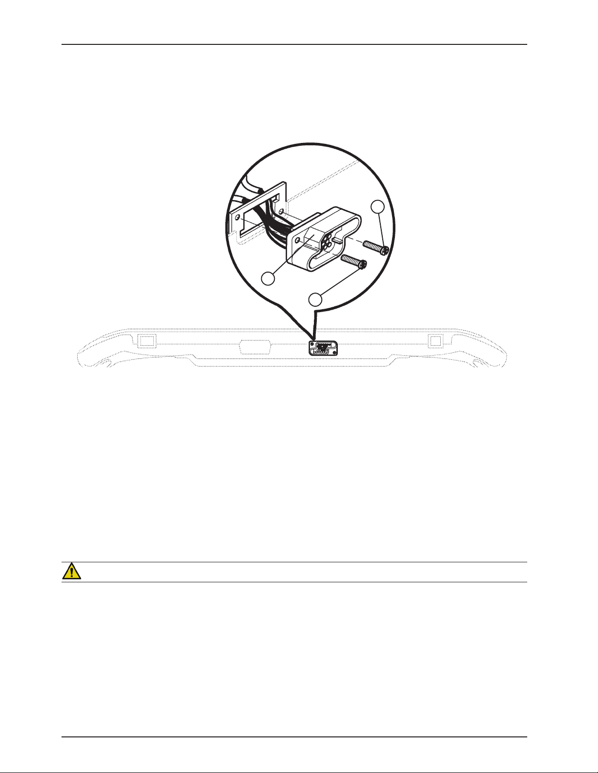
BOTTOM VIEW OF FOOT BOARD
A
B
A
Service Information
FOOTBOARD INTERFACE PLUG REPLACEMENT
TOOLS REQUIRED:
#2 Phillips Screwdriver•
PROCEDURE:
Remove the footboard assembly.1.
Remove the 11 screw cover labels.2.
Using a Phillips screwdriver, remove the 13 screws holding the back cover to the footboard.3.
Unplug the cable connection from the module.4.
Lift up on connector and replace. 5.
CAUTION
Be sure to install the plug with the flat edge (B) at the top left, as shown in the illustration, or the footboard interface
plug will not mate properly with the bed. Damage to the plug or the footboard could result.
Return To Table of Contents
70 30 06-00 9-102 REV C www.stryker.com
Page 71
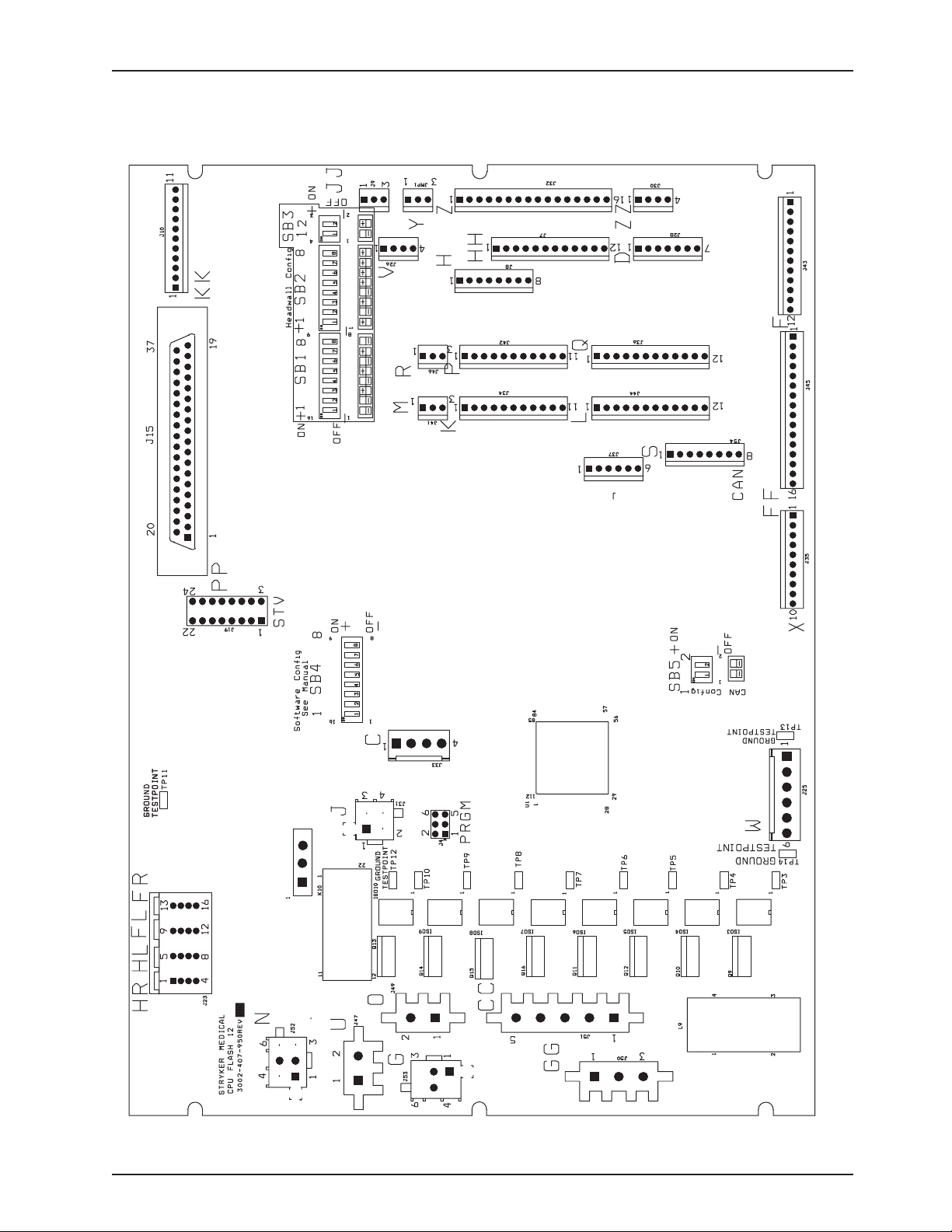
J55
LL
CPU BOARD: 3006-307-900
Bed Circuit Boards
Return To Table of Contents
www.stryker.com 300 6- 009 -102 REV C 71
Page 72

Bed Circuit Boards
CPU BOARD: 3006-307-900 (CONTINUED)
Cable Location Voltage Positive Lead Negative Lead Description
W +12VD C Pin 1 Pin 4 or 5 Relays & Siderails
Light Voltage
W +5VDC Pin 2 & 3 Pin 4 or 5 +5VDC from
Power Supply
W -12VDC Pin 6 Pin 4 or 5 Relays & Siderails
Light Voltage
J +5VDC Pin 4 Pin 2 +5VDC for Head
Lift Potentiometer
J 0 - 5VDC Pin 3 Pin 2 Head Lift
Potentiometer Wiper
C +5VDC Pin 1 Pin 2 +5VDC for Foot
Lift Potentiometer
C 0 - 5VDC Pin 3 Pin 2 Foot Lift
Potentiometer Wiper
GG 0VAC w/o Switch
120VAC w/Switch
GG 0VAC w/o Switch
120VAC w/Switch
CC 0VAC w/o Switch
120VAC w/Switch
CC 0VAC w/o Switch
120VAC w/Switch
O 110VAC Pin 1 Pin 2 Line Voltage to Bed
N 0VAC w/o Switch
120VAC w/Switch
N 0VAC w/o Switch
120VAC w/Switch
G 0VAC w/o Switch
120VAC w/Switch
G 0VAC w/o Switch
120VAC w/Switch
Pin 2 Purple Pin 1 Blue Gatch Up
Pin 3 Red Pin 1 Blue Gatch Down
Pin 1 Black Pin 3 Red Fowler Up
Pin 2 White Pin 3 Red Fowler Down
Pin 3 Black Pin 1 White Head Lift Down
Pin 6 Red Pin 1 White Head Lift Up
Pin 3 Black Pin 1 Red Foot Lift Down
Pin 6 White Pin 1 Red Foot Lift Up
Return To Table of Contents
72 30 06-00 9-102 REV C www.stryker.com
Page 73
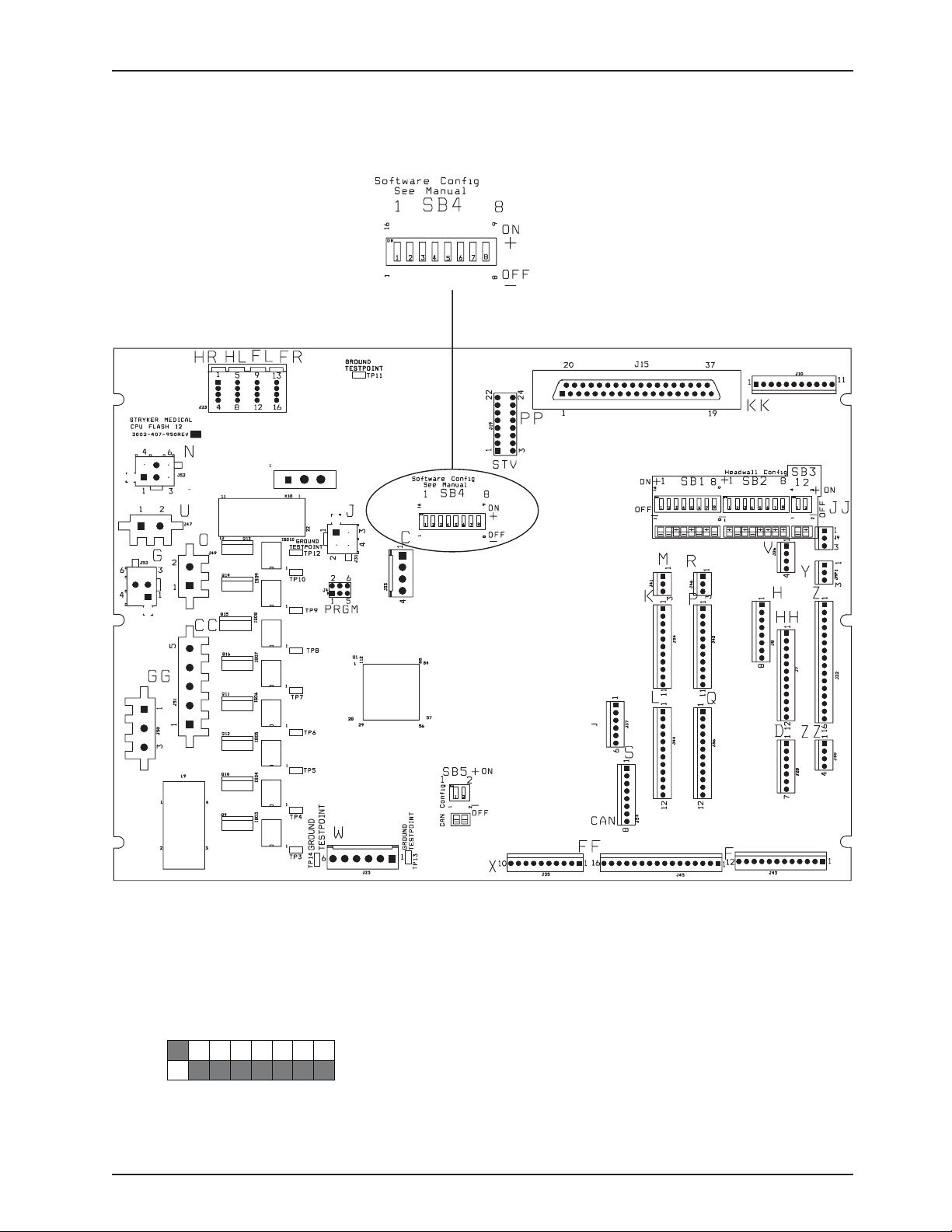
J55
LL
ON
OFF
1 2 3 4 5 6 7
8
SOFTWARE CONFIGURATION
Bed Circuit Boards
Locate switch bank 4, labeled SB4 on the CPU board (see above).1.
Move switch one to the “ON” position (see below).2.
To verify the switch settings, check what the footboard LCD displays.3.
General Setting, S3 Bed
Return To Table of Contents
www.stryker.com 300 6- 009 -102 REV C 73
Page 74
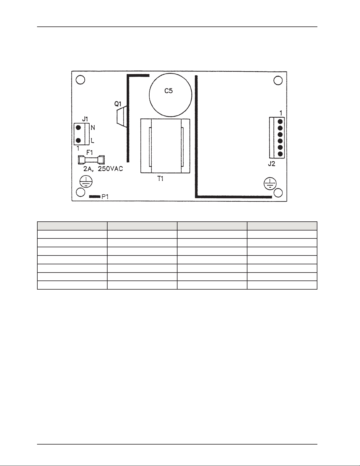
POWER SUPPLY: 0059-157-000
Bed Circuit Boards
Connector Location Voltage Positive Lead Negative Lead
J1 110 V Pin 1 Pin 2
J2 12V Pin 1 Pin 4 or 5
J2 5V Pin 2 Pin 4 or 5
J2 5V Pin 3 Pin 4 or 5
J2 GND Pin 4 Pin 4 or 5
J2 GND Pin 5 Pin 4 or 5
J2 -12 V Pin 6 Pin 4 or 5
Return To Table of Contents
74 300 6- 009 -102 REV C www.stryker.com
Page 75
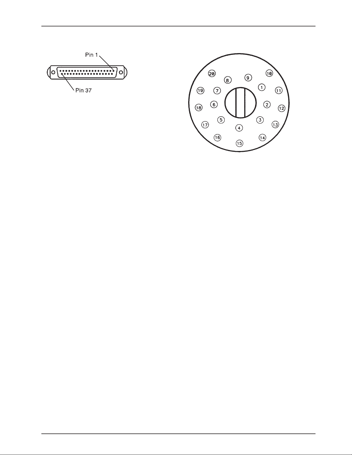
Head Wall Output Configuration
37-Pin Connector
Pin 1 Option 2 Common
Pin 2 Read Light
Pin 3 Room Light
Pin 4 Speaker High
Pin 5 Potentiometer Wiper
Pin 6 Radio Common
Pin 7 Nurse Call Interlock
Pin 8 Audio Transfer Pin 9 Audio Transfer +
Pin 10 Interlock +
Pin 11 Interlock Pin 12 Spare
Pin 13 Options 3 Common
Pin 14 Potentiometer Low Common
Pin 15 Potentiometer High
Common (Std.)/Audio (STV)
Pin 16 Nurse Answer Light +
Pin 17 Option 1 NO/NC
Pin 18 Option 1 Common
Pin 19 Nurse Call Light +
Pin 20 Option 2 NO/NC
Pin 21 Option 3 NO/NC
Pin 22 Option 3A NO/NC
Pin 23 Option 2A Common
Pin 24 Option 2A NO/NC
Pin 25 Nurse Call +
Pin 26 Nurse Call NO/NC
Pin 27 Room/Read Light Common
Pin 28 Nurse Call Light Pin 29 Nurse Answer Light Pin 30 Priority NO/NC
Pin 31 Priority Common
Pin 32 Option 3A Common
Pin 33 TV - (Std.)/Data (STV)
Pin 34 TV + (Std.)/Common (STV)
Pin 35 Speaker Low Common
Pin 36 Audio Shield
Pin 37 Radio NO/NC
Stryker Pendant Port
1 Scan Line
2 Audio (-)
3 Nurse Call (+)
4 +5 VDC
5 Scan Line
6 Scan Line
7 Nurse Call (-)
8 TV Channel Up
9 Backlight
10 Audio (+)
11 Gatch Up/Fowler In/Foot Up/DMS Firm
12 Gatch Down/Fowler Out/Foot Out/DMS Soft
13 Fowler Up/Trend In
14 Fowler Down/Trend Out
15 Audio Shield
16 Not Used - Socket Filled
17 Bed Up
18 Ground
19 Read Light/Bed Down
20 Room Light
Return To Table of Contents
www.stryker.com 300 6- 009 -102 REV C 75
Page 76
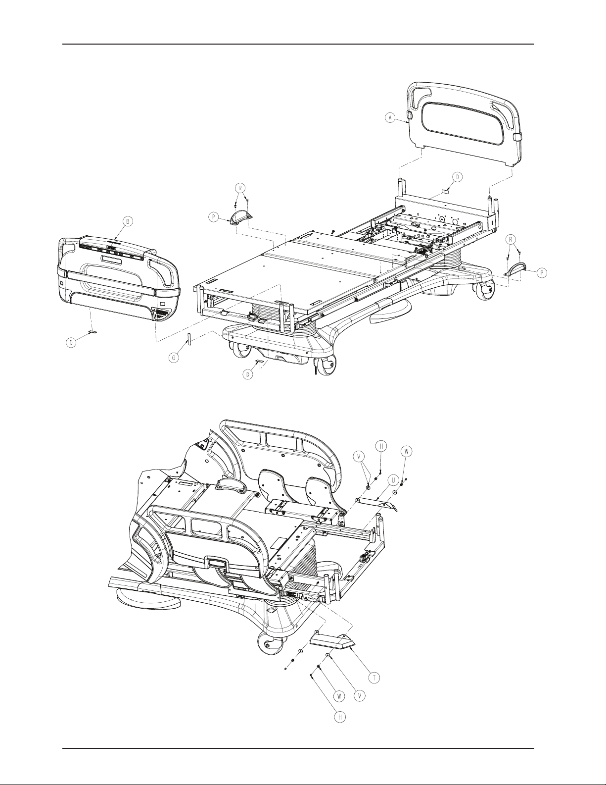
Bed Assembly, Standard Bed
For Reference Only: 3006-063-102
Return To Table of Contents
76 3006 -00 9-102 REV C www.stryker.com
Page 77
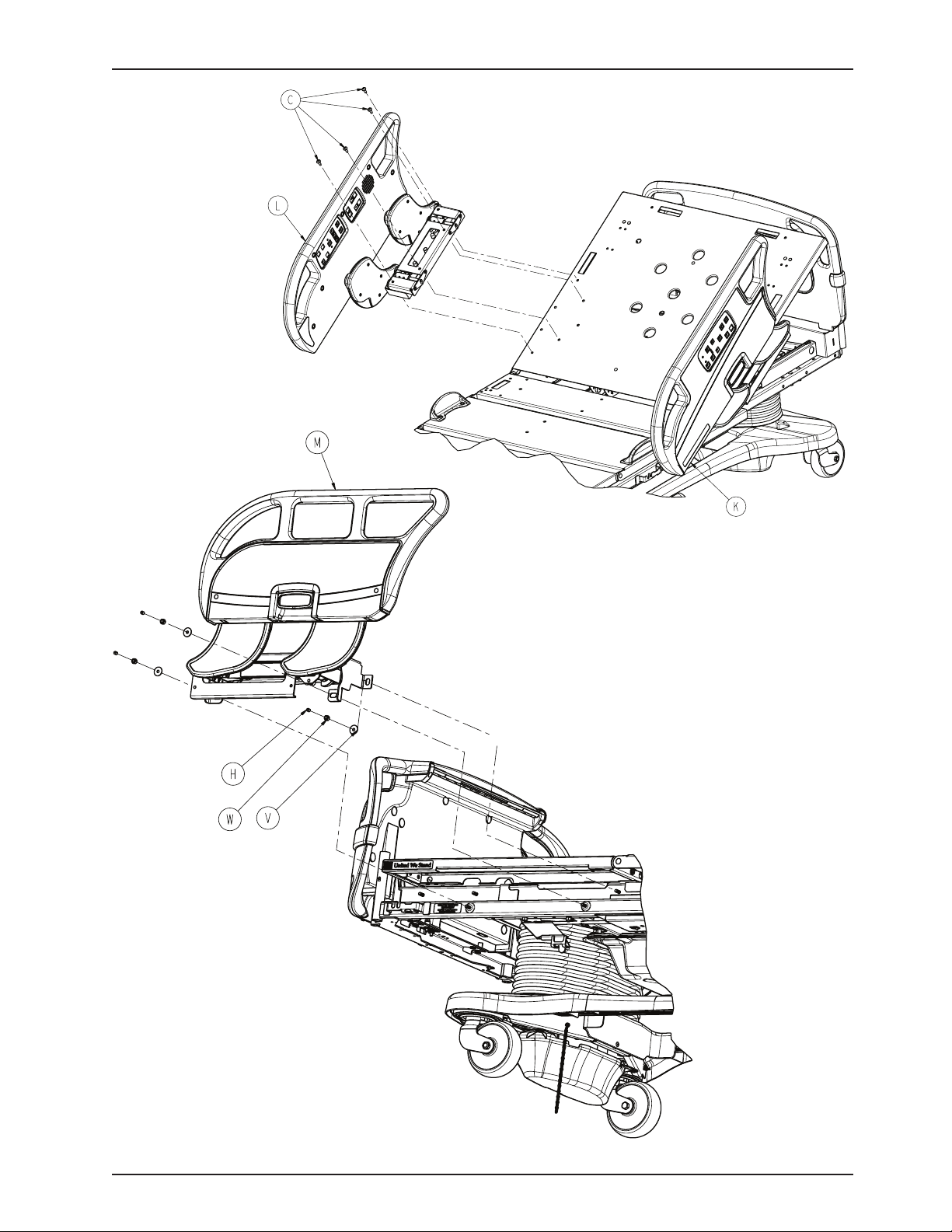
Bed Assembly, Standard Bed
Return To Table of Contents
www.stryker.com 300 6- 009 -102 REV C 77
Page 78
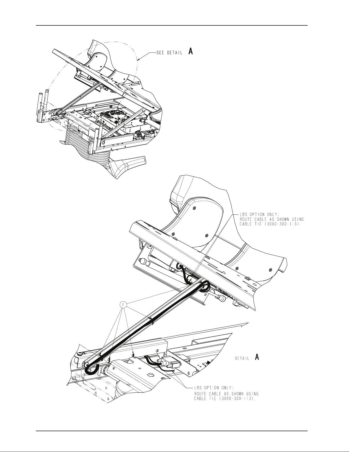
Bed Assembly, Standard Bed
Return To Table of Contents
78 30 06-009-102 REV C w ww.stryker.com
Page 79
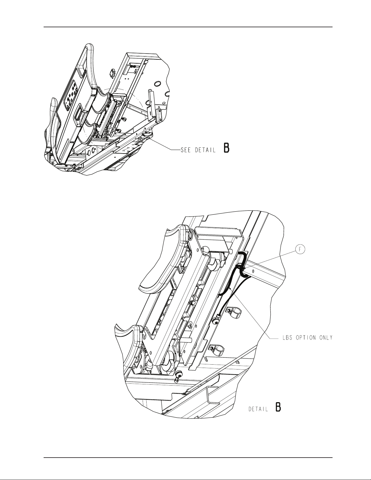
Bed Assembly, Standard Bed
Return To Table of Contents
www.stryker.com 300 6- 009 -102 REV C 79
Page 80
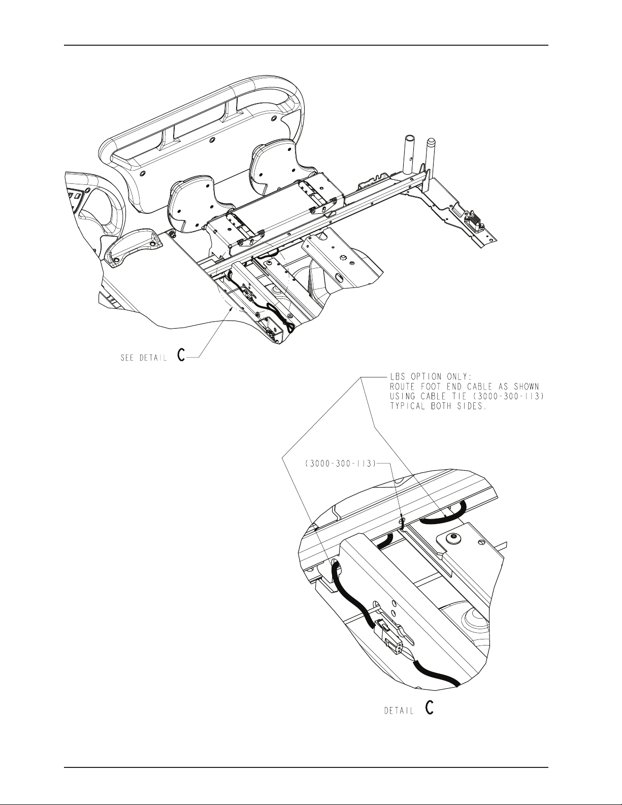
Bed Assembly, Standard Bed
Return To Table of Contents
80 300 6-009 -102 REV C www.stryker.com
Page 81

Bed Assembly, Standard Bed
Bed Assembly, Standard Bed, Components - 3006-063-102 (Reference Only)
Item Part No. Part Name Qty.
A 3006-660-010 Head Board Assembly (see pg. 200) 1
B 3006-560-000 Footboard Assembly, Standard
Components (see pg. 188) 1
C 0007-065-000 Truss Head Screw 8
D 3000-300-625 Date of Manufacture Label 1
F 3000-300-113 8” Cable Tie 10
G 3000-300-641 Footboard Ground Label 1
H 3006-400-493 Stud Cap 10
J 3006-363-002 Litter Assembly (see pg. 112) 1
K 3006-460-105 HE Siderail Assembly, Left (pg. 155) 1
L 3006-460-205 HE Siderail Assembly, Right (pg. 155) 1
M 3006-460-300 FE Siderail Assembly, Left (pg. 176) 1
N 3006-460-400 FE Siderail Assembly, Right (pg. 176) 1
P 3006-300-033 Mattress Retainer 2
R 0025-120-000 Rivet 4
T 3006-300-275 Shield, Right 1
U 3006-300-276 Shield, Left 1
V 0011-180-000 Flat Washer 10
W 0016-028-000 Fiberlock Hex Nut 10
Y 0059-126-000 Push Mount Wire Clip 2
Return To Table of Contents
www.stryker.com 300 6- 009 -102 REV C 81
Page 82
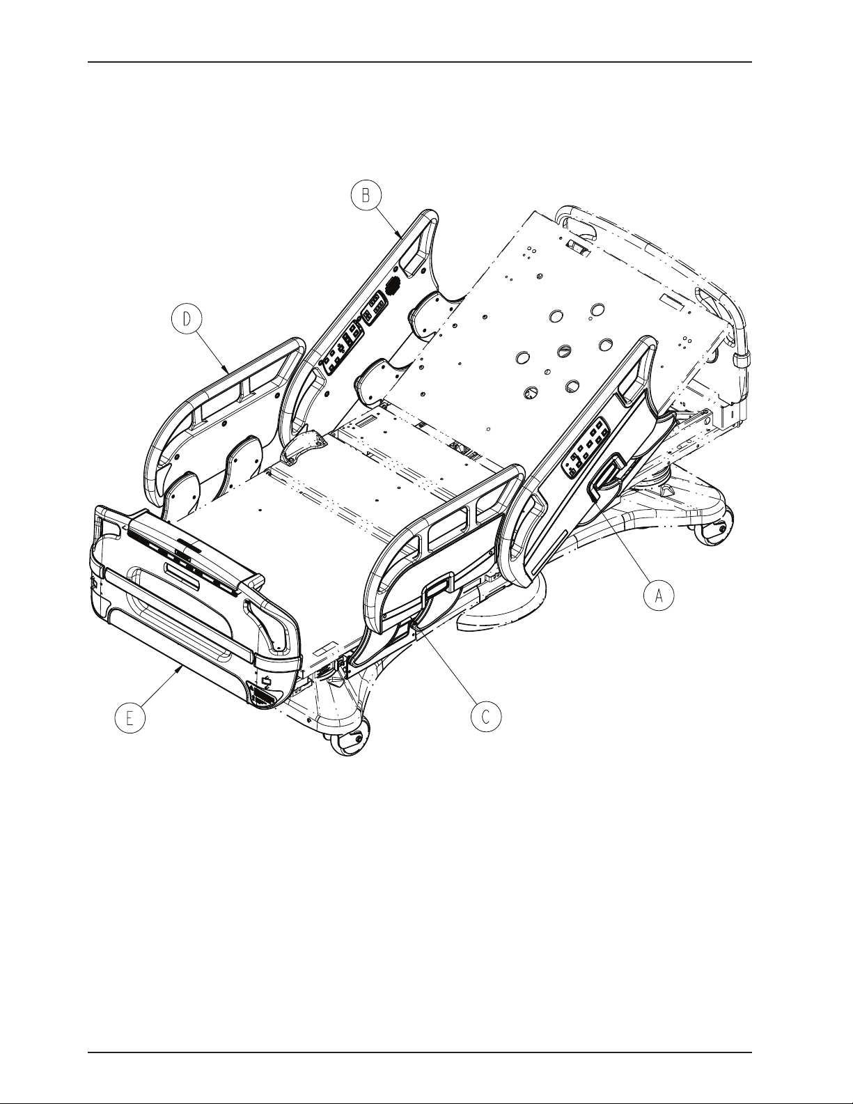
Bed Assembly, iBed Awareness Option
(Scale, Bed Exit, Zone Control)
For Reference Only: 3006-560-115
Return To Table of Contents
82 3006- 009 -102 REV C www.stryker.com
Page 83
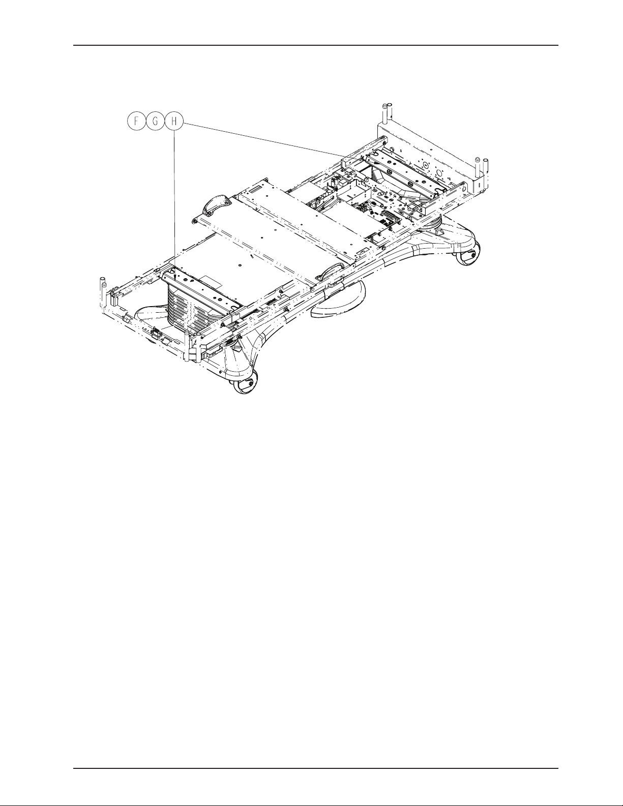
Bed Assembly, iBed Awareness Option
(Scale, Bed Exit, Zone Control)
iBed Awareness Option Components - 3006-560-115 (Reference Only)
item Part No. Part Name Qty.
A 3006-460-100 Head End Siderail Assembly, LH
(see pg. 173) 1
B 3006-460-200 Head End Siderail Assembly, RH
(see pg. 174) 1
C 3006-460-305 Foot End Siderail Assembly, LH
(see pg. 18 4) 1
D 3006-460-405 Foot End Siderail Assembly, RH
(see pg. 18 5) 1
E 3006-560-100 Footboard Assembly (see pg. 196) 1
F 3002-317-003 Scale/Bed Exit Option Assembly 1
G 3006-326-501 Load Cell Bed Lift Header Assembly
(see pg. 13 5) 1
H 3006-307-501 Load Cell Bed Lift Header Assembly
(see pg. 13 5) 1
Return To Table of Contents
www.stryker.com 300 6- 009 -102 REV C 83
Page 84
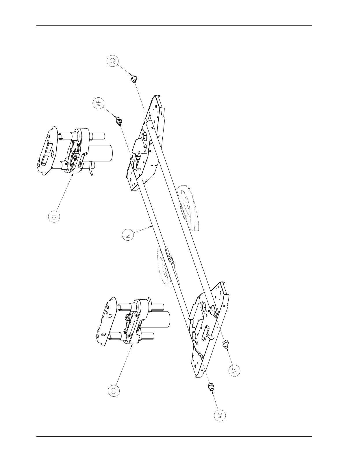
Base Assembly, Common Components
For Reference Only: 3006-200-002
Return To Table of Contents
84 3006- 009 -102 REV C ww w.stryker.com
Page 85
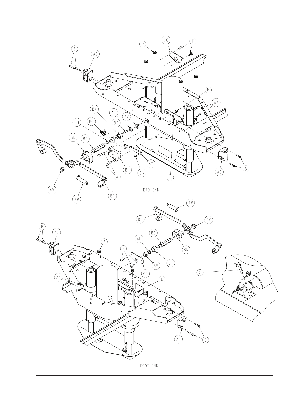
Base Assembly, Common Components
Return To Table of Contents
www.stryker.com 300 6- 009 -102 REV C 85
Page 86
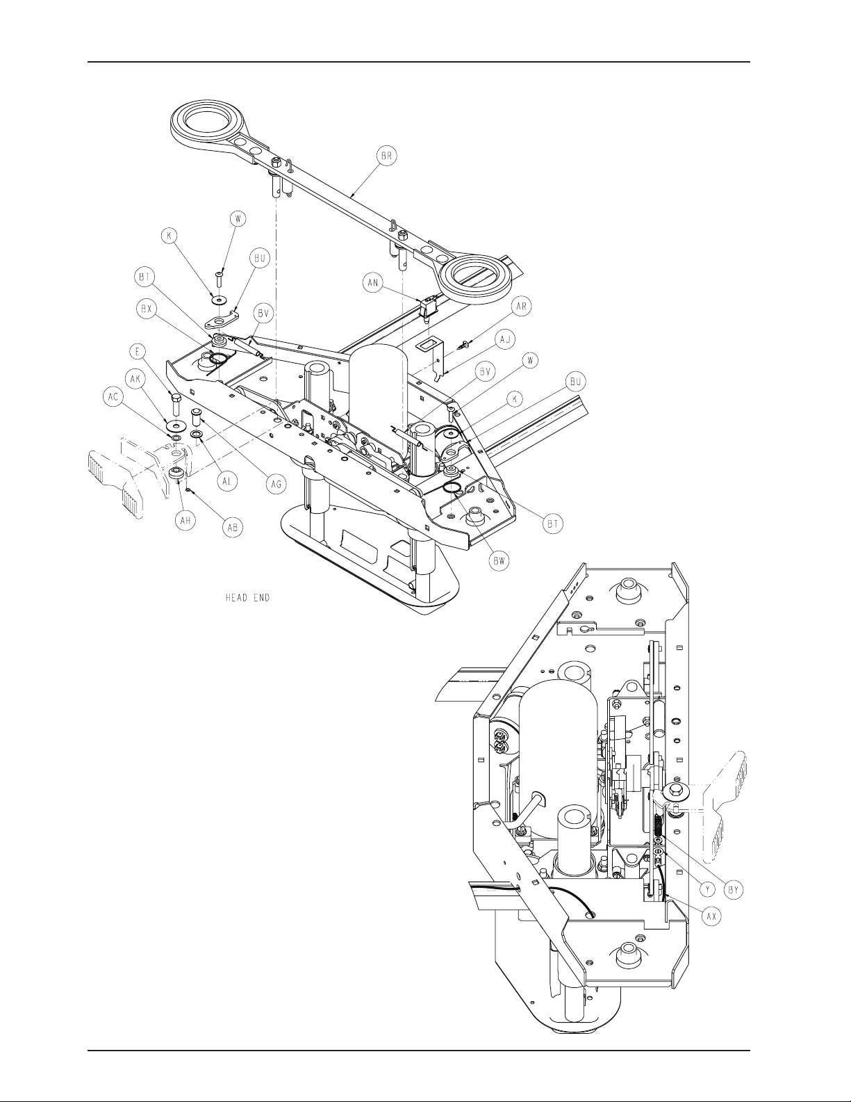
Base Assembly, Common Components
Return To Table of Contents
86 300 6- 009 -102 REV C www.stryker.com
Page 87
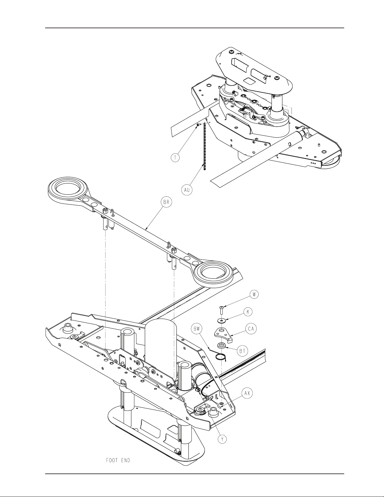
Base Assembly, Common Components
Return To Table of Contents
www.stryker.com 300 6- 009 -102 REV C 87
Page 88
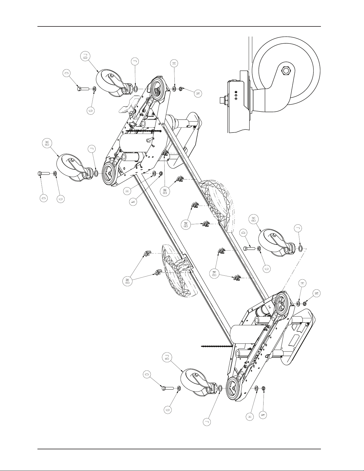
Base Assembly, Common Components
Return To Table of Contents
88 300 6- 009 -102 REV C www.stryker.com
Page 89
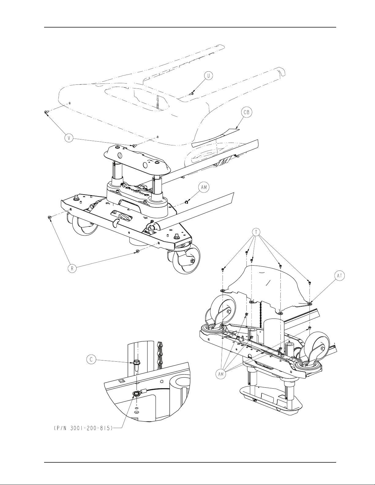
Base Assembly, Common Components
Typical Both Ends
Return To Table of Contents
www.stryker.com 300 6- 009 -102 REV C 89
Page 90

Base Assembly, Common Components
Base Assembly, Common Components - 3006-200-002 (Reference Only)
Item Part No. Part Name Qty.
A 0003-074-000 Hex Head Cap Screw 2
B 0003-122-000 Hex Washer Head Screw 8
C 0003-224-000 Hex Washer Head Screw 2
D 0003-333-000 Hex Head Cap Screw 4
E 0003-349-000 Hex Head Cap Screw 1
F 0007-052-000 Truss Head Torx 4
G 0011-310-000 Washer 4
H 0011-333-000 Washer 4
J 0011-343-000 Washer 4
K 0011-611-000 Washer 5
L 0016-002-000 Fiberlock Hex Nut 8
M 0016-028-000 Fiberlock Hex Nut 2
N 0016-049-000 Nylock Hex Nut 4
P 0016-098-000 Hex Flange Nut 8
R 0018-036-000 Plastic Clip Nut 4
T 0023-025-000 Slotted Hex Washer Head Screw 12
U 0023-080-000 Truss Head Screw 2
V 0023-092-000 Truss Head Phillip Screw 4
W 0025-191-000 Rivet 5
X 0026-014-000 Roll Pin 4
Y 0030-052-000 Heyco Snap Bushing 2
AA 0038-151-000 Cable Tie 4
AB 0045-008-000 O-Ring 1
AC 0052-305-000 Washer 1
AD 3000-200-305 Brake Shaft Bushing, RH 2
AE 3000-200-328 Brake Shaft Bushing 4
AF 3000-200-331 Brake Shaft Bushing, LH 2
AG 3000-200-337 Pushfit Ball Plunger 1
AH 3000-200-341 Steer Pedal Bushing 1
AJ 3000-200-343 Brake Switch Bracket 1
AK 3000-200-348 Wide Special Washer 1
AL 3000-200-349 Narrow Special Washer 3
AM 3000-300-002 Plastic Clip Nut 12
AN 3000-300-058 Plunger Switch 1
AP 3000-300-113 8” Cable Tie 4
AR 3000-300-115 Standoff 1
AT 3001-200-022 Bottom Cover Assembly(see pg. 106) 2
AU 3001-200-052 Grounding Chain 2
AV 3001-200-317 Cam Shaft Brake Bushing 4
AW 3001-200-334 Spring 2
AX 3001-200-342 Steer/Lock Cable 1
AY 3002-200-302 Brake Ratchet Link Assembly 1
BA 3002-200-305 Brake Ratchet Crank, Left 1
BB 3002-200-306 Brake Ratchet Crank, Right 1
BC 3002-200-307 Brake Latch Spring 1
BD 3002-200-308 Brake Ratchet Crank Pin 1
BE 3002-200-311 Brake Shaft 2
BF 3002-200-313 Brake Cam Spacer 1
BG 3002-200-316 Brake Track Roller 1
Return To Table of Contents
90 3006-009-102 REV C www.stryker.com
Page 91

Base Assembly, Common Components
Base Assembly, Common Components - 3006-200-002 (Reference Only) (Continued)
Item Part No. Part Name Qty.
BH 3002-201-301 Brake Ratchet Track 1
BJ 3006-200-060 Swivel Lock Caster Assembly 2
BK 3006-200-065 Steer/Swivel Caster Assembly, White 2
BL 3006-200-102 Base Weldment 1
BM 3006-200-306 Brake Shaft Pedal Bearing 8
BN 3006-200-312 Brake Cam 2
BP 3006-200-330 Brake Crank Assembly (see pg. 101) 2
BR 3006-200-335 Brake Bar Assembly (see pg. 102) 2
BT 3006-200-339 Steer/Swivel Lever Bushing 5
BU 3006-200-374 Swivel Lever 4
BV 3006-200-376 Swivel Lock Activation Spring 4
BW 3006-200-378 Swivel Lock Return Spring, RH 3
BX 3006-200-379 Swivel Lock Return Spring, LH 2
BY 3006-200-380 Steer Extension Spring 1
CA 3006-200-381 Steer/Swivel Lever 1
CB 3006-200-601 Brake Pedal Label 2
CC 3006-201-315 Brake Mounting Bracket, White 2
CD 3006-301-201 Lift Assembly, HE (see pg. 94) 1
CE 3006-301-251 Lift Assembly, FE (see pg. 94) 1
Return To Table of Contents
www.stryker.com 300 6- 009 -102 REV C 91
Page 92
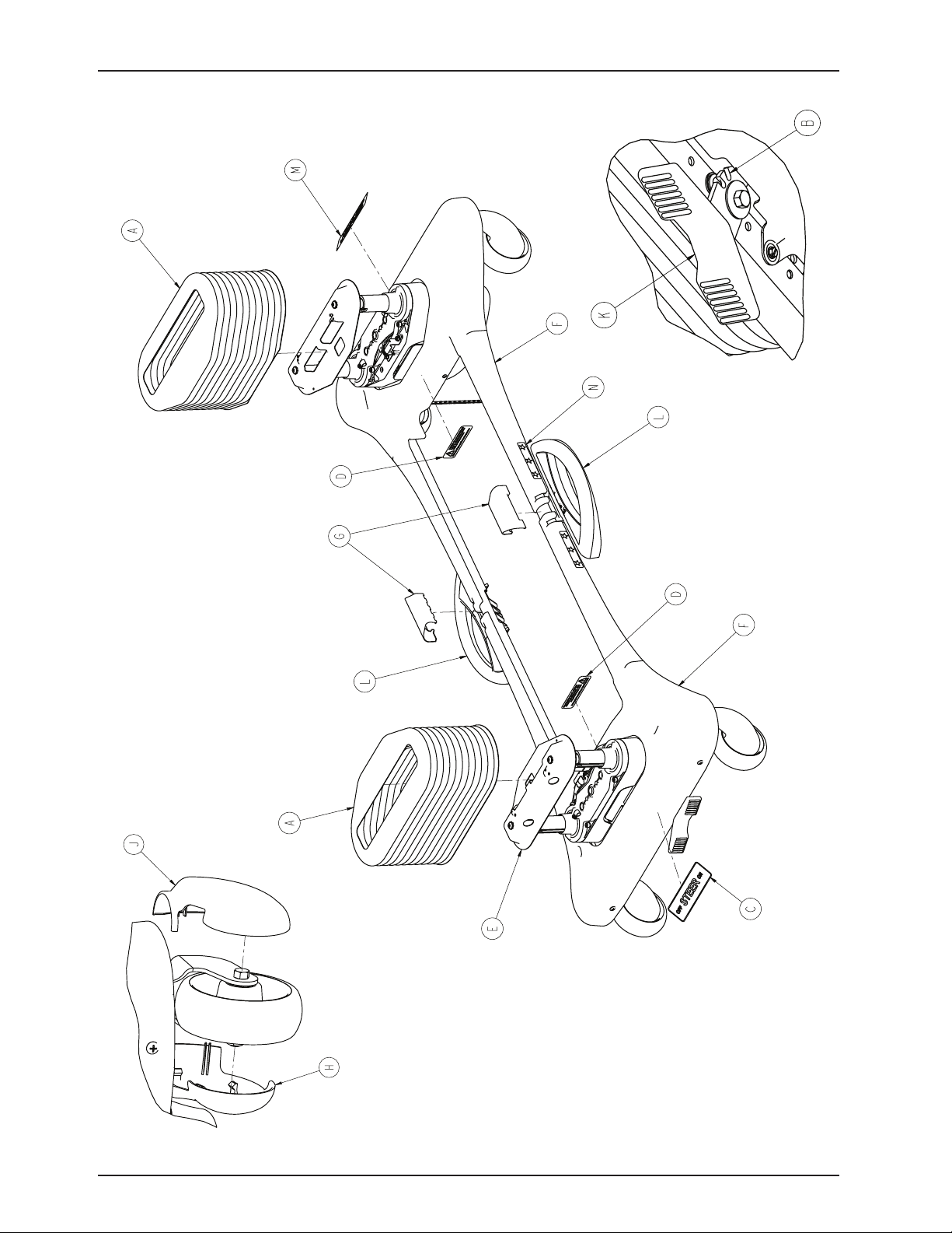
Base Assembly, Standard Bed
For Reference Only: 3006-260-003
Return To Table of Contents
92 3006- 009 -102 REV C www.stryker.com
Page 93

Base Assembly, Standard Bed
Base Assembly, Patriot Bed - 3006-260-003 (Reference Only)
Item Part No. Part Name Qty.
A 2030-001-103 Dark Blue Trim Bellows 2
B 3001-200-371 Black Steer Pedal Arm Assembly 1
C 3006-060-013 Steer/Lock Label 1
D 3006-060-708 Shock Hazard Label 2
E 3006-200-002 Base Assembly, Common Comp.
(see pg. 84) 1
F 3006-260-009 Uni-Pan Cover, Blue 2
G 3006-260-011 Uni-Pan Cover Clip, Blue 2
H 3006-260-138 6” Caster Cover, LH, Blue 4
J 3006-260-139 6” Caster Cover, RH, Blue 4
K 3006-260-336 Steer Pedal Cover, Blue 1
L 3006-260-340 Brake Shaft Assembly (see pg. 100) 2
M 3006-260-602 Base Logo Label 1
N 3006-260-603 Base Stars Label 4
Return To Table of Contents
www.stryker.com 300 6- 009 -102 REV C 93
Page 94
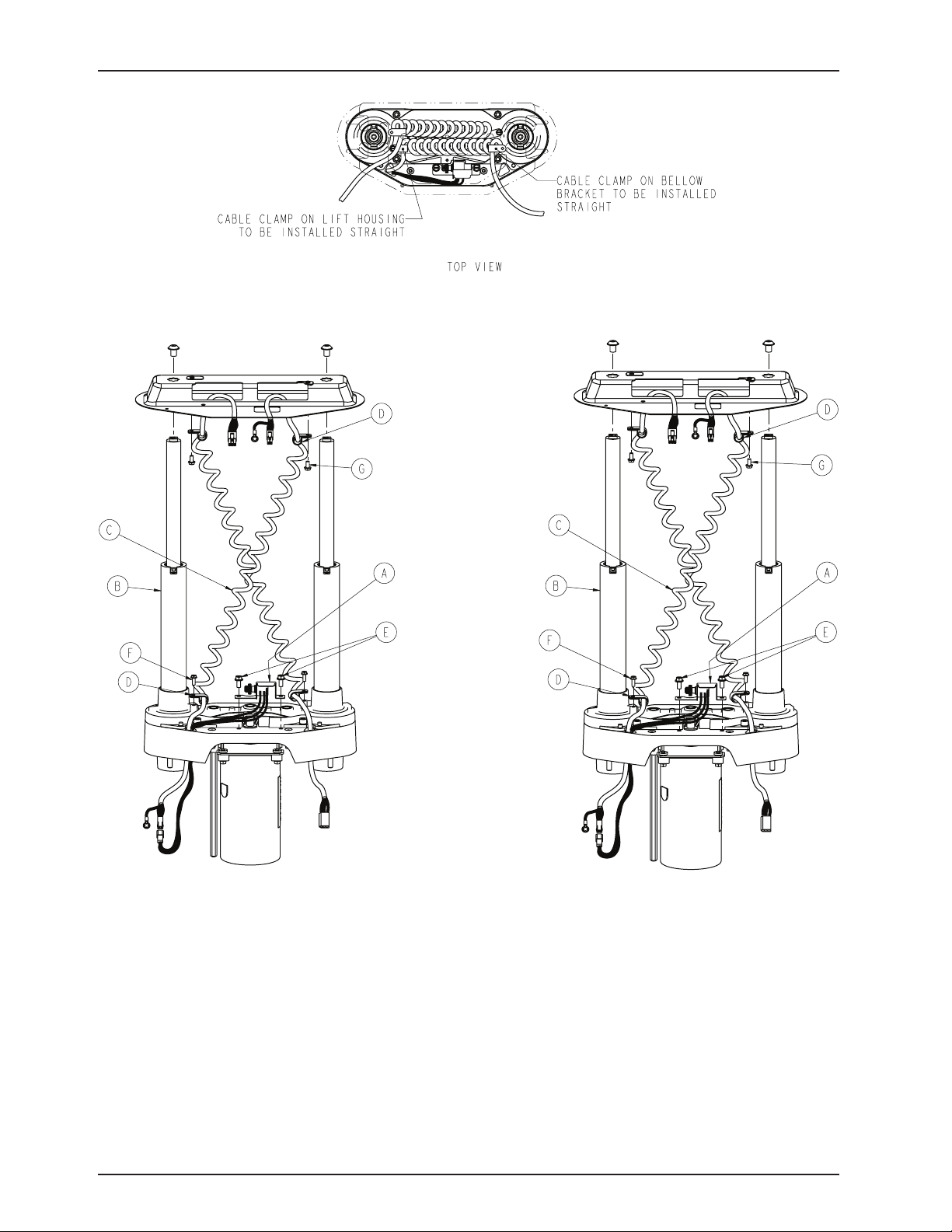
Lift Assembly (Head and Foot End)
HEAD END: 3006-301-201 FOOT END: 3006-301-251
Lift Assembly, Head End - 3006-301-2001 / Foot End - 3006-301-251
Item Part No. Part Name Qty.
A 3006-200-240 HE Potentiometer Assembly 1
3001-200-230 FE Potentiometer Assembly 1
B 3006-200-275 Common Lift Assembly (see pg. 95) 1
C 3006-200-815 Sensor Coil Cord 1
D 0034-022-000 Cable Clamp, Head End 2
0034-021-000 Cable Clamp, Foot End 2
E 0003-121-000 Hex Washer Head Screw 2
F 0003-128-000 Hex Washer Head Screw 1
J 0023-164-000 Hex Washer Head Screw 1
Return To Table of Contents
94 3006- 009 -102 REV C www.stryker.com
Page 95
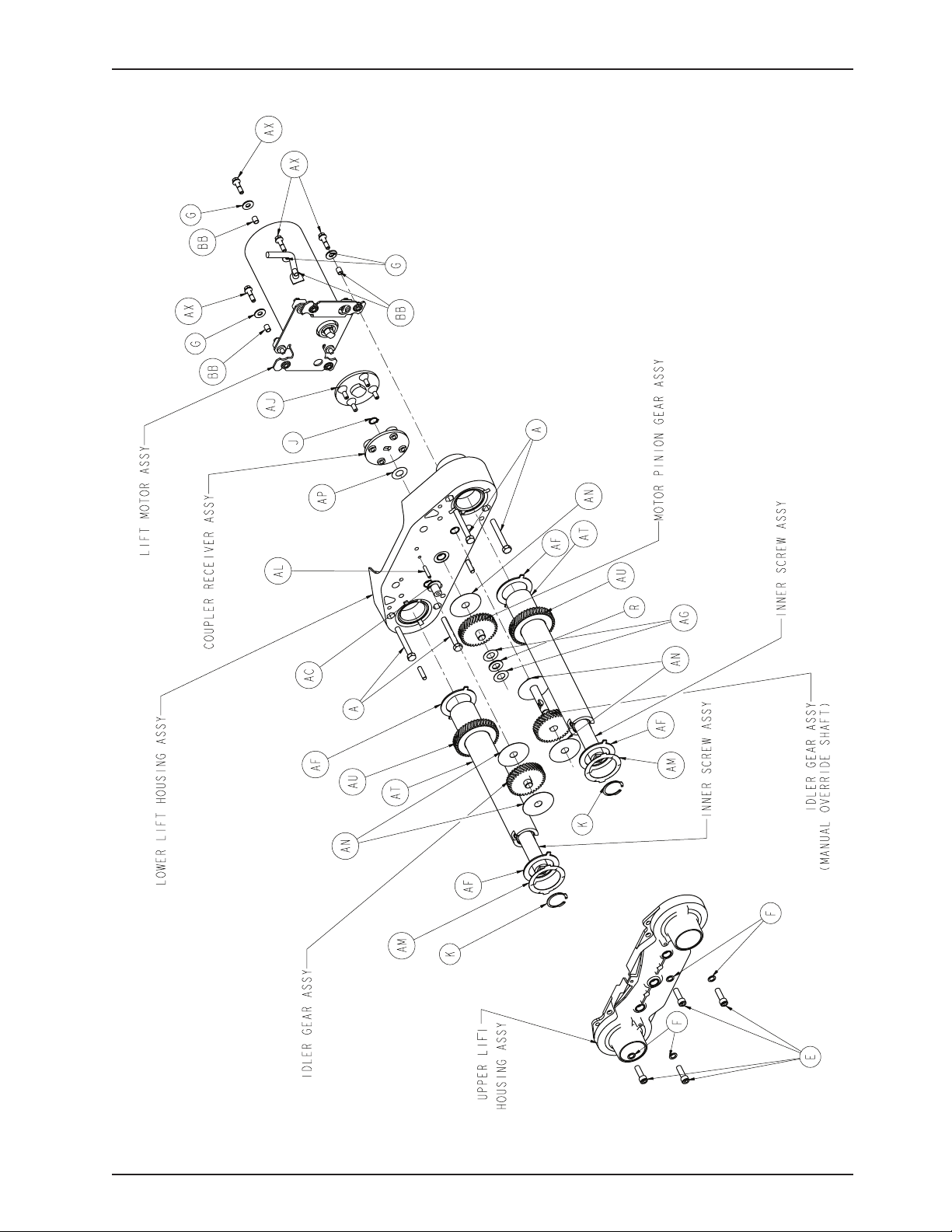
Lift Assembly
For Reference Only: 3006-200-275
Return To Table of Contents
www.stryker.com 300 6- 009 -102 REV C 95
Page 96
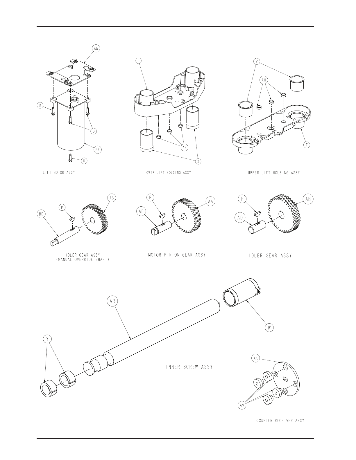
Lift Assembly
Return To Table of Contents
96 3006-009 -102 REV C www.stryker.com
Page 97
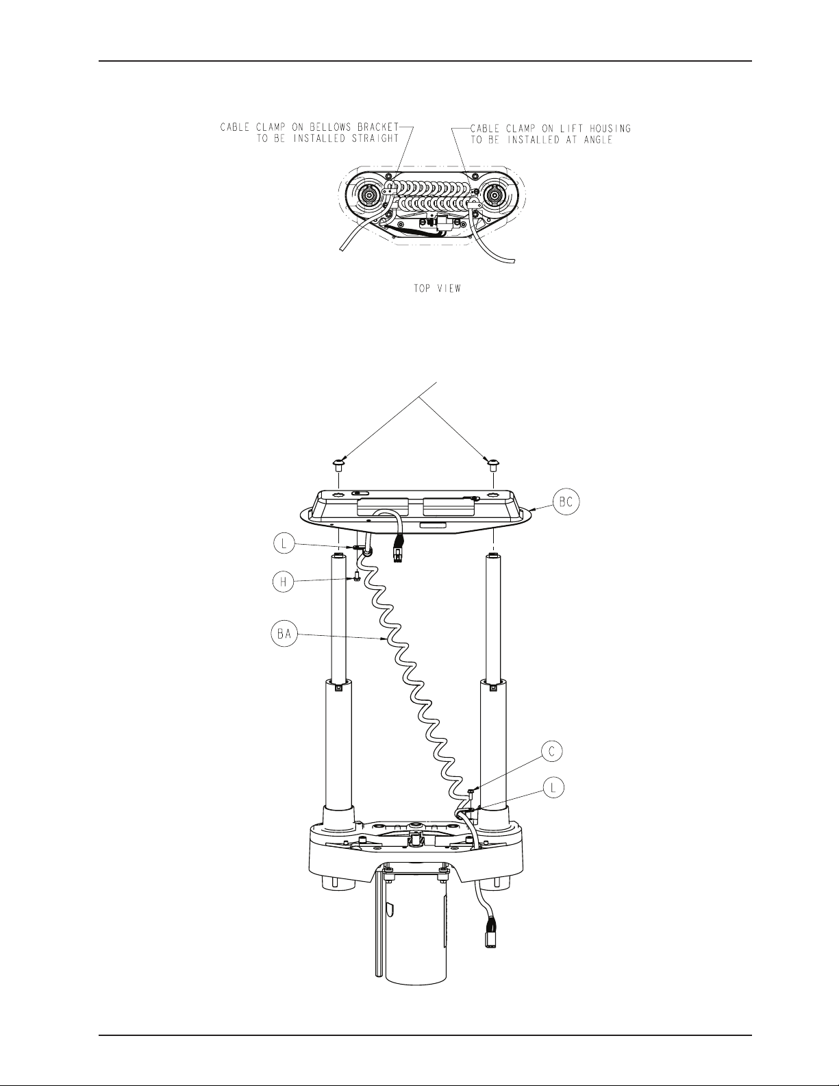
0004-245-000
(Holds Bellow Brackets)
Lift Assembly
Return To Table of Contents
www.stryker.com 300 6- 009 -102 REV C 97
Page 98

Lift Assembly
Lift Assembly Common Components - 3006-200-275 (Reference Only)
Item Part No. Part Name Qty.
A 0003-082-000 Hex Head Cap Screw 4
C 0003-128-000 Hex Washer Head Screw 1
D 0003-331-000 Hex Washer Head Screw 4
E 0004-213-000 Socket Head Cap Screw 4
F 0011-308-000 Serrated Washer 4
G 0011-408-000 Flat Washer 4
H 0023-164-000 Hex Washer Head Screw 1
J 0028-097-000 Retaining Ring 1
K 0028-121-000 Retaining Ring 2
L 0034-022-000 Cable Clamp 2
N 0051-022-000 Syn-Tech Grease 4
P 0058-044-000 #404 Woodruff Key 3
R 0081-212-000 Needle Roller Bearing 1
T 3000-200-201 Upper Lift Housing 1
U 3000-200-202 Lower Lift Housing 1
V 3000-200-204 Upper Housing Sleeve 2
W 3000-200-205 Upper Stage Nut 2
X 3000-200-207 Lower Stage Nut 2
Y 3000-200-208 Glide Bushing 4
AA 3000-200-209 Motor Pinion 1
AB 3000-200-210 Idler Gear 2
AC 3000-200-216 Potentiometer Drive Gear 1
AD 3000-200-218 Lift Idler Shaft 1
AE 3000-000-220 Input Pinion Shaft 1
AF 3000-200-223 Output Gear Thrust Washer 4
AG 3000-200-224 Input Gear Thrust Washer 2
AH 3000-200-226 Pinion Shaft Bushing 6
AJ 3000-200-233 Lift Motor Coupling 1
AK 3000-200-234 Coupler Receiver 1
AL 3000-200-239 Drive Gear Shaft, Pot 1
AM 3000-200-241 Wave Spring Washer 2
AN 3000-200-245 Gear Washer 5
AP 3000-200-246 Nylon Washer 1
AR 3000-200-249 Inner Screw 2
AT 3000-200-251 Tube Screw 2
AU 3000-200-252 Output Gear 2
AV 3000-300-455 Isolation Bushing 4
AW 3001-200-214 Isolation Plate Assembly (pg. 99) 1
AX 3001-200-228 Mounting Standoff 4
BA 3001-200-864 Power Coil Cable 1
BB 3001-300-019 Isolation Sleeve 4
BC 3002-200-052 Bellows Bracket 1
BD 3002-200-235 Manual Override Shaft, Idler 1
BE 3003-016-603 Lift Motor 1
Return To Table of Contents
98 300 6-009 -102 REV C www.stryker.com
Page 99
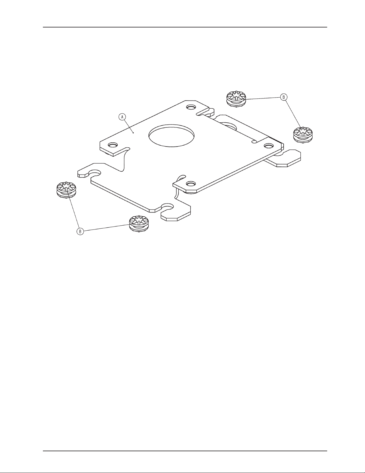
Motor Isolation Plate Assembly
For Reference Only: 3001-200-214
Item Part No. Part Name Qty.
A 3001-200-213 Isolation Plate 1
B 3000-300-442 Grommet 4
Return To Table of Contents
www.stryker.com 300 6- 009 -102 REV C 99
Page 100
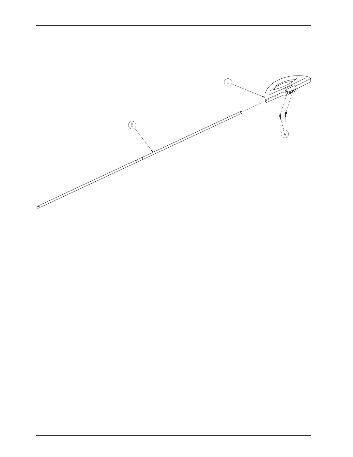
For Reference Only: 3006-260-340
Brake Shaft Assembly
Item Part No. Part Name Qty.
A 0004-270-000 Socket Head Cap Screw 2
B 3006-200-314 Brake Shaft 1
C 3006-260-325 Brake Pedal 1
Return To Table of Contents
100 300 6- 009 -102 REV C ww w.stryker.com
 Loading...