

READ AND SAVE THESE INSTRUCTIONS
INSTALLATION &
G-SERIES
G-SERIES SERVICE REFRIGERATED DISPLAY
CASES (SELF-CONTAINED & REMOTE UNITS)
PLEASE NOTE THE FOLLOWING:
1. YOUR SPECIFIC MODEL NUMBER IS LOCATED ON
THE SERIAL LABEL (USUALLY AT CASE REAR).
HOWEVER, LABEL LOCATIONS MAY VARY
DEPENDING UPON MODEL.
2. SEE SERIAL LABEL LOCATION & INFORMATION
SECTION IN MANUAL FOR SAMPLE LABELS.
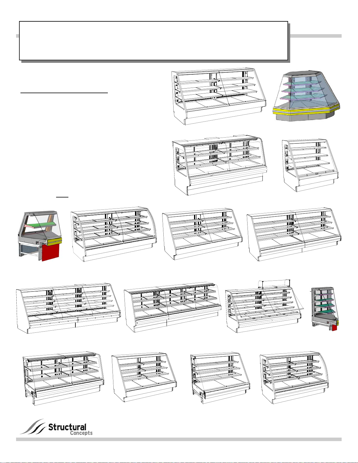
3. CASES SHOWN IN THIS MANUAL REFLECT FULL
& OPEN END PANELS / STRAIGHT OR ANGLED
BASES. YOURS MAY DIFFER.
4. NOT ALL MODELS COVERED BY THIS MANUAL
ARE SHOWN HERE. SEE “MODELS LISTED IN
THIS MANUAL...” SECTION IN THIS OPERATING
MANUAL FOR A FULL LIST OF MODELS COVERED
BY THIS MANUAL AND INFORMATION REGARDING
SPECIFIC CASE DIMENSIONS OF STANDARD
MODELS AND
CDRs.
OPERATING MANUAL
Model GHS8R - Straight Front Glass
GHSAC852R
GHSX952RLB - 90° Outer Wedge
PN 5-0172
GHS452RLB
GMDSNA4R.5773M
45° Inside Wedge
GHS1256RLB Straight Front Glass
GHS8R.4848D GHS5R.4985A
GHS8R.4845A Curved Front Glass
GHS6R.4845 - Straight Glass
Structural Concepts Corporation · 888 E. Porter Road · Muskegon, MI 49441
Phone: 231.798.8888 Fax: 231.798.4960 · www.structuralconcepts.com
GHS8R.4845A Straight Front Glass
GHS12R.4848F
GHS10R.4848B Straight Front Glass
GHS852RLB - Straight Glass
With Upper Acrylic Storage
GHS6R.4845 - Curved Glass
GHSN456RLB
45° Inside Wedge
I:\Oper Manual\Standard\G-Series_Service_Refrig_Oper_Manual_5-0172.pub
Rev R Date: 12.28.2013
TABLE OF CONTENTS
TABLE OF CONTENTS ………………………………………………………………………………………..
MODELS LISTED IN MANUAL (AND DETERMINING THEIR RESPECTIVE CASE DIMENSIONS)
OVERVIEW / TYPE / COMPLIANCE / WARNINGS / PRECAUTIONS / WIRING / PLUGS ..………….
INSTALLATION: REMOVAL FROM SKID, REMOVING LOWER FRONT PANELS ..……...…….…….
INSTALLATION: ADJUSTING FRONT PANELS / ADJOINING UNITS / GLASS SHELVING ………...
INSTALLATION: ELECTRICAL CONNECTIONS / LED DRIVER BOX …………………...……………..
INSTALLATION: FRONT FAN ACCESS ….………………………………………………………………….
INSTALLATION: FRAME SUPPORT RAILS / SEALING TO FLOOR / LOCKING CASTERS ………...
INSTALLATION: FRONT GLASS ALIGNMENT & ADJUSTMENT (CURVED & FLAT) ………………..
INSTALLATION: REFRIG. LINES / STUB-UPS / DRAINS / WIRING DIAGRAMS / VENTILATION ….
INSTALLATION: DISPLAY CASE START-UP ……………………………………………………………...
INSTALLATION: MODEL GHSAC852R - SCALE STAND & OUTLETS / THERMO-SIMPLE ALARM .
START-UP & OPERATION - THERMO-SIMPLE 2 (TS.2) DIGITAL THERMOMETER ALARM ...…….
DRAIN, HOSE AND BRACKET PLACEMENT ILLUSTRATIONS …………...…………..……….……….
MAINTENANCE FUNDAMENTALS - FLUORESCENT LIGHT FIXTURES ……………….……………..
MAINTENANCE FUNDAMENTALS - LED LIGHTS / BRACKETS / SHELVES ….……………………...
MAINTENANCE FUNDAMENTALS - DRAIN / TXV / REFRIGERATION LINES / SHUT-OFF VALVE
MAINTENANCE FUNDAMENTALS - REAR SLIDING DOORS / THERMOMETER …………………....
MAINTENANCE FUNDAMENTALS - HINGED REAR DOORS ………….………………………………..
MAINTENANCE FUNDAMENTALS - WEDGE UNITS: NON-ADJUSTABLE SHELVING ……………...
GENERAL CLEANING (TO BE PERFORMED BY STORE PERSONNEL) ………………..……...…….
TROUBLESHOOTING (TO BE PERFORMED BY STORE PERSONNEL) ..………..…….……….…….
GENERAL CLEANING (TO BE PERFORMED BY TRAINED SERVICE PROVIDERS ONLY) ………..
TROUBLESHOOTING (TO BE PERFORMED BY TRAINED SERVICE PROVIDERS ONLY) ………..
TROUBLESHOOTING - CONDENSING SYSTEM (BY TRAINED SERVICE PROVIDERS ONLY) …..
TROUBLESHOOTING - EVAPORATOR SYSTEM (BY TRAINED SERVICE PROVIDERS ONLY) ….
PREVENTIVE MAINTENANCE (TO BE PERFORMED BY TRAINED SERVICE PROVIDER)………..
SERIAL LABEL INFORMATION & LOCATION ..……………………………………...…....…………...…..
CAREL® CONTROLLER - PROGRAMMING THE INSTRUMENT….…………………………….……....
CAREL® CONTROLLER - USER INTERFACE, SUMMARY TABLES OF ALARMS & SIGNALS ...….
CAREL® CONTROLLER - Summary Table of Operating Parameters (After Programming Key) ……..
TECHNICAL SERVICE CONTACT INFORMATION & WARRANTY INFORMATION ...……….…........
2
3
4-5
6
7
8
9
10
11
12
13
14
15-16
17
18
19
20
21
22
23
24
25
26
27-29
30
31
32
33
34
35
36
37
2

MODELS LISTED IN THIS MANUAL (AND DETERMINING THEIR RESPECTIVE CASE DIMENSIONS)
DETERMINING YOUR MODEL AND ITS CASE DIMENSIONS:
Note 1. Your model number can be found on serial label (usually at case rear). However, serial
label placement can sometimes vary depending upon model. See SERIAL LABEL INFORMATION
& LOCATION section in this manual for serial label samples.
Note 2. Dimensions of most models can be found at www.structuralconcepts.com. Simply enter the
case model number into the Product Number Search box. Click the product specification link for
complete dimensions.
Note 3. If your specific model is not found, contact technical service (phone number is listed at
Technical Service section in this manual) for dimensions.
Note 4. CDRs (Customer Design Requests) are listed with a 4-digit suffix. Dimensions are very
similar to standard model (pre-suffix) dimensions.
THIS OPERATING MANUAL ENCOMPASSES THE FOLLOWING MODELS (AND/OR THEIR
RESPECTIVE CDRs): G-Series GHS5R.4985A, GHS6R.4845, GHS8R, GHS8R.4845A,
GHS8R.4848D, GHS452RLB, GHS452RLB.5575, GHS456RLB, GHS556RLB, GHS652RLB
GHS656RLB, GHS852RLB, GHS856RLB, GHS856RLB.5575B, GHS1052RLB, GHS1056RLB,
GHS10R.4985B, GHS12R.4848F, GHS1252RLB, GHS1256RLB, GHSAC452R, GHSAC652R,
GHSAC852R, GHSAC1052R, GHSAC1252R, GHSACS657R, GHSACS857R, GHSACS1257R,
GHSEH452RLB, GHSEH652RLB, GHSN456RLB, GHSX952RLB and GMDSNA4R.5773M
3
OVERVIEW / TYPE / COMPLIANCE / WARNINGS / PRECAUTIONS / WIRING / PLUGS - PAGE 1 of 2
OVERVIEW
These Structural Concepts merchandisers are
designed to merchandise packaged products at 41 °F
(5 °C) or less product temperatures (unless custom
cases with wire rack shelving).
Product must be pre-chilled to 41 °F (5 °C) or less
prior to being placed in merchandiser.
Cases should be installed and operated according to
this operating manual’s instructions to ensure proper
performance.
Improper use will void warranty.
TYPE 1 vs. TYPE 2 CONDITIONS
This unit is designed for the display of products in ambient
store conditions where temperatures and humidity are
maintained within a specific range.
For Type 1 Conditions (most cases): ambient
conditions are to be at 55% maximum humidity and
maximum temperatures of 75 °F (24 °C).
For Type 2 Conditions: ambient conditions are to be
at 60% maximum humidity and maximum
temperatures of 80 °F (27 °C).
If unsure if unit is designed for Type 1 or Type 2
conditions, see identifying label on your case.
Location varies, depending upon model.
COMPLIANCE
Performance issues when in violation of applicable
NEC, federal, state and local electrical and plumbing
codes are not covered by warranty.
See below compliance guideline.
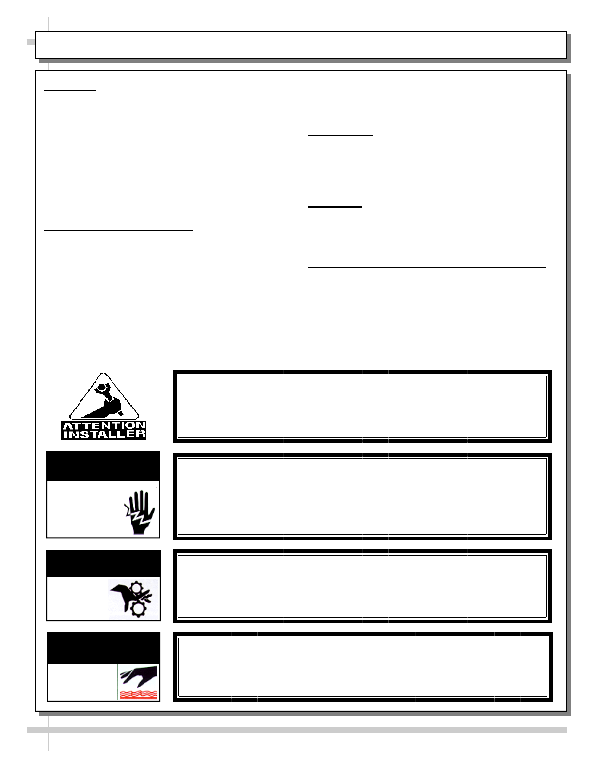
WARNINGS
This page contains important warnings to prevent
injury or death.
Please read carefully!
PRECAUTIONS, CORD/PLUG & WIRING DIAG RA MS
See next page for PRECAUTIONS, CORD/PLUG
and WIRING DIAGRAM information.
WARNING
ELECTRICAL
HAZARD
WARNING
KEEP
HANDS
WARNING
HOT
SURFACE
COMPLIANCE
This equipment MUST be installed in compliance with
all applicable NEC, federal, state and local
electrical and plumbing codes.
WARNING
Risk of electric shock. Disconnect power before servicing unit.
CAUTION! More than one source of electrical supply is
employed with units that have separate circuits.
Disconnect ALL ELECTRICAL SOURCES before servicing.
WARNING
Hazardous moving parts. Do not operate unit with covers removed.
Fan blades may be exposed when deck panel is removed.
Disconnect power before removing deck panel.
WARNING
Condensate Pan is Hot!
Electric condensate pan must be disconnected and allowed
to cool before cleaning or removing from case.
4
OVERVIEW / TYPE / COMPLIANCE / WARNINGS / PRECAUTIONS / WIRING / PLUGS - PAGE 2 of 2
PRECAUTIONS
Following are important precautions to prevent
damage to unit or merchandise.
Please read carefully!
See previous page for specifics on OVERVIEW,
CONDITION TYPE, COMPLIANCE and WARNINGS.
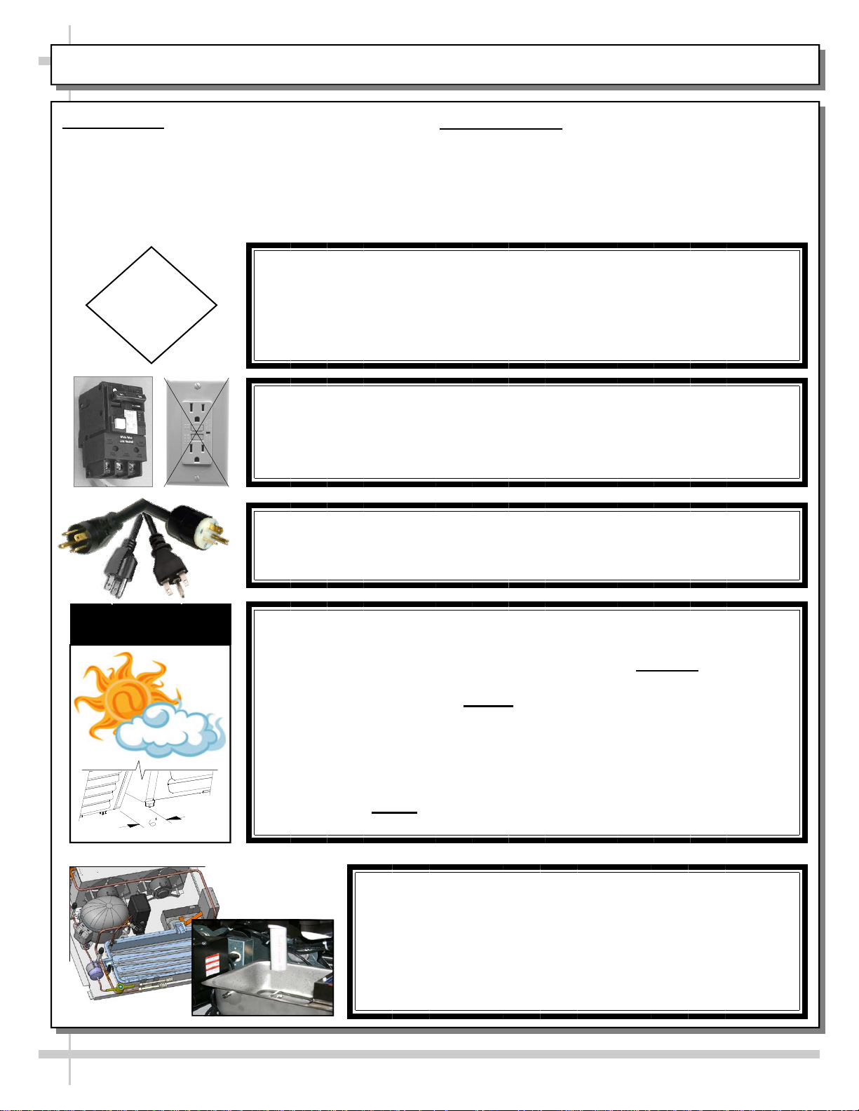
CAUTION! LAMP REPLACEMENT GUIDELINES
LED lamps reflect specific size, shape and overall design.
CAUTION
Any replacements must meet factory specifications.
Fluorescent lamps have been treated to resist breakage and
must be replaced with similarly treated lamps.
CAUTION! GFCI BREAKER USE REQUIREMENT
If N.E.C. (National Electric Code) or your local code
requires GFCI (Ground Fault Circuit Interrupter) protection,
you MUST use a GFCI breaker in lieu of a GFCI receptacle.
CAUTION! POWER CORD AND PLUG MAINTENANCE
Risk of electric shock. If cord or plug becomes damaged,
replace only with cord and plug of same type.
WIRING DIAGRAM
Each case has its own wiring diagram folded and in
its own packet.
Wiring diagram placement may vary; it may be
placed near ballast box, field wiring box, raceway
cover, or other related location.
CAUTION
CAUTION! ADVERSE CONDITIONS / SPACING ISSUES
Performance issues caused by adverse conditions are NOT warranted.
End panels must be tightly joined or kept at least 6-inches away from
any structure to prevent condensation.
Unit must be kept at least 15-feet from exterior doors, overhead HVAC
vents or any air curtain disruption to maintain proper temperatures.
Unit must not be exposed to direct sunlight or any heat source
(ovens, fryers, etc.).
Tile floors, low ceilings or small rooms increase noise level. Whisper
Cool compressor blankets or remote units resolve noise level issues.
Keep at least 8-inch clearance above unit for air discharge
(self-contained units only).
CAUTION! CHECK CONDENSATE PAN POSITION & PLUG
Water on flooring can cause extensive damage!
Before powering up unit, check and confirm that:
Condensate pan is DIRECTLY UNDER condensate drain.
Condensate overflow pan is connected and operational.
Condensate pan plug is securely plugged into receptacle.
5
INSTALLATION: REMOVAL FROM SKID, REMOVING VERTICAL LOWER FRONT PANELS
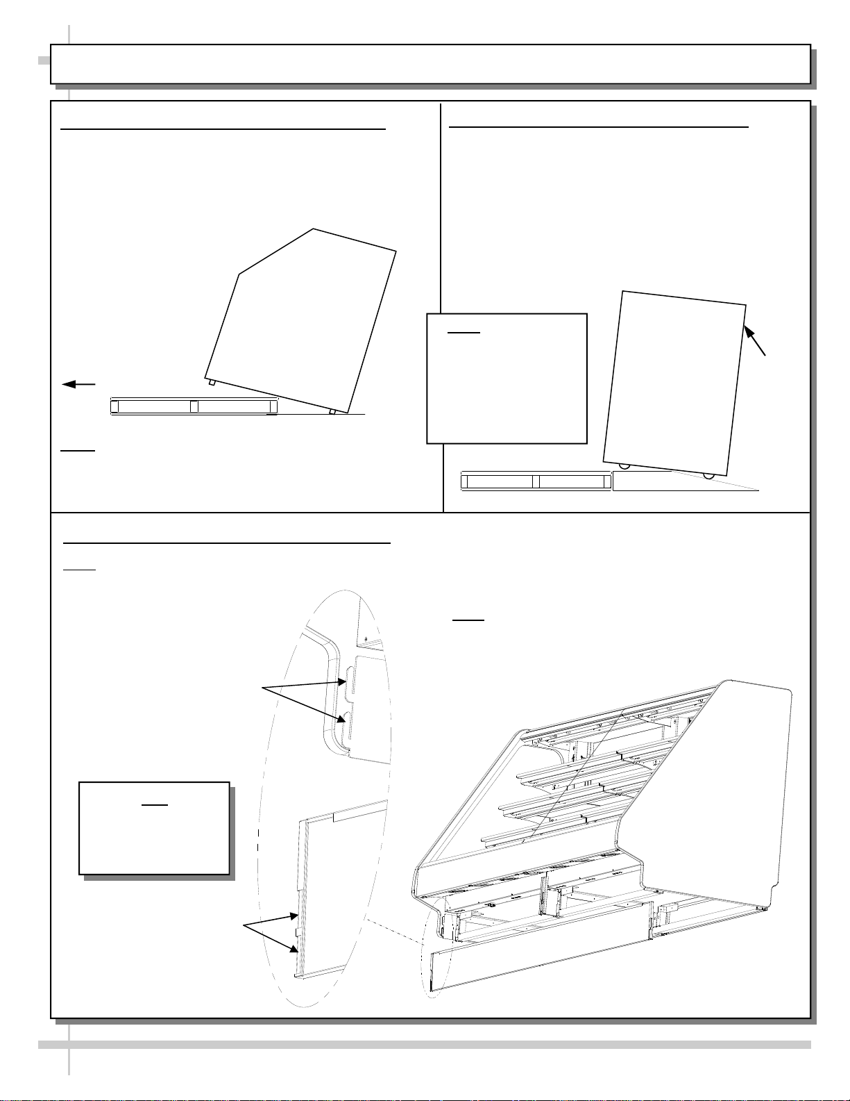
1. Remove From Skid (Rails or Levelers)
Remove shipping brace that may be securing
case to skid.
Support case to prevent tipping.
Caution! Frame Support Rails (or levelers) can
be damaged if case hits floor with heavy force!
Carefully slide unit to
rear of skid and tip
backward off skid.
Illustration may not
reflect every feature
or option of your
particular case.
Slide Skid Out
Note: Case can be repositioned with pallet truck
when front lower panel is removed. Blocking
may be necessary to obtain adequate height.
2. Remove Case From Skid (Casters)
Remove shipping brackets that may be securing
casters to skid
Place ramp up against skid (to allow case to
smoothly slide off from skid).
Maintain support of case at all times or center
of gravity may cause case to fall.
Unlock Casters. Roll unit to rear of skid.
Roll down ramp
and off from skid.
Note: Illustrations
shown reflect a
general outline of
sample cases and do
not reflect features or
options of your
particular model.
Ramp
Support
while
rolling
case
down
ramp.
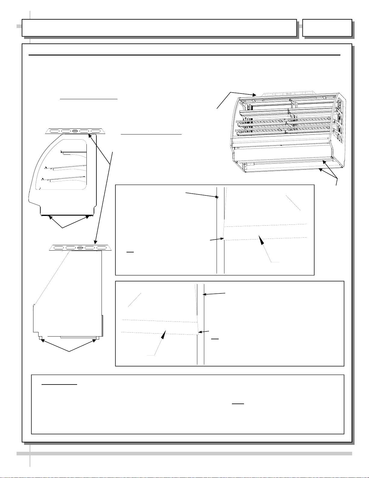
3. Removing Vertical Lower Front Panels
Note: No screw removal required: Simply lift lower front panel up (off hooks) and out (away from case).
Note: Illustration below reflects flat front glass
(optional). Your case may have curved front glass.
General slots/hooks design is the same.
Hooks For Lower
Front Panel
Note
Lower Front Panel
Removed & Reversed
For Illustrative
Purposes Only
Slots For Lower
Front Panel
6
View of Front Panel
(Removed & Reversed)
INSTALLATION: ADJUSTING FRONT PANELS / ADJOINING UNITS / GLASS SHELVING
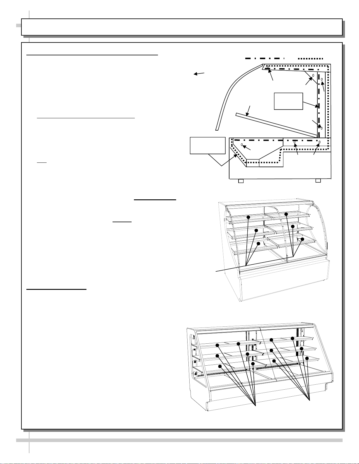
4. Bolting and Caulking Units Together
Follow these steps to assure a secure, level lineup.
A. Begin all lineups leveling from highest point of
floor.
B. After the ’first’ case is level, apply industrial grade
butyl caulk on non-visible areas (at case end).
Use industrial grade silicone sealant on visible
areas (at case end).
C. Form Two (2) Caulk/Sealant Lines
: (Sanitation
and Refrigeration). See illustration at mid-right for
outline of caulk/sealant lines.
D. Line up ‘second’ case bolt-hole to bolt-hole to
‘first’ case.
E. Using SCC-supplied bolts (found in hole locations
OR
in installation packet), insert bolts in bolt hole
locations (shown at top-right). You may need to
remove decking to access lower bolt holes.
F. Caution! Front of cases MUST be flush with each
other! After leveling, all cases to be same height.
G. Using SCC-supplied nuts & bolts, lightly tighten
each of the 5 to 8 bolts in a cross-wise pattern.
Work your way around the pattern, tightening
more firmly at each pass. Do not
firmly tighten
one bolt and then start on the next!
H. After the cases are bolted together, level the
‘second’ case. Repeat this process for each case
to be adjoined.
I. After all lined-up cases are level, seal all seams
with industrial grade silicone sealant.
See illustration at top-right.
5. Glass Shelving
Certain models have glass shelving. Glass shelving
will be packed separately for shipment.
Caution! Carefully remove from packaging.
Grasp firmly and carefully install.
Caution! Check that plastic edging is intact
before placing glass shelving onto brackets!
Plastic edging must NOT be removed from glass
shelves. Contact Structural Concepts for
replacement edging (see TECHNICAL
SERVICE CONTACT INFORMATION section).
Check that glass shelving is in proper position
before placing product in case.
See illustrations at mid and lower-right showing
both curved and flat front glass (optional).
Approximate hole
locations pointed
at with arrows
( ) for bolting
units together.
Refrigeration
Bead
Glass
Shelves
Sanitation Bead Refrigeration Bead
Deck
Sanitation
Bead
7
Glass
Shelves
Glass
Shelves

INSTALLATION: ELECTRICAL CONNECTIONS / BALLAST BOX (or OPTIONAL LED DRIVER BOX)
6. Electrical Connections
Front Ballast Box or LED Drive Box (Optional)
Remove front panel. See INSTALLATION:
REMOVAL FROM SKID, REMOVING VERTICAL
LOWER FRONT PANELS section in this manual for
instructions.
Stub-up connections are in ballast box.
Remove ballast box / LED driver box cover.
Note: Illustration below reflects flat front glass
(optional). Your case may have curved front glass.
Electrical connection/layout is the same for both.
Knockouts are on the underside of ballast box /
LED driver box making electrical connections.
Voltage rating is on serial label at case rear.
Note: Wiring process must be performed by
certified electrician only.
Fluorescent
Light Ballasts
Wire
Route
PBV
LED
Driver
(Optional)
Terminal
Strip
Ballast Box /
LED Driver Box
8
INSTALLATION: FRONT FAN ACCESS
7. Front Fan Access
Front Ballast Box
Remove screws along outer area of case.
Remove screws along inner area of case.
Drop Front Fan panel down.
Remove screws along
Front Fan
Panel
Repair/replace fans.
Replace in reverse order it was removed.
Voltage rating is on serial label at case rear.
Note: Wiring process must be performed by
certified electrician only.
outer area of case
Front Fan
Panel
Remove screws along
inner area of case
9
INSTALLATION: FRAME SUPPORT RAILS / SEALING TO FLOOR / LOCKING CASTERS
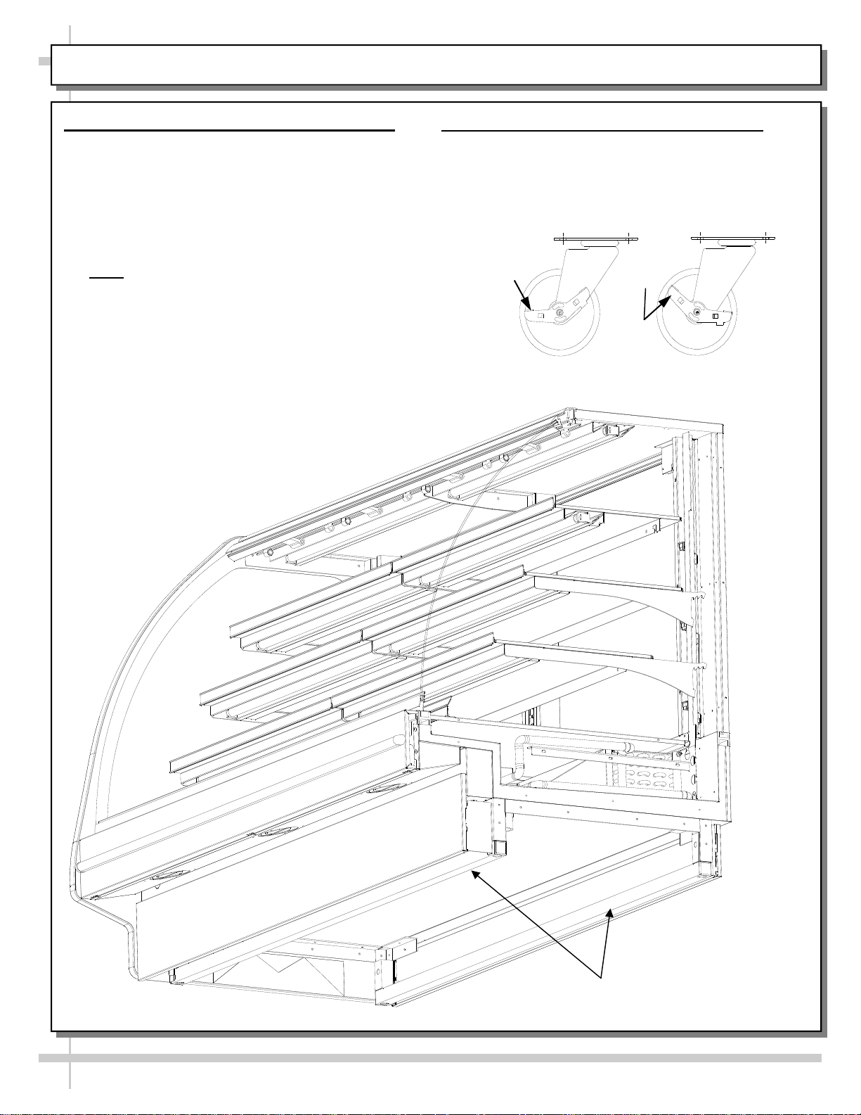
8. Cases With Frame Support Rails: Shim
Illustration below shows case with frame support
rails. End panel has been removed for
illustrative purposes only.
Shims will be provided with all cases that have
frame support rails.
Use shims to level case.
See illustration below.
Note: After case is in position, it must be
sealed to floor to prevent entry or leakage of
liquid or moisture.
9. Cases With Casters: Lock and Unlock
To lock casters, press down on lever.
To unlock casters, pull lever up.
See illustration below.
d
e
k
c
o
L
d
e
k
c
o
l
n
U
10
Frame Support
Rails
INSTALLATION: FRONT GLASS ALIGNMENT & ADJUSTMENT - RAILS / LEVELERS
T
10. Front Glass Alignment & Adjustment via Rails / Levelers (For Curved / Flat Front Glass)
Proper alignment of the front glass is important to create and maintain a seal inside the case.
Improper alignment can cause air leaks compromising the environment inside the case and create condensation.
Follow the five steps listed below to assure proper front glass alignment.
5-6563
1. Side-to-Side Leveling
(parallel to front glass). Level the case by inserting shims under
the rails (or, for levelers, rotating either clockwise or
counter-clockwise). Follow steps 3 and 4 below for specifics.
Case with Curved
Front Glass
Rails or Levelers
: Place a level on top of display case
2. Front-to-Back Leveling
Place a level on top of case,
perpendicular to the front glass.
Raise or lower either side of case by
shimming under the rails or adjusting
levelers (following steps 3 & 4 below).
Double-check the side-to-side level.
END PANEL
3. If FRONT-LEFT CORNER is
hitting it), insert shims at the
BACK LEFT CORNER of case.
Or
, for leveler system, adjust
levelers at the BACK LEFT
CORNER of case DOWNWARD
PANEL
too close to end panel (or
:
FRON
GLASS
Rails
Shown
LIFT
FRONT
Case with Flat
Front Glass
Rails or Levelers
5. Verification:
After inserting shims (or adjusting levelers), open and shut the front glass.
Verify (again) that front glass is properly aligned at left-hand and right-hand side of the case.
If not, repeat the shimming procedure (or leveler adjustment) until the front glass is properly
LIFT
GLASS
END PANEL
PANEL
4. If FRONT-RIGHT CORNER is too close
to end panel (or hitting it), insert shims at
the BACK RIGHT CORNER of case.
Or
, for leveler system, adjust levelers at the
BACK RIGHT CORNER of case
DOWNWARD.
aligned along both sides of the case.
11
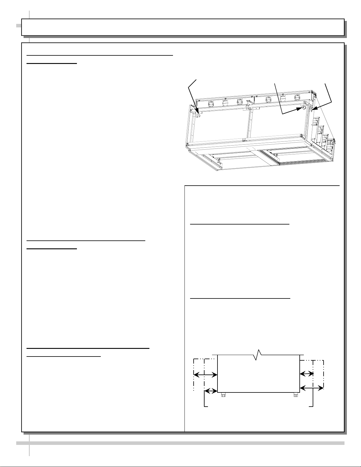
INSTALLATION: REFRIG. LINES / STUB-UPS / DRAINS / WIRING DIAGRAMS / VENTILATION
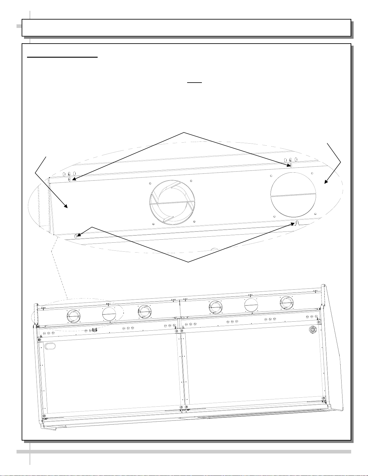
11. Refrigeration Line Stub-Up Connections
(Remote Units)
Remove front panel.
Refrigerant stub-up access opening is at the
front on the left hand side of the base (see
illustration at top-right).
Stub-up connections are accessed from inside
the case.
Remove interior decks.
Remove fan shroud assembly.
Line connections are in the tub front, on the left
hand side
Remove foam material from the entry hole
provided in the tub drain trough.
Route refrigerant lines through access hole.
Run case-to-case connections through
cutouts in base.
Sweat the high and low pressure
Refrigeration
Line Stub-Ups
Access
Drain Stub-Up (may be
at case center in
extended length cases)
Cutout
connections.
Fill access hole with suitable filler to insure
watertight integrity of tub.
Illustration at top-right may not reflect every
feature or option of your particular case.
12. Refrigeration Drain Connection
(Remote Units)
Depending upon drain access needs, either front
or rear panel may be removed to gain access to
drain stub-up.
1.5” male PVC stub-up connection is under the
case on the right hand side.
Drain stub-up may be at case center in extended
length cases.
Connect tub drain to floor drain. Maintain
1/4”-fall per foot to provide proper drainage.
Illustration at top-right may not reflect every
feature or option of your particular case.
13. Condensate Pan / Drain Position
(Self-Contained Units)
Remove the Rear Panel by lifting up & out.
Slide the Condenser Unit out from case.
Condenser Unit access is now available.
Insure that the condensate pan is installed under
the PVC condensate drain trap.
Insure that the condensate pan is plugged into
the receptacle inside base.
Lower rear panel back into place.
See Drain, Hose and Bracket Placement
section in Operating Manual for details.
14. Electrical Wiring Diagram
Each case has its own wiring diagram
folded and in its own packet.
Wiring diagram placement may vary; it may
be placed near condenser fan cover,
ballast box, raceway cover, or other related
location.
15. Ventilation and Clearance
Self-Contained refrigerated cases must
maintain airflow clearance of 6” (minimum) to
12” (recommended) at front and rear.
Restriction of air can void warranty.
Illustration below may not reflect every feature
or option of your particular case.
Check air grilles for obstructions.
Maintain airflow clearance of 6” (min.)
to 12” (recommended) at front & rear.
12
 Loading...