

Page 1
Riva 76 Fan Kit
Installation Instructions
Product Codes: RV76FK (For use with RVF76)
RV76BFK (For use with RVF76B)
For use in GB, IE (Great Britain and Eire)
IMPORTANT
For use with 230v 50 - 60Hz electricity supply only.
Please read these instructions carefully and in conjunction with the appropriate Riva Installation and User instructions.
Care must be taken when handling the stove to avoid injury or damage to the stove.
They will be needed when maintenance or servicing is required.
THIS APPLIANCE MUST BE EARTHED
PM214-Issue 1 (Sept 2007)
Page 2
INSTALLATION INSTRUCTIONS
PACKING LIST
• Riva Fan Kit
TOOLS REQUIRED
• 2.5mm hex key supplied with Riva Cassette
POWER SUPPLY
A 230v 50 - 60Hz supply is required.
THIS APPLIANCE MUST BE EARTHED
Provision for the power supply should be made
before installing the product, with connections
made by a qualified electrician via a 3 Amp
supply and complying with any local and
national regulations and guidelines
INSTALLATION INSTRUCTIONS
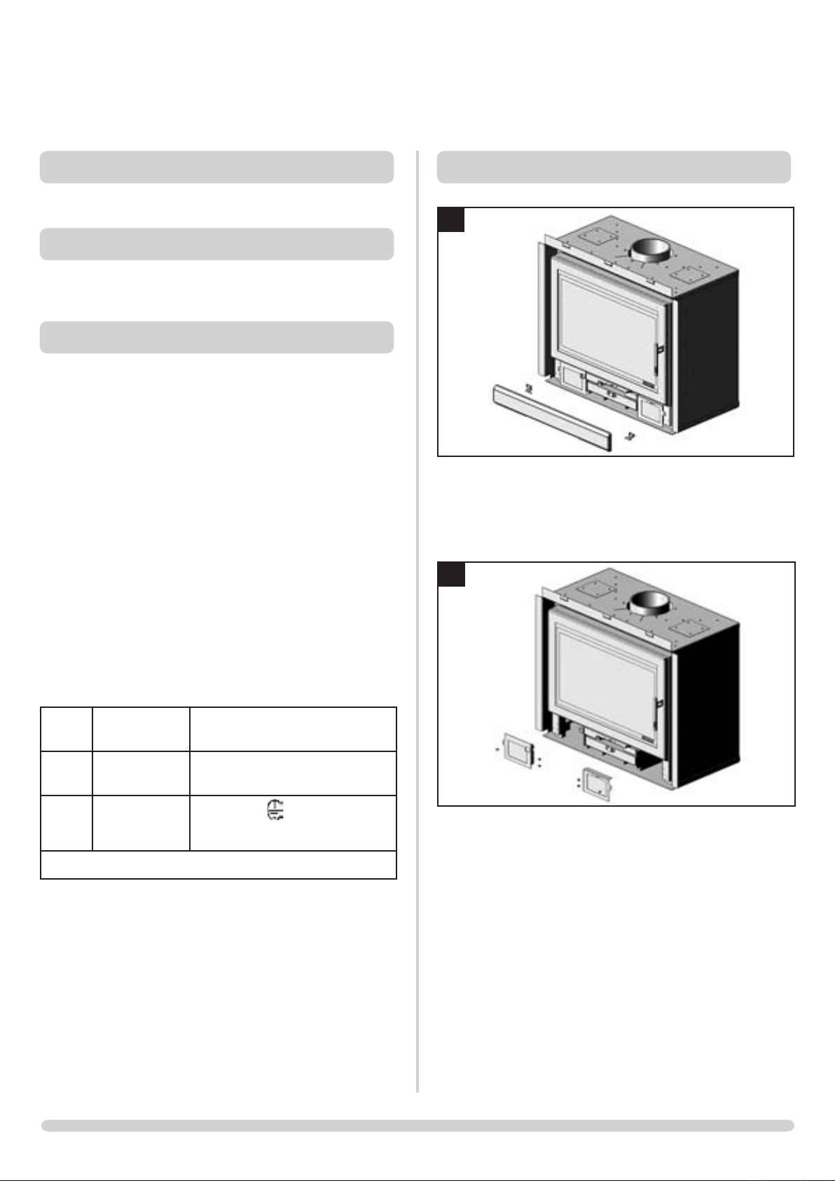
1
PR7587
Remove ash cover and hinges, diagram 1
Also see Riva MF Cassette Installation Instructions
(PM183) - Section 2. Ash pan door removal (Page
8)
If the electricity supply cable is damaged do not
use the appliance until it has been replaced. For
safety reasons the replacement should be carried
out by a Stovax servicing agent or a similarly
competent electrician.
Live
wire
Neutral
wire
Earth
wire
Brown Terminal Marked L / coloured
RED
Blue
Green and
yellow stripes
230v 50 - 60Hz supply is required
Terminal Marked N / coloured
BLACK
Marked E / / colour GREEN
or GREEN & YELLOW
WARNING – FAILURE TO CONNECT THE
WIRES CORRECTLY COULD PUT PEOPLE AT
RISK FROM ELECTRIC SHOCK OR FIRE.
2
PR7588
Remove fan fascias. Use the 2.5mm hex key
supplied. Keep left hand fascia, diagram 2
2
Page 3

INSTALLATION INSTRUCTIONS
3
Button screws
Wiring omitted
for clarity
PR7589
Slide fan chassis in to Riva 76 as shown and fix
using existing button screws, diagram 3
4
6
PR7600
Finish installation
OPERATING INSTRUCTIONS
7
Button screws
PR7590
Refit left hand fascia, diagram 4
5
PR7591
Refit the ash cover and hinges, diagram 5
3 way switch
Speed control
PR7610
The fan is controlled by a 3 way switch,
diagram 7
Position 0 - Off
Position I - Automatic. The fan will switch
on once the cassette reaches working
temperature
Position II - Manual Override. This switches
the fan on automatically
Speed Control - This varies the fan speed
when the 3 way switch is in position I or II
3
Page 4

Stovax Ltd, Falcon Road, Sowton Industrial Estate, Exeter, Devon, England EX2 7LF
Tel: (01392) 474011 Fax: (01392) 219932 E-mail: info@stovax.com www.stovax.com
 Loading...