


Logic Hotbox & Convector Fire
With upgradable control valve
Instructions for Use,
Installation and Servicing
For use in GB, IE (Great Britain and Eire)
This appliance has been certified for use in countries other than those stated. To install this appliance in these countries, it is essential to obtain the translated instructions and in some cases the appliance will require modification. Contact Gazco for further information.
IMPORTANT
The chimney must be swept before installation. Do not attempt to burn rubbish on this fire. This fire has a naked flame. A suitable guard should be used for the protection of young children, the elderly or infirm.
This appliance is intended for decorative purposes only.
Please read these instructions carefully and keep them in a safe place.
They will be needed when servicing the fire.
The commissioning sheet on page 3 MUST be completed by the Installer.

Covering the following models
Hotbox |
Convector |
8306PBUC |
8308PBUC |
P80306PBUC |
P8308PBUC |
8306MCUC |
8308MCUC |
P8306MCUC |
P8308MCUC |
CONTENTS
|
PAGE |
APPLIANCE COMMISSIONING CHECKLIST |
3 |
USER INSTRUCTIONS |
4 |
INSTALLATION INSTRUCTIONS |
8 |
Technical Specifications |
8 |
Site Requirements |
10 |
Installation |
11 |
Commisioning |
17 |
SERVICING INSTRUCTIONS |
18 |
Servicing Requirements |
18 |
Fault Finding |
19 |
How to replace parts |
21 |
Basic spare parts list |
23 |
2
APPLIANCE COMMISSIONING CHECKLIST
IMPORTANT NOTICE
Explain the operation of the appliance to the end user, hand the completed instructions to them for safe keeping, as the information will be required when making any guaranteed claims.
DEALER AND INSTALLER INFORMATION
Gas Type . . . . . . . . . . . . . . . . . . . . . . . . . . . . . . . . . . . . . . . . . . . . . . . . . . . . . . . . . . . . . . . . . . .
3
USER INSTRUCTIONS
1.GENERAL
1.1Installation and servicing must only be carried out by a competent person.
1.2In all correspondence, please quote the appliance type and serial number, which can be found on the databadge adjacent to the control knob.
1.3Ensure that curtains are not positioned above the fire, and that there is a 300mm minimum clearance between the sides of the fire and any curtains.
1.4This product is guaranteed for 12 months from the date of installation, as set out in the terms and conditions of sale between Gazco and your local Gazco dealer. Please consult with your local Gazco dealer if you have any questions. In all correspondence always quote the Model Number and
Serial Number.
1.5Parts of this appliance become hot during normal use. It is therefore recommended that a suitable fire guard be used for protection of young children and the infirm.
2.LIGHTING THE FIRE
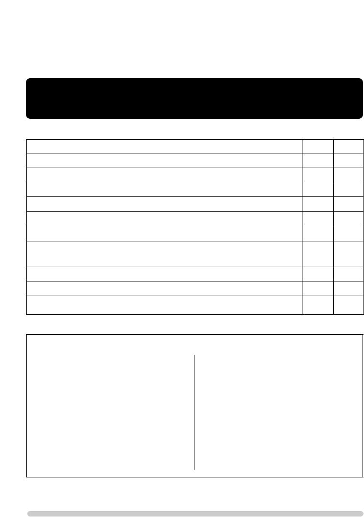
2.1Locate the control valve on the appliance. There are two control knobs on the valve, the right hand knob controls the pilot ignition and the left hand knob controls the main burner.
2.2If your appliance has already been upgraded to battery remote control, please refer to the instructions provided with the upgrade to operate the remote control. The following instructions will work for either situation.
1
2.3Ensure that the left-hand control knob is pointing to off ( ).
).
2.4Ensure that the right hand control knob is pointing to off ( ).
).
2.5Press in the right hand control knob and rotate it anti-clockwise until a click is heard (keep pressing in) and the knob is pointing to pilot ( ). The pilot should now light. If the pilot has not lit, repeat the procedure until it does.
2.6Keep the control knob pressed for 10 seconds and then release it, the pilot should stay alight. If the pilot goes out, repeat the procedures until it does.
2.7If the pilot will not light after repeated attempts, contact the retailer or installer from whom the appliance was purchased.
2.8Turn the right hand control to point to main burner ( ). The appliance can now be controlled using the left hand control knob.
2.9 Turn the left hand control knob to point to low fire ( ), the main burner will light on low. The burner can now be controlled between low and high settings. Turn the control
knob anticlockwise increase the flame height and clockwise to decrease the flame height.
THE YELLOW FLAMES WILL APPEAR WHEN THE FIRE HAS GAINED SUFFICIENT HEAT - TYPICALLY 10 TO 20 MINUTES.
3.TURNING THE FIRE OFF
3.1To turn the fire off, locate the control valve, turn the left-hand control knob until it points to off ( ). The main burner will go out leaving the pilot burning.
3.2To turn the pilot off, locate the control valve, turn the right hand control knob until it points to off ( ), the pilot will go out.
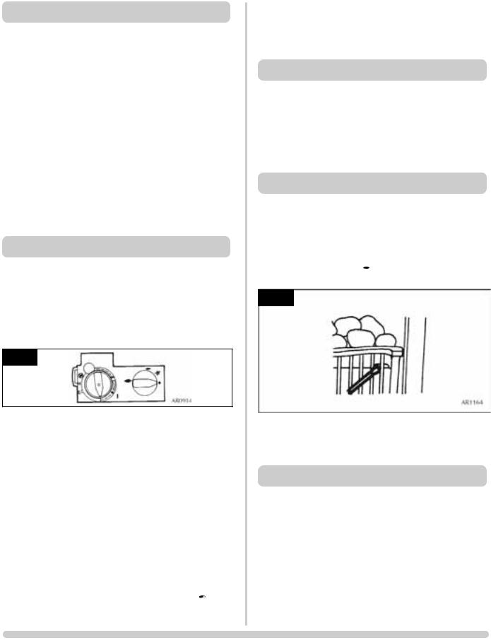
4.LIGHTING THE FIRE WITH A MATCH
If the pilot does not ignite as described in Section 2, please consult your GAZCO dealer to rectify the problem. However, the appliance may be lit as a temporary measure using the following procedure:
4.1Press in the right hand control knob and rotate it anticlockwise until a click is heard (keep pressing in) and the
knob is pointing to pilot ( ), apply a lighted match to the pilot hood, see diagram 2
2
4.2When the pilot is alight, extinguish the match and continue to depress for 5 to 10 seconds.
4.3The fire may now be controlled as previously described.
5.1Your fire is fitted with a control valve that can easily be upgraded to battery powered remote control. This upgrade can be fitted by anyone capable of simple DIY jobs and requires no special training This upgrade can be obtained
through your local Gazco |
. |
5.2STANDARD REMOTE CONTROL This remote control can control the fire after the pilot has been lit. It can turn the
main burner on and regulate it from low through to high and back again. It can turn the burner off leaving the pilot burning GAZCO PART NUMBER 8455.
5.3 IMPORTANT - there is a thermostatic version of the upgrade but this is NOT SUITABLE open flame fires like the Logic.
4

USER INSTRUCTIONS
6.1Remove the ceramic coals or pebblesand place on a dry, clean surface. Remove the fuelbed and the burner cover gasket.
6.2Clean the burner and tray assembly using a vacuum cleaner with soft brush attachment, ensure all debris is removed from the burner ports.
6.3Replace the ceramics by referring to section 7.
7. ARRANGEMENT OF FUEL BED
COMPONENTS
NOTE: CERAMIC PARTS ARE FRAGILE. THE SIDE AND REAR PANELS ARE REVERSIBLE. ONE SIDE IS PLAIN, THE OTHER SIDE IS REEDED. ASK THE CUSTOMER WHICH SIDE IS PREFERRED AT THIS STAGE.
ONLY USE THE CORRECT TYPE AND QUANTITY OF CERAMIC COMPONENTS. POINTS 7.1 TO 7.5 ARE COMMON TO ALL FUEL TYPES AND LAYOUTS.
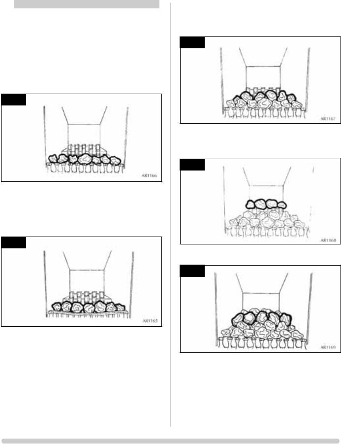
7.1Position the burner cover gasket on the burner skin ensuring the holes align with the ports. Take care as the front left-hand hole is offset compared to the others.
See diagram 3, arrow A.
3
7.2Position the flame baffle centrally on the tray and ensure the stepped lower edge engages against the rear edge of the burner skin. See diagram 4.
4
7.3Place the rear panel against the rear of the box and slide the side panels on either side of the flame baffle. Ensure they locate in the brackets at the top of the firebox. DO NOT SLIDE THEM ALL THE WAY BACK. See diagram 5.
5
7.4Locate the top panel on top of the rear and side panels. Finally push the sides fully towards the rear panel. This will retain the top panel. See diagram 6.
6
7.5Place the front coal centrally in the channel at the front of the tray. See diagram 7. The relationship between the front coal and flame baffle is shown in diagram 7.
7
5
USER INSTRUCTIONS
COAL LAYOUT
NOTE: THERE ARE TWO LARGE COALS IN A BAG INSIDE THE MAIN BAG. THESE ARE ONLY TO BE USED WHEN A CURVED FRONT SUCH AS THE HOLYROOD AND RICHMOND ARE USED. DO NOT USE THE TWO LARGE COALS WHEN USING A FLAT FRONTED FRAME.
A) FRONT ROW COAL LAYOUT USING FLAT FIRE FRONTS
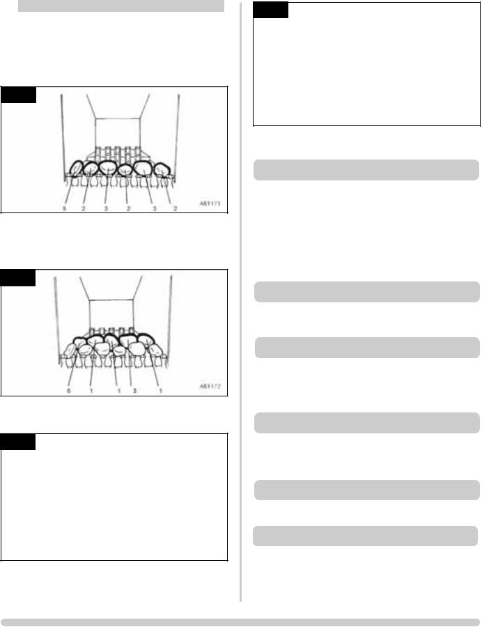
7.6The front row is the only difference in coal layout. Place one large coal centrally on the front coal resting against
the frame. Then place three small coals either side. See diagram 8.
8
B) FRONT ROW COAL LAYOUT USING CURVED FIRE FRONTS.
7.7Place three large coals resting on top of the front coal and against the front of the frame, then place two small coals either side of the large ones. See diagram 9
9
C)COAL LAYOUT CONTINUED FROM FRONT ROW
7.7Place four large coals behind the first row and one small coal either end resting up against the side panels.
See diagram 10
10
7.8Place one small coal either side on top of the flame baffle in each rear corner. Then place two large coals in between the two small coals. These coals should touch the rear panel.
See diagram 11.
11
7.9Finally place five large coals between the second and rear row of coals. See diagram 12.
12
6
USER INSTRUCTIONS
PEBBLE LAYOUT - CURVED AND FLAT FRONTS
7.12ALL THE PEBBLES HAVE AN IDENTIFICATION ON THE UNDERSIDE. ENSURE THE PEBBLES ARE PLACED ONLY IN THEIR CORRECT POSITIONS.
7.13Place the first row of pebbles on top of the front coal resting against the frame front. All the identifications are placed face down so they cannot be seen. See diagram 13.
13
7.14Working from the outside of the appliance, place the second row of pebbles against the rear of the first row. Note the orientation of each pebble, as this is important to the performance of the fire. See diagram 14.
14
7.15Place the rear row of pebbles on top of the flame baffle, these must touch the rear panel. See diagram 15.
15
2 |
2 |
4 |
5 |
|
|
|
AR1173 |
||||
|
|
|
|
|
|
|
|
|
|
|
|
7.16Place the remaining five pebbles between the second and rear rows. See diagram 16.
16
6 |
5 |
4 |
5 |
2 |
|
|
|
AR1174 |
|||||
|
|
|
|
|
|
|
|
|
|
|
|
|
|
8. OXYGEN DEPLETION SENSOR
9.FLAME FAILURE DEVICE
10.‘RUNNING IN’
12.VENTILATION
13.INSTALLATION DETAILS
13.1To assist in any future correspondence, your installer should have completed this commissioning sheet, this records, the essential installation details of the appliance. In all correspondence always quote the Model Number and Serial Number.
7

INSTALLATION INSTRUCTIONS
TECHNICAL SPECIFICATION
Covering the following models
Hotbox Convector
8306PBUC 8308PBUC P80306PBUC P8308PBUC 8306MCUC 8308MCUC P8306MCUC P8308MCUC
GAS CATEGORY |
|
|
|
12h |
|
|
|
13+ |
||
|
|
|
|
|
Natural |
|
|
Butane |
|
Propane |
Gas Type |
|
|
|
G20 |
|
|
G30 |
|
G31 |
|
Working Pressure |
|
|
|
20 mb |
|
|
29 mb |
|
37 mb |
|
Gross Input kW |
|
High |
|
6.7 |
|
6.7 |
|
6.7 |
||
|
|
Low |
|
3.0 |
|
3.0 |
|
3.0 |
||
Gas Rate m3/hr |
|
High |
|
0.64 |
|
0.192 |
|
0.252 |
||
|
|
Low |
|
0.29 |
|
0.086 |
|
0.113 |
||
Nox Class |
|
|
|
1 |
|
|
|
1 |
||
Injector size |
|
|
|
400 |
|
|
|
180 |
||
Aeration Size |
|
|
|
6x15 |
|
|
6x5 Rear |
|||
|
|
|
|
|
|
|
|
|||
|
|
|
|
|
23x15 Front |
|||||
|
|
|
|
|
|
|
|
|||
Min flue size |
|
|
|
|
|
5” diameter |
|
|
||
Min Flue size - Pre cast |
|
|
|
90mm x 183 mm (16,500mm2 min) |
||||||
Min flue specifacation |
|
|
|
|
T160 / N2 / 0 /D / 1 |
|||||
Gas Inlet |
|
|
|
|
|
|
8mm |
|
|
|
Weight (Gross) |
|
|
|
|
|
|
19Kg |
|
|
|
|
|
|
|
APPLICABLE FRONTS |
|
|
||||
|
|
|
|
|
|
|
|
|||
FRONT |
|
|
|
HOTBOX |
|
|
CONVECTOR |
|||
|
|
|
|
|
|
|
|
|
||
DESIGNIO |
|
|
|
8251MA |
|
|
|
8251MA |
||
|
|
|
|
|
|
|
||||
EVOLUTION |
|
|
8255MB, 8255BS |
|
|
8257MB, 8257BS |
||||
|
|
|
|
|
|
|
|
|
||
|
|
|
|
8391 |
|
|
|
8391 |
||
HOLYROOD |
|
|
8397 |
|
|
|
8397 |
|||
|
|
|
|
8150 |
|
|
|
8150 |
||
|
|
|
|
|
|
|
|
|
||
INFINITI |
|
|
|
8249BS |
|
|
|
8249BS |
||
|
|
|
|
|
|
|
|
|
||
PROGRESS |
|
|
|
8253BS |
|
|
|
8253BS |
||
|
|
|
|
|
|
|
|
|
||
RICHMOND |
|
|
|
N/A |
|
|
|
8678 |
||
|
|
|
|
|
|
|||||
SPANISH |
|
|
8382, 8385 |
|
|
8382, 8385 |
||||
|
|
|
|
8388, 8153 |
|
8388, 8153 |
||||
|
|
|
|
|
|
|
||||
VICTORIAN |
|
|
|
N/A |
|
|
4262, 4263 |
|||
CONVECTOR |
|
|
|
|
|
|
|
|
|
|
|
|
|
|
|
|
|
||||
ART NOUVEAU |
|
|
|
N/A |
|
|
4264, 4265 |
|||
CONVECTOR |
|
|
|
|
|
|
|
|
|
|
|
|
|
|
|
|
|
||||
COMBINATION |
|
|
|
N/A |
|
|
4362, 4363 |
|||
|
|
|
|
|
|
|
|
|
|
|
8
 Loading...