

Riva Plus Fan Kits
Riva Small, Midi, Medium & Large
Installation & Users Instructions
For use in GB, IE (Great Britain and Eire)
This appliance has been certified for use in countries other than those stated. To install this appliance in these countries, it is essential to obtain the translated
instructions and in some cases the appliance will require modification. Contact Stovax for further information.
IMPORTANT
For use with 230v 50 - 60Hz electricity supply only.
Please read these instructions carefully and in conjunction with the appropriate Riva Installation and User instructions.
Care must be taken when handling the stove to avoid injury or damage to the stove.
They will be needed when maintenance or servicing is required.
THIS APPLIANCE MUST BE EARTHED
PM256 -Issue 1 (September 2008)
COVERING THE FOLLOWING MODELS:
Appliance Kit Part No.
Riva Plus Small RVP0006
Riva Plus Midi RVP0006
Riva Plus Medium RVP0009
Riva Plus Large RVP0009
USER INSTRUCTIONS 2
Operating Instructions 2
INSTALLATION INSTRUCTIONS 3
General 3
Packing list 3
Tool required 3
Power supply 3
Installation
\
COMMISSIONING 3
USER INSTRUCTIONS
Installation of a fan kit helps circulate combustion air from the Riva appliance. This aids convected heat which results in
greater delivery into the room.
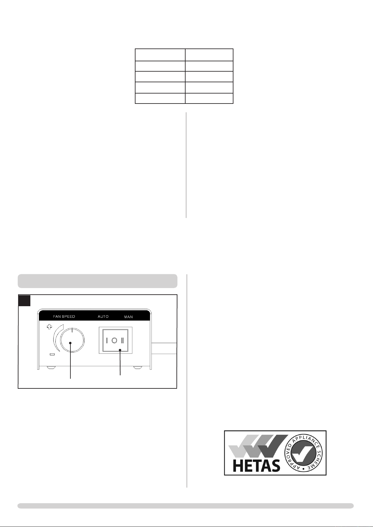
OPERATING INSTRUCTIONS RIVA PLUS
1
Speed control
The fan is controlled by a 3 way switch on the right hand side
of the cassette, diagram 1
Position 0 - Off. Fan does not operate
Position I - Automatic. The fan will switch on once the
cassette reaches working temperature
Position II - Manual Override. This switches the fan on
irrespective of the cassette temperature.
3 way switch
PR8179
Speed Control - This varies the fan speed when the 3 way
switch is in position I or II
This appliance has been approved by HETAS Ltd.
2

INSTALLATION INSTRUCTIONS
GENERAL
This fan system may be supplied in kit form and installed
in accordance with these instructions OR it may have
been factory fitted.
PACKING LIST
• Riva Plus Fan Kit
TOOLS REQUIRED
• 10mm A/F Spanner
POWER SUPPLY
A 230v 50 - 60Hz supply is required.
THIS APPLIANCE MUST BE EARTHED
Provision for the power supply should be made before
installing the product, with connections made by a
qualified electrician via a 3 Amp supply and complying
with any local and national regulations and guidelines
INSTALLATION
1
Velcro Pads
PR8179
M6 Screws
PR8178
1.1 • Position Fan kit as shown, diagram 1
• Attach using M6 Nuts supplied
• Secure control box in a convenient place using the self
adhesive Velcro pads supplied
• The appliance must be protect by a 3 amp fuse
• The electrical connection must allow for disconnection
• Use heat resistant cable
If the electricity supply cable is damaged do not use the
appliance until it has been replaced. For safety reasons the
replacement should be carried out by a Stovax servicing
agent or a similarly competent electrician.
Live
wire
Neutral
wire
Earth
wire
WARNING – FAILURE TO CONNECT THE WIRES CORRECTLY
COULD PUT PEOPLE AT RISK FROM ELECTRIC SHOCK OR
FIRE.
Brown Terminal Marked L / coloured RED
Blue
Green and
yellow stripes
230v 50 - 60Hz supply is required
Terminal Marked N / coloured
BLACK
Marked E / / colour GREEN or
GREEN & YELLOW
COMMISSIONING
1
Speed control
1. Check operation of fan kit
2. Explain the use of all the controls to the customer
3. Store these instructions with the ones supplied with the cassette
3 way switch
PR8179
3

Stovax Ltd, Falcon Road, Sowton Industrial Estate, Exeter, Devon, England EX2 7LF
Tel: (01392) 474011 Fax: (01392) 219932 E-mail: info@stovax.com www.stovax.com
 Loading...