

Page 1

Model VB50
OPERATORS MANUAL
Manual No. 513805
Page 2

2
Dear customer,
we congratulate you for choosing a high quality product
which will surely satisfy your expectations.
With our thanks for choosing us,
we kindly invite you to examine the present operating
instructions manual before operating your new device.
SUMMARY
1 TEST AND LIABILITY ............................................. 3
2 ENVIRONMENTAL CONDITIONS .......................... 3
3 GENERAL SAFETY NOTES .................................. 3
4 DEFINITION OF SAFETY TERMS ......................... 4
13 INSTALLATION ..................................................... 11
13.1 Placing and check of the parts ...................... 11
13.2 Machine’s parts reassembling ........................11
13.3 Electric connection ....................................... 12
13.4 Installing permanent wiring ............................ 13
13.5 Connection to the water network
(machines with water condensation) ............. 13
13.6 Initial functioning check ................................ 14
5 SAFETY SYMBOLS AND LABELS ........................ 5
6 CORRECT USE OF THE MACHINE ...................... 5
7 OPERATOR’S POSITION (WORKSTATION) ........ 5
8 MACHINE TECHNICAL SPECIFICATIONS ............ 6
9 DATA AND DIMENSIONS OF THE MACHINE ....... 6
9.1 Technical specifications .................................. 7
7
9.2 General description of machine components .. 7
10 SAFETY DEVICES ................................................. 8
10.1 Safety devices installed on the lids .................. 8
10.2 Safety devices of the extraction door .............. 8
11 TECHNICAL DATA ................................................. 9
11.1 Technical data plate and CE marking .............. 9
11.2 Acoustic pressure level ................................... 9
12 CARRYING AND UNPACKING .............................. 9
12.1 Transportation of the packed machine .......... 10
12.2 Unpacking .................................................... 10
14 MACHINE’S OPERATION .................................... 15
14.1 Warnings ...................................................... 15
14.2 Controls and indicators ................................. 16
14.3 Setting Up ..................................................... 18
14.4 Setting up for production .............................. 18
14.5 TEMPERATURE Cycle production ................ 19
14.6 TIME Cycle production ................................. 20
14.7 Extracting the product ................................... 20
15 PRE-WASHING..................................................... 20
16 WASHING ............................................................. 21
17 MAINTENANCE .................................................... 25
17.1 Maintenance during the components
disassembling ............................................... 26
17.2 Yearly maintenance ...................................... 26
18 PERIODS OF INACTIVITY ................................... 26
19 MALFUNCTIONS ................................................. 27
Page 3
English
Operating instructions
1TEST AND LIABILITY
Test
The whole machine is sent to the customer and prepared to be installed after having passed all the tests and inspections laid
down by the manufacturer in compliance with the regulations in force.
Responsibility
Responsibility TELME is free from every responsibility and obligation for any further accident to people and goods that
could verify for and/or during the use, for reasons or/in dependence on supplied machines, during eventual testing and
even if accident is due to defects of manufacturing or materials. Any further claims of reimbursement must be considered
excluded.Products cannot be used for intent different to that indicated.
2ENVIRONMENTAL CONDITIONS
The machine working environmental conditions must follow the indications reported below:
Temperature +2°C ÷ +35°C (35.6°F ÷ 95°F) Humidity 10% ÷ 95% (not condensed).
THE MACHINE MUST BE PLACED IN A PLACE SHELTERED FROM RAIN.
Environmental conditions differing from the ones specified here in may cause serious damages to the machine, in particular
to the electrical equipment and the refrigeration system.
3
PLACING THE MACHINE IN PLACES DIFFERENT FROM THE ONES DESCRIBED HEREIN CANCELS
AND VOIDS THE WARRANTY.
The storage of machine when not working allows temperature to range between +2°C (+35,6°F) and +60°C (140°F), it
being understood all the other precautions.
IT IS STRICTLY FORBIDDEN TO USE THE MACHINE IN PRESENCE OF EXPLOSIVE ATMOSPHERE OR
FIRE HAZARD.
3GENERAL SAFETY NOTES
THE RULES LISTED BELOW MUST BE CAREFULLY READ TO BECOME AN ESSENTIAL PART OF THE
DAILY PRACTICE OF USING AND MAINTAINING THE MACHINERY, SO THAT ANY ACCIDENT TO THE
PEOPLE AND/OR DAMAGES TO THINGS SHALL BE AVOIDED.
1. Do not try to start the machine until its operation has been clearly understood.
2. Should any doubt arise, even after having carefully and thoroughly read this manual, contact Technical Service.
3. Make sure that the whole staff using the machine is informed of all the instructions regarding safety.
4. Before starting the machine, the operator shall check the presence of any visible defects on the safety devices and
machine. In this case, immediately notify every apparent breakdown to the manufacturer or to the nearest Customer
Service Centre.
5. Daily check the correct operation of all the switches and safety devices.
6. Safety devices shall never be removed or made ineffective.
7. During the operations of maintenance, adjustment or repair it might be necessary to bypass some safety devices
from the service. This operation must be carried out by authorized personnel only.
8. It is imperative that all the plates and signs placed on the machine be promptly replaced, should they be damaged.
9. The operator must know the function and position of the STOP and START buttons.
10. Replace the broken parts with original spare parts, guaranteed by the manufacturer.
11. Never try anything too risky!
12. All interventions on live parts shall be carried out by authorized personnel only, who shall work only with the machine
unplugged.
Page 4

4
Vertical batch freezer
13. Do not make any junctions in the electrical connections of electrical circuits.
14. Do not wear clothing, jewellery, accessories that may get caught in moving parts.
15. Keep the area surrounding the machine constantly free of any obstructions.
16. Always wear light gloves and caps and hair nets.
17. Pay utmost attention to all the caution, warning and hazards signs placed on the machine.
18. Enforce safety rules and make workers abide by them. Should any doubt arise, read this manual again before starting
to work.
19. The machine shall be solely used for the purposes associated with its design and according to what was contractually
laid down by the manufacturer.
20. It is strictly forbidden to open the protection panelling: the machine does not contain components that the user can
handle.
21. Do not lean against the machine while it is running.
22. Do not sit down on and/or lean against the machine components.
23. It is forbidden to apply any further device to the machine.
24. Clean the machine components, panels and controls, with soft cloths soaked in a food-grade solution.
25. Any use of solvent - such as alcohol or petrol or diluents - is forbidden for cleaning all the surfaces.
26. Do not start the machine nor the equipment, after drinking or while using drugs or psychotropic substances.
27. Disabled people are forbidden to operate this machinery.
28. Anyone under 18 years is strictly forbidden to operate this machinery.
English
The misuse of the machine may pose a hazard for the personnel working with it and damage the machine.
For any problem which might arise during the machine service life and which was not included in this technical manual,
please contact our Customer Technical Service to solve the problem as soon as possible.
4DEFINITION OF SAFETY TERMS
The following terms shall be used thorough this manual in relation to safety:
Dangerous zone every zone inside and/or in the proximity of the machine where the presence of a person poses
a risk for the safety and health of the person.
Exposed person whoever finds themselves in a dangerous zone both completely and partially.
Operator person in charge of installing, operating, adjusting, servicing, cleaning, repairing, transporting parts of
the machine, and all other activities required for its running.
Safety devices component specifically designed by the manufacturer and put on the market separately from the
machine to perform safety functions. Safety component is that device whose failure impairs the
safety of exposed people.
Page 5
English
Operating instructions
5SAFETY SYMBOLS AND LABELS
The following signs are applied to the machine: prohibition signs, indication signs and warning signs.
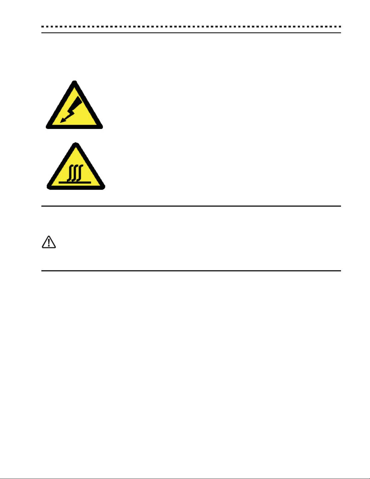
This symbol indicates the electrocution risk.
This symbol indicates the electrocution risk.
When this sign is present, the operator shall move closer to the machine
only when disconnected from power supply.
In this case always wear dielectric gloves.
This symbol indicates the burn hazard.
In case this sign is present, the operator shall get close to the machine
only when all cold parts have warmed to room temperature.
In this case always wear thermal gloves.
5
6CORRECT USE OF THE MACHINE
The machine was designed and manufactured to blend, mix products for the creation of ice cream and slush.
IT IS STRICTLY FORBIDDEN TO USE THE MACHINE FOR OTHER PURPOSES WITHOUT THE PROPER
AUTHORIZATION BY TELME S.P.A., WHICH SHALL NOT BE HELD LIABLE FOR ANY DIRECT OR INDIRECT
DAMAGE THAT MAY RESULT FROM AN IMPROPER USE OF THE MACHINE.
7OPERATOR’S POSITION (WORKSTATION)
The machine requires one operator in charge of loading the ingredients, programming the recipe, starting the processing
and unloading the processed product. The operator shall stand in front of the machine.
Page 6
6
8MACHINE TECHNICAL SPECIFICATIONS
The machine specifications are the following:
English
Vertical batch freezer
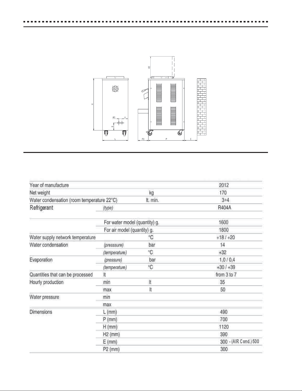
9DATA AND DIMENSIONS OF THE MACHINE
Page 7
English
Operating instructions
9.1 Technical specifications
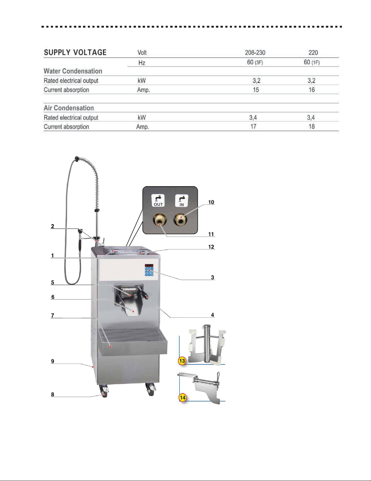
9.2 General description of machine components
7
1 Lid
2 Shower-head for cylinder washing
3 Control push-button panel
4 Extraction door lever
5 Extraction door
6 Chute
7 Shelf
8 Front castors with brakes
9 Rear castors
10 Condensation water inlet
11 Condensation water outlet
12 Cylinder
13 Beater
14 Containing flap used with the beater
Page 8
8
10 SAFETY DEVICES
DO NOT ALTER THE SAFETY DEVICES AND DO NOT UTILIZE THE MACHINE IF THE SAFETY DEVICES
ARE DAMAGED OR MALFUNCTIONING.
THE MANUFACTURER IS NOT RESPONSIBLE FOR POSSIBLE DAMAGES CAUSED TO PEOPLE OR
OBJECTS BY THE ALTERING OR BYPASSING SUCH DEVICES OR RELATIVE CIRCUITS.
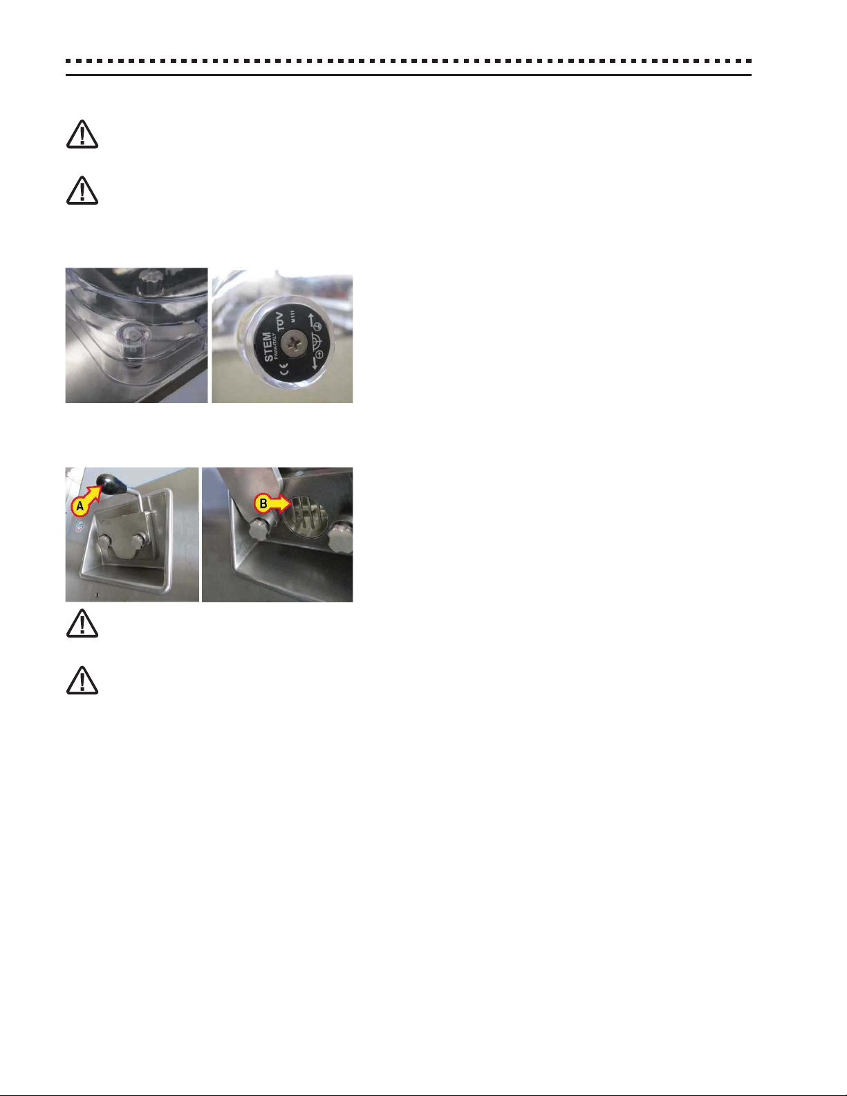
10.1 Safety devices installed on the lids
The machine is equipped with an internal safety magnetic sensor that
detects the magnet installed on the lid. The incorrect installation or the
absence of contact of the lid makes the machine enter into an alarm
state, not enabling its start.
English
Vertical batch freezer
10.2 Safety devices of the extraction door
The machine is equipped with an extraction door that allows sealing
the processing cylinder and opening the door to extract the processed
food items through a lever (A).
The extraction pipe is equipped with a grid fixed (B) that prevents the
insertion of the fingers.
DO NOT FOR ANY REASON INSERT FINGERS OR OBJECTS THROUGH THE GRILL OF THE EXTRACTION
DOOR WHEN THE DEVICE IS IN FUNCTION.
DO NOT HANDLE OR REMOVE THE SAFETY DEVICE AND USE THE MACHINE IF IT IS DAMAGED.
Page 9
English
Operating instructions
11 TECHNICAL DATA
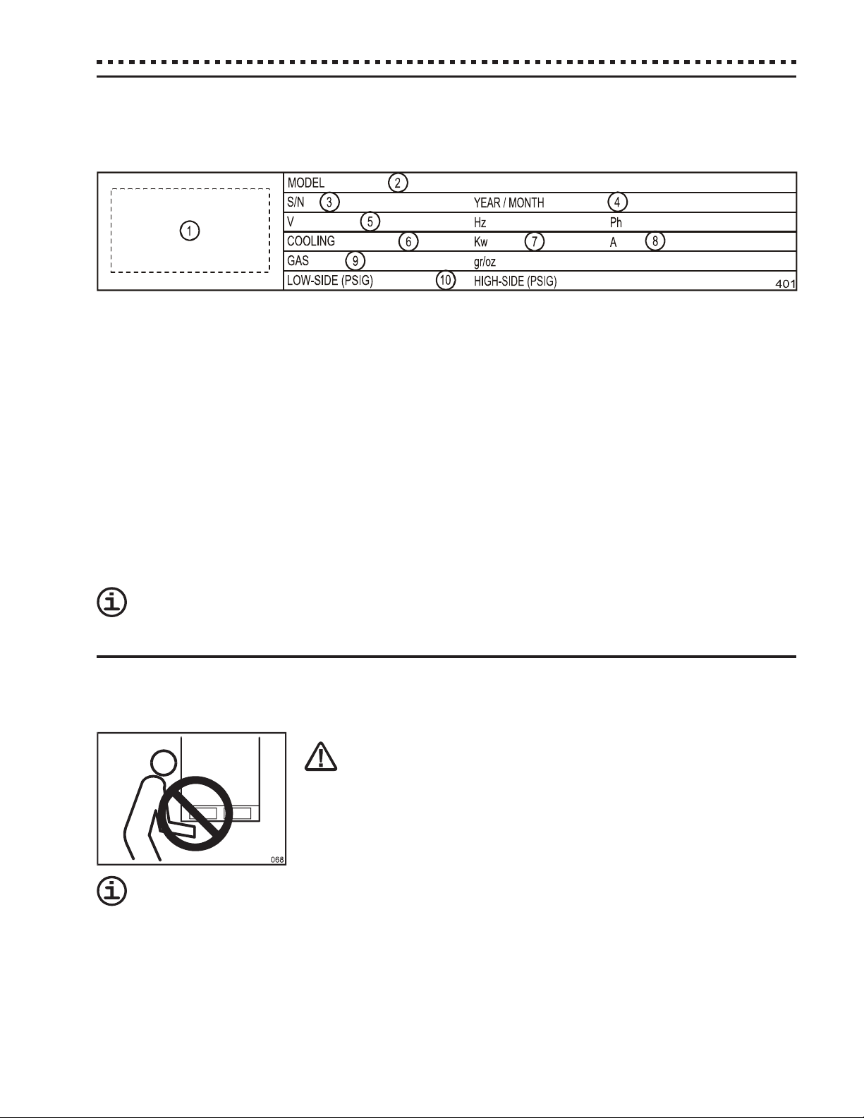
11.1 Technical data plate and CE marking
The technical data plate and CE marking must not be removed. It is placed on the back side of the machine and identifies:
- the name and address of the manufacturer [1];
- the designation of the model [2];
- the relative serial number [3] and the year of construction [4];
- the values of voltage and frequency [5];
- the type of cooling [6], the power [7] and current [8] consumption;
- the type and quantity of refrigerant gas contained [9];
- the values of high and low pressure [10].
9
11.2 Acoustic pressure level
The machine was designed and manufactured in order to reduce the its noisiness at the source.
Measurements performed in the operator’s position on a machine of the same series determined some values.
TEST DOCUMENTS AND CERTIFICATES OF THE TOOLS ARE HELD BY THE COMPANY TELME S.P.A.,
AVAILABLE TO ANY CONTROL AUTHORITY.
12 CARRYING AND UNPACKING
Note: We suggest you to let the Technical Service or qualified technicians carry out the transportation, unpacking
and installation.
TO LIFT THE MACHINE ALWAYS USE AN ADEQUATE LIFTING MACHINE.
ATTEMPTING TO LIFT IT MANUALLY IS DANGEROUS AND CAN DAMAGE YOUR HEALTH.
The machine’s weight specifications, both inclusive of packaging and net, can be
found in both the supplied documents and on the packaging itself.
To prevent the oil contained in the compressor to flow into the refrigerating circuit, it is necessary to
always keep the machine in upright position, both during carrying and during the installation and operation. Always follow the instructions on the packing.
Page 10
10
Vertical batch freezer
English
12.1 Transportation of the packed machine
The packing has been projected to assure at the machine the highest protection.
It is therefore suggested to transport the machine while it is packed as near as possible
at the place where it will be installed.
To carry the packed machine, use an elevator, or a bench trolley, inserting its forks in
the basement’s holes.
12.2 Unpacking
- WOOD PACKING: unnail the top panel, then separate the lateral panels.
- CARDBOARD PACKING; cut the strips and remove the cardboard from the top;
After having opened the packing, make sure the machine isn’t damaged. In case of doubt, do not use it, and call the Seller.
THE OPENING OF THE LATERAL PANEL IS ONLY ALLOWED TO THE TECHNICAL SERVICE OR TO
QUALIFIED TECHNICIANS AND MUST BE MADE BEFORE CONNECTING IT. MAKE SURE NOT TO DAMAGE THE INTERNAL PARTS OF THE MACHINE.
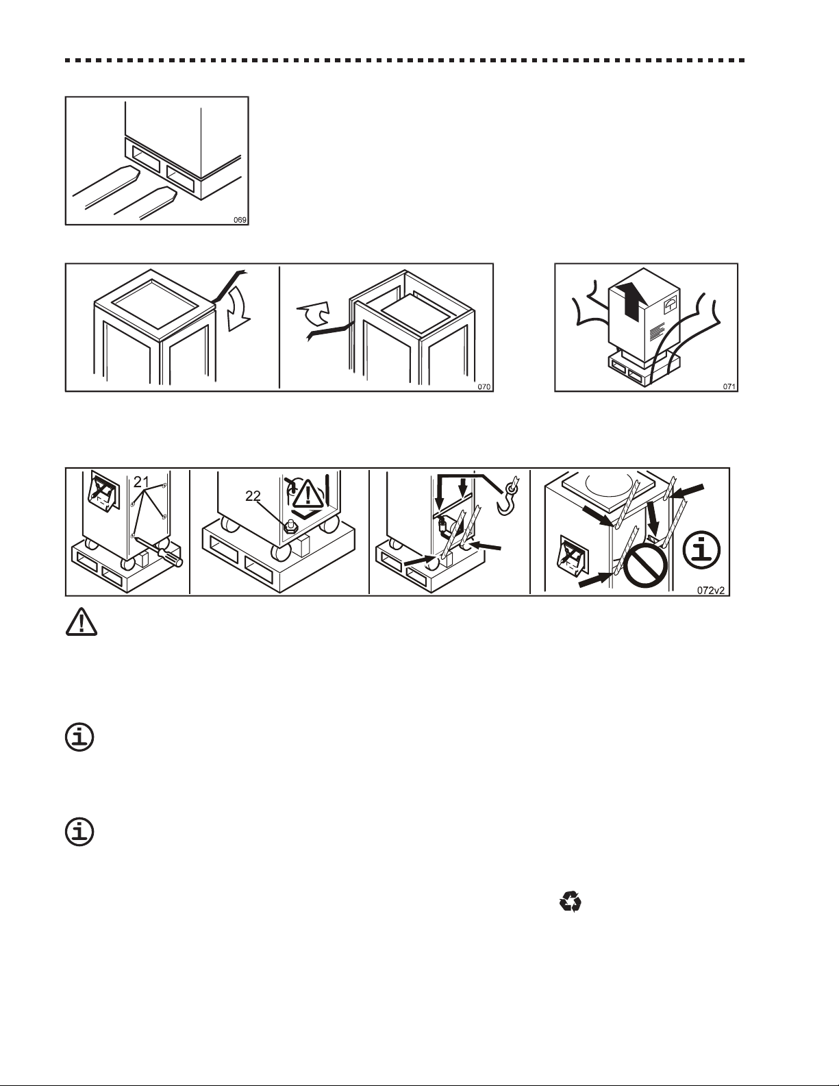
- Remove both the lateral panels unscrewing the relevant fixing screws [21];
- Find and unscrew the bolts [22] which fix the machine’s frame at the packing’s basement;
The outlet of the supply cable is placed on the machine’s lower side. During the lifting make sure not to
damage it.
- Lift the machine from the basement, possibly working on the lower side, near the wheels, and however, only on the
frame’s carrying parts. Remove the basement, and lean the machine on the floor avoiding bumps;
DO NOT insert objects, ropes or brackets for the lifting THROUGH the machine, since these could
damage the inside parts.
- Re-close the lateral panels;
- Replace or move the packing, which is produced with entirely recyclable materials (
).
Page 11

English
Operating instructions
13 INSTALLATION
THE INSTALLATION MUST BE CARRIED OUT ONLY BY THE TECHNICAL SERVICE OR BY TECHNICALLY
AUTHORISED PERSONNEL AND IN COMPLIANCE WITH THE LAWS IN FORCE, ALWAYS FOLLOWING
INSTRUCTIONS OF THE MANUFACTURER.
13.1 Placing and check of the parts
Place the machine on the floor, on a flat and steady surface.
Install the machine away from any source of heat, avoiding a direct exposition to sun
radiation and making sure that air can freely circulate around each side of the machine
itself.
The machines with AIR CONDENSING need at least a 50 cm free space
in front of the condenser’s grill, to assure the refrigerating plant correct
functioning. Further information are reported on the Technical Book
(Technical Data section).
11
Check that the machine is supplied with the lid [5] and that the beater [6] is correctly fixed inside the cylinder with its knob
[7]. The bigger models are supplied with a tilting blade [23] and its fixing knob [24].
Also make sure that in the packing there are the machine’s following parts:
- the extraction door’s chute [9] (in some models the chute is already pre-installed);
- shelf [10], gift pack [11];
- big brush [40], medium brush [41], small brush [42];
- all the technical documentation (in addition to this handbook): the Technical Handbook, the EC’s Conformity Certification and Electrical Test’s Schedule.
13.2 Machine’s parts reassembling
REASSEMBLY MUST BE CARRIED OUT BEFORE CONNECTING MACHINE TO ELECTRIC OUTLET.
- Bring lever [8] in operative position (perpendicular to the extraction door) by loosening and then tightening bolt [39].
Use the 3mm allen key [40] provided.
- if the chute [6] is furnished dismantled, install it below the extraction door [25] fixing it at the frontal panel through the
hand screw [26];
- install the basin support [10] fixing it at the frontal panel through the hand screws [16].
Note: The machine will not operate without the protection flap since the flap includes a safety magnetic contact and
its magnet.
Page 12

12
English
Vertical batch freezer
13.3 Electric connection
THE SUPPLY’S VOLTAGE REQUIRED BY THE DEVICE IS HIGH, SO, IT IS PARTICULARLY DANGEROUS.
THE WORKS ON THE SUPPLY’S ELECTRIC CIRCUITS MUST BE MADE WORKMANLIKE BY QUALIFIED
STAFF.
THE ELECTRIC SAFETY OF THIS AUTOMATIC MACHINE IS REACHED
ONLY WHEN THE SAME IS CORRECTLY CONNECTED, BY QUALIFIED
AND CERTIFIED PERSONNEL, TO AN EFFICIENT EARTHING SYSTEM,
MADE AS PROVIDED FOR IN FORCE SAFETY REGULATIONS.
The manufacturer must not be considered responsible for eventual damages
caused by an inadequate electric or earthing system.
All the electric device's features required for the system’s proportioning are reported
on the Technical Data Plate and on the Technical Handbook.
FOR PREPARING THE ELECTRIC SYSTEM WHICH SUPPLIES THE DEVICE, IT IS COMPULSORY TO
FOLLOW THE PRESCRIPTIVE STANDARDS IN FORCE. IN PARTICULAR:
- The electric capacity of the system must exactly match the supply’s voltage and frequency required by the machine;
- the current capacity of the system must be suitable for the machine’s input;
- the plant must end with a standard socket (3-pole socket for monophasic 1N input and 4-pole socket for triphasic 3F
input) with electrical and mechanical suitable characteristics. The electrical socket’s poles must be marked with
appropriate letters (phase R or phases R-S-T + earth); the earth pole must be properly recognizable;
- the electric socket must prevent, through appropriate mechanical measures, the plug’s wrong connection;
- the electric socket must have, above or annexed, a breaker, conformed to the in force safety laws, with an associated
gearing placed near the machine, in a position easily reachable by the operator. It must also be protected by fuses,
above or annexed, with characteristics suited at the current absorbed by the machine.
A WRONG CONNECTION ON THE EARTH TERMINAL MAY CAUSE SERIOUS DANGER.
A (4 pole plug for triphasic 3F input and 3-pole plug for monophasic 1N input), suitable
with the current socket, must be installed at the end of the machine's power supply
cable.
The machine’s power supply cable is composed by 3 or 4 coloured wires, and eventually
marked with appropriate bands, which must be connected to the relevant plug’s terminals, as shown in the following table.
A WRONG CONNECTION IN THE PLUG’S INSIDE MAY CAUSE SERIOUS DANGER. FOR THE CONNECTION, ONLY ADDRESS YOUR SELVES
TO QUALIFIED AND AUTHORIZED TECHNICIANS.
Kind Wire Wire Code marked near
of supply colour marking band plug’s terminal
EARTH GREEN None PE or
Phase R BLACK R or L1
Phase S RED S or L2
Phase T WHITE T or L3
NEUTRAL BRIGHT or SKY BLUE N
Phase (1N) BROWN — L
Before using the machine it is necessary to:
- connect it to the water network, if the machine features a water condenser (Ref. Par. 13.5);
- carry out the initial functioning checking (Ref. Par. 13.6).
Page 13

English
Operating instructions
13
13.4 Installing permanent wiring
INSTALLATION MUST BE PERFORMED BY A QUALIFIED ELECTRICAL/REFRIGERATION SPECIALIST.
INCORRECT INSTALLATION COULD CAUSE PERSONAL INJURY, SEVERE DAMAGE TO THE MACHINE
AND WILL VOID THE WARRANTY.
THE ELECTRIC SAFETY OF THIS AUTOMATIC MACHINE IS REACHED
ONLY WHEN THE SAME IS CORRECTLY CONNECTED, BY QUALIFIED
AND CERTIFIED PERSONNEL, TO AN EFFICIENT EARTHING SYSTEM,
MADE AS PROVIDED FOR IN FORCE SAFETY REGULATIONS.
The manufacturer must not be considered responsible for eventual damages
caused by an inadequate electric or earthing system.
All the electric machine's features required for the system’s proportioning are reported
on the Technical Data Plate and on the Technical Handbook.
FOR PREPARING THE ELECTRIC SYSTEM WHICH SUPPLIES THE MACHINE, IT IS COMPULSORY TO
FOLLOW THE PRESCRIPTIVE STANDARDS IN FORCE. IN PARTICULAR:
If permanent wiring is required by local codes, the following procedure must be performed:
- The electric capacity of the system must exactly match the supply’s voltage and frequency required by the machine;
- the current capacity of the system must be suitable for the machine’s input;
- bring the wires from the batch freezer to the breaker box (refer to figure 078b);
- the electric breaker must conformed to the in force safety laws, with an associated gearing placed near the machine,
in a position easily reachable by the operator. It must also be protected by fuses, above or annexed, with characteristics
suited at the current absorbed by the machine.
- Install permanent wiring according to local code.
A WRONG CONNECTION ON THE EARTH TERMINAL MAY CAUSE SERIOUS DANGER.
The machine’s power supply cable is composed by 3 or 4 coloured wires, and eventually marked with appropriate bands as
shown in the following table.
A WRONG CONNECTION IN THE PLUG’S INSIDE MAY CAUSE SERIOUS DANGER. FOR THE
CONNECTION, ONLY ADDRESS YOUR SELVES TO QUALIFIED AND AUTHORIZED TECHNICIANS.
Kind Wire Wire Code marked near
of supply colour marking band plug’s terminal
EARTH GREEN None PE or
Phase R BLACK R or L1
Phase S RED S or L2
Phase T WHITE T or L3
NEUTRAL BRIGHT or SKY BLUE N
Phase (1N) BROWN — L
13.5 Connection to the water network
(machines with water condensation)
If your machine features water condensation, it is necessary to prepare tubes for the feeding and draining of the water.
Do not let water from a TOWER in, unless they have been specifically designed to utilize water from a
tower. Unless otherwise specified, the machine is designed to utilize water from a WELL.
Note: the correct water temperature to operate the machine is specified in the Technical Handbook, Par. “Technical
data”.
Page 14

14
English
Vertical batch freezer
The use of below standard tubes and connections may cause water drops, with consequent inconvenience for Your laboratory and, if the drop is abundant with squirts, damage the machine.
Use linen-rubber tubes for water connection, arranged for 15 Bar pressures, interposing a valve or a faucet [B] ABOVE the
delivery pipe; use a 3/4" rubber holder [C], well fixed with a proper band [D] to connect the tubes at the machine’s union.
Note: Tubes for the water feeding of households are on the market (ex. dishwashers) which, in addition to being
cheap, feature the requested characteristics and are predisposed with a rubber holder.
The tubes must be long enough to allow the movement of the machine for cleaning (min. length 1.5 m).
Pipe unions are placed on the machine's rear panel, they are labelled
IN: fresh water INLET
OUT: waste water OUTLET
Follow the following precautions to avoid damages at the machine’s water circuit:
- do not invert the connection of tubes;
- if water in the area presents a high quantity of spur, install a suitable decalcification or filtration machine
above the delivery pipe;
- if not otherwise mentioned in the Technical Handbook, the incoming water’s pressure must be comprehended between 1.5 and 6 Bar (ideal pressure: 3 Bar). If the pressure is higher, it is necessary to interpose a
pressure limiting machine, appropriately regulated, above the delivery pipe.
AVOID CONSTRICTION OR NARROW TURNS OF THE TUBES.
Note: The water outcoming the condensator, though being hot and not drinkable, is not polluted and can be reutilised.
Before storing machine (supplied with water condensation) at temperature lower than 0°C it is ABSOLUTELY necessary to release all water from condenser and from feed and drain pipes, failure to do so will
cause water to freeze and SERIOUSLY DAMAGE refrigerating system. Call Technical Service.
[A] and marked:
13.6 Initial functioning check
At the end of the installation, and before utilising the machine, it is indispensable to let a qualified
technician check the correct connection, by performing the following procedure.
- Before starting, check that the socket's breaker is in the position “0”;
- Insert the plug in the socket, and put the general Breaker in position “1”;
- only the green POWER [Z1] indicator on the control panel must turn on;
- close the cover and press the ON/OFF Pushbutton [K1]. The machine is ready to be used and items on the Display
appear;
Remove the beater from the cylinder before carrying on the check, to avoid letting it function dry.
Page 15

English
Operating instructions
- Open the lid, unscrew the fixing knob [7], pull out the beater [6] from the cylinder, then close the lid.
Note: The machine will not operate when the lid is open or the chute with protection flap is not in place.
- Press the BEATING Pushbutton [K4] and check that beater’s shaft turns CLOCKWISE (as shown in the picture). In
this case, the machine is correctly connected and ready to be used;
Note: do not unnecessarily start the refrigerator.
- If the rotation is COUNTERCLOCKWISE, the connection to the three-phase electrical supply is wrong, and
must be changed proceeding as follows:
- Turn off the machine by pressing the ON/OFF Pushbutton [K1];
TURN THE SOCKET'S BREAKER TO THE “0” POSITION, THEN UNPLUG MACHINE;
15
- Open the plug’s shell and invert TWO of the THREE conductors connected at the
phases (R-S, R-T or S-T);
- Close the plug’s shell, plug in the machine and repeat the check.
14 MACHINE’S OPERATION
14.1 Warnings
WHEN USING THE MACHINE, AS WITH ALL ELECTRICAL APPARATUS, ESSENTIAL RULES MUST BE
COMPLIED WITH, PARTICULARLY:
- never touch it if your feet or hands are wet;
- never operate it while barefoot;
- never pull the supply cable to disconnect it from the mains network;
- avoid liquids to penetrate in the machine, for example during its cleaning;
- forbid children and unable people to operate it.
In case of failure and/or malfunctioning of the machine - and every time you notice damages, mainly at the supply cable or
at the safety machines - turn off the power supply. Contact qualified and certified personnel for assistance.
EDIBLE FATS ARE GROUND FOR BACTERIA PROLIFERATION. WE RECOMMEND TO WASH AND CLEAN
WITH THE MAXIMUM CARE EVERY PART IN CONTACT WITH PRODUCT, WHEN THE USE OF THE
MACHINE IS SUSPENDED.
NEVER operate the machine in DRY conditions or with an amount of mixture other than the one recommended.
NOT RESPECTING THESE RULES, IN ADDITION TO VOIDING ANY FORM OF WARRANTY, CAN SERIOUSLY COMPROMISE THE SAFETY, PERFORMANCES AND FUNCTIONING OF THE SAME MACHINE.
The machine is designed to operate two separate main Cycles: the TEMPERATURE CYCLE and the TIME CYCLE:
- with Temperature Cycle the machine cools the mixture down to Final Temperature [Tf] which is set to the desired final
thickness;
Page 16

16
English
Vertical batch freezer
- with Time Cycle the machine cools the mixture down according to Freezing Time [M] which is set according to the
product’s quantity and type.
Before starting production, we recommend to carefully read Par. 14.2 - “Controls and Indicators” and Par. 14.3 - “Setting
Up” of this manual.
14.2 Controls and indicators
All controls and indicators for the use of the machine are grouped in a single control
panel placed on the front panel. Its functioning is low-voltage electronically managed.
I In this manual, the buttons and indicators are identified with the relative symbol, and/or
with an imprint ([K…] for pushbuttons, [Z…] for indicators).
The functioning of every command is described hereby: to obtain the best results, an
acknowledgment is suggested.
ON/OFF Pushbutton [K1] - POWER Indicator [Z1]
When the electric supply is connected, the machine is ready to be turned on, the green indicator light [Z1] is on. By
pressing the button, the machine turns on and the other buttons are enabled.
BEATING Pushbutton [K4] - BEATING Indicator [Z4]
By pressing the pushbutton, the beater only will start rotating (clockwise). To stop, press pushbutton again.
When the pushbutton’s indicator [Z4] is on the beater is rotating (clockwise).
Note: When the production cycle is stopped by pressing EXTRACTION Pushbutton [K9], press BEATING Pushbutton
to continue cycle from where it stopped.
TEMPERATURE CYCLE Pushbutton [K5] - TEMPERATURE CYCLE Indicator [Z5]
By pressing the pushbutton, the TEMPERATURE CYCLE is activated, together with BEATING: the cylinder’s content is
refrigerated at Final Temperature [Tf] as follows:
- when indicator [Z5] is on, Temperature Cycle is in operation:
- REFRIGERATION indicator [Z7] is also on to indicate that refrigerating system is in operation.
- on completion of the cycle the product is stirred inside the cylinder: the indicator [Z5] is on to show the cycle is still
operative;
- press pushbutton to end the cycle and stop the machine or to manually stop the cycle.
TIME CYCLE pushbutton [K7] - REFRIGERATION Indicator [Z7]
By pressing the pushbutton, the TIME CYCLE is activated, together with BEATING: the cylinder’s content is refrigerated for
the set Freezing Time [M] as follows:
- when indicator [Z7] is on, refrigerating system is in operation;
- the cycle automatically stops on completion of the FreezingTime and the refrigerator turns off. The beater continues to
work to prevent the formation of ice inside the cylinder (BEATING indicator [Z4] remains on). Press BEATING Pushbutton
[K4] to stop beater.
- by pressing TEMPERATURE CYCLE again, the total set Freezing Time is resumed.
Page 17

English
17
Operating instructions
EXTRACTION Pushbutton [K9] - EXTRACTION Indicator [Z9]
By pressing the pushbutton the beater starts rotating quickly COUNTERCLOCKWISE in order to let the finished ice-cream
out of the extraction door, at the same time its indicator [Z9] turns on.
DO NOT USE this control button when product inside the cylinder is in LIQUID form. Failing to do so
would cause the product to splash from inside the cylinder.
The beater’s quick counterclockwise rotation can also be used to fold in any ingredients (i.e. chocolate) added towards the
end of the cycle. Proceed as follow:
- add ingredients through lid’s grill without stopping machine;
- press EXTRACTION [K9], and let beater rotate counterclockwise untill all the product is extracted;
- press BEATING [K4] to resume cycle from the point where it stopped.
BUZZER Pushbutton [K6] - BUZZER Indicator [Z6]
The machine features a buzzer to inform when cycle is completed. To enable it, press this button (the [Z6] indicator lights
up).
SET UP Pushbutton [K8]
By pressing the pushbutton, the Display shows the operative cycles’ main values. Should the need arise to modify them,
press ADJUSTMENT [K2] and [K3]. For more details see Par. 14.3 - “Setting Up”.
ADJUSTMENT Pushbuttons [K2] - [K3]
These pushbuttons are enabled only after pressing SET UP [K8]. They increase or decrease set values. For more details
on their use, see Par. 14.3 - “Setting Up”.
Digital display
A) when the machine is not operating, the Display shows the previous cycle’s read-
ings;
B) DURING and AT THE END of a TEMPERATURE Cycle, the Display shows the
product’s temperature;
C) DURING a TIME Cycle, the Display shows any Freezing Time left, which is preceded
by an animated square symbol;
D) AT THE END of a TIME Cycle, the Display shows the entire Freezing Time, which
is preceded by a fixed “t”;
E) when TIME CYCLE stops (timer is on pause) the Display shows any Freezing
Time left, which is preceded by a flashing “t”;
F) when Display shows “ooo” (three small squares), the machine is not working due
to an operational irregularity:
• the lid is not correctly closed;
• the chute with protection flap is not correctly installed;
• a protection machine has come into operation. See Section 10 - Malfunctions.
Page 18

18
Vertical batch freezer
English
14.3 Setting Up
The machine has been adjusted during testing with optimal settings. Do not modify settings unless
strictly necessary.
Note: Set up the machine when not in function, before starting production.
- Press ON/OFF [K1], the machine is now on. Press SET UP [K8]. On the display “P1” will flash, showing that you are
now in SET UP mode and can proceed to set up the required temperature for the TEMPERATURE Cycle;
Note: If you wait longer than 7…8 seconds without pressing any pushbutton, any new setting will be automatically
stored and the SET UP mode will terminate.
- press SET UP [K8] again. The display shows the Final Temperature [Tf]. If required, adjust temperature by pressing
ADJUSTMENT [K2] or [K3]. The manufacturer’s preset temperature is –7°C (20 °F) (suitable to ice-cream production). The adjustment range is –12°C…+6°C ( 5°F... 50 °F);
The Final Temperature [Tf] needs programming in accordance to the antifreezing ingredients (i.e. sugar,
alcohol) contained in the mixture. As a guideline, mixtures with LOW content of antifreezing ingredients
can reach –5…–6°C (23... 21°F), mixtures with MEDIUM content of antifreezing ingredients can reach
– 7… – 8°C (20... 18 °F), mixtures with HIGH content of antifreezing ingredients can reach –9…–10°C
(17...14°F).
- press SET UP [K8] again. On the display “P2” will flash, showing that you can proceed to set up the required time for
the TIME Cycle.
- press SET UP [K8] again. The Display shows Freezing Time [M] (in minutes). If needed, adjust it by pressing ADJUSTMENT [K2] or [K3]. The manufacturer’s setting is 8'. The adjustment range is 1'…60';
- on again pressing the SET UP [K8], the figure “P3” will appear flashing on the display. On pressing the PROGRAMMING
button [K8] yet another time, apparatus operating time for the production of gelato will appear (thousands "H-0",
hundreds, tens, units "000" expressed in hours).
- when you press SET UP [K8] again (or wait for a few seconds), the Display briefly shows [- - -], indicating that set up
data have been stored, the SET UP mode terminates and the machine is ready to be used.
14.4 Setting up for production
In machines with water condensation, check that the condensation water’s faucet is open;
- check that POWER indicator [Z1] is on. If not, check that machine is plugged in and Main Breaker is turned on
(on “1”);
- Check the lid is closed and the chute with protection flap is in position, otherwise the machine will not
operate. NO “ooo” (three small squares) should show on the Display;
- press the ON/OFF Pushbutton [K1].
Do not start beater before pouring mixture into the cylinder. The beater must not function dry, otherwise
it will be damaged.
Page 19

English
Operating instructions
19
- before beginning the production, wash, rinse and proceed at the sanitation with a
detergent and disinfecting solution (see Section 13-14 PRE WASHING and
WASHING).
Note: If you plan to have more than one consecutive production cycles, you can
avoid the washing between a cycle and the other, making sure you begin
with the clearer mixtures.
Before starting production ALWAYS check that beater’s fixing knob [7]
and the tilting blade’s fixing knob [24] (when supplied) are FIRMLY TIGHTENED and that all the relevant gaskets are intact and clear of any fat. If
the knobs should accidentally unscrew and fall in the cylinder during
the functioning, they would cause serious damages at the machine.
- check that extraction door is firmly closed and pour mixture in the cylinder. Only
use suitable perfectly preserved ingredients, in the correct amount. The maximum
and minimum amounts are indicated in the Technical Handbook, in the “Technical
Data” section.
Unsuitable mixture or insufficient amount of it can cause the development of ice, and cause damages or irregular functioning at the cylinder
and beater, while an excessive amount of mixture can forbid the correct freezing, in addition to causing an excessive stress at the motor
and beater and overflows of product.
14.5 TEMPERATURE Cycle production
During TEMPERATURE CYCLE the machine stirs and refrigerates mixture at the set Final Temperature [Tf] until the
required thickness is reached. Stop cycle by pressing the cycle’s pushbutton.
- Close cylinder’s lid;
The Final Temperature [Tf] needs programming in accordance to the antifreezing ingredients (i.e. sugar,
alcohol) contained in the mixture. As a guideline, mixtures with LOW content of antifreezing ingredients
can reach –5…–6°C (23 ... 21°F), mixtures with MEDIUM content of antifreezing ingredients can reach –
7…–8°C (20...18 °F), mixtures with HIGH content of antifreezing ingredients can reach –9…–10°C (17...14
°F).
- check and adjust, if required, the previously set Final Temperature (ref. 14.3 - Setting Up). The manufacturer’s setting
(–7°C) (20 °F), is suitable for the majority of ice-cream mixtures;
- press the BUZZER Pushbutton [K6] to enable the buzzer at the end of the freezing cycle (the relative indicator [Z6]
lightens);
- press TEMPERATURE CYCLE Pushbutton [K5];
- wait for the end of the processing, that is when the programmed Final Temperature [Tf] is reached, when the REFRIGERATING SYSTEM indicator [K7] turns off and when you hear a sound signal.
- press TEMPERATURE CYCLE Pushbutton [K5] to end cycle and stop machine.
Note: At the end of the cycle, it is recommended to immediately remove product to avoid curdling due to prolonged
beating.
Page 20

20
Vertical batch freezer
English
14.6 TIME Cycle production
During TIME CYCLE, the machine stirs and refrigerates mixture for the set Freezing Time [M]. Refrigeration automatically
stops at the end of the set time.
- close the cylinder’s lid;
- check and adjust, if required, the previously set Freezing time [M] (ref. 14.3 - Setting Up). The manufacturer’s setting
(8 min.) is suitable for the majority of ice-cream mixtures;
- press the BUZZER Pushbutton [K6] to enable the buzzer at the end of the freezing cycle (the relative indicator [Z6]
lightens);
- press TIME CYCLE Pushbutton [K7];
- wait for the end of the processing, that is when the REFRIGERATING SYSTEM indicator [Z7] turns off, when the letter
“t” appears on the display and when you hear a sound signal.
- press BEATING Pushbutton [K4] to stop machine.
14.7 Extracting the product
- Position an idoneous basin on the shelf;
- FIRSTLY fully open the extraction door and THEN press EXTRACTION Pushbutton [K9]. Transfer mixture into the basin
using the scoop provided.
- stop the beater by pressing the EXTRACTION Pushbutton [K9];
- open the lid and detach the product eventually left on the beater’s blades (by using the scoop provided letting it settle on
the bottom of the cylinder.
- press the EXTRACTION Pushbutton [K9] to extract the left over product;
- stop the beater by pressing the EXTRACTION Pushbutton [K9] and close the extraction door.
Carry out an accurate cleaning:
- pre-washing (par. 15) if you soon proceed with another production;
- washing (par.16) if the production has come to an end.
15 PRE-WASHING
Do not carry out the rinsing having a very cold cylinder.
- Proceed with rinsing to eliminate the residual ice-cream, using 3,5 gal. of warm water (30°C), if you soon will produce
other ice-cream;
- Proceed with rinsing to eliminate the residual ice-cream, using 3,5 gal. of warm water (30°C) and, if the production has
come to an end, proceed with simple washing, accurate washing and disassembling of the parts (see 16 WASHING).
Page 21

English
Operating instructions
16 WASHING
THE FATS CONTAINED IN THE ICE-CREAM MIXTURES ARE IDEAL FOR THE GROWTH OF BACTERIA.
WE RECOMMEND TO WASH AND SANITIZE WITH THE MAXIMUM CARE EVERY PART IN CONTACT WITH
PRODUCT, IN ACCORDANCE WITH CURRENT HEALTH REGULATIONS.
For a long life of the machine we suggest not to use solvents, abrasive detergents, or rough sponges, in
particular on the plastic and rubber parts. During the washing operations and in particular during the
rinsing, activate the beating only for the suggested periods. Otherwise you could damage the machine.
DO NOT press the REFRIGERATION Pushbutton [K5] during the washing. Otherwise you would freeze
the water and break the parts of the machine. Do not press the EXTRACTION Pushbutton [K7] because
all the washing solution would come out from the top of the machine. Do not carry out the washing
having a very cold cylinder.
1 Simple washing
STEP 1
Prepare a pail with a solution composed by hot water
(50°C)(122°F) and detergent GOLDEN GLO by SPARTAN
CHEMICAL, respecting the following amount:
use 3,5 gallons of hot water and 1,3/4 oz. of detergent;
STEP 2
Check that the extraction door is closed, open lid, pour
the detergent solution in the tank and close the lid again.
STEP 3
Press the beating pushbutton [K4], this will cause the
detergent solution to be agitated in the tank.
STEP 4
2 minutes later, press the beating pushbutton [K4]
again to stop the agitation,place a pail beneath the
extraction door and clear out the tank.
STEP 5
Rinse only with hot potable water (50°C) (122°F), repeating
steps 2,3,4 until the rinse water being drawn from the tank
is clear.
21
2 Accurate washing and disassembling of the parts
CARRY OUT THESE OPERATIONS ONLY
WITH THE SOCKET'S MAIN BREAKER ON
POSITION “0”. THE [Z1] INDICATOR OF THE
IGNITION BUTTON ON THE CONTROL PANEL
MUST BE TURNED OFF.
Page 22

22
STEP 1
- extract the rod [25] from the lid’s hinge and remove the lid [5];
- unscrew counterclockwise the fixing knob [7], extract the support
[22], the safety peg [21] and remove the movable blade [20] from
support [22];
RESIDUAL HAZARD: BEATER'S BLADES AND
SCRAPERS ARE SHARP ALONG BOTTOM AND
EXTERNAL SIDE EDGES. IT IS RECOMMENDED TO USE
SUITABLE PROTECTIVE GLOVES AND TO HANDLE THE
BEATER ONLY BY HOLDING THE CENTRAL HUB AND
NOT THE BLADES.
- unscrew counterclockwise the fixing knob [7] and extract the beater
[6];
- remove from the beater [6], fixed centering runners [50], side
scrapers [51] and the bottom scraper [52];
- unscrew counterclockwise the knob [26] and remove the protection
flap chute [9];
- remove the shelf [10] by unscrewing the hand screws [16];
- unscrew counterclockwise the fixing knobs [41] and extract the
extraction door [40], using a provided allen key [54], unscrew the
tightening bolt [53] and remove the lever [55].
English
Vertical batch freezer
TAKE CARE NOT TO ALLOW WATER OR ANY LIQUID
INSIDE THE MACHINE.
STEP 2
Prepare a pail with a solution composed by 1 gal. of room temperature water and 1/2 oz.of disinfecting SANI-T-10
manufactured by SPARTAN CHEMICAL and carry out the
cleaning of the underlisted parts, using the provided brushes as
illustrated in the drawings.
- the beater [6] and the fixing knob [7];
- the upper blades [50],the side scrapers [51] and the bottom scraper [52];
- the lid [5];
- the locking door [40]
- the extraction door chute and protection flap [9];
- the drip tray support [10];
- the movable blade support [22], the safety peg [21], the
fixing knob [7] and the movable blade [20].
Page 23

English
Operating instructions
STEP 3
Prepare a pail with a solution composed by 3 gal. of water and
1, 1/2 oz. of disinfecting SANI-T-10 manufactured by SPARTAN
CHEMICAL and immerse for at least 5 minutes the underlisted
parts:
- the fixing knobs [7];
- the locking door [40];
- the extraction door chute and protection flap [9];
- the beater [6];
- the upper blades [50];
- the side scrapers [51];
- the bottom scraper [52];
- the movable blade support [22];
- the movable blade [20].
- the safety peg [21];
23
STEP 4
Before reassembling the components, accurately wash the fixed
parts of the machine as illustrated in the drawings and underlisted,
using the solution previously prepared (see STEP 2).
- the extraction pipe, the safety grill, the groove and its edges
using the provided brush
- the upper surface, the lid's rod and the inside of the tank;
STEP 5
A potable water rinse is not necessary unless so specified by
state or local ordinance.
Page 24

24
3 Reassembly
THESE OPERATIONS MUST BE CARRIED OUT ONLY WITH THE SOCKET'S MAIN BREAKER ON "0"
STEP 1
After carrying out the washing as previously described, reinstall
the machine's parts as follows:
- Assemble the upper blades [50], the side scrapers [51]
and the bottom scraper [52] on beater's supports [6].
Carefully place the beater into the cylinder, taking
care to keep it vertical without dropping it.
- The slot on the beater's hub [27] goes into the shaft
clutch [28];
Before tightening knob [7], always check that the
gasket [G] is in perfect conditions and in place,
an that is clear of any fat as to prevent knob from
accidentally coming lost. If the knob should fall
into the cylinder during production cycle, it would
cause serious damage to the machine.
English
Vertical batch freezer
Note: Gaskets must be periodically replaced.
- Firmly tighten beater's fixing knob [7];
- assembly the movable blade [20] with support [22], insert
the safety peg [21] respecting the correct position and fix
the support [22] to the pin [56] placed on the surface of the
machine;
- put lid [5] in place, insert pin [25];
- fix the lever [55] to the locking door [40] unscrewing the
tightening bolt [53] with a provided allen key [54]; install the
locking door [40] as illustrated in the drawing, taking care
not to damage it , not to touch its internal surface [X] in
contact with the extraction pipe [45]; reinstall the flat
springdriver [46] with the relative big spring [47] and the
fixing knob [41] on the left side, the conic springdriver [48]
with the relative small spring [49] and the fixing knob [41]
on the right side;
- install the chute and protection flap [9] beneath the
extraction door [25], fixing it to the hinges [26];
- install the shelf [10] fixing it to the front panel through the
knobs [16].
Page 25

English
Operating instructions
25
4 Sanitization
After reinstalling all the machine’s components (as previously described), carry out a sanitization with water solution and
disinfecting SANI-T-10 manufactured by SPARTAN CHEMICAL. Follow accurately the next steps:
STEP 1
Prepare a pail with a solution composed by room temperature water
and disinfecting SANI-T-10, respecting the following dosings:
use 3,5 gallons of water and 1, 3/4 oz. of disinfecting SANI-T-10;
STEP 2
Check that the extraction door is closed, open lid, pour the detergent
solution in the tank and close the lid again.
STEP 3
Press the beating pushbutton [K4], this will cause the sanitizing
solution to be agitated in the tank.
STEP 4
5 minutes later, press the beating pushbutton [K4] again, place a
pail beneath the extraction door and clear out the tank.
STEP 5
A potable water rinse is not necessary unless so specified by state
or local ordinance.
After the sanitization, close the lid and do not touch
with the hands anymore, nor dry with clothes or paper
all parts in direct contact with food.
Note: Additionally to the operations mentioned in this Chapter,
it is recommended to clean machine’s outer panels and
all of its outside parts.
17 MAINTENANCE
The machine requires a very limited maintenance. Periodically, we suggest to:
- check the good state of the parts of the machine. The disassembly, for example during the accurate washing, is an
ideal opportunity for a similar check (ref. Par. 17.1);
- check that electric power cable, pipe fittings (rubber holder) and water pipes (where present) are not damaged;
It is then useful to maintain the external panels clean and the surrounding area. Dust, paper fragments or other small objects
may penetrate in the machine through the ventilation loopholes (in particular if equipped with air condensation and rapidly
compromise its correct functioning.
The inside parts, to which the user MUST NOT accede, must be checked by the Technical Service.
Page 26

26
Vertical batch freezer
English
17.1 Maintenance during the components disassembling
Check the integrity of gaskets (indicated with [G] in the figure) and substitute those that
are deteriorated.
G
G
- remove the old gaskets by using a sharp non-tool, possibly non-metallic, paying attention not to scratch the seating of
the gaskets themselves;
- clean the seatings and the gaskets from any kind of grease before inserting the new gaskets.
Use exclusively original, compatible with food, rubber gaskets. The spare bag
contains a complete series of gaskets approved by the manufacturer.
093
Check that the plastic runners' scraping edges are not scratched or dented, and that
the side runners are not worn as shown in the picture. If they appear worn, replace
them.
To correctly replace the gaskets it is necessary to:
A thorough scraping of the cylinder will provide BEST PERFORMANCE
by the batch freezer and HIGH QUALITY ICE-CREAM. Therefore we
recommend to frequently replace plastic scrapers (at least once every
THREE MONTHS).
A yearly preventive replacement of all wearing parts and all gaskets is recommended. We suggest you to always keep a
spare supply: to order it, refer to the Spares Section contained in the Technical Handbook.
17.2 Yearly maintenance
Periodically (basing yourself on the environmental conditions in which the machine operates) and in any case once every
year, make sure to have a general checkup.
THE CHECK-UP MUST BE MADE BY THE AUTHORISED TECHNICAL SERVICE, OR, IN ANY CASE, BY
TECHNICALLY AUTHORISED PERSONNEL WITH ADEQUATE TOOLS. THE MAINTENANCE OPERATIONS
RESERVED TO THE SERVICE TECHNICAL CAN BE DANGEROUS IF CARRIED OUT BY NON-PROFESSIONALS, THEREFORE, FOR HIS OWN SAFETY, THE USER MUST NEVER CARRY THEM OUT.
18 PERIODS OF INACTIVITY
If long periods of inactivity are foreseen, proceed as follows:
- wash up completely the machine (see Section 16-17);
- switch off the power breaker and unplug the machine;
- machines with WATER condensation: close the water faucet and relieve pressure from inside the delivery pipe by
unscrewing one of the pipe fittings. Remove both delivery and drain pipes and let all water out. Before using the pipes
again, following a long period of inactivity, check for any damages or cracks and replace, if necessary, pipe fittings’
gaskets.
- if the machine will be stored in a different place, group all the documentation, together with the present manual, and
enclose it at the machine (i.e. in the cylinder).
Before storing machine (supplied with water condensation) at temperature lower than 0°C it is ABSOLUTELY necessary to release all water from condenser and from feed and drain pipes, failure to do so will
cause water to freeze and SERIOUSLY DAMAGE refrigerating system. Call Technical Service.
Page 27

English
Operating instructions
27
19 MALFUNCTIONS
WE RECOMMEND YOU TO CALL IMMEDIATELY THE TECHNICAL SERVICE IF A MALFUNCTION DIFFERENT FROM THOSE HERE DESCRIBED IS FOUND.
Note: the following malfunctions do not refer to problems noticed in the installation phase, but ONLY on correctly
installed - and already functioning - machines.
THE MACHINE DOES NOT WORK OR STOPS WORKING.
With the Main Breaker on 1 the POWER indicator [Z1] DOES NOT TURN ON.
Cause: The plug is not correctly plugged.
The plug is defective. A qualified technician should substitute it.
Power in the socket is missing. Check that the breakers, the omnipolar switches and the
differentials (lifesavers) on the electric plant are closed. If they aren’t, before closing them,
make sure that no one is making electrical maintenance.
A protective fuse of the electric plant is blown. Find and eliminate the eventual cause of
overload. Substitute blown fuses with others of the same kind.
The supply cable is defective. BEFORE, cut down electrical feeding at the socket by opening
the breaker above it, then disconnect the plug and call the Technical Service.
DO NOT TOUCH THE DAMAGED ELECTRICAL CABLES BEFORE HAVING CUT DOWN
THE ELECTRICAL SUPPLY!
With the Main Breaker on 1 the POWER indicator [Z1] TURNS ON, but the display shows 3 small squares
and the machine does not work.
Cause: The lid is not correctly closed or tends to open;
The product lifts the lid due to an excessive quantity or an excessive volume increase. Use a
smaller amount of mixture or more suitable ingredients.
The lid’s magnet is damaged. Call the Technical Service.
THE MAGNETS AND THEIR CONTACTS ARE IMPORTANT SAFETY MACHINES!
Cause: The refrigerator’s safety pressure switch comes on. Check the machine’s air/condensing
water supply. See also par. Malfunctions: “The refrigeration is insufficient…”
The compressor’s back up relay switches off, following excessive stress (repeated starts,
high pressure, overheating). Stop the machine, wait a few minutes and try again. If the fault
should not be eliminated, or should frequently repeat, call the technical service.
Note: it may be necessary to wait up to 30 minutes for the thermal protections to cool down.
Cause: The Beater’s back up relay switches off, following overuse or mechanical overload. Check
that the eventual product in the cylinder is not excessively dense and that there are no other
causes of mechanical stress.
Overloading of the beater motor during TEMPERATURE CYCLE can be caused by the product excessive thickness. This is because the Final Temperature is too low for the type of
mixture in use. Set Final Temperature to a higher setting (less cold).
Stop the machine, wait a few minutes and try again. If the fault should not be eliminated, or
should frequently repeat, call the technical service.
Note: it may be necessary to wait up to 30 minutes for the thermal protections to cool down.
Page 28

28
English
Vertical batch freezer
With the Main Breaker on 1 the POWER indicator [Z1] TURNS ON, but the machine does not work.
Cause: Break down of inside parts or at the electronic controls. Call the Technical Service.
THE TEMPERATURE CYCLE DOESN'T AUTOMATICALLY END BECAUSE PRODUCT DOES
NOT REACH PRESET FINAL TEMPERATURE.
Cause: Final Temperature [Tf] is too low. Final Temperature [Tf] needs programming in accordance to
the antifreezing ingredients (i.e. sugar, alcohol) contained in the mixture. As a guideline,
mixtures with LOW content of antifreezing ingredients can reach –5…–6°C, mixtures with
MEDIUM content of antifreezing ingredients can reach –7…–8°C, mixtures with HIGH content of antifreezing ingredients can reach –9…–10°C.
THE MACHINE CAUSES REPEATED RELEASES OF THE MAINS ELECTRICAL PROTECTIONS OR THE INTERRUPTION OF MAINS FUSES.
Cause: The capacity of the electrical plant is not sufficient to feed the machine.
The electrical characteristics of protections and fuses are not adequate.
Inside breakdown of the machine. Call the technical service.
THE REFRIGERATION IS INSUFFICIENT OR DISACTIVATES IN AN ANOMALOUS WAY.
AIR CONDENSATION machines
Cause: Obstacles are placed at the air conditioning’s opening, at a distance lower than that de-
scribed. Restore the minimal distance reported in the Technical Handbook.
The room temperature is too high and condensation is inadequate.
The air condensator is dirty. Request the cleaning at the Technical Service.
The condensator’s fan is broken. Call the Technical Service.
Break down of the refrigerating circuit or at the electrical controls. Call the Technical Service.
WATER CONDENSATION machines:
Cause: The flow of condensation water is interrupted or insufficient.
The water tubes present constrictions. Avoid constrictions.
The water condensation faucet/s are partially or totally closed.
The static pressure valve must be newly regulated, otherwise it is broken. Call the Technical
Service.
Note: To check if the water correctly flows and if the static pressure valve is regulated, it is sufficient
to temporarily detach the water outlet tube (at the end not connected at the machine). Water
must flow only when the refrigerating plant is in function.
The incoming water’s temperature is higher than that prescribed in the Technical Handbook.
Cause: The compressor is overheated due to a lack of ventilation. Clean the scots and restore the
minimal distances for the circulation of air at the sides of the machine.
Note: it may be necessary to wait up to 30 minutes for the thermal protections to cool down.
Break down at the refrigerating circuit, or at the electrical controls. Call the Technical Service.
Page 29

English
Operating instructions
UNUSUAL NOISINESS.
The noisiness comes, mainly, from the cylinder, when the beating is activated.
29
Cause: A layer of ice has developed between the beater and the cylinder: the mixture is not idoneous,
or is not sufficient.
The Beater’s scrapers might be damaged or too worn. Check that the scrapers edges are not
scratched or dented, and that the side scrapers are not worn as shown in the picture. If they
appear worn, replace them.
The beater and/or the cylinder are damaged or excessively worn. Call the Technical Service.
Cause: The tilting blade’s fixing knob (where featured) is loosened. Check the state of the gasket(s)
(eventually substitute them) and tighten again the fixing knob(s).
The beater and/or the cylinder have gone through a sudden temperature change, and stress
mechanically. Stop the machine and wait a few minutes.
The noisiness DOES NOT come from the cylinder, or is also present when the beating is not activated.
Cause: Inside break down. Call the Technical Service.
Page 30

30
English
Vertical batch freezer
Page 31

WARRANTY
CUSTARD EQUIPMENT AND BATCH EQUIPMENT
1. Scope:
PW Stoelting, L.L.C. (“Stoelting”) warrants to the first user (the “Buyer”) that the freezing cylinders,
hoppers, compressors, drive motors, speed reducers, beaters, and auger shafts of Stoelting custard
equipment and batch equipment will be free from defects in materials and workmanship under normal
use and proper maintenance appearing within two (2) years, and that all other components of such
equipment manufactured by Stoelting will be free from defects in material and workmanship under
normal use and proper maintenance appearing within twelve (12) months after the date that such
equipment is originally installed.
2. Disclaimer of Other Warranties:
THIS WARRANTY IS EXCLUSIVE; AND STOELTING HEREBY DISCLAIMS ANY
IMPLIED WARRANTY OF MERCHANTABILITY OR FITNESS FOR PARTICULAR
PURPOSE.
3. Remedies:
Stoelting’s sole obligations, and Buyer’s sole remedies, for any breach of this warranty shall be the
repair or (at Stoelting’s option) replacement of the affected component at Stoelting’s plant in Kiel,
Wisconsin, or (again, at Stoelting’s option) refund of the purchase price of the affected equipment,
and, during the first twelve (12) months of the warranty period, deinstallation/reinstallation of the
affected component from/into the equipment. Those obligations/remedies are subject to the
conditions that Buyer (a) signs and returns to Stoelting, upon installation, the Start-Up and Training
Checklist for the affected equipment, (b) gives Stoelting prompt written notice of any claimed breach
of warranty within the applicable warranty period, and (c) delivers the affected equipment to Stoelting
or its designated service location, in its original packaging/crating, also within that period. Buyer shall
bear the cost and risk of shipping to and from Stoelting’s plant or designated service location.
4. Exclusions and Limitations:
This warranty does not extend to parts, sometimes called “wear parts”, which are generally expected
to deteriorate and to require replacement as equipment is used, including as examples but not
intended to be limited to o-rings, auger seals, auger support bushings, and drive belts. All such parts
are sold
AS IS.
Further, Stoelting shall not be responsible to provide any remedy under this warranty with respect to
any component that fails by reason of negligence, abnormal use, misuse or abuse, use with parts or
equipment not manufactured or supplied by Stoelting, or damage in transit.
THE REMEDIES SET FORTH IN THIS WARRANTY SHALL BE THE SOLE LIABILITY
STOELTING AND THE EXCLUSIVE REMEDY OF BUYER WITH RESPECT TO
EQUIPMENT SUPPLIED BY STOELTING; AND IN NO EVENT SHALL STOELTING
BE LIABLE FOR ANY INCIDENTAL OR CONSEQUENTIAL DAMAGES, WHETHER
FOR BREACH OF WARRANTY OR OTHER CONTRACT BREACH, NEGLIGENCE OR
OTHER TORT, OR ON ANY STRICT LIABILITY THEORY.
SFWARR-053
Revision 03
Page 1 of 1
Page 32

COSTRUTTORE: MANUFACTURER:
CONSTRUCTEUR: HERSTELLER:
CONSTRUCTOR: FABRIKANT:
Servizio Assistenza: Technical Service:
Service d’Assistance: Kundendienst:
Servicio Asistencia: Servicedienst:
 Loading...