

Stoelting U421 series, U431-I2 W/C, U431 series, U431-I2 A/C, U431-I2 A/C Remote Operator's Manual
Page 1

Model U421 & U431
Operator’s Manual
513713 Rev.0
Page 2

Section 1: Introduction
This manual provides basic information about the machine. Instructions and suggestions are given covering its operation
and care.
The illustrations and specifi cations are not binding in detail. We reserve the right to make changes to the machine without
notice, and without incurring any obligation to modify or provide new parts for machines built prior to date of change.
DO NOT ATTEMPT to operate the machine until instructions and safety precautions in this manual are read completely
and are thoroughly understood. If problems develop or questions arise in connection with installation, operation, or servicing of the machine, contact Stoelting.
MAINTENANCEPARTS TROUBLESHOOTING OPERATION INTRODUCTION
Stoelting Foodservice Equipment
502 Highway 67
Kiel, WI 53042-1600
U.S.A.
stoeltingfoodservice.com
White Glove Service Network
Phone: 888.319.9549
© 2017 Stoelting
2 U421-I2A & U431-I2A OPERATOR’S MANUAL 513713 REV.0
Page 3

This manual is divided into the following fi ve sections:
Section 1: Introduction
INTRODUCTION
OPERATION
MAINTENANCE
A. Parts of the Machine
B. Specifi cations
A. Empty the Freezing Cylinders - Start here if cleaning a machine with mix in it
B. Disassemble Parts - Start here if cleaning an empty machine
C. Cleaning Disassembled Parts
D. Cleaning the Machine
E. Assembling the Machine
F. Sanitizing
G. Freeze Down
H. Brushes for Cleaning
I. Lubrication Points
J. Pump Hose Routing
A. Mix Pump Hose Replacement
B. Mix Pump Hose Cleaning
C. Fine Consistency Adjustment
D. Daily Procedures - Night
E. Daily Procedures Morning
MAINTENANCE PARTSTROUBLESHOOTINGOPERATIONINTRODUCTION
TROUBLESHOOTING
PART S
513713 REV.0 U421-I2A & U431-I2A OPERATOR’S MANUAL 3
A. Troubleshooting Flow Charts
A. Auger Shaft & Front Door Parts
B. Cab Tubing
Page 4
Section 1: Introduction
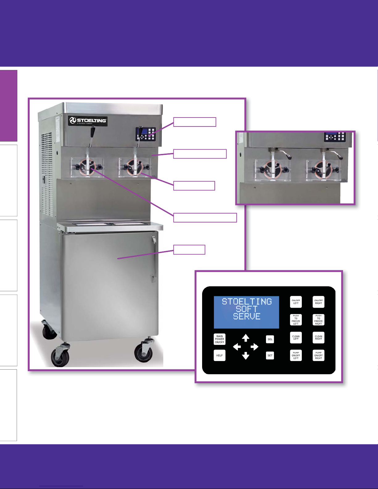
A. Parts of the U421-I2A Machine
IntelliTec2™
Spigot Handle
Front Door
Swing Gate Style Handles
MAINTENANCEPARTS TROUBLESHOOTING OPERATION INTRODUCTION
Freezing Cylinder
Cabinet
IntelliTec2™ Touchpad
The U421 has two types of spigot handles, swing gate and pull-down. The swing gate style is opened by moving the
handle to the left. The pull-down style is opened by pulling downwards.
This manual shows the pull-down handles which are self-closing. The swing gate style handles need to be closed when
fi nished dispensing.
4 U421-I2A & U431-I2A OPERATOR’S MANUAL 513713 REV.0
Page 5
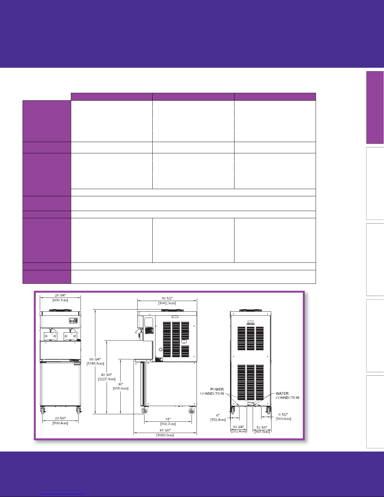
B. U421-I2A Specifi cations
U41-I2A A/C U421-I2A A/C Remote U421-I2A W/C
Dimensions
width
height
depth
Weight
Electrical
circuit ampacity
(per barrel)
overcurrent protection
device (per barrel)
Compressor
Drive Motor Two - 2 hp
Cooling
Hopper Volume Two - 8 gallon (30,28 liters)
Freezing Cylinder
Volume
Machine with crate Machine with crate Machine with crate
26-3/4’’
(67,9 cm)
68-3/4’’
(174,6 cm)
39-1/2’’
(100,3 cm)
785 lbs
(356,0 kg)
1 PH 3 PH 1 PH 3 PH 1 PH 3 PH
32A 20A
50A 30A
34’’
(86,4 cm)
78’’
(198,1 cm)
48’’
(121,9 cm)
935 lbs
(424,1 kg)
26-3/4’’
(67,9 cm)
67-3/4’’
(172,1 cm)
39-3/4’’
(101,0 cm)
760 lbs
(344,7 kg)
36A Left /
31A Right
50A Left /
45A Right
(86,4 cm)
(198,1 cm)
(121,9 cm)
908 lbs
(411,8 kg)
The machine requires one dedicated electrical circuit per barrel.
Two - 19,000 Btu/hr
Cabinet - 1,300 Btu/hr Compressor (R-134a)
Air cooled units require 6” (15,2 cm) air
space on all sides and open at the top.
Remote air cooled requires two remote
condensers and two precharged line
sets.
Two - 1.33 gallon (5,03 liters)
Section 1: Introduction
34’’
78’’
48’’
20A 32A 20A
30A 50A 30A
26-3/4’’
(67,9 cm)
67-1/2’’
(171,5 cm)
39-1/2’’
(100,3 cm)
760 lbs
(344,7 kg)
Water cooled units require 1/2” N.P.T.
water and drain fi ttings. Maximum water
pressure of 130 psi. Minimum water fl ow
rate of 3 GPM per barrel. Ideal EWT of
50°-70°F. The machine requires 6” (15,2
cm) air space on all sides for the cabinet
refrigeration system.
34’’
(86,4 cm)
78’’
(198,1 cm)
48’’
(121,9 cm)
908 lbs
(411,8 kg)
MAINTENANCE PARTSTROUBLESHOOTINGOPERATIONINTRODUCTION
513713 REV.0 U421-I2A & U431-I2A OPERATOR’S MANUAL 5
Page 6
Section 1: Introduction
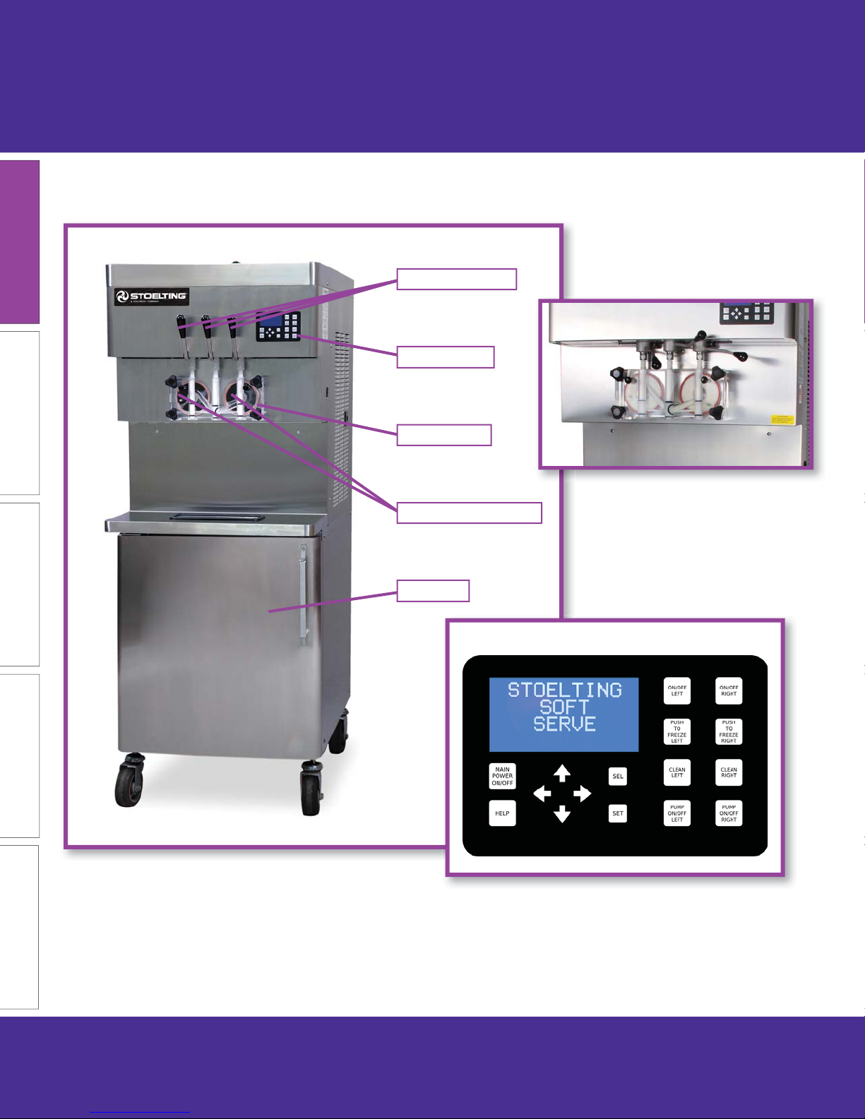
C. Parts of the U431-I2A Machine
Spigot Handle
IntelliTec2™
Front Door
Swing Gate Style Handles
MAINTENANCEPARTS TROUBLESHOOTING OPERATION INTRODUCTION
The U431 has two types of spigot handles, swing gate and pull-down. The swing gate style is opened by moving the
handle to the left. The pull-down style is opened by pulling downwards.
Freezing Cylinder
Cabinet
IntelliTec2™ Touchpad
This manual shows the pull-down handles which are self-closing. The swing gate style handles need to be closed when
fi nished dispensing.
6 U421-I2A & U431-I2A OPERATOR’S MANUAL 513713 REV.0
Page 7
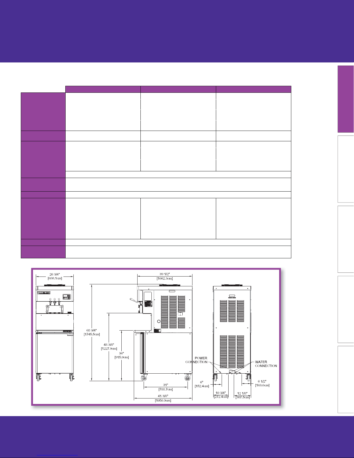
D. U431-I2A Specifi cations
U431-I2 A/C U431-I2 A/C Remote U431-I2 W/C
Dimensions
width
height
depth
Weight
Electrical
circuit ampacity
(per barrel)
overcurrent protection
device (per barrel)
Compressor
Drive Motor Two - 2 hp
Cooling
Hopper Volume Two - 8 gallon (30,28 liters)
Freezing Cylinder
Volume
Machine with crate Machine with crate Machine with crate
26-3/4''
(67,9 cm)
68-3/4''
(174,6 cm)
39-1/2''
(100,3 cm)
785 lbs
(356,0 kg)
1 PH 3 PH 1 PH 3 PH 1 PH 3 PH
32A 20A
50A 30A
34''
(86,4 cm)
78''
(198,1 cm)
48''
(121,9 cm)
935 lbs
(424,1 kg)
26-3/4''
(67,9 cm)
67-3/4''
(172,1 cm)
39-3/4''
(101,0 cm)
760 lbs
(344,7 kg)
36A Left /
31A Right
50A Left /
45A Right
The machine requires one dedicated electrical circuit per barrel.
Two - 19,000 Btu/hr
Cabinet - 1,300 Btu/hr Compressor (R-134a)
Air cooled units require 6" (15,2 cm) air
space on all sides and open at the top.
Remote air cooled requires two remote
condensers and two precharged line
sets.
Two - 1.33 gallon (5,03 liters)
Section 1: Introduction
34''
(86,4 cm)
78''
(198,1 cm)
48''
(121,9 cm)
908 lbs
(411,8 kg)
20A 32A 20A
30A 50A 30A
26-3/4''
(67,9 cm)
67-1/2''
(171,5 cm)
39-1/2''
(100,3 cm)
760 lbs
(344,7 kg)
Water cooled units require 1/2" N.P.T.
water and drain fi ttings. Maximum water
pressure of 130 psi. Minimum water fl ow
rate of 3 GPM per barrel. Ideal EWT of
50°-70°F. The machine requires 6" (15,2
cm) air space on all sides for the cabinet
refrigeration system.
34''
(86,4 cm)
78''
(198,1 cm)
48''
(121,9 cm)
908 lbs
(411,8 kg)
MAINTENANCE PARTSTROUBLESHOOTINGOPERATIONINTRODUCTION
513713 REV.0 U421-I2A & U431-I2A OPERATOR’S MANUAL 7
Page 8
Section 2: Operation
NOTE
The machine must be emptied,
disassembled, cleaned and sanitized
every 3 days or per local health code
requirements (whichever is sooner).
A. Empty the Freezing Cylinders
A.1
Turn off freezing cylinders.
A.2
MAINTENANCEPARTS TROUBLESHOOTING OPERATION INTRODUCTION
In the cab, lift the drawer latches
and pull out the drawers.
A.3
Set up cab and hoses for rinse procedure.
1. Remove the bags from the cab
and store them in a cooler.
2. Remove the three plastic bins
from the cab.
3. Remove the drawers. To
remove a drawer, pull it
out. Tilt the drawer up to
disengage the front rollers.
Pull it further out then up to
disengage the rear rollers.
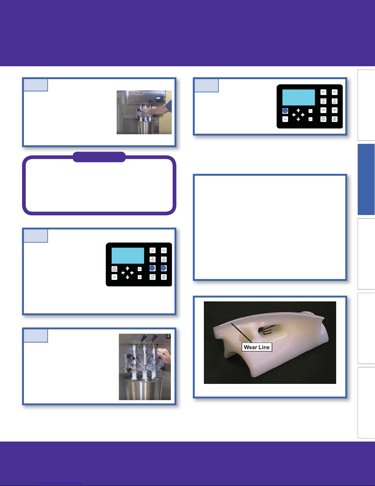
A.4
Fill a bucket with 2 gallons of cool
tap water and place the coiled
hoses with bag adapters into
the bucket.
Disconnect the bag adapters
from the bags and place caps
on the bags
NOTE
Optional: Fill the bucket with Stera Sheen
solution to make cleaning parts easier after
NOTE
disassembly.
Wire trays are located at the upper left and
right corners of the cab to store bag caps.
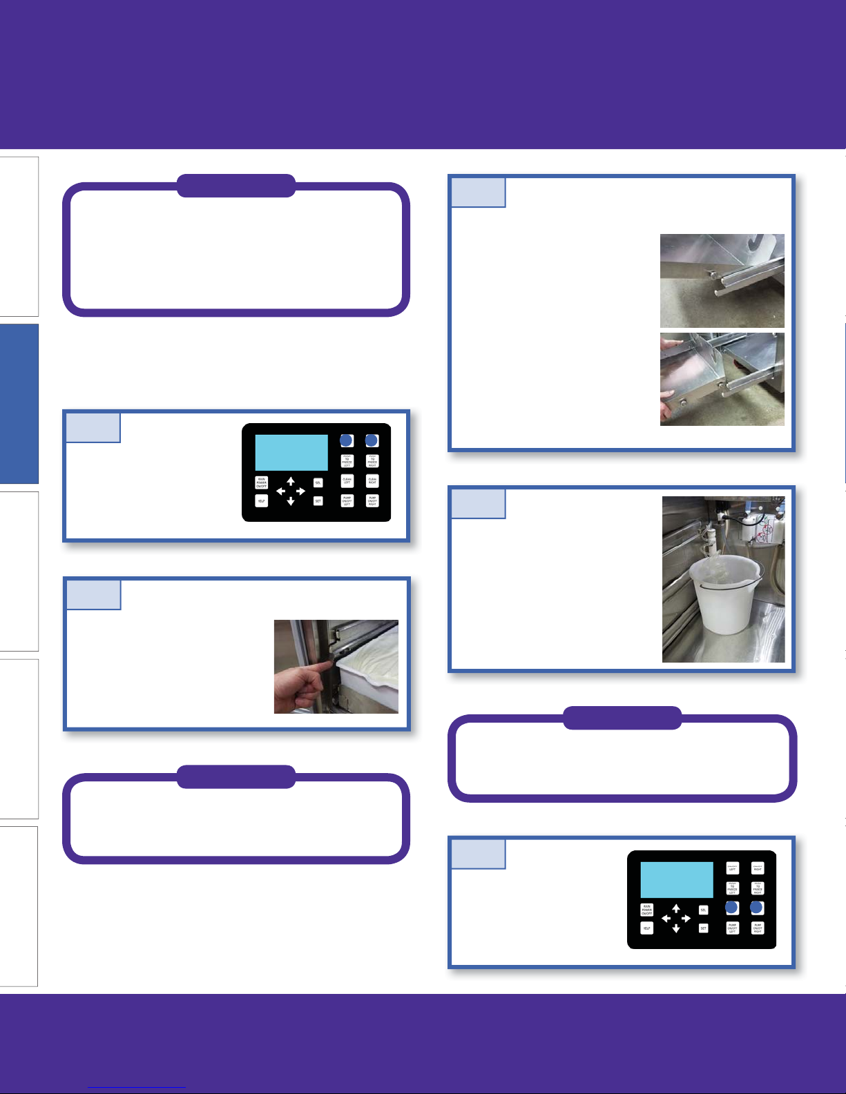
A.5
Press the Clean buttons.
Make sure the display
shows that the mix pumps
are on
8 U421-I2A & U431-I2A OPERATOR’S MANUAL 513713 REV.0
Page 9
Section 2: Operation
A.6
Open spigots to drain product
until no product is visible through
the front door. Refi ll the bucket
with water as necessary.
NOTE
If the “Clean Time Exceeded” warning
is displayed on the IntelliTec2™, turn the
freezing cylinder on and off again to clear
the warning. Press the Clean button to
resume cleaning.
A.7
Remove the buckets to help
clear any remaining liquid in
the hoses.
A.9
Press and hold the Main
Freezer Power button for
three seconds to turn off
the power.
B. Disassemble Parts
Before using the machine for the fi rst time, complete
machine disassembly, cleaning and sanitizing
procedures need to be followed. Routine cleaning
intervals and procedures must comply with the local
and state health regulations. Inspection for worn or
broken parts should be made at every disassembly
of the machine. All worn or broken parts should be
replaced to ensure safety to both the operator and the
customer and to maintain good machine performance
and a quality product. Check the wear line on the auger
fl ights on a regular basis and replace as needed.
MAINTENANCE PARTSTROUBLESHOOTINGOPERATIONINTRODUCTION
Drain the water from the
freezing cylinders and press
the Clean and Pump buttons
to stop the augers.
A.8
Open the spigots to release
any pressure in the freezing
cylinders (machines with gate
style handles).
Auger Flight Wear
513713 REV.0 U421-I2A & U431-I2A OPERATOR’S MANUAL 9
Page 10

Section 2: Operation
1. Front Door Disassembly
B.1
Remove the spigot
extensions or rosette
caps if installed.
Unscrew the knobs
on the front door and
remove the door.
B.2
Remove the front
door o-rings and
remove the spigots
from the front door.
2. Removing Auger
B.5
Remove front auger
supports and bushings
and remove the augers
from the freezing cylinders.
As the augers are being
pulled out, remove the
plastic fl ights with springs.
B.6
Wipe any remaining
lubricant off the hex end
of the auger and remove
the rear seal assembly
and o-ring. Wipe any
remaining lubricant off
the o-ring and auger.
MAINTENANCEPARTS TROUBLESHOOTING OPERATION INTRODUCTION
B.3
Remove the air bleed
valve from the front
door.
B.4
Remove all o-rings from
parts by fi rst wiping off the
lubrication using a clean
towel. Then squeeze the
o-ring upward to form a
loop. Roll the o-ring out of
the groove.
Remove the rear seal
adapter from the rear seal.
B.7
Unscrew springs
from the auger
fl ights.
NOTE
The pump hose must be replaced every
800 gallons or every two weeks, whichever
occurs fi rst. Go to Section 3 A for pump
hose replacement instructions.
10 U421-I2A & U431-I2A OPERATOR’S MANUAL 513713 REV.0
Page 11
Section 2: Operation
C. Cleaning Disassembled Parts
Disassembled parts require complete cleaning,
sanitizing and air drying before assembling. Local
and state health codes will dictate the procedure
required. Some state health codes require a four sink
process (pre-wash, wash, rinse, sanitize, air dry), while
others require a three sink process (without the prewash step). The following procedures are a general
guideline only. Consult your local and state health
codes for the procedures required in your location.
C.1
Place all parts in 90° to 110°F
(32°C to 43°C) mild detergent
water and wash thoroughly. Use
the brushes that shipped with
the machine to clean all holes in
the front door, fl ights, mix pickup
assembly, etc.
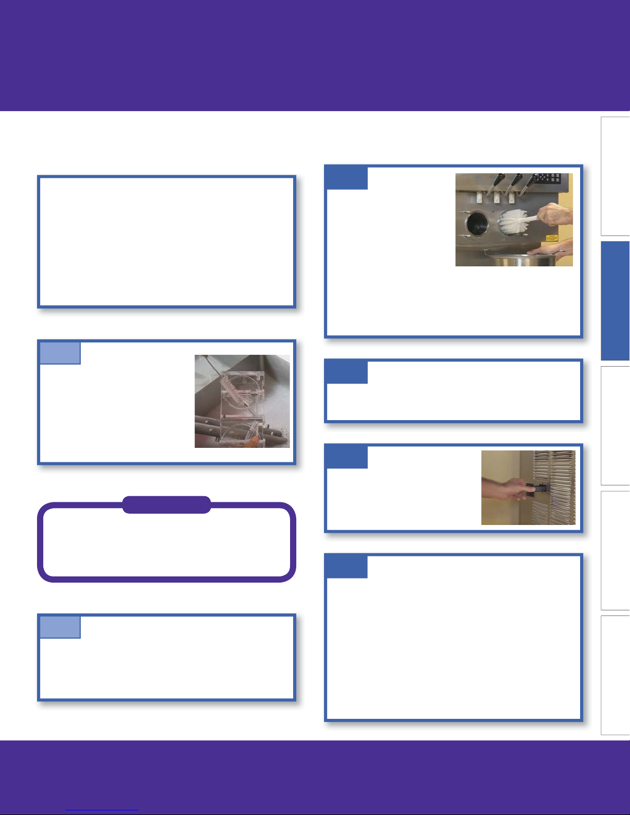
D. Cleaning the Machine
D.1
Using a detergent solution
and the large barrel
brush provided, clean
the freezing cylinders by
dipping the brush in the
solution and brushing
the inside of the freezing
cylinders.
Make sure to thoroughly clean the rear seal surfaces
on the inside of the freezing cylinders.
D.2
Wrap the brush in a clean cloth and thoroughly dry
the freezing cylinder.
D.3
MAINTENANCE PARTSTROUBLESHOOTINGOPERATIONINTRODUCTION
NOTE
Be sure to use the brushes that shipped
with the machine to properly clean the
parts.
C.2
Rinse all parts with clean 90° to 110°F (32°C to 43°C)
water. Then place all parts in a sanitizing solution for at
least 1 minute, then remove and let air dry completely
before assembling in machine.
Remove the drain tray from the
side of the machine. Remove the
drip tray from the front panel.
Clean and replace the trays.
D.4
The exterior of the machine should be kept clean at
all times to preserve the luster of the stainless steel.
A high grade of stainless steel has been used on the
machine to ease cleanup. To remove spilled or dried
mix, wash the exterior with 90° to 110°F (32°C to 43°C)
mild detergent water and wipe dry.
Do not use highly abrasive materials, as they will mar
the fi nish. A mild alkaline cleaner is recommended.
Use a soft cloth or sponge to apply the cleaner. For
best results, wipe with the grain of the steel.
513713 REV.0 U421-I2A & U431-I2A OPERATOR’S MANUAL 11
Page 12
Section 2: Operation
E. Assembling Machine
NOTE
Total Blend lubricant or equivalent must be
used when lubrication of machine parts is
specifi ed.
The USDA and FDA require that lubricants
used on food processing equipment must
be certifi ed for this use. Use lubricants
only in accordance with the manufacturer’s
instructions.
NOTE
Stoelting recommends allowing the parts
to air dry before assembling.
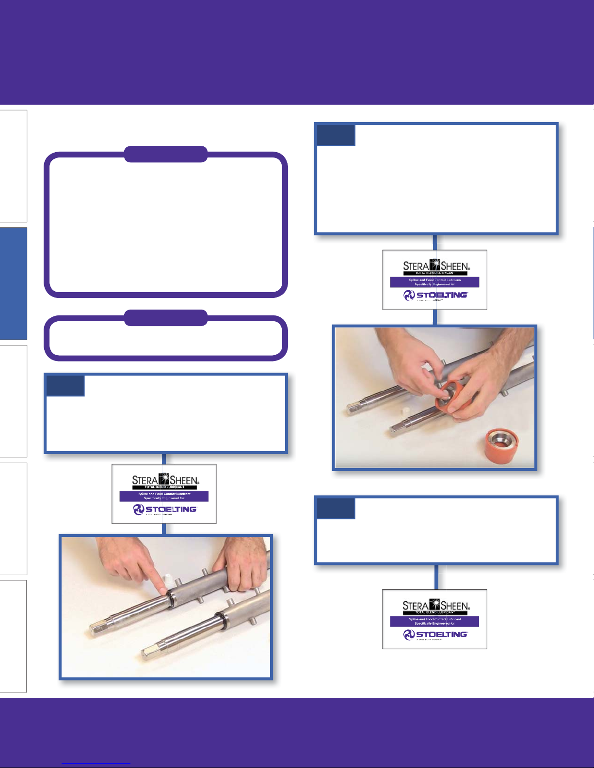
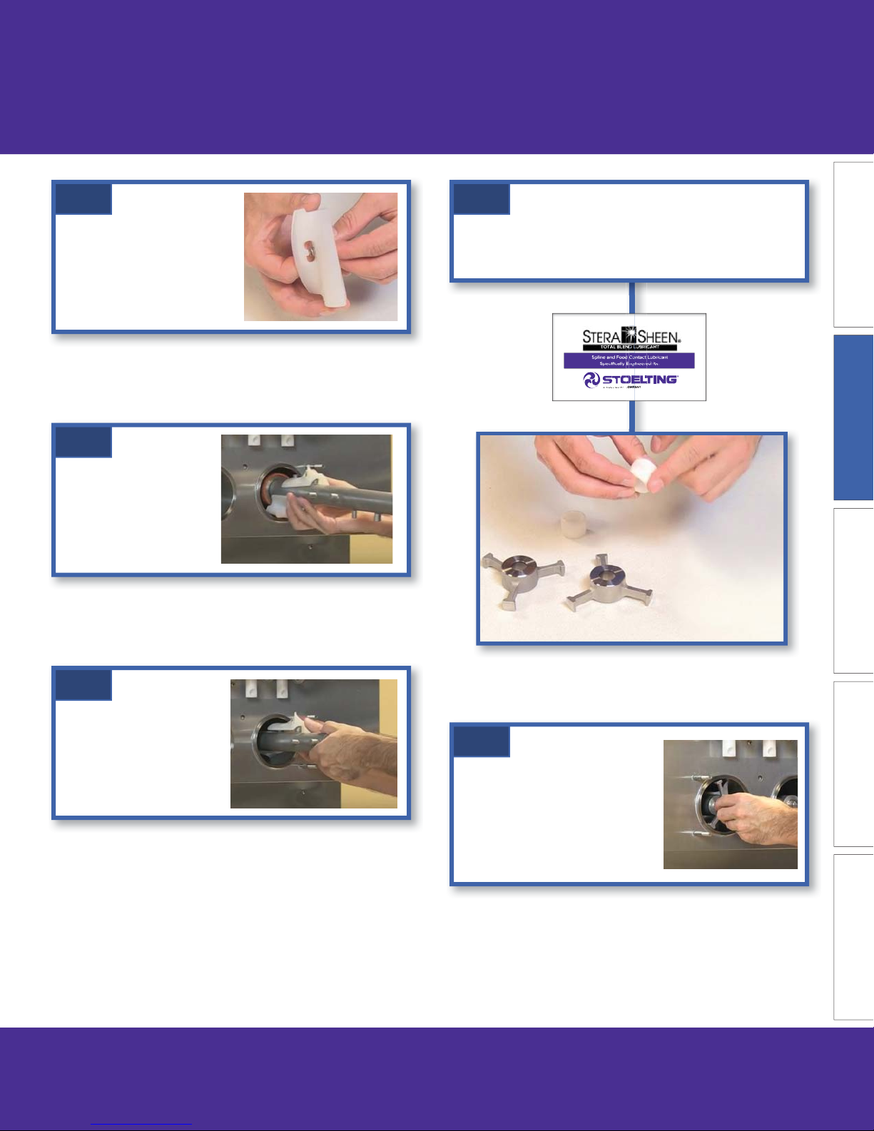
E.1
Install the rear seal o-rings onto the augers. Lubricate
the outside of the o-rings with a generous amount of
MAINTENANCEPARTS TROUBLESHOOTING OPERATION INTRODUCTION
sanitary lubricant.
E.2
Install the stainless steel adapter into the rear seal
WITHOUT LUBRICANT. Then lubricate the inside of
the adapter and install it onto the auger.
DO NOT lubricate the outside of the rear seal.
12 U421-I2A & U431-I2A OPERATOR’S MANUAL 513713 REV.0
E.3
Lubricate the hex end of the auger with Total Blend
lubricant.
Page 13
Section 2: Operation
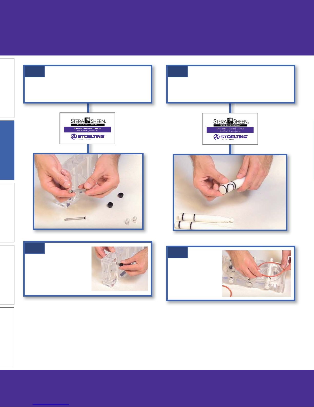
E.4
Screw the springs onto
the studs in the plastic
fl ights. The springs must
be screwed into the
fl ights completely to provide
proper compression.
E.5
Install the two plastic
fl ights onto the rear of
the auger and insert
it part way into the
freezing cylinder.
E.7
Apply a thin layer of Total Blend lubricant to the inside
and outside of the auger support bushing.
MAINTENANCE PARTSTROUBLESHOOTINGOPERATIONINTRODUCTION
E.6
Install the remaining
plastic fl ights, push the
auger into the freezing
cylinder and rotate slowly
until the auger engages
the drive shaft.
513713 REV.0 U421-I2A & U431-I2A OPERATOR’S MANUAL 13
E.8
Install the bushing onto the
auger support and install the
auger support into the front
of the auger. Rotate the auger
support so that one leg of the
support points straight up.
Page 14
Section 2: Operation
E.9
Assemble the air bleed valve o-ring onto the air bleed
valve. Position the o-ring into the groove. Apply a thin
fi lm of Total Blend lubricant to the o-ring.
E.11
Install the o-rings onto the spigot bodies and apply a
thin layer of Total Blend lubricant to the o-rings . Install
the spigot bodies through the bottom of the front door.
MAINTENANCEPARTS TROUBLESHOOTING OPERATION INTRODUCTION
E.10
Insert the air bleed valve into
the back of the front door.
Install the compression
spring onto the air bleed
valve then screw the knob
on fi nger tight.
E.12
Fit the front door
o-rings into the groove
on the rear of the front
door.
14 U421-I2A & U431-I2A OPERATOR’S MANUAL 513713 REV.0
Page 15

Section 2: Operation
E.13
Place the front door
assembly on the
mounting studs and the
push front door against
the machine carefully.
NOTE
Make sure the pins on the front door do
not touch the legs of the auger supports.
E.14
Secure the front door to
the machine by placing
the knobs on the studs
and tightening until
fi nger tight. Tighten in
a crisscross pattern.
Do not overtighten.
Proper o-ring seal can
be observed through the
transparent front door.
F. Sanitizing
Sanitizing must be done after the machine is clean and
just before the machine is fi lled with mix. Sanitizing
the night before does not ensure sanitization the next
day. However, you should always clean the machine
and parts after using it.
NOTE
The United States Department of
Agriculture and the Food and Drug
Administration require that all cleaning
and sanitizing solutions used with food
processing equipment be certifi ed for this
use
MAINTENANCE PARTSTROUBLESHOOTINGOPERATIONINTRODUCTION
When sanitizing the machine, refer to local sanitary
regulations for applicable codes and recommended
sanitizing products and procedures. The frequency of
sanitizing must comply with local health regulations.
Mix sanitizer in quantities of no less than 2 gallons
of 90°F to 110°F (32°C to 43°C) water. Allow sanitizer
to contact the surfaces to be sanitized for 5 minutes.
Any sanitizer must be used only in accordance with
the manufacturer’s instructions and to provide a 100
parts per million strength solution.
513713 REV.0 U421-I2A & U431-I2A OPERATOR’S MANUAL 15
Page 16

Section 2: Operation
F. 1
Prepare 2 gallons of sanitizing
solution for each freezing
cylinder. Following the sanitizer
manufacturer’s instructions for
preparing the sanitizing solution.
Place the coiled hoses with bag
adapters into the buckets of
sanitizer.
F. 4
After you hear the pump
shut off, press the air
bleed valves to release
the air pressure. Allow
water to fi ll the freezing
cylinders.
F. 2
Press the Main Power
button. Then press the
Pump buttons to turn the
pumps ON.
MAINTENANCEPARTS TROUBLESHOOTING OPERATION INTRODUCTION
F. 3
Check for leaks when the freezing cylinder is fi rst
pressurized with sanitizing solution.
1. Check for leaks at the front door seals.
2. Check the drain tray located in the side panel for
leaks coming from the rear of the rear auger seal.
3. Check the inside of the cab unit for leaks at the
hose connections.
F. 5
Press the CLEAN buttons to
start the augers rotating. The
IntelliTec2™ display shows a
5-minute timer.
F. 6
While the cylinders are being sanitized complete the
following:
1. Remove the buckets containing sanitizer.
2. Install spigot extensions and rosette caps (if
applicable).
16 U421-I2A & U431-I2A OPERATOR’S MANUAL 513713 REV.0
Page 17

Section 2: Operation
F. 7
After the fi ve minute timer expires,
open the spigots to drain the
sanitizing solution into a container.
When the solution has drained,
press the Pump and Clean buttons
to stop the pump and auger. Allow
the freezing cylinder to drain
completely.
F. 8
Install the three drawers. Start
with the bottom drawer.
1. Pull the drawer guides out so
they are fully extended.
2. Insert the rear rollers into the
guides.
3. Push the drawer in and insert
the front rollers into the
guides.
G. Freeze Down
Make sure the display shows the freezing cylinders
are off . If they are not, press the On/Off Left or On/Off
Right button to turn them off .
G.1
Place a bag of mix into one of the bottom drawer
sections.
NOTE
Make sure the bag opening is facing up
and towards the back of the drawer. Align
the bag corners with the corners of the
drawer so the bag is not twisted and drains
evenly.
MAINTENANCE PARTSTROUBLESHOOTINGOPERATIONINTRODUCTION
4. Place the plastic bins into the
drawers.
5. Insert the bag adapters
(connected to the coiled
hoses) into the cutouts at the
back of the drawers.
The machine is now sanitized and ready for adding mix.
513713 REV.0 U421-I2A & U431-I2A OPERATOR’S MANUAL 17
G.2
Remove the cap on the bag and
place it in the cap tray.
Page 18

Section 2: Operation
G.3
Push as much air out of
the bag as possible and
connect the bag adapter
to the bag. Make sure the
adapter is fully inserted
into the bag.
IMPORTANT TIP
Purge excess air from the bags before fully
inserting the adapters.
Excess air in the bags and hoses will
negatively aff ect product overrun and
machine operation.
G.4
G.6
Place a container under the
spigot and open the spigot
to allow the mix to fl ush out
about 8 ounces (0.23 liters) of
sanitizing solution and liquid
mix.
G.7
Allow cylinders to fi ll until
the pumps shut off . Press the
valves to release pressure
in the cylinders.
The cylinders will be fi lled
to the proper level after the
pumps shut off the second
time.
MAINTENANCEPARTS TROUBLESHOOTING OPERATION INTRODUCTION
Insert the bag adapter
into the cutout at the back
of the drawers.
Make sure the adapter is
fully inserted into the bag.
G.5
Repeat for each of the
drawer sections.
Then press the Pump buttons
to turn the pumps on.
G.8
Press the On/Off buttons
to turn on the freezing
cylinders then press the
Push to Freeze buttons.
When the product is ready,
the display will read “SERVE” or “SERVE 2”. Open the
spigot to dispense product.
G.9
If the control fl ashes and displays “Check Mix”, open
the cabinet and check the mix bags. This message is
generally displayed when air gets into the mix lines.
Operate normally to clear the error.
If “Mix Out” is displayed, check the mix levels in the
bags and replace as necessary.
18 U421-I2A & U431-I2A OPERATOR’S MANUAL 513713 REV.0
Page 19

H. Brushes for Cleaning
Section 2: Operation
208387
208467
208465
208135
208380
Part Number Where Used
208135 Freezing cylinder
208465 Front door, check valve block, pump hose
208380 Front door, pump hose, mix sensor
208467 Front door, manifold, check valve block
208485 Coiled hose
208387 Front door, pump hose, manifold, mix sensor, mix tube
MAINTENANCE PARTSTROUBLESHOOTINGOPERATIONINTRODUCTION
208485
513713 REV.0 U421-I2A & U431-I2A OPERATOR’S MANUAL 19
Page 20

Section 2: Operation
I. Lubrication Points
O-Ring
O-Ring & Hex
End of Auger
MAINTENANCEPARTS TROUBLESHOOTING OPERATION INTRODUCTION
Inside & Outside
of Bushing
ONLY Inside
Metal Adapter
All O-Rings*
* U431 spigot bodies shown, U421 has only one spigot
20 U421-I2A & U431-I2A OPERATOR’S MANUAL 513713 REV.0
Page 21

J. Pump Hose Routing
Black Cover Clamp
Black Cover Clamp
Coiled Hose
Coiled Hose
Bag Adapter
Bag Adapter
Mix Sensor
Mix Sensor
1/2" Clear Tube
1/2" Clear Tube
Section 2: Operation
Bag Adapter Cap
Bag Adapter Cap
Collection Manifold
Collection Manifold
Manifold Cap
Manifold Cap
Tan Pump Hose
Tan Pump Hose
3/8" Clear Tube
3/8" Clear Tube
Check Valve Block
Check Valve Block
MAINTENANCE PARTSTROUBLESHOOTINGOPERATIONINTRODUCTION
513713 REV.0 U421-I2A & U431-I2A OPERATOR’S MANUAL 21
Page 22

Section 3: Maintenance
A. Mix Pump Hose Replacement
NOTE
Replace pump hose every 800 gallons or
every 2 weeks, whichever occurs fi rst.
Replace the hose during the cleaning
process.
A.1
Remove the three drawers from the cab. To remove a
drawer, pull it out. Tilt the drawer up to disengage the
front rollers. Pull it further out then up to disengage
the rear rollers.
A.3
Loosen the clamps on the tan
hose at the mix sensor and check
valve block.
Disconnect the hose at both
ends.
A.4
Turn the pump on and pull the hose out of the black
cover.
MAINTENANCEPARTS TROUBLESHOOTING OPERATION INTRODUCTION
A.2
Turn the pump on and pull down
on the pickup end of the tan
hose until a few inches of tubing
is visible. The pickup end is on
the left side.
Then turn the pump off .
Then turn the pump off .
A.5
Rotate the pump rollers so one of the
rollers is at the 6:00 position.
With a brush, clean the roller
assembly with detergent water, then
with clear water.
22 U421-I2A & U431-I2A OPERATOR’S MANUAL 513713 REV.0
Page 23

Section 3: Maintenance
A.6
Connect a new length of tan hose
to the mix sensor using a clamp.
A.7
Turn the pump on and feed the other
end of the tan hose into the left side
of the black cover.
Face the natural curve of the tan hose
towards the outside of the cover to
prevent the hose from looping around
twice.
A.9
Press and hold the Pump
buttons until the pump hose
reset message appears on
the screen.
A.10
Continue normal cleaning and sanitizing procedures.
MAINTENANCE PART STROUBLESHOOTINGOPERATIONINTRODUCTION
A.8
As the hose feeds through the cover, orient the sensor
at an angle so the sensor wire does not interfere with
the drawer closing and is not obstructed by the other
hoses.
Then turn the pump off .
Connect the hose to the check valve block.
513713 REV.0 U421-I2A & U431-I2A OPERATOR’S MANUAL 23
Page 24

Section 3: Maintenance
B. Mix Pump Hose Cleaning
NOTE
Any cleaning procedure must always be
followed by sanitizing before fi lling the
machine with mix.
The mix pump is approved for CIP (clean-in-place). It
is thoroughly cleaned when the cleaning solution is
pumped through the machine. To ensure CIP has been
properly performed, the pump should be completely
disassembled and cleaned every 7 days.
WARNING
1. Disassembly and Coiled Hose
Cleaning
B.1
Remove the three drawers from the cab. To remove a
drawer, pull it out. Tilt the drawer up to disengage the
front rollers. Pull it further out then up to disengage
the rear rollers.
B.2
Disconnect the bag adapters from
the coiled hoses.
Pull the coiled hoses so they are
straight. Then use detergent water
with the long brush to clean the hoses.
MAINTENANCEPARTS TROUBLESHOOTING OPERATION INTRODUCTION
Hazardous Moving Parts
Revolving pump head can grab, mangle, and cause
serious crushing injury. Make sure the display shows
the freezing cylinders and pump are off . If they are
not, press the On/Off button and Pump button to turn
them off .
System Under Pressure
Never disconnect hoses from the machine or the pump
without fi rst opening the spigot to relieve pressure.
CAUTION
NOTE
Rotate the coiled hose as it is stretched to
help straighten it out.
B.3
Lift the collection manifold upwards
then tilt it back to detach it from the
bracket.
The manifold may need to be
rotated so the metal stem clears
the bracket.
24 U421-I2A & U431-I2A OPERATOR’S MANUAL 513713 REV.0
Page 25

Section 3: Maintenance
B.4
Disconnect the wires from the
low mix sensor.
B.5
Turn the pump on and pull down
on the pickup end of the tan
hose until a few inches of tubing
is visible. The pickup end is on
the left side.
Then turn the pump off .
Loosen the clamp on the tan hose
and disconnect the hose at the
low mix sensor.
B.6
B.8
Loosen the clamp on the mix tube at the top of the
cab and remove the hose from the tube.
B.9
Remove the two o-rings from the
base of the check valve block.
B.10
Remove the hose assemblies from the cab.
Loosen all clamps and disconnect all hoses including
the following:
• Bag adapters
• Mix collection manifold
• Low mix sensor
• Check valve block
MAINTENANCE PART STROUBLESHOOTINGOPERATIONINTRODUCTION
Turn the mix pump on and pull the tan house out of
the black cover clamp then turn the mix pump off .
B.7
Unfasten the wire clamp on the
check valve block by swinging
the clamp to the right. Remove
the check valve.
513713 REV.0 U421-I2A & U431-I2A OPERATOR’S MANUAL 25
2. Inspect and Cleaning
B.11
Inspect all the parts for wear and replace as necessary.
B.12
Thoroughly clean the parts with 90° to 110°F detergent
water and brushes provided. Rinse with clean, 90° to
110°F water.
Page 26

Section 3: Maintenance
y
B.13
Wash the mix tube and the check
valve base in the cabinet with the
detergent water and brushes.
Rinse with clean, 90° to 110°F
water.
3. Reassembly
3. Reassembl
3. Reassembly
B.14
Connect the coiled hoses to
the bag adapters and to the mix
collection manifold.
Connect the clear hose to the
bottom of the manifold.
MAINTENANCEPARTS TROUBLESHOOTING OPERATION INTRODUCTION
B.17
Turn the pump on and feed the
tan hose into the left side of the
black cover clamp.
NOTE
Face the natural curve of the tan hose
towards the outside of the cover to prevent
the hose from looping around twice.
B.18
As the hose feeds through the cover, orient the sensor
at an angle so the sensor wire does not interfere with
the drawer closing and is not obstructed by the other
hoses.
B.15
Install the manifolds into the
bracket.
B.16
Connect the tan hose to the low mix sensor.
26 U421-I2A & U431-I2A OPERATOR’S MANUAL 513713 REV.0
Then turn the pump off .
B.19
Connect the hose from the
bottom of the manifold to the
low mix sensor.
Page 27

Section 3: Maintenance
B.20
Connect the tan hose to the bottom of the check
valve block. The bottom of the block has the smaller
hose connector.
B.21
Install the o-rings onto the base of the check valve
block. Apply a thin layer of sanitary lubricant to the
o-rings.
B.22
Connect the clear hose to the top of the check valve
block and tighten the clamp.
Insert the other end of the clear hose onto the mix
tube at the top of the cabinet. Do not tighten the clamp
until the check valve block is installed.
B.23
Install the check valve into the
block and secure the block with
the wire clamp. Make sure the
rubber check valve is installed in
the bottom seat of the assembly.
MAINTENANCE PART STROUBLESHOOTINGOPERATIONINTRODUCTION
B.24
Adjust the clear hose so that it is not kinked and tighten
the clamp holding the hose to the mix tube.
B.25
Connect the low mix sensor wires
to the sensor
B.26
Sanitize assembled machine as per instructions
outlined in Section 2 F.
513713 REV.0 U421-I2A & U431-I2A OPERATOR’S MANUAL 27
Page 28

Section 3: Maintenance
C. Fine Consistency Adjustment
Product consistency can be adjusted on the Fine
Consistency Adjustment Screen.
C.1
From the Current
Status screen, press
the left arrow button to
access the password
screen.
Press the right arrow
then the SEL button.
C.2
C.3
Press the SET button to save the changes.
Press the SEL button to toggle between freezing
cylinders.
C.4
Press the left arrow button when done to return to the
Current Status screen.
MAINTENANCEPARTS TROUBLESHOOTING OPERATION INTRODUCTION
Press the SET
button on the
Fine Consistency
Adjustment screen.
And use the arrows
to change the value.
Increase the value for higher consistency (thicker).
Change the +/- symbol to “-” and adjust the value for
lower consistency (thinner) product.
Make adjustments in increments of 5 for best results.
Allow 3-4 draws or 30 minutes for the changes to
take eff ect.
28 U421-I2A & U431-I2A OPERATOR’S MANUAL 513713 REV.0
Page 29

Section 3: Maintenance
Daily Procedures
D. Daily Procedures - Night E. Daily Procedures - Morning
D.1
Remove the drip tray from
the front panel. Clean the
tray and reinstall it.
D.2
Remove the spigot extensions. Clean and sanitize
them and let them air dry.
D.3
Clean the underside of the clear front door and the
exposed portion of the spigots with mild detergent
water and then with sanitizing solution.
E.1
Clean the underside of the clear front door and the
exposed portion of the spigots with brushes and a
mild detergent water and then with sanitizing solution.
E.2
Install the spigot extensions.
E.3
MAINTENANCE PART STROUBLESHOOTINGOPERATIONINTRODUCTION
Check the mix level of the mix bags in the cab.
Add new mix bags as necessary.
D.4
Wipe the exterior clean with a mild detergent water to
remove spilled or dried mix and wipe dry.
513713 REV.0 U421-I2A & U431-I2A OPERATOR’S MANUAL 29
E.4
Press the Push To Freeze
button to start freezing the
product.
When the product is ready,
the display will read “SERVE”
or “SERVE 2”. Open the
spigot to dispense product.
Page 30

Section 4: Troubleshooting
Product is Too
Increase the fine
consistency.
Is the product still
MAINTENANCEPART S TROUBLESHOOTING OPERATION INTRODUCTION
too Soft?
Soft
Yes
Is there an air flow
restriction around
the machine?
Product is Too
Firm
Decrease the fine
consistency.
Is the product still
too firm?
No
Continue normal
operation.
No
Yes
Contact your authorized
Stoelting distributor for
further assistance
No
Yes
Move anything blocking
the louvered panels and
make sure there is
enough air clearance
around the machine.
Continue normal
operation.
30 U421-I2A & U431-I2A OPERATOR’S MANUAL 513713 REV.0
Yes
Is the problem
fixed?
No
Contact your authorized
Stoelting distributor for
further assistance
Page 31

Section 4: Troubleshooting
If an error code appears on the machine complete the steps on the following pages before calling your authorized
Stoelting distributor. Oftentimes the issues can be resolved using new/fresh product in a clean and sanitized machine.
Any Error Code
on IntelliTec2™
Go to the flow chart
for the error code
Make sure there is no excess air in
the mix bags.
Error Code (E2)
High Torque
Make sure the bags of mix are
supplying the freezing cylinder, fully
thawed and connected properly.
Error Code (E3) Run Time
Air-Cooled Machines
Turn the power off using the Main Freezer
Power button. Make sure the electrical plug is
secure in the outlet. Turn the power back on.
Error Code (E3) Run Time
Water-Cooled Machines
MAINTENANCE PARTSTROUBLESHOOTINGOPERATIONINTRODUCTION
Freeze the product and test.
Error Code (E9) High
Pressure Cutout
Air-Cooled Machines
Is there still an
error code?
No
Continue normal operation.
513713 REV.0 U421-I2A & U431-I2A OPERATOR’S MANUAL 31
Yes
Error Code (E9) High
Pressure Cutout
Water-Cooled Machines
Contact your authorized
Stoelting distributor for further
assistance for all other codes.
Page 32

Section 4: Troubleshooting
E2 Common Causes
• Excess air in the freezing cylinder
due to air in the mix bags.
• Improper adjustments to the
IntelliTec2™ control.
No
Error Code (E2)
High Torque
Is there liquid
product in the
freezing cylinder?
Yes
MAINTENANCEPART S TROUBLESHOOTING OPERATION INTRODUCTION
Allow product to thaw, then
disassemble and check
condition of the parts.
Replace as necessary
Continue normal operation.
Contact your authorized Stoelting
distributor for further assistance
Is the problem
fixed?
Yes No
Contact your authorized Stoelting
distributor for further assistance
32 U421-I2A & U431-I2A OPERATOR’S MANUAL 513713 REV.0
Page 33

Error Code (E3)
Run Time
Air-Cooled Machines
Is there an air flow
restriction around
the machine?
Yes
Section 4: Troubleshooting
Move anything blocking
the louvered panels and
make sure there is
enough air clearance
around the machine.
E3 Common Causes
• Blocked airfl ow around machine or
dirty air fi lter.
• Excess air in the freezing cylinder
due to air in the mix bags.
• Pump turned off or not operating
• Improper adjustments to the
IntelliTec2™ control.
Is the problem
fixed?
Yes
MAINTENANCE PARTSTROUBLESHOOTINGOPERATIONINTRODUCTION
No
Does the error
occur after the first
freezing cycle?
No
Contact your authorized
Stoelting distributor for
further assistance
Yes
Disassemble machine
and reassemble
following the steps in the
operators manual.
No
Is the problem
fixed?
No
Continue normal operation.
Yes
513713 REV.0 U421-I2A & U431-I2A OPERATOR’S MANUAL 33
Page 34

Section 4: Troubleshooting
Error Code (E3)
Run Time
Water-Cooled Machines
Is the water or
glycol system
turned off?
No
Are the water or
glycol lines kinked
or damaged?
Yes Turn the system on.
No
Repair or replace the
lines.
Is the problem
fixed?
E3 Common Causes
• Lack of water/glycol fl ow.
• Excess air in the freezing cylinder
due to air in the mix bags.
• Pump turned off or not operating
• Improper adjustments to the
IntelliTec2™ control.
Yes
Is the problem
fixed?
YesYes
MAINTENANCEPART S TROUBLESHOOTING OPERATION INTRODUCTION
Does the error
occur after the first
freezing cycle?
Contact your authorized
Stoelting distributor for
further assistance
No
No
Yes
Disassemble machine
and reassemble
following the steps in the
operators manual.
No
Is the problem
fixed?
No
Yes
Continue normal operation.
34 U421-I2A & U431-I2A OPERATOR’S MANUAL 513713 REV.0
Page 35

Error Code (E9)
High Pressure Cutout
Air-Cooled Machines
Is there an air flow
restriction around
the machine?
Yes
Section 4: Troubleshooting
Move anything blocking
the louvered panels and
make sure there is
enough air clearance
around the machine.
E9 Common Causes
• Blocked airfl ow around machine or
dirty air fi lter.
• External heat source
Is the problem
fixed?
Yes
No
Check for an exterior heat source
from equipment. Examples include:
• Ice Machine
• Grill
• Hot Dog Steamer
Is there an
exterior heat
source?
No
Contact your authorized
Stoelting distributor for
further assistance
Yes
Move equipment that
increases the ambient
temperature away from
the machine.
No
Is the problem
fixed?
No
Continue normal operation.
MAINTENANCE PARTSTROUBLESHOOTINGOPERATIONINTRODUCTION
Yes
513713 REV.0 U421-I2A & U431-I2A OPERATOR’S MANUAL 35
Page 36

Section 4: Troubleshooting
Error Code (E9)
High Pressure Cutout
Water-Cooled Machines
E9 Common Causes
• Lack of water/glycol fl ow.
MAINTENANCEPART S TROUBLESHOOTING OPERATION INTRODUCTION
Are the water or
glycol lines kinked
Is the water or
glycol system
turned off?
No
or damaged?
No
Repair or replace the
lines.
Is the problem
fixed?
No
Is the problem
fixed?
No
YesYes Turn the system on.
YesYes
Contact your authorized
Stoelting distributor for
further assistance
36 U421-I2A & U431-I2A OPERATOR’S MANUAL 513713 REV.0
Continue normal operation.
Page 37

Section 5: Replacement Parts
A.1
2208137
2208137
2208193
2208193
232025
232025
Cab Tubing
756236
756236
264235
264235
2208043
2208043
234235
234235
2208169
2208169
264241
264241
264235
264235
232024
232024
756088
756088
756079
756079
264241
264241
264235
264235
756204
756204
694247
694247
2206611
2206611
762256
762256
624644
624644
624619
624619
MAINTENANCE PART STROUBLESHOOTINGOPERATIONINTRODUCTION
Part Number Description Quantity
232024 Cap - Manifold 4
232025 Cap - Bag Adapter 4
264235 Clamp - Metal (1/4” ID Tubing) 264241 Clamp - Metal (1/2” ID Tubing) 624616-5 O-Ring - Check Valve Block - Lower - Black (5 Pack) 2
624644-5 O-Ring - Check Valve Block - Upper - Black (5 Pack) 2
694247 Spring - Check Valve 2
756079 Tubing - 3/8” ID - Clear 2
756088 Tubing - 1/2” ID - Clear 2
756204 Tubing - 1/4” ID - Pump (50’ Box Only) (Per Inch) 756204-24 Tubing - 1/4” ID - Pump (Pre-Cut 24” Piece) 2
756236 Tubing - 1/4” I.D. - Coiled - Blue 6
762256 Check Valve 2
2206611 Check Valve Block 2
2208137 Mix Bag Adapter (Stainless Steel) 6
2208169 Manifold - Mix Collection (Manifold Only) 2
2208043 Sensor - Mix 2
513713 REV.0 U421-I2A & U431-I2A OPERATOR’S MANUAL 37
Page 38

Section 5: Replacement Parts
A.2
694200
694200
482004
482004
2204252
2204252
624598
624598
MAINTENANCEPART S TROUBLESHOOTING OPERATION INTRODUCTION
U421-I2A Auger Shaft & Front Door Parts
667868
381804
381804
2183106
2183106
2187696
2187696
Part Number Description Quantity
149003 Bushing - Front Auger Support 2
381804 Auger Flight 12
482004 Knob (Air Bleed Valve) 2
482019 Knob - Front Door (Black) 4
624520 O-Ring - Air Bleed Valve - Black 2
624598 O-Ring - Spigot - Black 4
624678 O-Ring - Rear Seal - Black 2
625133 O-Ring - Front Door - Black 2
667868 Seal - Rear Auger (Orange) 2
694200 Spring - Air Bleed Valve 2
694255 Spring - Auger Flight 12
1151859 Adapter - Rear Seal (Code 1) 2
2183106 Valve - Air Bleed 2
2104552 Support - Front Auger 2
2187696 Front Door 2
2204252 Spigot Body 2
4151178 Auger Shaft 2
624520
624520
482019
482019
2104552
2104552
625133
625133
149003
149003
4151178
4151178
694255
694255
624678
624678
667868
1151859
1151859
38 U421-I2A & U431-I2A OPERATOR’S MANUAL 513713 REV.0
Page 39

Section 5: Replacement Parts
A.3
482004
482004
694200
694200
624664
624664
624614
624614
U431-I2A Auger Shaft & Front Door Parts
381804
381804
2110116
2110116
694255
624520
624520
2187811
2187811
Part Number Description Quantity
149003 Bushing - Front Auger Support 2
381804 Auger Flight 12
482004 Knob (Air Bleed Valve) 2
482019 Knob - Front Door (Black) 4
624520 O-Ring - Air Bleed Valve - Black 2
624598 O-Ring - Outside Spigot - Black 4
624614 O-Ring - Top & Bottom Center Spigot - Black 2
624664 O-Ring - Middle Center Spigot - Black 1
624678 O-Ring - Rear Seal - Black 2
625133 O-Ring - Front Door - Black 2
667868 Seal - Rear Auger (Orange) 2
694200 Spring - Air Bleed Valve 2
694255 Spring - Auger Flight 12
1151859 Adapter - Rear Seal (Code 1) 2
2104552 Support - Front Auger 2
2110116 Valve - Air Bleed 2
2177427 Front Door 1
2187811 Spigot Body - Center 1
2187812 Spigot Body - Outer 2
4151178 Auger Shaft 2
482019
482019
2104552
2104552
2187812
2187812
624598
624598
625133
625133
149003
149003
2177427
2177427
694255
4151178
4151178
624678
624678
1151859
1151859
667868
667868
MAINTENANCE PART STROUBLESHOOTINGOPERATIONINTRODUCTION
513713 REV.0 U421-I2A & U431-I2A OPERATOR’S MANUAL 39
Page 40

40 U421-I2A & U431-I2A OPERATOR’S MANUAL 513713 REV.0
Page 41

513713 REV.0 U421-I2A & U431-I2A OPERATOR’S MANUAL 41
Page 42

42 U421-I2A & U431-I2A OPERATOR’S MANUAL 513713 REV.0
Page 43

DOMESTIC WARRANTY
(Including Mexico)
SOFT SERVE / SHAKE EQUIPMENT
1. Scope:
PW Stoelting, L.L.C. (“Stoelting”) warrants to the first user (the “Buyer”) that the freezing cylinders,
hoppers, compressors, drive motors, speed reducers, and augers of Stoelting soft serve / shake
equipment will be free from defects in materials and workmanship under normal use and proper
maintenance appearing within five (5) years, and that all other components of such equipment
manufactured by Stoelting will be free from defects in material and workmanship under normal use
and proper maintenance appearing within twelve (12) months after the date that such equipment is
originally installed.
2. Disclaimer of Other Warranties:
THIS WARRANTY IS EXCLUSIVE; AND STOELTING HEREBY DISCLAIMS ANY
IMPLIED WARRANTY OF MERCHANTABILITY OR FITNESS FOR PARTICULAR
PURPOSE.
3. Remedies:
Stoelting’s sole obligations, and Buyer’s sole remedies, for any breach of this warranty shall be the
repair or (at Stoelting’s option) replacement of the affected component at Stoelting’s plant in Kiel,
Wisconsin, or (again, at Stoelting’s option) refund of the purchase price of the affected equipment,
and, during the first twelve (12) months of the warranty period, deinstallation/reinstallation of the
affected component from/into the equipment. Those obligations/remedies are subject to the
conditions that Buyer (a) signs and returns to Stoelting, upon installation, the Start-Up and Training
Checklist for the affected equipment, (b) gives Stoelting prompt written notice of any claimed breach
of warranty within the applicable warranty period, and (c) delivers the affected equipment to Stoelting
or its designated service location, in its original packaging/crating, also within that period. Buyer shall
bear the cost and risk of shipping to and from Stoelting’s plant or designated service location.
4. Exclusions and Limitations:
This warranty does not extend to parts, sometimes called “wear parts”, which are generally expected
to deteriorate and to require replacement as equipment is used, including as examples but not
intended to be limited to o-rings, auger flights, auger seals, auger support bushings, and drive belts.
All such parts are sold
AS IS.
Further, Stoelting shall not be responsible to provide any remedy under this warranty with respect to
any component that fails by reason of negligence, abnormal use, misuse or abuse, faulty repair made
by others, use with parts or equipment not manufactured or supplied by Stoelting, any modification or
alteration of any parts or equipment, or damage in transit.
The use of this equipment as a rental asset will negate all warranties associated with the equipment.
THE REMEDIES SET FORTH IN THIS WARRANTY SHALL BE THE SOLE LIABILITY
STOELTING AND THE EXCLUSIVE REMEDY OF BUYER WITH RESPECT TO
EQUIPMENT SUPPLIED BY STOELTING; AND IN NO EVENT SHALL STOELTING
BE LIABLE FOR ANY INCIDENTAL OR CONSEQUENTIAL DAMAGES, INCLUDING
AS EXAMPLES BUT NOT INTENDED TO BE LIMITED TO DOWNTIME, OVERHEAD,
MATERIALS, AND PERFORMANCE PENALTIES, WHETHER FOR BREACH OF
WARRANTY OR OTHER CONTRACT BREACH, NEGLIGENCE OR OTHER TORT,
OR ON ANY STRICT LIABILITY THEORY.
513713 REV.0 U421-I2A & U431-I2A OPERATOR’S MANUAL 43
SFWARR-013
Revision 05
Page 1 of 1
Page 44

 Loading...