

Page 1

Model U431
SERVICE MANUAL
Manual No. 513572 Rev.5
Page 2

Page 3

This manual provides basic information about the machine. Instructions and suggestions are
given covering its operation and care.
The illustrations and specifi cations are not binding in detail. We reserve the right to make
changes to the machine without notice, and without incurring any obligation to modify or provide new parts for machines built prior to date of change.
DO NOT ATTEMPT to operate the machine until instructions and safety precautions in this
manual are read completely and are thoroughly understood. If problems develop or questions
arise in connection with installation, operation, or servicing of the machine, contact Stoelting.
stoeltingfoodservice.com
Stoelting Foodservice Equipment
502 Highway 67
Kiel, WI 53042-1600
U.S.A.
Main Tel: 800.558.5807
Fax: 920.894.7029
Customer Service: 888.429.5920
Fax: 800.545.0662
Email: foodservice@stoelting.com
© 2014 PW Stoelting, LLC
Page 4

A Few Words About Safety
Safety Information
Read and understand the entire manual before
operating or maintaining Stoelting equipment.
This manual provides the operator with information
for the safe operation and maintenance of Stoelting
equipment. As with any machine, there are hazards
associated with their operation. For this reason safety
is emphasized throughout the manual. To highlight
specifi c safety information, the following safety defi ni-
tions are provided to assist the reader.
The purpose of safety symbols is to attract your attention to possible dangers. The safety symbols, and
their explanations, deserve your careful attention
and understanding. The safety warnings do not by
themselves eliminate any danger. The instructions
or warnings they give are not substitutes for proper
accident prevention measures.
If you need to replace a part, use genuine Stoelting
parts with the correct part number or an equivalent
part. We strongly recommend that you do not use
replacement parts of inferior quality.
Safety Alert Symbol:
This symbol Indicates danger, warning or caution.
Attention is required in order to avoid serious personal injury. The message that follows the symbol
contains important information about safety.
Signal Word:
Signal words are distinctive words used throughout
this manual that alert the reader to the existence and
relative degree of a hazard.
WARNING
The signal word “WARNING” indicates a potentially
hazardous situation, which, if not avoided, may result
in death or serious injury and equipment/property
damage.
CAUTION
The signal word “CAUTION” indicates a potentially
hazardous situation, which, if not avoided, may result
in minor or moderate injury and equipment/property
damage.
CAUTION
The signal word “CAUTION” not preceded by the
safety alert symbol indicates a potentially hazardous
situation, which, if not avoided, may result in equipment/property damage.
NOTE (or NOTICE)
The signal word “NOTICE” indicates information or
procedures that relate directly or indirectly to the
safety of personnel or equipment/property.
Page 5

TABLE OF CONTENTS
Sect. 1 INTRODUCTION .................................................................................... 1
1.1 Description.............................................................................................. 1
1.2 Specifications.......................................................................................... 1
Sect. 2 INST ALLATION INSTRUCTIONS .......................................................... 3
2.1 Safety Precautions .................................................................................. 3
2.2 Shipment & Transit .................................................................................. 4
2.3 Freezer Installation................................................................................... 4
2.4 Installing Permanent Wiring...................................................................... 4
2.5 Mix Pump (Serial #0 thru 17977).............................................................. 5
2.6 Mix Pump (Serial #17978 and up)............................................................ 8
Sect. 3 INITIAL SET -UP AND OPERATION....................................................... 11
3.1 Safety Precautions .................................................................................. 11
3.2 Operating Controls and Indicators............................................................ 11
3.3 Important Information Regarding Cleaning and Sanitizing......................... 13
3.4 Disassembly of Freezer Parts.................................................................. 14
3.5 Cleaning Disassembled Parts ................................................................. 15
3.6 Sanitize Freezer Parts ............................................................................. 15
3.7 Cleaning the Freezer ............................................................................... 16
3.8 Assembling Freezer ................................................................................ 16
3.9 Sanitizing ................................................................................................ 18
3.10 Initial Freeze Down and Operation ........................................................... 18
3.11 Mix Information ........................................................................................ 19
3.12 Operation of Mix Pump ............................................................................ 20
3.13 Mix Pump Cleaning ................................................................................. 20
3.14 Disassembly and Inspection of Removable Parts..................................... 20
Sect. 4 MAINTENANCE INSTRUCTIONS......................................................... 23
4.1 Freezer Adjustment.................................................................................. 23
4.2 Product T emperature Adjustment ............................................................. 23
4.3 Overrun Adjustment..................................................................................23
4.4 Mix Pump Hose Reposition ..................................................................... 24
4.5 Mix Pump Hose Replacement.................................................................. 24
4.6 Cab T emperature Adjustment................................................................... 24
4.7 Drive Belt T ension Adjustment.................................................................. 25
4.8 Condenser Cleaning (Air-Cooled Freezers)............................................. 25
4.9 Preventative Maintenance........................................................................ 25
4.10 Extended S torage.................................................................................... 26
4.11 Freezer Reference Photos....................................................................... 27
Page 6

TABLE OF CONTENTS
Sect. 5 REFRIGERA TION SYSTEM .................................................................. 31
5.1 Refrigeration System ............................................................................... 31
5.2 Compressor ............................................................................................ 31
5.3 Condenser .............................................................................................. 32
5.4 Evaporator .............................................................................................. 32
5.5 Cab Unit .................................................................................................. 34
Sect. 6 ELECTRICAL CONTROL SYSTEM ...................................................... 35
6.1 Control System ........................................................................................ 35
6.2 Current Sensor ........................................................................................ 36
6.3 Contactors............................................................................................... 36
6.4 Drive Motor.............................................................................................. 36
Sect. 7 MAJOR COMPONENT REMOVAL AND INSTALLATION..................... 37
7.1 Preparation for Component Removal....................................................... 37
7.2 Cooling Fan Motor Removal .................................................................... 37
7.3 Drive Motor Removal ............................................................................... 37
7.4 Gear Box Removal .................................................................................. 37
7.5 Compressor Removal.............................................................................. 38
7.6 Compressor Installation ........................................................................... 38
7.7 Gearbox Installation ................................................................................. 3 9
7.8 Drive Motor Installation............................................................................. 39
7.9 Condenser Fan Motor Installation (Air-Cooled)......................................... 39
7.10 Final Assembly of Freezer ....................................................................... 40
Sect. 8 TROUBLESHOOTING ........................................................................... 41
8.1 Troubleshooting - Freezer ........................................................................ 41
8.2 Refrigeration Drawings ............................................................................ 42
8.3 Troubleshooting - Mix Pump..................................................................... 44
8.4 Troubleshooting the Challenger T emperature Control and Sensor............. 46
Sect. 9 REPLACEMENT PARTS INFORMATION ............................................. 53
9.1 Replacement Parts Information ................................................................ 53
General Order Advice.............................................................................. 75
Page 7

ILLUSTRATIONS
Figure 1 Model U431 Freezer..............................................................1
Figure 2 Specifications........................................................................1
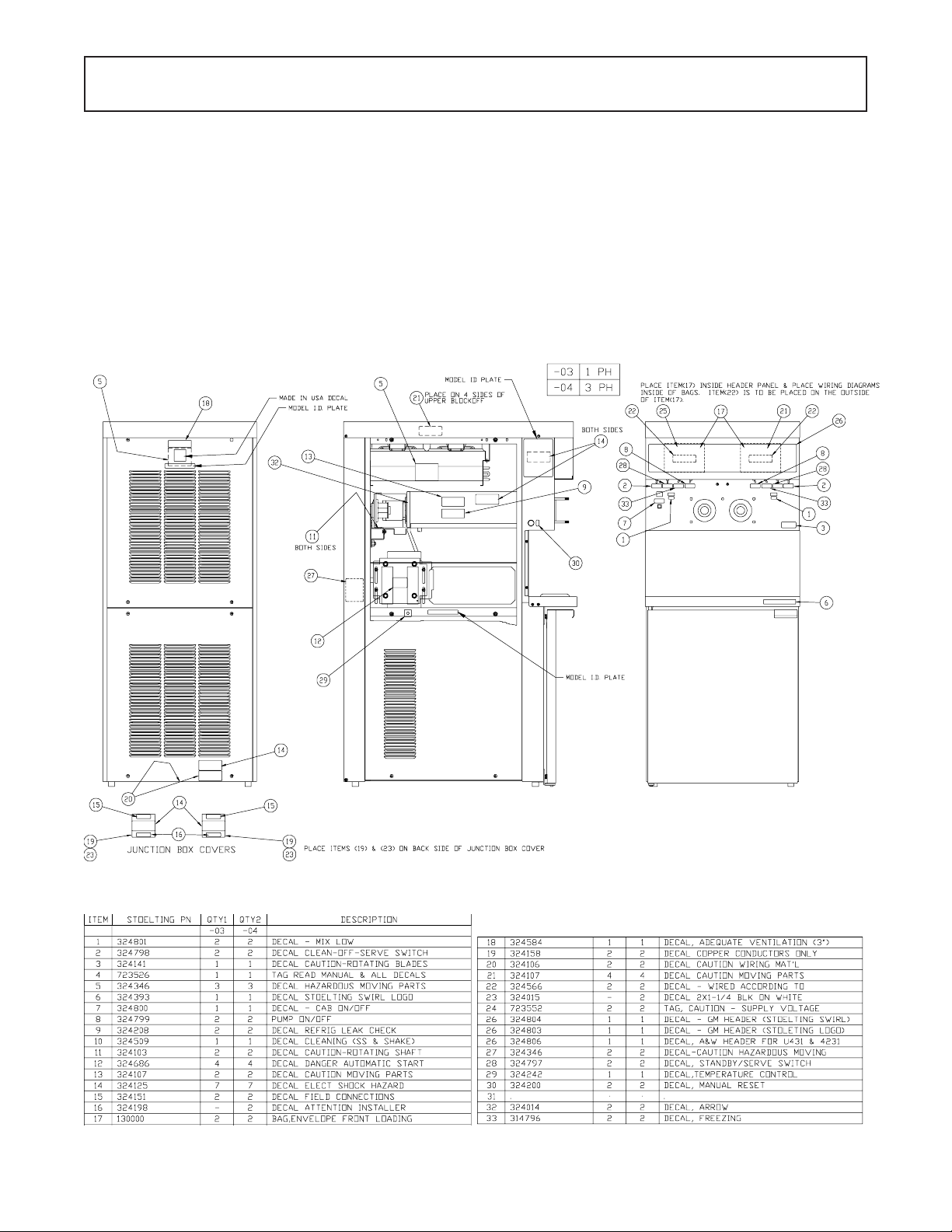
Figure 3 Decal Label Locations ...........................................................3
Figure 4 Water/Electrical Connections .................................................4
Figure 5 Auger Rotation.......................................................................4
Figure 6 Mix Hose Installation...............................................................5
Figure 7 Mix Pump...............................................................................6
Figure 8 4 Way Tee .............................................................................7
Figure 9 Mix Inlet Tube & Probe Assy. Clip...........................................7
Figure 10 Hose Holder...........................................................................7
Figure 11 Mix Hose Installation...............................................................8
Figure 12 Mix Pump...............................................................................9
Figure 13 3 Way Tee .............................................................................10
Figure 14 Mix Inlet Tube & Probe Assy. Clip...........................................10
Figure 15 Hose Holder...........................................................................10
Figure 16 Operating Controls.................................................................11
Figure 17 Auger Flight Wear & Front Auger Support Bushing Wear .......14
Figure 18 Front Door Disassembly ........................................................15
Figure 19 Auger Flight Removal.............................................................15
Figure 20 Rear Seal Removal................................................................15
Figure 31 Rear Seal Lubrication ............................................................16
Figure 22 Spring Installation...................................................................16
Figure 23 Front Door Assembly .............................................................17
Figure 24 Air Bleed Valves ....................................................................18
Figure 25 Draining Sanitizer ..................................................................18
Figure 26 Refrigerated Cabinet .............................................................19
Figure 27 Dispensing Product ...............................................................19
Figure 28 Mix Pumps.............................................................................20
Figure 29 Removable Parts ...................................................................21
Figure 30 Cleaning Air Tube ..................................................................21
Figure 31 Cleaning Feed Tube ..............................................................21
Figure 32 Mix Pump Tube Routing .........................................................21
Page 8

ILLUSTRATIONS
Figure 33 Potentiometer ........................................................................23
Figure 34 Overrun Adjustment................................................................23
Figure 35 Pump Roller Assembly ...........................................................24
Figure 36 Temperature Control Cab ......................................................25
Figure 37 Belt Adjustment......................................................................25
Figure 38 Nameplate .............................................................................31
Figure 39 Terminal Cover Removal ........................................................31
Figure 40 Compressor Connections ......................................................31
Figure 41 Expansion Valve ....................................................................32
Figure 42 Expansion Valve Removal......................................................33
Figure 43 Drier ......................................................................................33
Figure 44 Water Valves .........................................................................34
Figure 45 Front Electrical Box................................................................35
Figure 46 Front Electrical Box Up Close ................................................35
Figure 47 Electrical Panel Screws .........................................................35
Figure 48 Block Off Panel ......................................................................37
Figure 49 Drive Motor & Belt Removal ...................................................37
Figure 50 Drive Motor Removal .............................................................37
Figure 51 Gear Box Removal.................................................................38
Figure 52 Compressor Connections ......................................................38
Figure 53 Compressor Connections ......................................................38
Figure 54 Drier ......................................................................................39
Figure 55 Gear Box Removal.................................................................39
Figure 56 Belt Tension...........................................................................39
Figure 57 Motor Installation ....................................................................39
Page 9
SECTION 1
INTRODUCTION
1.1 DESCRIPTION
The Stoelting U431 floor model freezer is pressure fed.
The freezer is equipped with fully automatic controls to
provide a uniform product. The freezer is designed to operate with almost any type of commercial soft-serve or
non-dairy mixes available, including ice milk, ice cream,
yogurt, and frozen dietary desserts.
This manual is designed to assist qualified personnel and
operators in the installation, operation and maintenance
of the Stoelting Model U431 pressure freezer .
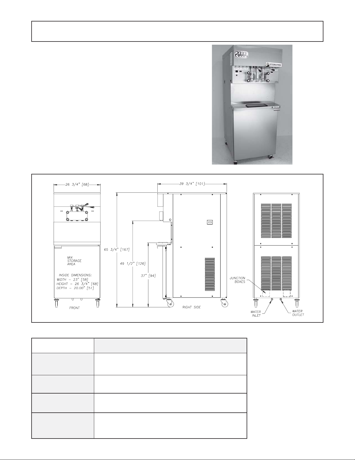
Figure 1. Model U431 Freezer
1.2 SPECIFICATIONS
SNOISNEMID
THGIEW
LACIRTCELE
GNILOOC
Figure 2. Specification
134ULEDOM
.etalpemanenihcamotrefeR
naretawTPN)mm5,21("2/1
1
"4/3-56:thgieH"4/3-93:htpeD"4/3-62:htdiW
etarC/w.SBL579.SBL529
.stiucricetarapesowT,hP3rohP1,tlov032/802
ecnaraelcdnuoralla"3s'qerdeloocriA.deloocriaroretaW
s'qerdeloocretaW.ecnaraelcpot"01dna
.sgnittifniardd
Page 10

2
Page 11
SECTION 2
INSTALLATION INSTRUCTIONS
2.1 SAFETY PRECAUTIONS
Do not attempt to operate the freezer until the safety precautions and operating instructions in the manual are read
completely and are thoroughly understood.
T ake notice of all warning labels on the freezer (Fig.3).The
labels have been put there to help you maintain a safe
working environment. The labels have been designed to
withstand washing and cleaning. All labels must remain
legible for the life of the freezer. Labels should be checked
periodically to be sure they have not been painted over,
rubbed off, fallen off, and can be recognized as warning
labels.
If you are in need of replacement labels, indicate the part
number, type of label, location of label, and quantity required along with your name and address and mail to:
Stoelting, LLC
Commercial Products
502 Hwy . 67
Kiel, WI 53042
3
Page 12
2.2 SHIPMENT AND TRANSIT
The freezer has been assembled, operated, and inspected
at the factory. Upon arrival at the final destination, the
freezer must be checked for any damage which may have
occurred during final transit.
With the method of packaging used, the equipment should
arrive in excellent condition. THE CARRIER IS RESPONSIBLE FOR ALL DAMAGE IN TRANSIT , WHETHER VISIBLE OR CONCEALED. Do not pay the freight bill until
the freezer has been checked for damage. Have the carrier note any visible damage on the freight bill. If concealed
damage and/or shortage is found later advise the carrier
within ten days and request inspection. The customer
must place claim for damage and/or shortages in shipment with the carrier. S toelting, Inc. cannot make any
claims against the carrier.
Figure 4. Water/Electrical Connections
E. Place the CLEAN-OFF-ON switches in the OFF
position before continuing. Figure 1 1.
2.3 FREEZER INST ALLATION
W ARNING
INSTALLATION MUST BE PERFORMED BY A
QUALIFIED ELECTRICIAN/REFRIGERATION SPECIALIST. INCORRECT INSTALLATION COULD
CAUSE PERSONAL INJURY, SEVERE DAMAGE
TO THE MACHINE AND WILL VOID THE WARRANTY.
Installation of the freezer involves moving the freezer close
to its permanent location, removing all crating, setting in
place, assembling parts, and cleaning.
A. Uncrate the freezer .
B. The freezer must be placed in a solid level position.
NOTE
Accurate leveling is necessary for correct drainage
of freezer barrel and to insure correct overrun.
C. The freezer must have a minimum of 3 inches (6
inches high ambient conditions) of space at all sides
and 10 inches at the top for proper circulation.
CAUTION
FAILURE T O PROVIDE ADEQUA TE VENTILA TION
WILL VOID WARRANTY!
D. Water-cooled freezers need an adequate water
supply . Install 1/2 inch pipe or 1/2 inch inside diameter copper water line to the freezer. Connect
water outlet to a drain using a 1/2 inch inside
diameter line. Automatic washer hoses work well for
final connections. All water connections must
comply with local codes. Figure 4.
2.4 INSTALLING PERMANENT WIRING
Permanent wiring is required by local codes, the following
procedure must be performed:
A. Refer to the nameplate at the rear of the freezer for
specific electrical requirements. Make sure the power
source in the building matches the freezer nameplate
requirements. Bring the wires into the junction boxes
through the access holes in the bottom rear of the
freezer. (Figure 4)
NOTE
Three phase freezers in areas of unbalanced electrical loads require special attention when connecting input electrical power. The unbalanced leg of
power (called wild or high) must be connected to L2
in the junction box.
B. Remove the lower back panel and the two junction
box covers located at the bottom of the freezer.
C. lnstall permanent wiring according to local code.
D. Check the auger shaft rotation by placing the MAIN
DRIVE switch in the CLEAN position. Auger shaft
rotation is clockwise as viewed through the clear plas-
tic front door. If the rot ation is not clockwise, turn
main electrical power OFF . Then reverse L1 and L3
electrical power lines to the junction box (three phase
only). Re-check auger shaft rotation. (Figure 5)
CAUTION
FLUSH ALL WA TER LINES BEFORE INST ALLATION. IN STORES WITH SEDIMENT IN W ATER,
ADD SUIT ABLE FILTER OR STRAINER TO WATER INLET .
Figure 5. Auger Rotation
4
Page 13
2.5 MIX PUMP (Serial #0 thru 17977)
A. Mix Pump Hose Installation
Follow the steps below to install the mix pump hose.
1. Turn pump on.
2. Feed one end of mix pump hose into the entering
or pick-up hose side (left) of black cover.
3. Gently push the hose into the black cover until it
begins to feed.
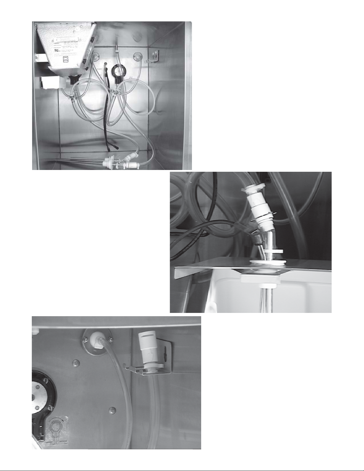
Figure 6. Mix Hose Installation
4. Allow the hose to feed itself thru the pump until
6" remains on the entering side.
5. Turn pump off.
6. Connect mix pump hose to pickup hose adapter
using small hose clamp.
CAUTION
DO NOT TWIST MIX PUMP HOSE.
7. Turn pump on.
8. Allow remaining 6" of tubing to feed thru pump
until hose adapter prevents further feeding.
9. Turn pump off.
10.Connect free end of mix pump hose to "4 way
Tee" as shown in Figure 7. When all connections
are complete the "4 way Tee" must be lower than
the black pump housing. Fig. 8
5
Page 14

B. Connect 1/2 inch I.D. plastic food grade
tubing to check valve and then to the mix container.
Observe check valve flow arrow. Secure with hose
clamps. Then place assembly thru hole in cover
and install retainer clip. Figure 9.
C. Connect 1/2 inch I.D. plastic food grade
tubing between the large port of air/mix tee and
refrigeratedmix transfer line. Secure with large
hose clamp or equivalent. Figure 9.
CAUTION
AIR/MIX TEE MUST REMAIN BELOW THE
BLACK COVER/CLAMP
. IF THE TEE IS ABOVE
THE PUMP MIX WILL DRAIN TO THE AIR COMPRESSOR RESUL TING IN PUMP DAMAGE.
D. Connect mix low cords. Figure 9.
/ 1177816
Figure 7. Mix Pump
6
Page 15
Refrigerated
ÅÅ
Å
ÅÅ
Mix Transfer
Line
4 Way Tee
Figure 8. 4 Way Tee
ÆÆ
Æ
ÆÆ
Large Port
ÅÅ
Å
ÅÅ
Air/Mix Tee
Low Mix Cord
Cover
ÈÈ
È
ÈÈ
ÌÌ
Ì
ÌÌ
ÇÇ
Ç
ÇÇ
Hose Holder
Figure 10. Hose Holder
ÉÉ
É
ÉÉ
Retainer
Mix
Clip
Container
Figure 9. Mix Inlet Tube & Probe Assy. Clip
7
Page 16
2.6 MIX PUMP (Serial #17978 and Up)
A. Mix Pump Hose Installation
Follow the steps below to install the mix pump hose.
1. Turn pump on.
2. Feed one end of mix pump hose into the entering
or pick-up hose side (left) of black cover.
3. Gently push the hose into the black cover until it
begins to feed.
6" (15cm)
Figure 11. Mix Hose Installation
4. Allow the hose to feed itself thru the pump
until 6" (15cm) remains on the entering side.
5. Turn pump off.
6. Connect mix pump hose to pickup hose
adapter using small hose clamp.
CAUTION
DO NOT TWIST MIX PUMP HOSE.
7. Turn pump on.
8. Allow remaining 6" (15cm) of tubing to feed thru pump
until hose adapter prevents further feeding.
9. Turn pump off.
10.Connect free end of mix pump hose to 3-way
Tee as shown in Figure 7. When all connections
are complete the 3- way Tee must be lower than
the black pump housing. Figure 8.
8
Page 17
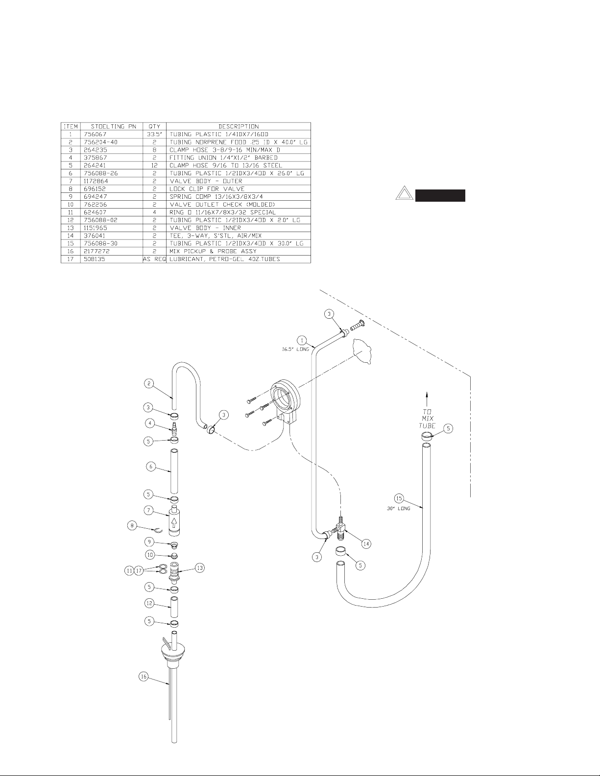
B. Connect 1/2 inch (12,7mm) I.D. plastic food grade
tubing to mix check valve (Item 7) and then to the
mix container. Observe check valve flow arrow.
Secure with hose clamps. Then place assembly
thru hole in cover and install retainer clip. See
Figure 9.
C. Connect 1/2 inch (12,7mm) I.D. plastic food grade
tubing between the large port of air/mix tee and
refrigerated mix transfer line. Secure with large
hose clamp or equivalent. See Figure 9.
CAUTION
AIR/MIX TEE MUST REMAIN BELOW THE
BLACK COVER/CLAMP. IF THE TEE IS
ABOVE THE PUMP MIX WILL DRAIN TO THE
AIR COMPRESSOR RESULTING IN PUMP
DAMAGE.
D. Connect mix low cords. Figure 9.
Figure 12. Mix Pump
9
Page 18
ÅÅ
Å
ÅÅ
Refrigerated
Mix Transfer
ÅÅ
Å
Large Port
(Air/Mix)
Figure 13. 3-way Tee
ÆÆ
Æ
ÆÆ
ÅÅ
Line
3-way Tee
ÇÇ
Ç
ÇÇ
Hose Holder
Low Mix Cord
ÌÌ
Ì
ÌÌ
Cover
ÈÈ
È
ÈÈ
ÉÉ
É
ÉÉ
Mix
Container
Figure 14. Mix Inlet Tube & Probe Assy. Clip
Retainer
Clip
Figure 15. Hose Holder
10
Page 19

SECTION 3
INITIAL SET-UP AND OPERATION
3.1 SAFETY PRECAUTIONS
SAFE OPERATION IS NO ACCIDENT; observe these
rules:
A. Know the freezer. Read and understand the operat-
ing instructions.
B. Notice all warning labels on the freezer.
C. Wear proper clothing. Avoid loose fitting garments,
and remove watches, rings or jewelry which could
cause a serious accident.
D. Maintain a clean work area. Avoid accidents by
cleaning the area and keeping it clean.
E. Stay alert at all times. Know which switch, push
button or control you are about to use and what
effect it is going to have.
F. Disconnect electrical power for maintenance.
Never attempt to repair or perform maintenance on
the freezer until the main electrical power has been
disconnected.
G. Do not operate under unsafe operating condi-
tions. Never operate this freezer if unusual or exces-
sive noise or vibration occurs.
3.2 OPERATING CONTROLS AND INDICA TORS
Before operating the freezer, it is required that the operator know the function of each operating control. Refer to
Figure 1 1 for the location of the operating controls on the
freezer.
A. Spigot Switch
When the spigot handle is opened the SPIGOT
switch will start the auger drive and refrigeration
systems. When the spigot handle is closed, the drive
B. Clean-Off-Serve Switch
The CLEAN-OFF-SERVE switch is a three position
toggle switch used to control the operation of the
refrigeration system and auger. When the switch is
placed in the CLEAN position, the refrigeration system will be off and auger will rotate for cleaning.
When the switch is placed in the OFF position, the
refrigeration system and auger will not operate.
When the switch is placed in the SERVE position,
the refrigeration system and auger will operate auto-
matically. The switch should be placed in the SERVE
position for normal operation.
C. Cabinet-Off-On Switch
The CABINET-OFF-ON switch is a two position
toggle switch. When the switch is placed in the OFF
position, the lower cabinet refrigeration system will
not run. When the switch is placed in the ON
position, the lower cabinet refrigeration system will
run until the preset temperature is reached; then
cycle ON and OFF to maintain that temperature.
Standby-
Serve
Low
Mix
Light
Clean-
Off-Serve
Cab
Off-On
Cab Indicator
Standby-
Serve
Low Mix
Light
Light
Freezing
Dispense Rate
Adjusters
Pump Switch
Figure 16. Operating Controls
WARNING
The CLEAN-OFF-SERVE switch must be placed
in the OFF position when disassembling for
cleaning or servicing. The freezer must be disconnected from electrical supply before removing any access panel.
Clean-
Off-Serve
D. Cab Indicator Light
A flashing light indicates the cab OFF-ON switch is
in the OFF position, no refrigeration. Place the OFFON switch in the ON position for cab refrigeration.
E. Pump Switch
The pump motor switch is a two position toggle
switch. When the switch is placed in the OFF
position, the pump will not run. When the switch is
placed in the ON position, the pump will run until the
preset pressure is reached, then cycle ON and OFF
as product is drawn to maintain that pressure.
F. Standby/Serve Switch
The standby/serve switch is a two position toggle
switch. When the switch is placed in the Standby
position the freezer will cycle to maintain a
temperature below 41°F. When the switch is in the
Serve position the freezer will cycle to maintain a
servable product.
G. Freezing Switch
The freezing switch is a two position toggle switch.
When the switch is placed in the ON position
the freezer will be forced to run 30 seconds after the
temperature control is satisfied.
11
Page 20

H. Dispense Rate Adjusters
The dispense rate adjuster limits the opening of the
spigot. To adjust product dispense rate, turn the
adjusting knob clockwise for slower flow and counterclockwise for faster flow.
I. High Head Pressure Cut Out
If the head pressure exceeds 445 PSIG (28 bar) air
cooled andwater cooled, the high head pressure
cutout will trip. The reset button can be accessed
from the side of thefreezer.
J. Low Mix Light
The low mix light will illuminate when the liquid level
in the mix container drops below two gallons.
K. Front Door Safety Switch
The front door safety switch prevents the auger from
turning when the front door is removed. The switch
is open when the door is removed and closed when
the door is properly installed.
12
Page 21

3.3 IMPORTANT INFORMATION REGARDING
CLEANING AND SANITIZING
Soft serve and shake freezers require special
consideration when it comes to food safety and
proper cleaning and sanitizing.
The following information specifically covers issues
for cleaning and sanitizing frozen dessert freezers.
This information is meant to supplement a
comprehensive food safety program.
Soil Materials Associated with Frozen Dessert
Machines
CLEANING
· Is the removal of soil materials from a surface.
· Is a prerequisite for effective sanitizing.
NOTE
An UNCLEAN surface will harbor bacteria that can
defy sanitizing efforts.
Bacteria can develop and resist sanitizing efforts
within a layer of soil material (milkstone). Thorough
cleaning procedures that involve milkstone
removal are critical for operators of frozen
dessert machines.
MILKFAT/BUTTERFAT – As components of icecream/frozen custard mix, these soils will
accumulate on the interior surfaces of the machine
and its parts. Fats are difficult to remove and help
attribute to milkstone build-up.
MILKSTONE – Is a white/gray film that forms on
equipment and utensils that come in contact with
dairy products. These films will accumulate slowly
on surfaces because of ineffective cleaning, use of
hard water, or both. Milkstone is usually a porous
deposit, which will harbor microbial
contaminants and eventually defy sanitizing
efforts.
Once milkstone has formed, it is very difficult to
remove. Without using the correct product and
procedure, it is nearly impossible to remove a thick
layer of milkstone.
(NOTE: general-purpose cleaners DO NOT remove
milkstone.) This can lead to high bacteria counts
and a food safety dilemma.
IT IS BEST TO CONTROL MILKSTONE ON A
DAILY BASIS BEFORE IT CAN BECOME A
SIGNIFICANT FOOD SAFETY PROBLEM.
In addition to food safety, milkstone can cause
premature wear to machine parts which can add to
costs for replacement parts or possibly more
expensive repairs if worn machine parts are not
replaced once they have become excessively worn.
Important Differences Between Cleaning and
Sanitizing
CLEANING vs. SANITIZING
It is important to distinguish between cleaning and
sanitizing. Although these terms may sound
synonymous, they are not. BOTH are required for
adequate food safety and proper machine
maintenance.
SANITIZING
· Kills bacteria.
· Can be effective on clean surfaces only.
· DOES NOT clean or remove milkstone.
NOTE
Using a SANTITIZER on an unclean surface
will not guarantee a clean and safe frozen
dessert machine.
Proper Daily Maintenance:
The Only Way to Assure Food Safety and
Product Quality
Proper daily maintenance can involve a wide variety
of products and procedures. Overall, the products
and procedures fall into three separate categories.
(Please note that this is a brief overview intended for
informational purposes only.)
1. CLEANING – This involves draining mix from the
freezer barrel and rinsing the machine with
water. Next, a cleaner is run through the
machine. Then, the machine is disassembled
and removable parts are taken to the sink for
cleaning.
2. MILKSTONE REMOVAL – Since almost all
cleaners do not have the ability to remove
milkstone, the use of a delimer becomes
necessary. Although this procedure may not be
needed on a daily basis, it will usually follow the
cleaning procedure. It requires letting a delimer
solution soak in the machine for an extended
period of time. Individual parts are also soaked
in a deliming solution for an extended period of
time (more about delimers in Additional
Information).
3. SANITIZING – After the machine has been
cleaned and contains no milkstone, the
machine is reassembled. Then a FDA-approved
sanitizing solution is run through the machine to
kill bacteria. The machine is then ready for food
preparation.
13
Page 22
As a recommended cleaner and sanitizer for your
frozen dessert machine, STERA-SHEEN has proven
to be one of the best daily maintenance products for:
· CLEANING – Thorough removal of all solids
including butterfat and milk fat.
The ideal concentration of chlorine needs to be 100
ppm (as stated by the FDA).
NOTE
Follow the directions on the container for proper
concentration.
· MILKSTONE REMOVAL – Complete removal of
milkstone.
· SANITIZING – FDA-approved no rinse sanitizer
for food contact surfaces.
Additional Information
THE USE OF DELIMERS
A delimer is a strong acid that has the ability to
dissolve milkstone. This type of chemical may
become necessary once high levels of milkstone
have developed. While these products are very
effective for removing HIGH levels of milkstone, they
are not ideal for two reasons:
1. PRODUCT SAFETY – Strong acids are
dangerous chemicals and handling them
requires safety
2. MACHINE DAMAGE – Strong acids will attack
metal and rubber causing premature wear of
parts. The use of a delimer needs to be closely
monitored to avoid damage to machine surfaces
and parts.
There are two main factors that contribute to falling
chlorine concentrations in a sanitizing solution.
1. PRODUCT USE – As the chlorine in the
solution is being used, chlorine concentrations
fall.
2. TIME – As time passes, small amounts of
chlorine “evaporate” from the solution. (That is
why you can smell it.)
Sanitizing solutions should not be allowed to fall
below 100 ppm chlorine. New solutions should be
mixed once old solutions become ineffective.
3.4 DISASSEMBL Y OF FREEZER P ARTS
WARNING
Moving machinery can grab, mangle and dismember. Place the CLEAN-OFF-SERVE toggle
switch in the OFF position before disassembling
for cleaning or servicing. Placing the CLEAN-OFFSERVE toggle switch in the SERVE position during cleaning or servicing may result in serious
personal injury.
With proper daily use of STERA-SHEEN or it’s
equivalent, there is no need for the use of a
DELIMER.
DO NOT USE BLEACH
· BLEACH HAS ABSOLUTELY NO CLEANING
PROPERTIES.
· BLEACH IS CORROSIVE. It can and will
damage components of the machine causing
premature wear and metal corrosion.
GENERAL PURPOSE CLEANERS
General purpose cleaners do not have the ability to
remove milkstone. Milkstone will become a problem
if not remedied with additional products and
procedures.
THE USE OF CHLORINE TEST STRIPS
“Test strips” are used to determine concentrations of
active chlorine in sanitizing solutions. To use the
strips, tear off a small portion and submerge it into
the sanitizing solution. Then, compare the color
change to the color key on the side of the test strip
dispenser to determine the approximate chlorine
concentration.
Before using the freezer for the first time, complete freezer
disassembly, cleaning and sanitizing procedures will need
to be followed. Routine cleaning intervals and procedures
must comply with the local and state health codes.
Inspection for worn or broken parts should be made at
every disassembly of the freezer for cleaning or other
purposes. All worn or broken parts should be replaced to
ensure safety to both the operator and the customer and
to maintain good freezer performance and a quality product. Two normal wear areas are the auger flights and front
auger support bushing (see Figure 12).
T o disassemble the freezer , refer to the following steps:
Wear Line
ÈÈ
È
ÈÈ
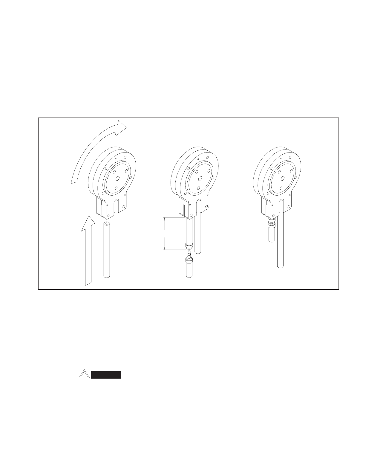
Figure 17. Auger Flight Wear & Front Auger
Support Bushing Wear
14
Page 23
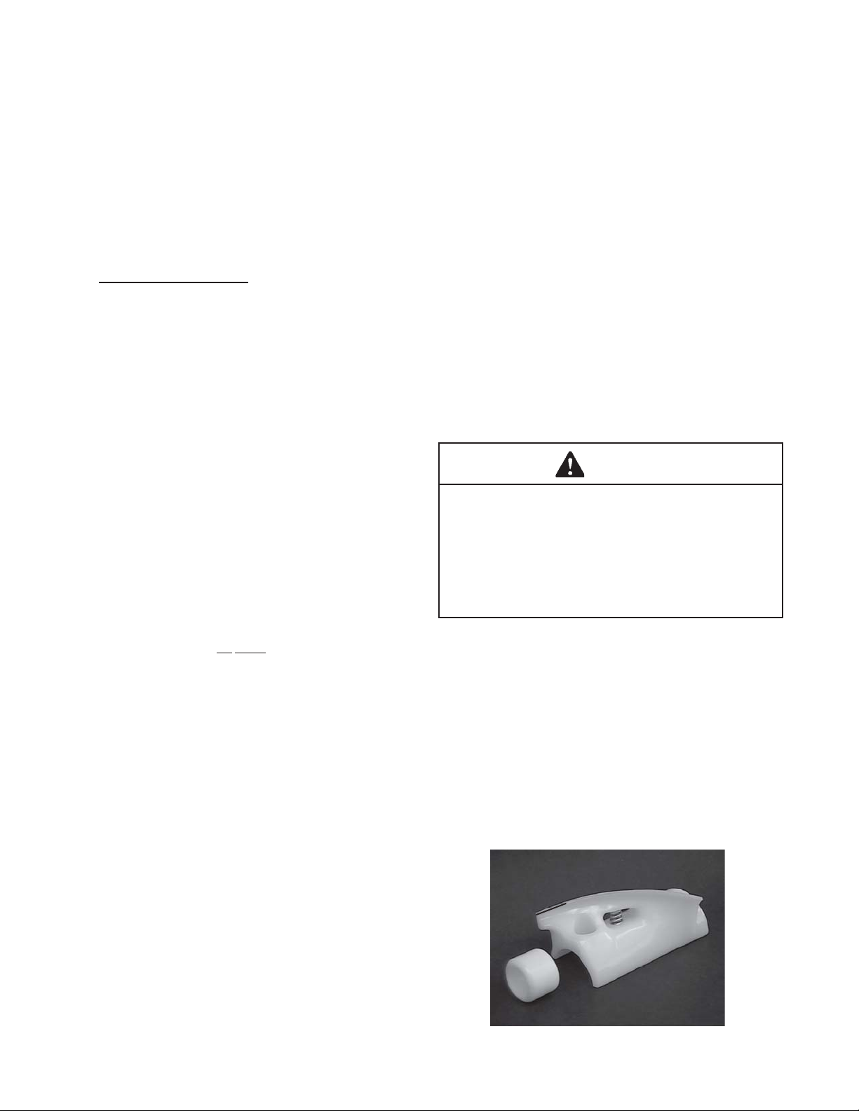
A. Disassembly Of Front Door
1. Remove the front door by turning off the circular
knobs and then pulling the front door off the studs.
2. Remove the air bleed valve by unscrewing the knob
while holding the valve stem from behind. Remove
the compression spring and push air bleed valve
through the rear of the front door.
3. Remove the spigot through the bottom of the front
door (see Figure 13). Remove all O-rings from
spigots and air bleed valve.
Figure 18. Front Door Disassembly
B. Disassembly Of Auger
1. Remove the front auger support by pulling it
straight out of the freezer barrel.
2. Remove the plastic bearing from the front auger
support.
Figure 20. Rear Seal Removal
3.5 CLEANING DISASSEMBLED PARTS
Disassembled freezer parts require complete cleaning,
sanitizing and air drying before assembling. Local and
state health codes will dictate the procedure required.
Some state health codes require a four sink process (prewash, wash, rinse, sanitize, air dry), while others require
a three sink process (without the pre-wash step). The
following procedures are a general guideline only. Consult
your local and state health codes for procedures required
in your location.
A. To clean the freezer parts, disassemble all parts.
(Refer to section 3.4 for the disassembly of freezer
parts.)
B. Place all front door and auger parts in clean 90° to
110°F (32°C to 43°C) water and wash thoroughly
(four sink procedure only).
C. Place all parts in 90° to 110°F (32°C to 43°C) , mild
detergent water and wash thoroughly.
3. Remove the auger by pulling slowly and rotating
out of the freezer barrel. As the auger is
withdrawn, remove each plastic flight and spring
from the auger . Be careful not to scratch inside of
freezer barrel when removing flights or auger.
Remove the spring from each auger flight.
Figure 19. Auger Flight Removal
4. Keep the rear of the auger tipped up once it is
clear of the freezer barrel.
5. Wipe spline lubricant off hex end of auger with a
paper towel. Remove the rear seal. Figure 15.
D. Rinse all parts with clean 90° to 110°F (32°C to
43°C) water.
F. Sanitize all freezer parts following procedures out
lined below.
3.6 SANITIZE FREEZER PARTS
A. Use a sanitizer mixed according to manufacturer's
instructions to provide a 100 parts per million strength
solution. Mix sanitizer in quantities of no less than 2
gallons of 90° to 110°F (32°C to 43°C) water. Allow
the sanitizer to contact the surfaces to be sanitized
for 5 minutes. Any sanitizer must be used only in
accordance with the manufacturer's instructions.
B. Place all parts in the sanitizing solution for 5 minutes,
then remove and let air dry completely before assem
bling in freezer.
15
Page 24
3.7 CLEANING THE FREEZER
CAUTION
Risk of Product Damage
Do not use acid cleaners, strong caustic compounds
or abrasive materials to clean any part of the freezer
exterior or plastic parts.
The exterior should be kept clean at all times to
preserve the lustre of the stainless steel. A good
grade of stainless steel has been used on the
freezer to ease clean-up. To remove spilled or dried
mix, simply wash the exterior in 90° to 110°F (32°C
to 43°C) , soapy water and wipe dry.
É
ÉÉ
ÉÉ
Lubricate
with
Socket
ÊÊ
Ê
ÊÊ
ÉÉ
É
ÉÉ
ÉÉ
É
ÉÉ
Lubricate with Petrogel
Figure 21. Rear Seal Lubrciation
C. Lubricate the hex drive end of auger with a small
amount of white socket lubricant. A small container
of socket lubricant is shipped with the freezer.
Lubricant
Do not use highly abrasive materials as they will
mar the finish. A mild alkaline cleaner is recommended. Use a soft cloth or sponge to apply the
cleaner. For best results, wipe in the direction of the
grain of the steel.
A. Clean the rear seal surface from inside of the freezer
barrel.
B. Using this sanitizing solution and the large barrel
brush provided, sanitize the barrel by dipping the
brush in the sanitizing solution and brushing the
inside of the barrel.
C. Remove the rear drip tray by pulling from side panel.
Clean and replace drip tray.
3.8 ASSEMBLING FREEZER
To assemble the freezer parts, refer to the following steps:
NOTICE
Petro-Gel sanitary lubricant or equivalent must be
used when lubrication of freezer parts is specified.
NOTICE
The United States Department of Agriculture and
the Food and Drug Administration require that lubricants used on food processing equipment be certified for this use. Use Lubricants only in accordance
with the manufacturer's instructions.
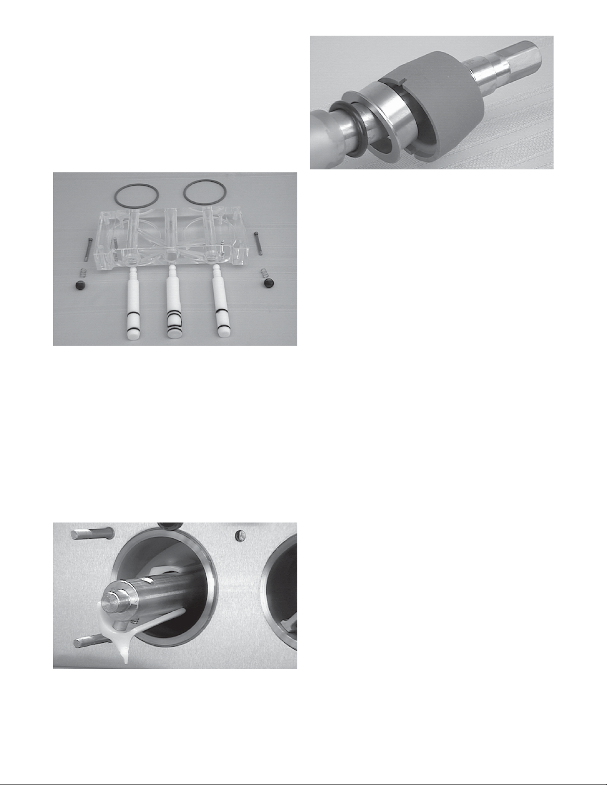
A. Assemble all O-rings onto parts dry, without lubri-
cation. Then apply a thin film of sanitary lubrication
to exposed surfaces of the O-rings.
B. Lubricate rear seal area on auger shaft with a thin
layer of sanitary lubricant. Install the rear seal O-ring.
Lubricate outside of rear seal O-ring with sanitary
lubricant.
C. Install stainless steel rear seal adapter into rear seal
dry (without lubricant). Lubricate inside surface of
rear seal adapter and install onto auger shaft. DO
NOT lubricate outside of rear auger seal (see Figure
16).
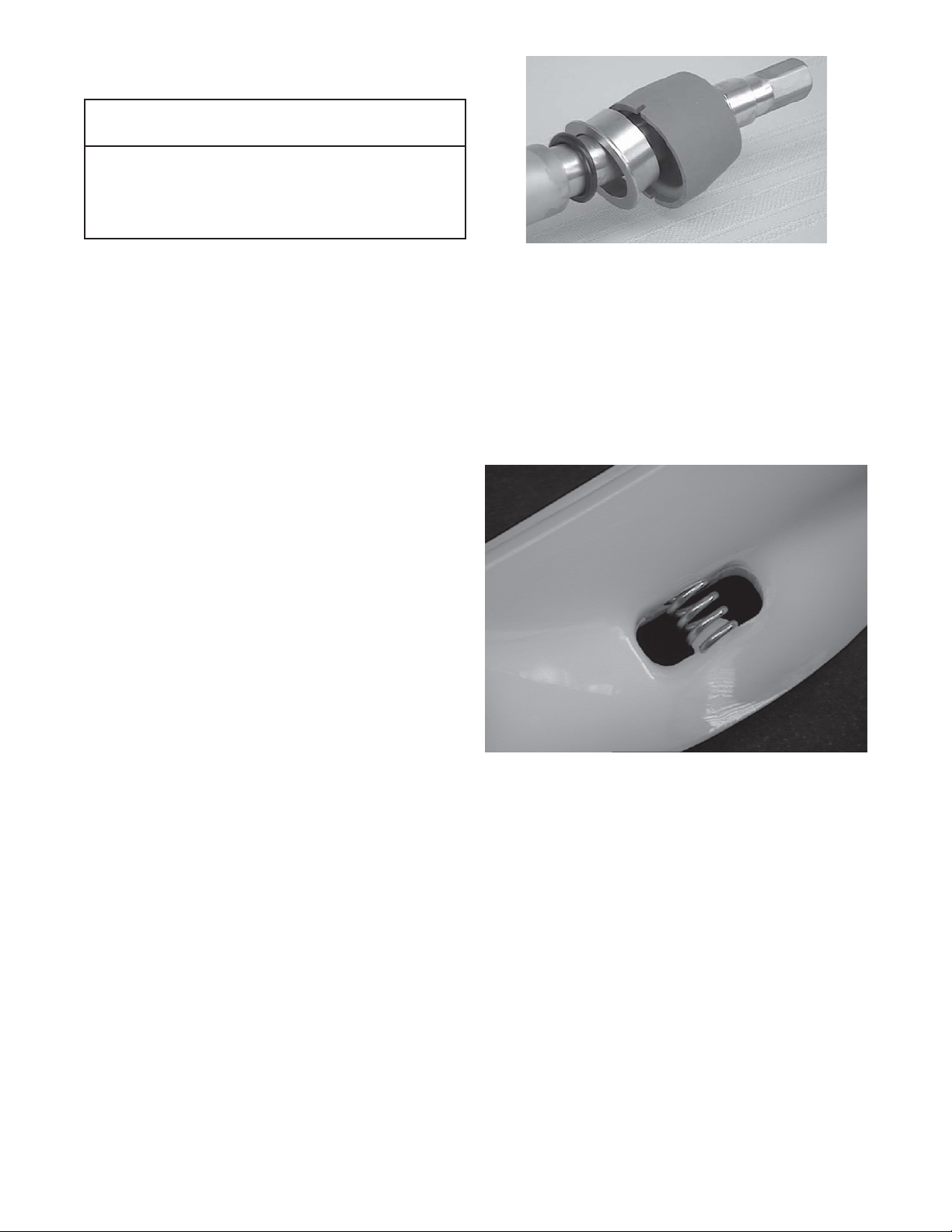
D. Screw the springs onto the studs in plastic flights.
Spring must be screwed into the flights completely to provide proper tension (see Figure 17).
Figure 22. Spring Installation
E. Install first flights to bottom of auger, rotate, add
successive flights from bottom as the auger is pushed
slowly into the freezer barrel. Carefully engage auger
with drive socket in speed reducer by rotating auger
slowly and pushing on end of auger.
F. Apply a thin film of sanitary lubricant to the inside and
outside of the front auger support bearing, then place
on the front of the auger. Assemble the front auger
support onto the auger bearing.
NOTICE
Position the front support on auger so legs do not
interfere with the pin on the back of the front door
assembly. Front door must push auger in slightly
when it is being tightened to prevent the rear seal
from leaking.
16
Page 25
G. Assemble O-rings onto the spigot dry, without
lubrication. Then apply a thin film of sanitary lubricant
to the outside of the O-rings and spigot bodies.
H. Install the spigots through the bottom of the front
door ( see Figure 18).
Figure 23. Front Door Assembly
I. Assemble the air bleed valve O-ring onto the air
bleed valves. Position the O-ring in groove close to
the wide part. Apply a thin film of sanitary lubricant to
the O-rings.
J. Insert the air bleed valves from the back of the front
door. Install compression springs onto air bleed
valves, then screw knobs on finger tight.
K. Apply a thin film of sanitary lubricant to the door seal
O-rings, and fit into the grooves on the rear of the
front door.
L. Place the front door assembly on the mounting studs
and push front door against the freezer carefully.
M. Secure front door assembly by placing the knobs on
the studs and alternately tighten opposite corners
until finger tight only. Do not overtighten. Proper
O-ring seal can be observed through the transparent
front door.
N. Move the spigot handles to the closed position.
17
Page 26
3.9 SANITIZING
Sanitizing must be done after the freezer is clean and just
before the freezer is filled with mix. Sanitizing the night
before is not effective. However, you should always clean
the freezer and parts after using it.
WARNING
The United States Department of Agriculture and
the Food and Drug Administration require that
all cleaning and sanitizing solutions used with
food processing equipment be certified for this
use.
When sanitizing the freezer, refer to local sanitary regulations for applicable codes and recommended sanitizing
products and procedures. The frequency of sanitizing must
comply with local health regulations. Mix sanitizer according to manufacturer’s instructions to provide a 100
parts per million strength solution. Mix sanitizer in quantities of no less than 2 gallons of 90°F to 110°F 90° to
1 10°F (32°C to 43°C) water. Allow sanitizer to contact the
surfaces to be sanitized for 5 minutes. Any sanitizer must
be used only in accordance with the manufacturer’s instructions.
C. Let sanitizing solution fill the freezer barrel to air bleed
valve, then close the valve by pulling out to lock in
place.
D. Place the CLEAN-OFF-SERVE toggle switch in
the CLEAN position.
Figure 25. Draining Sanitizer
E. Check for leaks when the freezer barrel is first
pressurized with sanitizing solution.
1. Check for leaks at the plastic front door, the
O-rings may not be sealed.
Air Bleed Valves
Figure 24. Air Bleed Valves
CAUTION
Risk of Product Damage
Avoid prolonged contact of sanitizer with freezer parts.
Prolonged contact of sanitizer with freezer may cause
corrosion of stainless steel parts.
2. Check the drain located at the center of the
Drip Tray for leaks coming from the rear of the
Rear Auger Seal.
3. Check inside cab unit for leaks at hose connections.
F. Using a sanitized soft bristle brush or equivalent,
dipped in sanitizing solution, clean mix container .
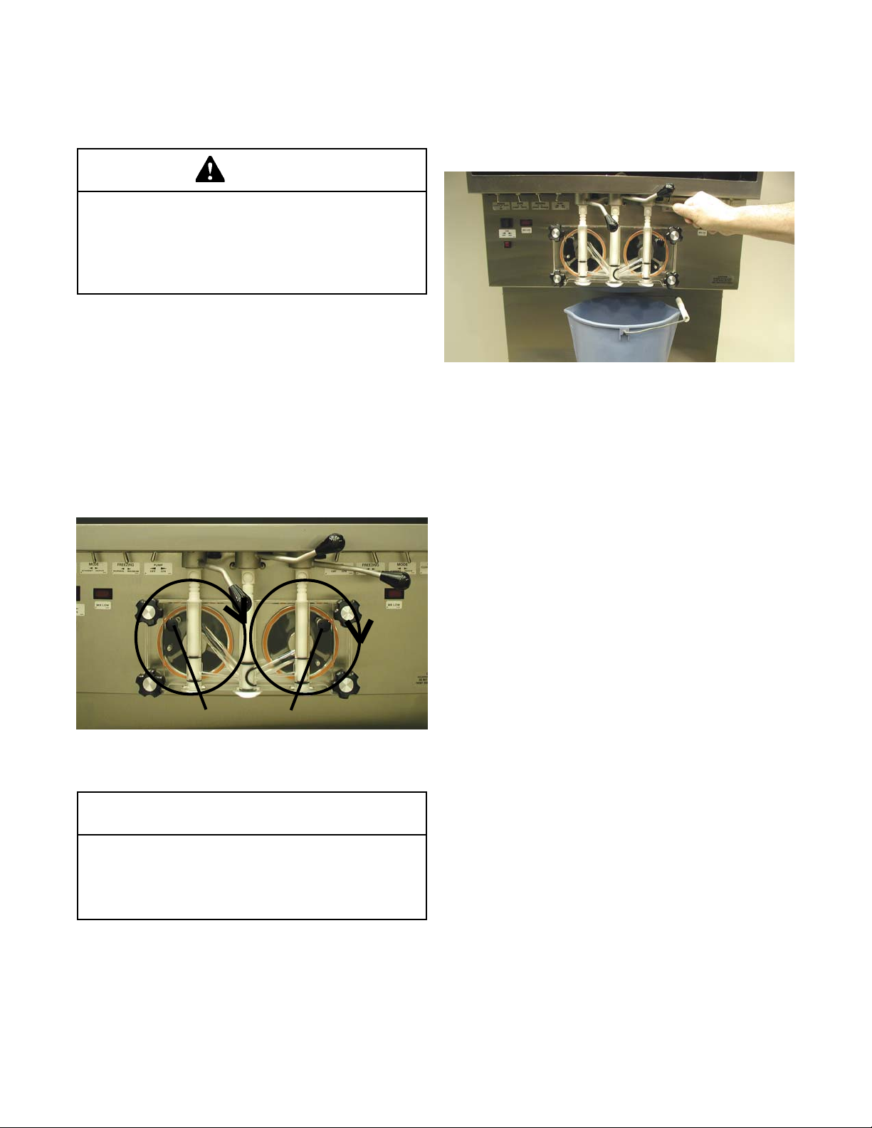
G. After five minutes, open spigot to expel sanitizing
solution. Drain all solution from freezer using all three
spigots (See Figure 20).
H. Close the spigot and place the mix pump switch
and the CLEAN-OFF-SERVE switch in the OFF
position.
The freezer is now sanitized and ready for adding mix.
3.10 INITIAL FREEZE DOWN AND OPERA TION
This section covers the recommended operating procedures to be followed for the safe operation of the freezer.
A. Sanitize just prior to use according to instructions
outlined in this manual.
A. Prepare 3 gallons of sanitizing solution following
manufacturer's instructions, and pour into storage
container .
B. Place the mix pump switch in the ON position and
open air bleed valve on the front door by pushing
valve in and holding (see Figure 19).
B. Prepare the desired amount of mix and then fill each
storage container with approximately 3 gallons or
more of mix. Place a container(s) of mix in the refrigerated cabinet. If drawing from a storage container ,
place the draw tube through the cover to the bottom
of the container . If drawing from a bag in a box, remove the cap, push out all of the air, and insert the
adaptor.
18
Page 27

Mix Low
Sensor
Figure 26. Refrigerated Cabinet
C. Place the mix pump switch in the ON position. Im
mediately open the spigot and let approximately 8
ounces of liquid mix with sanitizing solution drain
out of the spigot.
The freezer is designed to dispense the product at a
reasonable draw rate. If the freezer is overdrawn, the
result will be a soft product and air pops. If this should
occur, allow the freezer to run for approximately 30
seconds before dispensing additional product. After a
while the operator will sense or feel when the freezer is
beginning to fall behind, and will slow down on the rate
of draw so as not to exceed the freezer's capacity .
Do not operate the freezer when the MIX LOW light is
on or with less than 1-3/4" (4.4 cm) of mix in the
mix container. Refill the mix cont ainer immediately.
D. Close the spigot and open the air bleed valve on the
front door by pushing the valve in and holding. Allow
the barrel to fill until the mix level is 1/2" (2.7 cm)
below air bleed valve, then release valve and pull
closed to lock in place.
E. Start the compressor and drive by placing the
CLEAN-OFF-SERVE switch in the SERVE position
F . The product will be ready to serve after the compres-
sor and drive have cycled off, or in approximately
12 minutes.
G. The refrigeration is automatically actuated when
the spigot is opened. For normal dispensing, open
the spigot no more then 90°. (This is when the
handle knob is pointed directly away from the front
door.). This position provides excellent control over
the product and aids in making desired shaped
portions. Spigot Rate Adjusters are located under
the Header Panel, to the immediate right of each
Spigot Handle. Turning the S pigot Rate Adjuster
clockwise will increase the dispense rate.
(see Figure 22)
Spigot Rate Adjusters
Figure 27. Dispensing Product
3.11 MIX INFORMATION
Mix can vary considerably from one manufacturer to
another. Differences in the amount of butter-fat content and
quantity and quality of other ingredients have a direct
bearing on the finished frozen product. A change in freezer
performance that cannot be explained by a technical
problem may be related to the mix.
Proper product serving temperature varies from one
manufacturer's mix to another. Mixes should provide a
satisfactory product in the 17° to 20°F (-7° to -6°C) range.
Diet and low-carb mixes typically freeze to proper consistency at higher temperatures.
When checking the temperature, stir the thermometer in
the frozen product to read the true temperature.
Mix does not improve with age. Old mix, or mix that has
been stored at too high a temperature, can result in a
finished product that is less than satisfactory from the
appearance and taste standpoint. To retard bacteria growth
in dairy based mixes, the best storage temperature range
is between 36° to 40°F (2.2° to 4.4° C).
19
Page 28

3.12 OPERATION OF MIX PUMP
The pump switch is located on the front of the freezer.
When the pump switch is placed in the ON position, the mix
pump motor will be actuated to pump mix into the freezer
cylinder. When the set pressure is reached, the mix pump
will shut off automatically. When the switch is placed in the
OFF position, the mix pump will be inoperative.
C. The over-run adjustment is preset at the factory. If an
adjustment becomes necessary, refer to Section 4.
NOTICE
Any cleaning procedure must always be followed
by sanitizing before filling freezer with mix. (Refer to
section 3.3)
NOTE
The mix pump motor is equipped with an internal
overload that will “trip”, disabling the pump when the
motor is overloaded. Consult the trouble shooting
section for corrective information.The internal overload will automatically reset after cooling. If the condition continues, contact a qualified service person.
CAUTION
Risk of Product Damage
Mix pump hose must be repositioned every 1 -2 weeks
or 60 hours of operation. Failure to comply will result
in reduced mix pump liquid capacity , dispense stoppage, popping, and possible mix pump hose leakage. Hose leakage may damage the pump roller assembly and void the factory warranty .
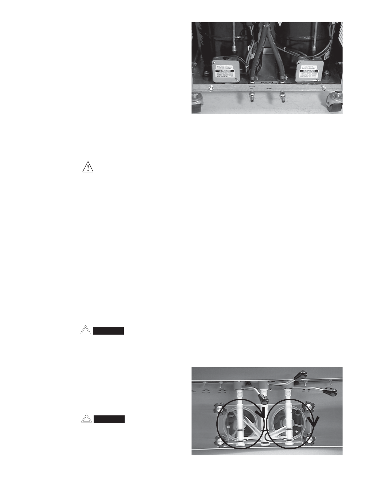
A. Mix Operation: The peristaltic mix pump contains
one continuous mix pump hose. When looking at the
face of the peristaltic mix pump, the left side of the
hose is the suction or pickup. The right side of the
hose is the discharge. Mix is drawn up the suction
side of the hose and transferred thru the discharge
side to the freezer (see Figure 23).
B. Air Operation: The air compressor operates whenever
the peristaltic mix pump is running. Air enters thru a
check valve on the piston downstroke. The air is
discharged thru a second check valve, on the piston
upstroke. The air and mix join at the tee and then
travel to the freezer.
3.13 MIX PUMP CLEANING
The mix pump is approved for CIP (clean in place) and is
thoroughly cleaned as cleaning solutions are pumped thru
the freezer. We recommend completely disassembling
the pump and connecting tubing every 14 days for inspection
of parts to confirm the CIP has been properly performed. If
any residue is detected clean or replace those parts as
outlined below.
1. Place CLEAN-OFF-SERVE switch in CLEAN position. Allow the auger to agitate for 5 to 10 minutes.
2. Remove suction tube from mix container. Draw off the
mix remaining in freezer barrel.
3. Pump 2 gallons (7.5 liters) of cold potable water thru
freezer until water at spigot is free of mix.
4. Pump 2 gallons (7.5 liters) of 90° to 110°F (32°C to
43°C) detergent solution water thru freezer. The use
of soft water is recommended, along with dishwashing
detergents such as “Joy ,” “Dawn,” or equivalent.
5. Place mix pump switch in OFF position. Open spigot
to relieve remaining pressure.
6. Place CLEAN-OFF-SERVE switch in OFF position.
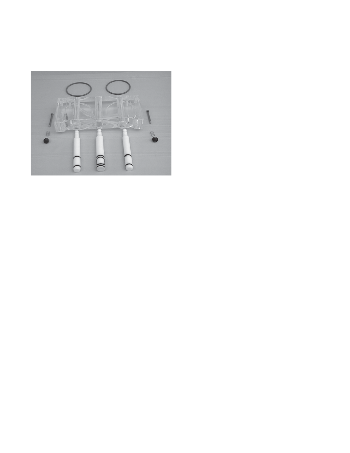
3.14 DISASSEMBLY AND INSPECTION OF
REMOVABLE PARTS
Inspection of removable parts should be made whenever
maintenance is performed or pump requires disassembly.
Mix
Intake
ÆÆ
Æ
ÆÆ
Figure 28. Mix Pumps
Mix
Discharge
ÆÆ
Æ
ÆÆ
ÆÆ
Æ
ÆÆ
3-way Tee
ÆÆ
ÆÆ
Æ
Hose
Holder
WARNING
Hazardous Moving Parts
Revolving pump head can grab, mangle, and cause
serious crushing injury. The Power switch must be
placed in the OFF position for cleaning and power
must be disconnected when disassembling or
servicing.
CAUTION
System Under Pressure
Never disconnect hoses from freezer or pump without
first opening spigot to relieve pressure.
20
Page 29

NOTE
If the mix lines or air line is difficult to remove, soften
with a rag soaked in hot water. Hose connections
may be sprayed with Haynes Sanitary Lubricant for
ease of removal. Do not loosen or remove the mix
pump cover wingnuts. Maintain the mix pump hose
in its operational condition.
1. Loosen clamp and remove air hose from pump
compressor.
2. Loosen clamp and disconnect mix pump hose.
Remove the pickup hose, mix check valve and pickup
hose adapter (and bag adapter if applicable) as an
assembly from mix container.
3. Completely disassemble both hose assemblies and
check valve. Place hoses, tee, check valve assembly , and pickup hose adapter in 90° to 1 10°F (32°C to
43°C), mild detergent water and wash thoroughly . Use
soft bristle brushes to clean inside of fittings. Rinse
all parts in clean 90° to 1 10°F (32°C to 43°C) water
(see Figure 24).
4. Carefully inspect each part for wear or damage.
Replace worn or damaged parts.
9. Sanitize assembled freezer as per instructions
outlined in Section 3.9).
Figure 30. Cleaning Air Tube
5. Wash feed tube and air tube with 90° to 1 10°F detergent water and brushes provided. Rinse with clean,
90° to 1 10°F water (See Figure 25 and 26).
6. Prepare two gallons (7.5 liters) of sanitizing solution
using a USDA certified grade sanitizing solution.
Sanitize all removed parts, then air dry .
7. Check Hose Service Record decal to determine if
hose
reposition or replacement is required at this
time.
8. Reassemble both hose assemblies per the diagram
located on the inside of the cab door. Reconnect
assemblies to the pump and discharge hose, using
the clamps. (See Figure 27 or refer to Section 2.5 Mix
Pump).
Figure 31. Cleaning Feed Tube
Pump
Compressor
Figure 29. Removable Parts Figure 32. Mix Pump Tube Routing
21
Page 30

22
Page 31

SECTION 4
MAINTENANCE INSTRUCTIONS
4.1 FREEZER ADJUSTMENT
This section is intended to provide maintenance personnel with a general understanding of the freezer adjustments. It is recommended that any adjustments in this
section be made by a qualified person.
4.2 PRODUCT TEMPERATURE ADJUSTMENT
A potentiometer is used to control the product temperature.
NOTE
Proper assembly of freezer, worn p arts, leaks, proper
"prime" level, clean condenser, worn drive belt s all
attribute to product temperature. Be sure your machine is properly maintained before adjusting temperature, you may be masking another problem.
To change the temperature of the product, follow the steps
below:
A. Loosen the two screws under the header display
sign, then pull sign out and down.
B. Use a screw driver to make desired adjustment. A
label near the potentiometer will give complete instructions. Figure 26.
The mix pump has been preset at the factory to produce a
product with approximately 40% overrun. Because of
differences in mix formulation, temperatures and barometric pressure, this figure may vary. It will be necessary
for approximately 2 gallons of mix to be pumped thru the
freezer before changes in the product are noticeable due
to adjustments in overrun.
Overrun is controlled by the length of the air compressor
piston stroke within the piston cylinder. Lengthening the
stroke within the cylinder will increase overrun. Conversely, shortening the stroke will decrease overrun. To
perform an overrun adjustment, refer to the following
procedure:
A. Turn the mix pump switch to the OFF position.
Disconnect power sources/circuit breakers.
B. Remove the lower back panel from freezer.
C.
On air compressor side of pump, locate the long/
slender piston rocking arm. The rocking arm down-
ward travel is limited by a stationery cam. On the face
of the cam there is an overrun setting indicator plate
numbered 3 thru 8 and an adjustment knob.
Figure 27.
Figure 33. Potentiometer
4.3 OVERRUN ADJUSTMENT
The product when served is a combination of air and mix.
Overrun is a measure of the amount of air blended into the
mix.
Overrun can be expressed in terms of the amount of
weight loss for a given volume. For example, if a pint of
liquid mix weighs 18 ounces and a pint of frozen product
with air added weighs 12 ounces, the overrun is said to be
50 percent (18 oz. - 12 oz. = 6 oz., (6/12) x 100 = 50%.
The overrun can be checked by placing a one pint
container on an ice cream scale and zeroing out the scale.
Then fill a one pint container with frozen product. The
container should be filled over the top and leveled with a
straightedge. The product should not contain any air
pockets. When weighed on an ice cream scale, one pint
of product should weigh 12 to 13 ounces.
ÊÊ
Ê
Overrun Adjustment
Figure 34. Overrun Adjustment
D.The overrun setting is indicated by a pointed pin.
E. T o adjust overrun, loosen the allenhead screw
(located within the center of the adjustment knob)
with the 5/32" allen wrench provided. Rotate the
adjustment knob counterclockwise to a higher
number for higher overrun, or clockwise to a lower
number for lower overrun. Each number multiplied by
10 represents the overrun percentage (ie: #4 = 40%
overrun).
23
ÊÊ
Page 32

F. Tighten the allen screw, then place the wrench back
R
p
in its clip. Replace the lower back panel and secure
with the four screws. Turn the mix pump power switch
to the ON position.
CAUTION
NEVER DISCONNECT HOSES FROM FREEZER
OR PUMP WITHOUT FIRST OPENING SPIGOT
TO RELIEVE PRESSURE.
4.4. MIX PUMP HOSE REPOSITION (every one or
two weeks.)
NOTE
Mix pump hose must be repositioned every 1 - 2
weeks. Failure to comply will result in reduced mix
pump liquid capacity , dispense stoppage, popping,
and possible mix pump hose leakage.
Find a system that works for you. Operating until
hose breaks shortens pump life, causes downtime
and increases cleaning costs. Hours of (pump)
operation approx. 60, Gallons of (material), Time
frame = Bi-Weekly.
1. Run cleaning solution through pump.
2. Turn pump of f and relieve any pressure by
opening the spigot.
3. Grasp the pick-up hose end of the mix pump
hose with one hand and turn the pump on. Pull
down on the pick-up hose end until 12 to 14
inches of tubing has reversed fed through the
pump, then turn the pump off.
3. Disconnect mix pump hose at each end.
4. Grasp the discharge hose end with one hand
and turn the pump on. Pull down on the hose
until all of the remaining hose is removed from
the pump.
5. Turn pump roller assembly so one roller is at
6:00.
oller
Roller
Cover/Clam
Cover/Clamp
Inlet
Side
Inlet
Side
Discharge Side
Discharge
Side
4. Loosen small clamp at the pick-up hose
adapter and (viewed from back) disconnect
Figure 35. Pump Roller Assembly
mix pump hose.
5. Cut 7-1/2 inches off the end of the mix pump
hose.
6. Reconnect mix pump hose to adapter .
7. Continue normal operation. Mix hose will
automatically reposition itself with adapter near
black cover .
NOTE
Each hose is long enough for 3 repositions before
replacement is required. Record each event on
Hose Service Record decal.
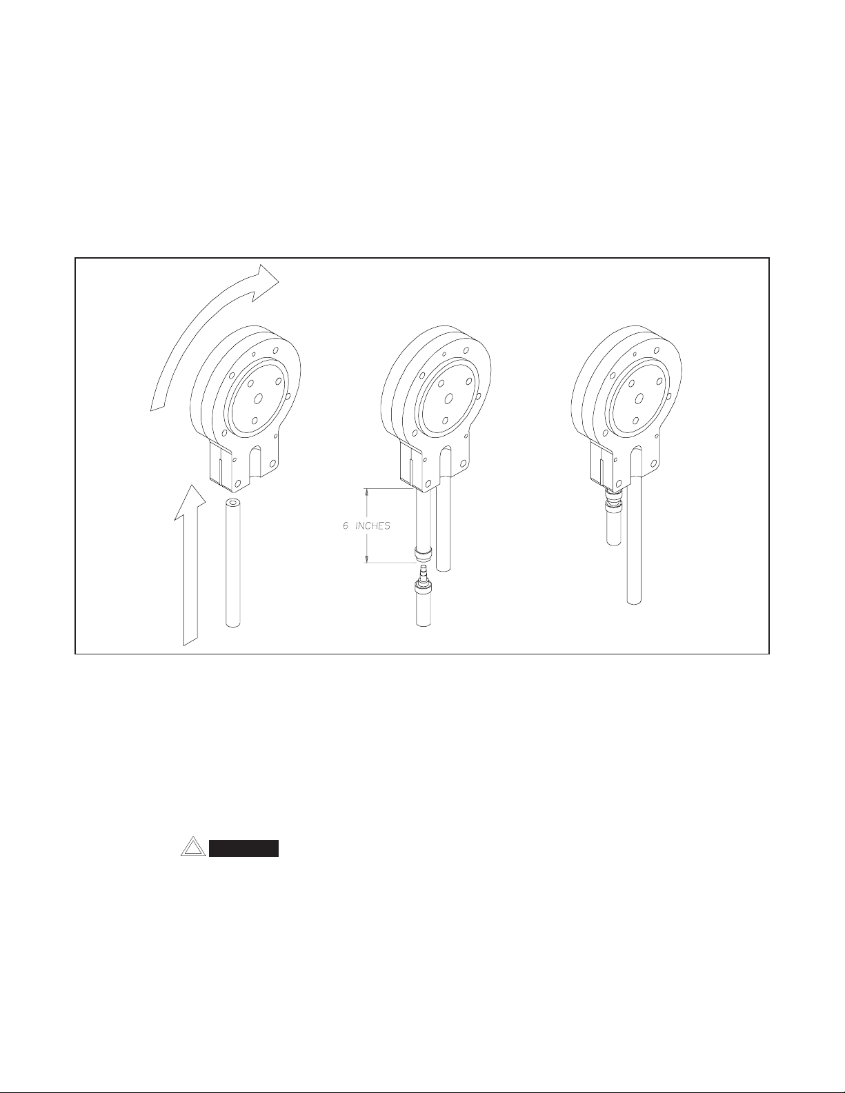
4.5 MIX PUMP HOSE REPLACEMENT
6. Use a brush that fits in the opening and brush
up and down, first with detergent water and
then clear water .
7. Connect new mix pump hose to pick-up hose
adapter, using small clamp.
8. Insert free end of hose into the pick-up (suction
side) hose side of the black cover . Gently push
the hose into the black cover until it begins to
self-feed. Allow the hose to feed itself through
the pump until the pick-up hose adapter prevents furrther feeding, then turn the pump off.
9. Reconnect mix pump hose to T using small
clamp. Pump is now ready to sanitize.
NOTE
Mix pump hose must be replaced when tubing cannot be further repositioned (every four to eight
weeks). Failure to comply will result in hose failure
and possible pump damage.
1. Run cleaning solution through pump.
2. Turn pump of f and relieve any pressure by
opening the spigot.
4.6 CAB TEMPERA TURE ADJUSTMENT
A temperature control is used to control cab temperature.
To change the temperature disconnect power sources and
then follow the steps below:
A. Remove the six screws holding the left side panel
and remove panel.
B. Use a small screwdriver to adjust the temperature
control. Turn counterclockwise for a warmer tem-
W ARNING
THE MIX PUMP SWITCH MUST BE IN THE “OFF”
POSITION WHEN SERVICING OR CLEANING
perature and clockwise for a colder temperature. It
will take about an hour for the cab temperature to
change. Figure 29.
PUMP.
24
Page 33

Figure 36. Temperature Control Cab
4.8 CONDENSER CLEANING (AIR-COOLED
FREEZERS)
The condenser requires periodic cleaning. To clean the
condenser, refer to the following steps:
NOTE
Some freezers have a condenser filter, to clean remove and wash in warm soapy water. Rinse in clean
water and shake dry, taking care not to damage
filter in any way .
A. Visually inspect the condenser for dirt.
B. If the condenser is dirty, place a wet towel under the
condenser.
C. Install side panel and secure with the six retaining
screws.
4.7 DRIVE BELT TENSION ADJUSTMENT
To check belt tension, refer to Figure 30 and follow the
steps below:
WARNING
DISCONNECT ELECTRICAL SUPPLY TO
FREEZER BEFORE SERVICING.
A. Remove either side and back panels.
B. Press firmly on one belt. Figure 30.
C. Using compressed air or CO2 tank, blow out the dirt
from the top of the condenser. Most of the dirt will
cling to the wet towel.
CAUTION
THIS PROCEDURE EMITS A LOUD NOISE.
D. An alternative method is to clean with a condenser
brush and vacuum.
NOTE
If the condenser is not kept clean, loss of refrigeration efficiency will result.
4.9 PREVENTATIVE MAINTENANCE
It is recommended that a preventative maintenance schedule be followed to keep the freezer clean and operating
properly. The following steps are suggested as a preventative maintenance guide.
WARNING
NEVER ATTEMPT TO REPAIR OR PERFORM
ANY MAINTENANCE ON FREEZER UNTIL ALL
MAIN ELECTRICAL POWER HAS BEEN DISCONNECTED.
Figure 37. Belt Adjustment
C. When the tension is properly adjusted, the outside
of the depressed belt should be approximately in
line with the inside of the other belt.
D. If an adjustment is necessary, loosen the four motor
plate retaining nuts, adjust belt tension then retighten the four nuts.
NOTE
Belt life will be increased if new drive belts are tightened after two or three weeks of operation.
The United States Department of Agriculture and the
Food and Drug Administration require that lubricants
used in food zones be certified for this use. Use lubricants
only in accordance with the manufacturer's instructions.
A. Daily Checks
Check for any unusual noise or condition and repair
immediately.
B. Monthly Checks
1. Check drive belts for wear and tighten belts if
necessary. (Refer to Section 4.7.)
2. Check the condenser for dirt. (Refer to Section
4.8).
25
Page 34

W ARNING
NEVER ATTEMPT TO REPAIR OR PERFORM
MAINTENANCE ON FREEZER UNTIL ALL MAIN
ELECTRICAL POWER HAS BEEN DISCONNECTED.
4.10 EXTENDED STORAGE
Refer to the following steps for winterizing the freezer or
for storing the freezer over any long period of shutdown
time.
A. Clean thoroughly with warm detergent all parts that
come in contact with mix. Rinse in clear water and
dry all parts. Do not sanitize.
NOTE
Do not let cleaning solution stand in freezer barrel
or mix pump during the shutdown period.
B. Remove, disassemble, and clean the front door,
auger shaft, and mix pump. Leave disassembled
during the shutdown period.
C. Place plastic auger flights in a plastic bag with a
moist paper towel. This will prevent flights from
becoming brittle if exposed to dry air over an
extended period of time (over 30 days).
D. For water-cooled freezers that are left in unheated
buildings, or buildings subject to freezing, the water
must be shut off and disconnected. Disconnect
fittings at water valve inlet and water outlet lines at
the freezer. The fittings are located at the rear of the
freezer. Run the compressor for 2 - 3 minutes to
open water valve. Blow out all water, first through
water inlet, then through water outlet lines with air or
carbon dioxide. Also drain water supply line to the
freezer.
E. Place the mix pump ON-OFF switch, and the freezer
CLEAN-OFF-SERVE switch in the OFF position.
F. Disconnect from the source of electrical supply in
the building.
26
Page 35

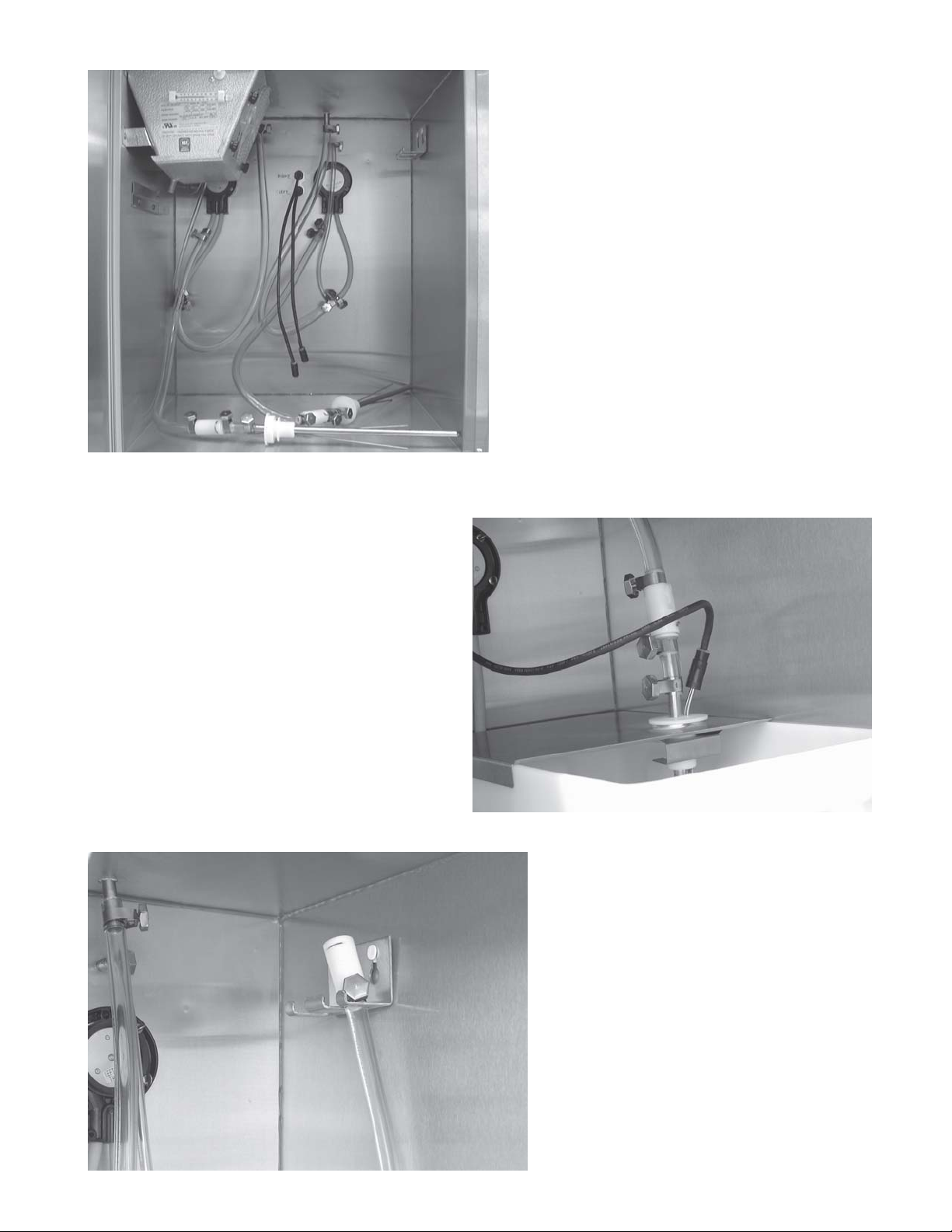
4.11 FREEZER REFERENCE PHOTOS
LEFT SIDE
RIGHT SIDE
27
Page 36

REAR UPPER
REAR LOWER
28
Page 37

AIR COOLED TOP
OVERRUN ADJUSTMENT
29
Page 38

30
Page 39

SECTION 5
REFRIGERATION SYSTEM
5.1 REFRIGERATION SYSTEM
The refrigeration system is designed for efficient use with
the refrigerant and charge shown on the nameplate.
Figure 31.
Figure 39. Terminal Cover Removal
3. Remove wires C, R, and S at compressor.
Figure 33.
Figure 38. Nameplate
5.2 COMPRESSOR
The compressor is designed specifically for use with the
refrigerant shown on the nameplate.
A. Winding Test
To test the compressor motor windings for possible problems, perform the following steps:
W ARNING
DISCONNECT FREEZER FROM ELECTRICAL
SUPPL Y BEFORE SERVICING.
1. Remove the Philips head screws from the side
panels and slide the side panels down and out.
2. Remove the compressor terminal cover by inserting standard screwdriver between the terminal
cover and retaining frame, pry out side then hold
with your hand while prying the other side then
remove cover. Figure 32.
Figure 40. Compressor Connections
4. Connect ohmmeter to terminals C and R. To
check resistance through run windings, set your
ohmmeter to X1. Consult your Service Data Manual
for the proper value.
5. Connect ohmmeter to terminals C and S. To
check resistance through the start windings, set
your ohmmeter to X1. Consult your Service Data
Manual for proper value.
6. To check if windings are shorted to ground, connect one ohmmeter lead to a bare metal part on
the compressor, such as any copper line leading
to or from the compressor and checking terminals
C, R, and S.
31
Page 40

NOTE
The compressor is equipped with an internal overload protector . If the compressor is warm and ohmmeter readings indicate an open winding, allow up
to one hour for overload to reset.
5.3 CONDENSER
The condenser is a water cooled tube and shell type.
Condensing is totally dependent on water supply. Water
flow to the condenser for controlling head pressure is
regulated by a water valve. The water supply must not be
restricted on either the inlet or outlet. Air cooled models
must have adequate clearance for proper air flow.
W ARNING
DISCONNECT FREEZER FROM ELECTRICAL
SUPPL Y SOURCE BEFORE SER VICING .
3. Connect the freezer to the electrical supply, start
the refrigeration cycle and read the pressure.
4. The proper gauge reading should be 25-31 P.S.I.G.
(404A) at 75°F ambient temperature just prior to
shut off. If the readings are not within these
parameters, continue following these steps:
NOTE
To adjust the side panel must be removed. Before performing the following procedures be absolutely certain it
is necessary to adjust the T.X.V.
5. Remove the cap on the T.X.V. and, using a service
wrench, turn the valve stem 1/4 (90°) turn
counterclockwise for more cooling or clockwise
for less cooling. Figure 34.
5.4 EVAPORATOR
The evaporator is a flooded type. It has a stainless steel
inner shell with a solid aluminum wrap and a stainless steel
outer shell shrunk over it. The insulation is a foam type.
A. T.X.V. Adjustments
A T.X.V. (Thermostatic Expansion Valve) is used to meter
the refrigerant to the evaporator. The self-regulating T.X.V.
is preset at the factory. Figure 34.
6. Should the reading still not reach 25-31 P.S.I.G.,
repeat step 5 until the correct reading is obtained.
7. Once the 25-31 P.S.I.G. reading is obtained,
replace the cap on the T.X.V., remove the pressure gauge and replace the low side Schrader
valve cap.
B. T.X.V. Removal
CAUTION
IF THE T.X.V. IS REPLACED, A HEAT SINK (WET
CLOTH) MUST BE USED TO PREVENT DAMAGE TO
THE V AL VE.
WARNING
DISCONNECT FREEZER FROM ELECTRICAL SUPPL Y
SOURCE BEFORE SERVICING.
1. Assuming the left or right side panel is removed,
perform the following procedures for removing the
T.X.V .
2. Remove bulb from suction line exiting from the
evaporator .
Figure 41. Expansion Valve
To determine whether or not the T.X.V. is in need of
adjustment, perform the following procedures:
NOTE
There are two T .X.V .’ s one for each side.
W ARNING
DISCONNECT FREEZER FROM ELECTRICAL
SUPPL Y SOURCE BEFORE SER VICING .
1. Remove the Philips head screws from the right
side panel and slide the panel down and out.
2. Remove the cap from the low side Schrader valve
and install a 0 to 100 P.S.I.G. gauge.
3. Recover refrigerant charge and leave a port open
to prevent pressure build-up during T .X.V . removal.
4. Remove any insulation from the T .X.V . and immediate surrounding lines.
5. Remove or push back any foam insulation from
surrounding lines.
6. Apply a heat sink (wet cloth) to the valve dome.
Figure 35.
7. Unsweat the suction line and liquid line from T .X.V .
and remove the T.X.V . with heat sink.
32
Page 41

Figure 42. Expansion Valve Removal
C. T.X.V. Replacement
T o replace the T .X.V., perform the following procedures:
CAUTION
WHEN REPLACING THE T.X.V., A HEAT SINK
(WET CLOTH) MUST BE USED TO PREVENT
DAMAGE TO THE V AL VE.
1 1.Recharge system to nameplate specification.
NOTE
The T.X.V. bulb should ALWAYS be mounted on
the horizontal line (opposite from the sensor), with
the capillary end facing the flow of refrigerant. Good
contact between the bulb and the suction line is
necessary for proper operation of the valve. The bulb
must also be well insulated.
12.Install bulb on suction line exiting the evaporator.
1. Position the T .X.V., with heat sink, so the liquid
line and suction line correspond with the proper
valve points.
2. With an open port braze the liquid line and suction line to the T .X.V. using appropriate brazing
material.
3. Remove the heat sink from the T .X.V .
4. Replace any foam insulation to the surrounding
lines.
5. Replace any insulation to the T .X.V . and immediate surrounding areas.
6. Purge and evacuate the system.
7. Break the vacuum to 0 pounds per square inch
with dry nitrogen.
8. Remove the dryer by cutting the refrigeration lines
then with an open port sweat in the replacement
dryer. Make cert ain the arrow points in the direction of flow .
9. Triple evacuate the system. Evacuate twice to
1500 microns of mercury , breaking the vacuum
each time with dry nitrogen. Then evacuate to 500
microns of mercury .
Figure 43. Drier
D. Water Valve Adjustment
To determine whether or not the water valve is in need of
adjustment, perform the following procedures:
NOTE
There are two valves-one for each side.
WARNING
DISCONNECT FREEZER FROM ELECTRICAL
SUPPL Y SOURCE BEFORE SER VICING .
1. Remove the Philips head screws from the upper
back panel and remove panel.
2. Remove the cap from the high side Schrader valve
and install a 0 to 500 P.S.I.G. gauge.
3. Connect the freezer to the electrical supply, start
the refrigeration cycle, and read the pressure.
4. The proper gauge reading should be approximately
220 to 230 P.S.I.G. This would result in an exit
water temperature of approximately 95-107°F .
T o adjust the water valve, turn the adjustment
screw counterclockwise to increase head pressure and clockwise to decrease head pressure.
10.Replace insulation.
33
Page 42

E. Water Valve Removal
W ARNING
DISCONNECT FREEZER FROM ELECTRICAL
SUPPL Y BEFORE SERVICING.
Assuming the necessary panels are removed, perform the
following procedures for removing the water valve.
7. Triple evacuate the system. Evacuate twice to
1500 microns of mercury , breaking the vacuum
each time with dry nitrogen. Then evacuate to 500
microns of mercury .
8. Replace insulation.
9. Recharge system to nameplate specification.
1. Turn off and disconnect the water supply and drain.
Blow out the water lines with compressed air or
CO2.
2. Recover the refrigerant charge and disconnect the
capillary tube.
Figure 44. Water Valves
3. Remove the water lines from the valve. Figure 37.
10.Connect the water supply line and turn on the
water.
1 1.Check for leaks.
12.Replace the side panel and connect to the source
of electricity.
5.5 CAB UNIT
The cab is refrigerated using the left side compressor. If
the compressor is not running to freeze the barrel it will
be activated by a separate temperature control as needed
to keep the cab cool. The cab is independent of the main
control system and will maintain temperature even if the
left and/or right side of the freezer is not in use.
T o adjust temperature perform the following procedures:
1. Remove the six phillips head screws from the left
side panel, then pull the panel down and out.
2. Use a straight bladed screwdriver to turn the
temperature control clockwise for a colder
temperature and counterclockwise for a warmer
temperature.
4. Remove the two screws holding the water valve
to the frame and remove the valve.
F. Water Valve Replacement
To replace the water valve, perform the following procedures:
1. Position the water valve and attach to the frame
using the two screws.
2. Connect the water lines to the valve.
3. Connect the capillary tube.
4. Purge and evacuate the system.
5. Break the vacuum to 0 pounds per square inch
with dry nitrogen.
6. Remove the dryer by cutting the refrigeration lines
then with an open port sweat in the replacement
dryer. Make cert ain the arrow points in the direction of flow .
3. Replace side panel.
NOTE
It takes approximately 15 minutes for the temperature to
change. If going from colder to warmer leave the cab door
open for a few minutes then close and wait 15 minutes.
34
Page 43

SECTION 6
ELECTRICAL CONTROL SYSTEM
6.1 CONTROL SYSTEM
The control system is the "brain" of the freezer . T o understand how to service the freezer , it is essential to understand how the control system operates. The control system used on the Model U431 Freezer has one temperature control per barrel.
NOTE
The cab has a separate temperature control found
behind the left side panel.
To gain complete access to the front control box and its
components, perform the following procedures:
1.Loosen the two Phillips head screws from the bottom of
the decorative panel and pull the panel out and down.
The front control box and its components are now completely accessible and any necessary testing and adjusting can now be done. Figures 38 and 39.
NOTE
Subsections 6.1 through 6.6 will deal specifically
with the control system.
To provide easier access to components inside or on the
back side of the electrical box, remove the four phillips
head screws holding the box to the frame. The electrical
box can now be positioned as necessary to service the
components. The side panel can be removed to aid in
positioning the box for servicing. Figure 40.
Figure 45. Front Electrical Box
Figure 46. Front Electrical Box Close Up
Figure 47. Electrical Panel Screws
A. Indicator Lights
1. The red indicator light when illuminated indicates that
the temperature control is receiving power.
2. The yellow light when illuminated indicates that the high
temperature relay (day/night, cut in at 29°F, out at
19°F) has been activated.
3. The green light when illuminated indicates that the low
temperature relay (serve position, cut in at 22°F, out at
6°F) has been activated.
B. Sequence of Operation
1. The red light is illuminated whenever the board is
furnished with power.
2. At start-up, power to the freezer is switched on (any
temperature) - red and yellow come on.
a. If the standby-serve switch is in "serve position",
then as the high relay low set point is satified, the
yellow light goes off. Green light illuminates. When
low relay low set point is satisfied, green light goes
off. Yellow and green are both off. The green light will
cycle on and off with the system upon spigot opening
or call from the temperature sensor.
35
Page 44

b. If the standby-serve switch is in the "standby
position", then as the high relay low set point is
satisfied, the yellow light goes off; the green light
illuminates. On the next temperature cycle, when
refrigeration is required, the yellow light will illuminate as the compressor starts and the green light will
go out. When satified, the yellow light goes out, and
the green light illuminates.
3. When the freezer is in the normal serve mode (not initial
start-up) and the yellow and green lights are off.
a. Switch from "serve" to "standby". When the low relay
high point is reached, the green light will illuminate,
but no equipment is switched on. When the high
relay high set point is reached, the yellow light
illuminates as the compressor starts and the green
light goes out. When the high relay low set point is
satisfied, the yellow light goes out and the green light
illuminates, and they alternate like this until switched
back to the "serve" mode.
4. Freezer in the normal night mode. Yellow light off; green
light on.
a. Switch from the "standby" to the "serve" mode. The
green light remains illuminated while the compressor
runs. When the low relay low set point is satisfied,
the green light goes out. Both lights are now off.
C. Temperature Control Sensor
The thermistor sensor is used to sense the temperature of
the suction line. As the suction line temperature decreases, the internal resistance of the thermistor will
increase. The temperature control board will compare the
thermistor resistance with an established resistance on
the control board. When the resistances are equal, the
circuit board will shut off the compressor. A phenomenon
in the thermistor sensors is that resistance values can be
different at any given temperature depending upon whether
the temperature (just before a reading is taken) has been
rising or dropping. Readings are especially difficult to
predict if the temperature is rising. However, if the temperature is dropping, resistances are predictable. Therefore,
before checking the resistance in a sensor, always make
certain the temperature in the sensor is dropping. When
troubleshooting a sensor, remove the blue wire from the
circuit board and the blue wire from the night/serve switch
or terminal board. The internal resistance between the two
wires should be 1,000 +/- 400 ohms when the sensor is at
70°F. If the resistance is not within this range, replace it.
In most cases, if there is a sensor failure, it will be shorted
out (0 resistance) or open (infinite resistance).
6.2 CURRENT SENSOR
The current sensor is used to activate the condenser fan
contactor (air cooled only).
6.3 CONTACTORS
The compressor and drive contactors are mounted inside
the electrical box. The left side compressor has two
contactors. One contactor activates the compressor to
freeze the barrel and the other contactor activates the
compressor to cool the cab. The right side compressor and
the two drive motors have one contactor each. There is one
contactor to start the condenser fan motors (air cooled
only).
The temperature control sends an electronic signal to
trigger the contactors. The electronic signal tells when to
operate the contactor for the compressor. A separate
signal is used to control the drive motor contactors. The
signals to the contactors are staggered so the drive motor
will always start and stop two or three seconds before the
compressor and condenser fan. By staggering the stopping and starting of the drive motor, maximum starting
torque is available and voltage spikes are reduced. The
condenser fan motor contactor gets it's signal from a
current sensor (air cooled only).
6.4 DRIVE MOTOR
The drive motors are designed specifically for the U431
freezers. The drive motors are used to rotate the auger
assemblies. For single phase, the start and run capacitors
are located on the motor. An internal, normally closed,
centrifugal switch starts the drive motor. The motors have
an internal thermo overload.
36
Page 45

SECTION 7
MAJOR COMPONENT REMOVAL AND INSTALLATION
7.1 PREP AR ATION FOR COMPONENT REMOVAL
The procedures set forth in the section MUST be followed completely and in the order in which they appear.
To remove any or all of the major components of the
freezer, remove necessary panels.
WARNING
DISCONNECT FREEZER FROM ELECTRICAL
SUPPLY SOURCE BEFORE SERVICING.
1. Remove the Phillips head screws from each side
panel and remove the side panels by pulling down and
out.
2. Remove the Phillips head screws from the back panel
and remove the back panel by pulling down and out.
3. Remove the eight Phillips head screws from the top
panel and lift off.
4. Remove the two 1/4" cap screws and remove the
blockoff panel to access the fan motors (air cooled
only). Figure 41.
7.3 DRIVE MOTOR REMOVAL
1. Remove the electrical wires from the motor.
2. Loosen and remove the belts. Figures 42 and 43.
Figure 49. Drive Motor and Belt Removal
3. Remove the four mounting bolts and remove the motor
through the rear of the freezer. Figure 43.
ÅÅ
Å
ÅÅ
Blockoff Panel
Figure 48. Block Off Panel
7.2 COOLING FAN MOTOR REMOVAL
After the ELECTRICAL SUPPLY HAS BEEN DISCONNECTED and the previous steps have been completed,
the fan motor can be removed by performing the following
procedures:
1. Disconnect the wires leading from the fan motor.
4. Loosen the two allen head screws and remove the
pulley.
ÊÊ
Ê
ÊÊ
ÉÉ
É
ÉÉ
Mounting
ËË
Ë
ËË
Bolts
ÌÌ
Ì
ÌÌ
ÊÊ
Ê
Bolts
ÊÊ
ÌÌ
Ì
ÌÌ
Adjustment
Figure 50. Drive Motor Removal
7.4 GEAR BOX REMOVAL
1. Loosen and remove the belts Figures 42 and 43.
2. Remove the pulley by loosening the allen head screws
and remove the pulley.
ÉÉ
É
ÉÉ
Adjustment
Bolts
ËË
Ë
ËË
2. Remove the four hex nuts securing the fan bracket
to the frame.
3. Remove the fan and bracket through the top of the
freezer.
3. Remove the four bolts holding the gear box to the
barrel. Figure 44.
4. Remove the two bolts holding the gear box to the
mounting bracket and remove the gear box through
the rear of the freezer.
37
Page 46

Figure 51. Gear Box Removal
7.5 COMPRESSOR REMOVAL
After the ELECTRICAL SUPPLY HAS BEEN DISCONNECTED, and the panels have been removed, the compressor can be removed by performing the following
procedures:
1. Remove the compressor terminal cover by inserting a
standard screwdriver under the terminal cover retaining clip and gently pry off. Figure 45.
3. Recover refrigerant charge and leave a port open to
prevent pressure build-up during compressor removal.
4. Remove six inches of insulating tubing on the suction
line going to the compressor and unsweat the suction
and discharge line from the compressor.
5. Remove the four nuts and washers from the base of
the compressor.
6. Remove the compressor through the side of the freezer.
7. Remove the four rubber compressor mounts from the
old compressor.
NOTE
Rubber mounts are not always furnished with replacement compressor.
8. Check the compressor for a burn-out condition using
an acid test kit. If acid is found, clean out the system
per the compressor manufacturer's instructions.
9. Plug all open ports of the old compressor.
NOTE
A compressor returned to the company with any open
ports will void the warranty. AL W A YS plug any ports on a
compressor that has been removed.
Figure 52. Compressor Connections
2. Identify and remove the three wires from inside the
compressor electrical box. Figure 46.
7.6 COMPRESSOR INSTALLATION
After the ELECTRICAL SUPPLY HAS BEEN DISCONNECTED, all panels have been removed, and the old
compressor has been removed, the replacement compressor can be installed by performing the following
procedures:
1. Before the replacement compressor can be installed
the entire refrigeration system must be thoroughly
purged.
CAUTION
IF ACID IS FOUND IN THE SYSTEM, CLEAN OUT PER
COMPRESSOR MANUFACTURER'S INSTRUCTIONS.
2. Install the four rubber compressor mounts on the
replacement compressor.
3. Install the replacement compressor into the freezer,
fitting the base over the four bolt holes.
4. Install the four washers and nuts onto the bolts and
tighten securely.
5. Remove all plugs from the replacement compressor.
Figure 53. Compressor Connections
6. Leaving a port open to prevent pressure build-up,
braze the suction and discharge line to the compressor.
38
Page 47

Figure 54. Drier
7. Connect the wires in the compressor electrical box
and install the electrical box cover and retainer.
8. Purge and evacuate the system.
9. Break the vacuum to 0 P.S.I.G. with dry nitrogen, then
open an access port.
10. Remove the dryer by cutting the refrigeration lines,
then with an open port sweat in the replacement drier.
Make certain the arrow points in the direction of
flow. Figure 47.
2. Fasten the two bolts through the mounting bracket at
the rear of the freezer.
3. Mount the pulley on the gear box shaft and align with
the motor pulley, then tighten the allen head set
screws.
4. Tighten the drive belts. Figure 49.
Figure 56. Belt Tension
7.8 DRIVE MOTOR INSTALLATION
1. Place the drive motor in position from the rear of the
freezer and install the four mounting bolts.
11. Triple evacuate the system. Evacuate twice to 1500
micons of mercury, breaking the vacuum each time
with dry nitrogen. Then evacuate to 500 microns of
mercury.
12. Replace insulation.
13. Recharge system to nameplate specifications.
14. Leak check all fittings and connections.
15. Replace the six inches of insulating tubing to the
suction line.
7.7 GEAR BOX INSTALLATION
1. Place the gear box in position from the rear of the
freezer and fasten the four bolts through the gear box
to the rear of the barrel. Figure 48.
2. Mount the pulley on the motor shaft and align with the
gear box pulley. Then tighten the two allen head
screws.
3. Tighten drive belts. Figure 49.
7.9 CONDENSER FAN MOTOR INSTALLATION (AIR
COOLED)
1. Install the fan motor through the top of the freezer
(Figure 50) and position in place.
2. Install the four hex nuts and tighten securely.
3. Connect the wires leading from the fan motor.
Figure 55. Gear Box Removal
Figure 57. Motor Installation
39
Page 48

7.10 FINAL ASSEMBLY OF FREEZER
Upon completion of the removal and installation of any or
all of the major components of the freezer, the panels can
be replaced by performing the following procedures:
1. Position the back panels into place and install the
Phillips head screws, tighten securely.
2. Position the right side panel into place and install the
Phillips head screws through the side panel and tighten
securely.
3. Position the block off panel and secure with the two
1/4" cap screws.
4. Position the left side panel into place and install the
Phillips head screw through the side panel and tighten
securely.
5. The freezer electrical supply can now be connected.
40
Page 49

8.1 Troubleshooting - Freezer
MELBORP ESUACELBISSOPREZEERF YDEMER
SECTION 8
TROUBLESHOOTING
)regua(rotomevirD
tonseodro,"tuo-skcik"
.nur
enilwoL.3
tonseodrosserpmoC
.etarepo
.tfosoottcudorP.hgihootsignitteserutarepmeT.1
lliwtcudorP(.pu-ezeerF
).ylisaeesnepsidton
tomevirD.2
.tuo-tuc
reS-ybdnatS.3
.noitisop
rrevowoL.2
ktimiltogipS.6
.ffosirezeerfotrewoP.1
.dedaolrevorotomevirD.2
.egatlov
.drahoottcudorP.4
.ylerucesdellatsnitonroodtnorF.5
.fforezeerfotrewoP.1
.dedaolrevoro
.egatlovenilwoL.3
sidaolrevolanretnirosserpmoC.4
.ylerucesdellatsnitonroodtnorF.5
.nwodkaerbtcudorP.2
ybdnatSnihctiwSev
.wolootsignitteserutarepmeT.1
.gnittesnu
.erusserppmupwoL.3
.lerrabnitekcopriaegraL.4
.esiwkcolc-retnuocgninrutreguA.5
.evitcirtsersbon
02-51tiaW.2
.teserot
.teser
.egatlov
dnatSecalP.3
.noitisop
.rezeerfotrewopkcehC.1
daolrevoomrehTrof.nim
fo%01-\+ebtsum,kcehC.3
.egatlovetalpeman
tcudorpro/dnanurrevoesiaR.4
eeS(.erutarepmet
.ylerucesroodtnorfllatsnI.5
.rez
eerfotrewopkcehC.1
.yleru
cesroodtnorfllatsnI.5
.tcudorphserfhtiwlliF.2
.erusserppmupkcehC.3
errabmorfriaegruP.4
.l
.esiwkcolcotnoitatoregnahC.5
)2.4ro3.4noitceS
otdaolrevoomrehTrof.nim02-51tiaW.2
etalpemanfo%01-/+ebtsum,kcehC.3
.tce
SeeS()deloocria(resnednockcehC.4
.)deloocretaw(yppusretawro,)8.4
)ylnOhP1(yalerdnasroticapackcehC
)2.4noitceSeeS(.erutarepmettsujdA.1
evreSnihctiwSevreS-yb
)2.4noitceSeeS(.erutarepmettsujdA.1
)launampmupeeS(.nurrevoesiaR.2
.etarwolfretsafroftnemtsujdaetarnepO.6
aeR.detacirbultonlaesreguaraeR.1
.skaeltogipS.detacirbultonerastraptogipS.1
sstlebevirD
.gnilaeuqs
.bacnimraw
.bacnidloc
.skaellaesreguar
rognippil
ooterutarepmetxiM
oo
terutarepmetxiM
laesetacirbuL.1
.gnorwdellatsnirognissimlaeS.2
.tfahsdehctarcsronroW.3
.sgnir
-onrowrodeppihC.2
.gnorwdellatsnitogipsnosgnir-O.3
roodtnorfnodehctarcsroskciN.4
.detacolsitogipserehw
.tcerroctonnoisnettlebevirD.1
.)s(tlebnroW.2
.wolootsignitteserutarepmeT.3
woL.4
.nurrevo
.tnaregirfernowolmetsyS.1
ootteslortnocerutarepmeT.2
.mraw
.dlocootteslortnocerutarepmeT.1 etacoldnalenapedistfelevomeR.1
kcehC.4
.tfahsecalpeR.3
.sgnir-oecalpeR.2
.roodtnorfecalpeR.4
.stlebecalpeR.2
.kaelriarof
cerutarepmet
)31.3noitceSeeS(.kcehC.2
1.3noitceSeeS(.etacirbuL.1
rfeR(.tnaregirferddA.1
.lacednosnoitcurtsni
.lacednosnoitcurtsni
)31.3noitceSeeS(.
)3
.sgnir-okcehcdnatogipsevomeR.3
)7.4noitceSeeS(.noisnettlebtsujdA.1
)2.4noitceSeeS(.erutarepmettsujdA.3
)ecivreS.gi
etacoldnalenapedistfelevomeR.2
wollofdnalortnocerutarepmet
wollofdnalortno
41
Page 50

Pressures and Temperatures
Same as Left
Water Cooled Version
-10° to -18°F
(-23° to -28°C)
Evaporating Temp.
Mount bulbs at 3:00 and 9:00
8.2 Refrigeration Drawings
Super Heat - 6 to 11°F
(-14.4° to -11.7°C)
69-71 PSIG
(5 bar)
42
18-24 PSIG @ Capacity
(1.3 - 1.7 bar)
25-30 @ Shutoff (2 bar)
Head Pressure
230 PSIG (16 bar)
(30.7 bar)
Trips at 445 PSIG
Page 51

Pressures and Temperatures
Same as Left
Air Cooled V ersion
Super Heat - 6 to 11°F
Mount bulbs at 3:00 and 9:00
(-14.4° to -11.7°C)
-10° to -18°F
(-23° to -28°C)
Evaporating Temp.
69-71
PSIG
(5 bar)
43
Head Pressure
215-230 PSIG Both
(15 to 16 bar)
Sides Running May
*18-24 PSIG @ Capacity
(1.3 - 1.7 bar)
25-30 @ Shut Off (2 bar)
Be Up To 240 PSIG
(16 bar)
(30.7 bar)
Trips at 445 PSIG
*w/Cab. & Evap. Calling For Refrig. Add 10 PSIG
Page 52

8.3 Troubleshooting - Mix Pump
MELBORP ESUACELBISSOPREZEERF YDEMER
seodrotompmuP
.nurton
.egatlovwoL.2
.ffosipmupotrewoP.1
.pmupotrewopylppuS.1
.egatlovwolrofkcehC.2
demmajesohpmupxiM.3
.pmalc/revockcalbedisni
arapeS.swercsbmuhtpmalc/revoc
ruofevomeR.ecruosrewopmorfpmuptcennocsiD.3
pmalc/revocet
.esohdemmajevomeR.flahretuoevomerdnasevlah
ni-erdnanaelC
ruofnethgitdnapmalc/revocllats
daolrevolamrehtrotomwollA.ylerucesswercsbmuht
tonoD.tnemecalperesohrof2.4.ceSeeS.teserot
.
esohfonoitropdemmajesu
.
dedaolrevorotompmuP.4
enimreted;teserotdaolrevolamrehtlanretniwollA.4
.riaperdnaesuacdaolrevo
sipmupnohctiwserusserP.5
.evitcefed
.hctiwserusserp
nocdnanoitarepolacinahcemkcehC.5
.roticapac/rotomevitcefeD.6
tomecalpeR
feD.7
.hctiwselggotevitce
.roticapacroro
.ecalperroriaper;ytiunitnockcehC.7
setarepopmuP
tonlliwrednilyctub
.SDNOCES
foytiunit
.roticapacro/dnawardegarepmarotomkcehC.6
9TUOBANIXIMHTIWPUC.ZO8NALLIFLLIWPMUPGNIKROWYLREPORPA:1ETON
.llif
-EROTELBANUEBYAMPMUPEHT"EGNAHCGAB"ARETFAYLETAIDEMMI:2ETON
,ESACSIHTNI.ERUSSERPGNITAREPOTAMETSYSEHTHTIWEMIRPS'TIHSILBATSE
RD.FFOPMUPEHTNRUT
.OREZOTERUSSERPMETSYSECUDEROTSTNIP3-2WA
.ESOHPU-KCIPDNAGABXIMNIRIAGNINIAMEREGRUP.NOPMUPNRUT
kcipehtgnitcennocerofeB:TNATROPMI
gabximehtegrup,gabximehtotesohpu-
.elbissoptnetxeehtotriafo
.xiMfotuO.1
edisnideknikesohpmupxiM.2
revockcalb
.pmalc/
.yltcerrocnidelbmessasesoH.3
efeR.3
siefilecivresesohpmupxiM.4
ylppusximhsinelpeR.1
.
).evoba1#eeS(.riaperdemmajesohpmupximwolloF.2
.snoitcennocesohtcerrocrofmargaidotr
.2.4.ceSeeS.esohpmupximecalper/noitisopeR.4
.dedeecxe
detcennoctonesohpmupxiM.5
.re
zeerfot
.ximnislatsyrcecI.6
elpmoC.6
tsniaganwardgabxiM.7
.rezeerfotesohpmupximtcennoC.5
.esuotroirpximwahtylet
.ebutpu-kcipforaelcsigaberussA.7
.retpada
.ximnistcejbongieroF.8
.sdrawkcabsievlavkcehC.9
rowolootnurrevO
.nurrevoon
.kaelriA.2
.wolootgnittesnurrevO.1
gnipmuptonrosserpmocriA.3
esbO.9
.spmalcesohllanethgiT.2
3
.ximhserfesU.egakcolbraelC.8
.noitatneiroreporprofworrawolfevr
.gnittesnurrevoesaercnI.1
.rotubirtsiDgnitleotSlacoltcatnoC.
.ria
.hgihootnurrevOsiefilecivresesohpmupxiM.1
abnievlavkcehcriA.4
.sdrawkc
.wolffonoitceridrofworrakcehC.4
.esohpmupximecalper/noitisopeR.1
.dedeecxe
.ximfotuO.2
nittesnurrevO.3
.hgihootg
esohpmupximfogelpu-kciP.4
peR.2
.ylppusximhsinel
.gnittesnurrevoesaerceD.3
.esohnoitisopeR.4
.gnispallocsi
.EVOBA"2"EESOSLA:ETON
44
Page 53

MELBORP ESUACELBISSOPREZEERF YDEMER
ximtnemecalpeR
t'nowesohpmup
hguorhtdeef
.pmup
ximgnitixeriA
.esohpu-kcip
tcudorpdesnepsiD
"spop"ria
morfegakaelxiM
.pmup
onsdneesoH.2
.gnissim
.d
edeecxe
.yticapac
.dedeecxe
egrahcsidotniesohgnideeF.1
.revocpmupximfoeloh
.ylerauqstuct
.ylkciuqootgnideefecroF.3
.revocfoedisesoh
.gninnurtonrotompmuP.4
evlavkcehcebutpukciP.1
.hgihootgnittesnurrevO.1
siefilecivresesohpmupxiM.2
s'rezeerfehtgniwardrevO.3
.noitidnoc"tuo-xim"tneceR.4
.evobA"2"eeSoslA:ETON
.
pmupnaelcdnaelbmessasid
siefilecivresesohpmupxiM.1
niraeb
DgnitleotSlacoltcatnoC.1
ecalper/noitisopeR.1
.etaresnepsidecudeR.3
naylluftogipsnepO.4
.woleb01#metIees,sg
.revocfoedisnoitcusotniesohdeeF.1
.)sliaton(ylerauqsffodneesohtucylluferaC.2
pu-kcipotnipuesohfognideeftsissaylwolsdnayltneG.3
.ev
oba1metIeesoslA.hctiwsrotomnonruT.4
.rotubirtsi
.esohpmupxim
.esohpmupximecalper/noitisopeR.2
.tuo"hcleb"otriassecxewollad
yletaidemmi,stisopedximdeirdmorfegamadpmupximtneverpoT:NOITUAC
rewopmorfpmuptcennocsiD.esohpmupximevomeR.1
YLHGUOROHT.pmalc/revocpmupximevomeR.ecruos
dellifelttobyarpsagnisusrellorezeeuqseerhtesnir
ximllanaelcylhguorohT.retawtohhtiw
eeS.pmupmorf
rellorezeeuqsetacirbuL.tnemecalperesohrof2.4.ceS
roopsahpmuP
.yticapac
sipmuP
.gnikaeuqs/ysion
ianixiMkcalbevobaeetxim/riA.1
.sesohr
erastimilnurdnatfiL.1
.dedeecxe
.7&6,4,2eeSoslA:ETON
LP
D.ESOH
ESABENOCILISYARPS
.RAEWGNIRAEB
.pmalc/revoc
.kaelriA.2
eetxim/riagnorwnoesohxiM.3
.gnittif
usserP.4
.kaelgnir-o
dlofinamlortnocer
ipmuP.1
OGNIRUDDNUOSGNIKCILCEVITITEPER
SSID/GNINAELCESUTONOD:NOITUAC
.spmalcesohllanethgiT.2
rrocrofmargaidotrefeR.3
.nur'02,tfil'01otdetimils
ASETAERCMRAGNIKCORROSSERPMOCRIAEHTFONOITCAEHT:ETON
.LAMRONSISIHT.NOITAREP
ESUHCIHWSRELLOREZEEUQSEERHTSAHPMUPXIMCITLATSIREPEHT:ETON
THTIWSTSIXEGNIKAEUQSFI.SGNIRAEBGNITACIRBULFLES
RUOFEVOMER.REWOPLACIRTCELEMORFPMUPTCENNOCSI
.DEDEENSATAEPER.SGNIRAEBOTNITNACIRBULKROWOTSRELLORNIPS
.pmalc/revockcalbwolebebtsumeetxim/riA.1
.snoitcennocesohtce
NIESOHPMUPXIMEH
SGNIRAEBRELLOREZEEUQSEHT,DEVOMERESOHEHTHTIWSPOTSDNA,ECA
PMUPXIMEHTEVOMER.YARPSDESABENOCILISAGNISUDETACIRBULEBNAC
.TINUENOSAPMALC/REVOCERITNEEVOMER.SWERCSBMUHTPMALC/REVOC
.RELLOREZEEUQSHCAEFODNEHCAENOTNACIRBULD
.04-DWEKILSTNACIRBULEPYTGNIVLO
ETARELECCALLIWDNAYLDNEIRFGNIRAEBTONERASTNACIRBULESEHT
.deriuqersaecalper;dlofinamdnagnir-okcehC.4
45
Page 54

8.4 TROUBLESHOOTING THE CHALLENGER TEMPERATURE
CONTROL AND SENSOR
The specifications given are for the
circuit Board PN 296657 using the
1/8” x 1” stainless steel sensor with
blue wires.
This is a guide to troubleshooting the challenger type temperature control with out removing the sensor wires and therefore allowing the
freezer to run while checking. Using this method
you can determine if the problem is the sensor ,
circuit board or super heat setting. We have
found many good sensors are replaced because the ohm reading was not correct, when in
fact it wasn’t the sensor at all; the superheat
was to high or low causing that reading. Using
the control voltage reading after the potentiometer and sensor , and the suction gas temperature we can pinpoint the problem.
FOLLOW THE STEPS BELOW TO
TROUBLESHOOT:
• Verify voltage at terminals 1&2 on the
circuit board. The voltage should be about
24 volts AC.
• Check serve potentiometer, it must be set
at 2000 ohms, (Be sure power is off) (Fig.
1).
• Connect Volt/ohm meter to terminal 8 and
2nd solder spot (Fig. 2). You must have
good contact. The meter should read volts
(V) DC not milli volts (mV).
• Remove insulation from around suction
line at rear of evaporator (barrel). Make
sure line is clean; we need a good clean
contact surface. Turn on thermometer and
firmly press the surface probe to the
suction line to read suction temperature. If
you have a clamp type surface probe,
clamp to suction line (Fig. 3 & 4). Read
meters on off cycle after 1 minute. Note:
Clamp on meters will yield the most
accurate measurements.
Warning Disconnect From
Source Of Electrical Supply
Before
Servicing
• Freezer must have a full barrel of product
and be frozen down if possible.
• Remove front header panel and side
panel.
• Compare the voltage reading to the suction gas temperature using the chart found
on page 3-62.
46
Page 55

FIGURE 1
FIGURE 2
47
Page 56

FIGURE 3
48
Page 57

Control Circuit V olt s at Terminals 1 and 2 = 24 volts AC
Challenger Series - Models U431, 237R/238R, 217/217R
V olts DC at Control
Terminal
Solder Spot Temperature °F
cycled off = 7.53V -5°F
7.91 2
8.03 3
8.07 4
8.1 1 5
8.13 6
8.16 7
8.20 8
8.23 9
8.24 10
8.26 11
8.29 12
8.35 13
8.40 14
8.46 15
8.50 16
8.55 17
8.58 18
8.62 19
8.66 20
8.71 21
8.74 22
8.78 23
8.82 24
8.86 25
8.90 26
8.94 27
8.96 28
8.98 29
9.04 30
9.09 31
9.14 32
9.21 33
9.26 34
cycled ON 35
+/- .20 38
No. 8 & 2nd Suction Gas
-4
-3
-2
-1
1
36
37
39
Supply 220V AC
Temp Control #296657
No Resistance,
Sensor Wire at Terminal 8 Disconnected
Voltmeter Connections
Terminal 7 and 2nd Solder Spot
Control V olts DC Supply V olts A C
at Terminal 1 and 2
13.24 22
13.25 23
13.26 24
13.29 25
13.31 26
13.34 27
13.36 28
49
Page 58

STOELTING - 64 SENSOR
TEMP RESISTANCE VOLTS TEMP RESISTANCE VOLTS
DEG.F OHMS DC DEG.F OHMS DC
-17.00 8865.54 25.00 2811.54
-16.00 8608.83 26.00 2741.20
-15.00 8360.33 7.08*` 27.00 2672.89
-14.00 8119.89 28.00 2606.44
-13.00 7887.19 29.00 2541.91
-12.00 7661.88 30.00 2479.19
-11.00 7443.93 7.50* 31.00 2418.21
-10.00 7232.97 32.00 2358.91
-9.00 7028.59 33.00 2301.30 10.50*
-8.00 6830.67 34.00 2245.26
-7.00 6639.07 35.00 2190.77
-6.00 6453.44 7.90*
-5.00 6273.70
-4.00 6099.63
-3.00 5930.83
-2.00 5767.43
-1.00 5609.02
0.00 5455.53 8.50*
1.00 5306.70
2.00 5162.53
3.00 5022.76
4.00 4887.16
5.00 4755.75
6.00 4628.25
7.00 4504.66 9.00*
8.00 4384.79
9.00 4268.53
10.00 4155.67
11.00 4046.25
12.00 3940.01
13.00 3836.98
14.00 3736.92
15.00 3639.89
16.00 3545.66
17.00 3454.21 9.70*
18.00 3365.40
19.00 3279.13
20.00 3195.43
21.00 3114.16
22.00 3035.15
23.00 2958.42
24.00 2883.94
50
Page 59

CALIBRA TION SPECIFICA TIONS
CHALLENGER SOFT SER VE
Sensor P/N 737011 ( Two Blue Wires)
OHMS
Cut-In Cut-Out
“HI” Stage Sensor 1516 (50°F) 2269 (34°F)
+ External Pot +2000 +2000
= Calibration 3516 4269
“LO” Stage Sensor 2327 (33°F) 5420 ( 0°F)
+ External Pot +2000 +2000
= Calibration 4327 7420
- - - - - - - - - - - - - - - - - - - - - - - - - - - - - - - - - - - - - - - - - - - - - - - - - -
SHAKE BOARD
Cut-In Cut-Out
Sensor 2137 (36°F) 3265 (19°F)
Pot 1960 1960
4100 5225
For Additional Information, See Master Manual.
51
Page 60

52
Page 61

SECTION 9
REPLACEMENT PARTS INFORMATION
2
FRONT DOOR P ARTS
Item Stoelting P/N Qty. Description
1 2177427 1 Door (Side ID Grooves)
2177072 38mm (1.5 inch) Spigot Ext.
2177073 64mm (2.5 inch) Spigot Ext.
2177074 76mm (3 inch) Spigot Ext.
232734 Rosette Cap
624677 Castle T op O-Ring
1 2177588 1 Door w/Pins - CE
624654 "O" Ring Spigot Extension
2158070 38mm (1.5 inch) Spigot Ext.
2159688 64mm (2.5 inch) Spigot Ext.
2157869 76mm (3 inch) Spigot Ext.
232732 Rosette Cap
NOTE
If you are replacing a front door without side grooves
you mustorder the extensions and rosettes also.
Item Stoelting P/N Qty. Description
2 109018 1 Actuator, Door Safety
3 3159696 2 Spigot, Outside
4 3158086 1 Spigot, Center
5 624598 4 O-Ring
6 624664 1 O-Ring (CS)
7 625133 2 O-Ring (Silicone)
8 508135 AsReq Lubricant, Petrogel
9 482019 4 Knob Black
10 624614 2 O-Ring (CS)
1 1 624520 2 O-Ring
12 694200 2 Spring Comp.
13 482004 2 Knob
14 21 1 011 6 2 V alve Stem
53
Page 62

54
Page 63

AUGER P ARTS
Drawing Part
Index No. Number Qty. Description
1 2104552 1 Auger Front Support
2 149003 1 Front Bearing
3 381804 6 Plastic Flight
4 694255 6 Spring
5 4151 178 1 Auger
6 624678 1 Rear Seal "O" Ring
7 1 151859 1 Rear Seal Adaptor
8 667868 1 Rear Seal
MISCELLANEOUS P ARTS
Description Part No.
Haynes Spray (12 oz.) ----------------------------------508017
Petro-Gel Tube (4 oz.) ----------------------------------508135
S pline Lubricant (2 oz.) ---------------------------------508048
Brush (4" x 8" x 16") ------------------------------------208135
Brush (2.5" x 4" x 12") ----------------------------------208146
Brush (.25" x 4" x 14") ----------------------------------208380
Brush (1" x 3.5" x 18") ----------------------------------208465
Drip Tray ---------------------------------------------------744273
Drip Tray Grid ---------------------------------------------417006
55
Page 64

Pump Assembly (Serial #0 - 17977)
/ 1177816
Figure 7. Mix Pump
56
Page 65

Pump Assembly (Serial #17978 and up)
O
W
FL
I
E
R
D
I
C
T
N
O
TUBE ROUTING
(ONLY ONE SIDE SHOWN)
57
Page 66

58
Page 67

DECALS
Qty. Part Number Description
2 324200 H.P. Manual Reset
2 324798 Clean-Off-Serve
2 324797 S tandby/Serve
1 324800 Cab Off-On
2 324799 Pump Off On
1 324141 Caution, Haz. Rot. Blade - Front Panel
1 324509 Cleaning - Right Side
2 324014 Auger Rotation - Evap. Enclosure Rear
4 324686 Danger - S tart Auto, on Evap. Support between belts & motors support brkt.
1 723525 Winterizing, Attach to water hose near bottom
2 324720 Charge Decals R404A ___ oz.
2 324106 Caution - Elec. Wiring Mat'ls must conform between water couplings, one rear panel
bottom
2 324346 Caution - Haz. Mov. Parts, on inside of mtr support brkt @ rear
3 324107 Caution - Haz. Mov. Parts, on cond. bkt. rear & (2) on evap. enclosure sides
2 324208 Attn - Ref. Lk Chk, on evap. enclosure sides
2 723552 T ag - Supply volt., inside J-Box
1 723517 Card - Inside one J-Box
2 ID Tags, Back Panel T op
1 324548 Add. Vent Back Panel Ctr Top
1 Made in U.S.A. - Back panel
2 324103 Caution - Rot. Shaft, on gearbox support bracket
2 324151 Field Connections, J-Box cover , outside
3 324125 Danger Elec.Shock, J-Box covers outside, back panel bottom
1 324242 Warm/Cold, @ T -S tat
2 324565 Nigh/Serve - Temp. Control Bracket
2 324158 Use copper cond. only , inside both J-boxes
2 324566 Wired According to, on elec. schematic envelope
2 130000 Elec. Schematic Envelope
1 324065 Water Inlet - Back panel above inlet coupling
1 324803 Header Panel Decal (S toelting Logo)
1 324804 Header Panel Decal (S toelting Swirl)
1 324806 Header Panel Decal (A & W Logo)
59
Page 68

606162
Page 69

Page 70

Page 71

DISCH ARGESU CTION DISCHARGESUCTION
63
Page 72

64
Page 73

DISCHARGESUCT ION DISCHARGESUCTION
65
Page 74

666768697071727374
Page 75

Page 76

Page 77

Page 78

Page 79

Page 80

Page 81

Page 82

Page 83

GENERAL ORDER ADVICE
Customer No.: ________________ Customer P.O. No.: ________________ S toelting Order No.: ______________
Sold T o: _____________________________________ Date: __________________________________________
____________________________________________ Ship To: ________________________________________
____________________________________________ _______________________________________________
____________________________________________ _______________________________________________
Contact Name: _______________________________ _______________________________________________
Phone: ______________________________________ _______________________________________________
Fax #: ______________________________________ T erms of Payment: _______________________________
Requested Routing: ______________________________
Freight: Collect __________ Prepaid __________ Prepay & Add __________ Account # ________________
Third Party Billing _____________________________________
_____________________________________
_____________________________________ FAX or CALL your local distributor .
_____________________________________
Order Comments: Always use original factory replacement parts to assure optimum machine performance. Simply
use this form to order from your distributor. Call 920-894-2293 for Commercial Product s to direct you to your local
distributor.
REBMUNTRAP/LEDOM.YTQNOITPIRCSED$TINU$.TXE
75
Page 84

76
Page 85

GENERAL ORDER ADVICE
Customer No.: ________________ Customer P.O. No.: ________________ Stoelting Order No.: ______________
Sold T o: _____________________________________ Date: __________________________________________
____________________________________________ Ship To: ________________________________________
____________________________________________ _______________________________________________
____________________________________________ _______________________________________________
Contact Name: _______________________________ _______________________________________________
Phone: ______________________________________ _______________________________________________
Fax #: ______________________________________ T erms of Payment: _______________________________
Requested Routing: ______________________________
Freight: Collect __________ Prepaid __________ Prepay & Add __________ Account # ________________
Third Party Billing _____________________________________
_____________________________________
_____________________________________ FAX or CALL your local distributor .
_____________________________________
Order Comments: Always use original factory replacement parts to assure optimum machine performance. Simply
use this form to order from your distributor. Call 920-894-2293 for Commercial Products to direct you to your local
distributor.
REBMUNTRAP/LEDOM.YTQNOITPIRCSED$TINU$.TXE
77
 Loading...