

Page 1

Model U412 Series
SERVICE MANUAL
Manual No. 513630 Rev.2
Page 2

Page 3

This manual provides basic information about the machine. Instructions and suggestions are
given covering its operation and care.
The illustrations and specifi cations are not binding in detail. We reserve the right to make
changes to the machine without notice, and without incurring any obligation to modify or provide new parts for machines built prior to date of change.
DO NOT ATTEMPT to operate the machine until instructions and safety precautions in this
manual are read completely and are thoroughly understood. If problems develop or questions
arise in connection with installation, operation, or servicing of the machine, contact Stoelting.
stoeltingfoodservice.com
Stoelting Foodservice Equipment
502 Highway 67
Kiel, WI 53042-1600
U.S.A.
Main Tel: 800.558.5807
Fax: 920.894.7029
Customer Service: 888.429.5920
Fax: 800.545.0662
Email: foodservice@stoelting.com
© 2014 PW Stoelting, LLC
Page 4

A Few Words About Safety
Safety Information
Read and understand the entire manual before
operating or maintaining Stoelting equipment.
This manual provides the operator with information
for the safe operation and maintenance of Stoelting
equipment. As with any machine, there are hazards
associated with their operation. For this reason safety
is emphasized throughout the manual. To highlight
specifi c safety information, the following safety defi ni-
tions are provided to assist the reader.
The purpose of safety symbols is to attract your attention to possible dangers. The safety symbols, and
their explanations, deserve your careful attention
and understanding. The safety warnings do not by
themselves eliminate any danger. The instructions
or warnings they give are not substitutes for proper
accident prevention measures.
If you need to replace a part, use genuine Stoelting
parts with the correct part number or an equivalent
part. We strongly recommend that you do not use
replacement parts of inferior quality.
Safety Alert Symbol:
This symbol Indicates danger, warning or caution.
Attention is required in order to avoid serious personal injury. The message that follows the symbol
contains important information about safety.
Signal Word:
Signal words are distinctive words used throughout
this manual that alert the reader to the existence and
relative degree of a hazard.
WARNING
The signal word “WARNING” indicates a potentially
hazardous situation, which, if not avoided, may result
in death or serious injury and equipment/property
damage.
CAUTION
The signal word “CAUTION” indicates a potentially
hazardous situation, which, if not avoided, may result
in minor or moderate injury and equipment/property
damage.
CAUTION
The signal word “CAUTION” not preceded by the
safety alert symbol indicates a potentially hazardous
situation, which, if not avoided, may result in equipment/property damage.
NOTE (or NOTICE)
The signal word “NOTICE” indicates information or
procedures that relate directly or indirectly to the
safety of personnel or equipment/property.
Page 5

TABLE OF
CONTENTS
Section Description Page
1 Description and Specifi cations
1.1 Description .................................................................................................. 1
1.2 Specifi cations ............................................................................................. 2
1.3 Modes of Normal Operation .......................................................................3
1.4 Mix Level Indicators .................................................................................... 5
1.5 Storage Refrigeration .................................................................................5
1.6 Operation During Sensor Failure ................................................................ 5
1.7 Motor Profi le Cutout Compensation ........................................................... 5
2 Installation Instructions
2.1 Safety Precautions .....................................................................................7
2.2 Shipment and Transit ..................................................................................7
2.3 Machine Installation .................................................................................... 7
2.4 Installing Permanent Wiring ........................................................................ 7
2.5 Mix Pump .................................................................................................... 8
A. Mix Pump Hose Installation..................................................................................8
B. Mix Pickup Hose Installation ................................................................................8
C. Mix Low Level Indicator Adjustment ..................................................................... 10
3 Initial Set-Up and Operation
3.1 Operator’s Safety Precautions ................................................................... 11
3.2 Operating Controls and Indicators .............................................................. 11
3.3 Disassembly of Machine Parts ................................................................... 13
A. Disassembly of Blender and Front Door ..............................................................13
B. Disassembly of Auger ..........................................................................................13
3.4 Cleaning Disassembled Parts ....................................................................13
3.5 Sanitizing Machine Parts ............................................................................14
3.6 Cleaning the Machine ................................................................................. 14
3.7 Assembling Machine ..................................................................................14
3.8 Sanitizing .................................................................................................... 15
3.9 Initial Freeze Down and Operation .............................................................16
A. Adding Mix ........................................................................................................... 16
B. Preparing the IntelliTec Control ............................................................................16
C. Initial Freeze Down ..............................................................................................17
D. Adjusting the IntelliTec Control ............................................................................. 17
E. Serving Product....................................................................................................17
3.10 Normal Freeze Down and Operation .......................................................... 17
3.11 Mix Information ...........................................................................................18
3.12 Operation of Mix Pump ............................................................................... 18
3.13 Mix Pump Cleaning ....................................................................................19
3.14 Disassembly and Inspection of Removable Parts ...................................... 19
Page 6

Section Description Page
4 Maintenance and Adjustments
4.1 Freezer Adjustment .................................................................................... 21
4.2 Product Consistency Adjustment ................................................................ 21
4.3 Locking the Control Panel ..........................................................................21
4.4 Obtaining Readings and Modifying Settings (Service Personnel Only) ...... 21
4.5 Readings (Service Personnel Only) ...........................................................22
4.6 Adjustments (Service Personnel Only) ....................................................... 23
4.7 Other Settings (Service Personnel Only) .................................................... 23
4.8 Overrun Adjustment .................................................................................... 24
4.9 Mix Pump Hose Reposition ........................................................................ 25
4.10 Mix Pump Hose Replacement ....................................................................25
4.11 Cab Temperature Adjustment ..................................................................... 26
4.12 Drive Belt Tension Adjustment .................................................................... 26
4.13 Condenser Cleaning (Air-Cooled Freezers) ............................................... 27
4.14 Preventative Maintenance .......................................................................... 27
4.15 Extended Storage ....................................................................................... 27
5 Refrigeration System
5.1 Refrigeration System .................................................................................. 29
5.2 Refrigerant Recovery and Evacuation ........................................................ 29
5.3 Refrigerant Charging .................................................................................. 30
5.4 Compressor ................................................................................................ 31
5.5 Condenser .................................................................................................. 32
5.6 Evaporator .................................................................................................. 32
5.7 Valves ......................................................................................................... 32
A. Thermostatic Expansion Valve (TXV) ..................................................................32
B. Check Valve ......................................................................................................... 33
C. High Pressure Cutout ........................................................................................... 33
D. Hot Gas Bypass ...................................................................................................34
E. Evaporator Pressure Regulator (EPR) ................................................................. 35
F. Water Valve (Water Cooled Models Only) ............................................................ 35
5.8 Solenoid ...................................................................................................... 36
5.9 Filter Drier ................................................................................................... 37
5.10 Capillary Tube .............................................................................................38
5.11 Cab Unit ......................................................................................................38
Page 7

Section Description Page
6 Electrical and Mechanical Control Systems
6.1 IntelliTec Controller ..................................................................................... 39
6.2 Contactors .................................................................................................. 39
6.3 Drive Motor ................................................................................................. 40
6.4 Capacitors ..................................................................................................40
6.5 Gearbox ...................................................................................................... 41
6.6 Condenser Fan Motor (Air-Cooled Only) .................................................... 42
6.7 Cab Condenser Fan Motor .........................................................................42
6.8 Switches ..................................................................................................... 43
A. Spigot Switch ....................................................................................................... 43
B. Blender Activation Switch .....................................................................................44
C. Pump Pressure Switch ......................................................................................... 44
6.9 Potential Relay ...........................................................................................45
6.10 Temperature Control Sensor ......................................................................45
6.11 Spinner Speed Control Harness ................................................................. 45
7 Troubleshooting
7.1 Error Codes ................................................................................................ 47
7.2 Troubleshooting - Error Codes ................................................................... 47
7.3 Troubleshooting - Machine .........................................................................50
7.4 Troubleshooting - Mix Pump ....................................................................... 51
8 Replacement Parts
8.1 Auger Shaft and Front Door Parts ..............................................................53
8.2 Blender Parts and Trays ............................................................................. 54
8.3 Cab Tubing Assembly ................................................................................. 55
8.4 Spigot Cam Assembly ................................................................................ 56
8.5 Front Panel ................................................................................................. 57
8.6 Part Kits ...................................................................................................... 57
8.7 Pump Parts ................................................................................................. 58
8.8 Cab Interior ................................................................................................. 60
8.9 Header Panel - Electrical ............................................................................ 61
8.10 Left Hand Side ............................................................................................ 62
8.11 Right Hand Side .........................................................................................63
8.12 Rear ............................................................................................................ 64
8.13 Brushes, Decals and Lubrication ................................................................ 65
8.14 Stainless Steel Panels ................................................................................ 65
8.15 Refrigeration Diagram and Wiring Diagram ................................................ 66
Page 8

Page 9
SECTION 1
DESCRIPTION AND SPECIFICATIONS
1.1 DESCRIPTION
The U412 is an ultra high capacity fl oor model shake
machine. It is equipped with fully automatic controls to
provide a uniform product. This manual is designed to
assist qualifi ed service personnel and operators with instal-
lation, operation and maintenance of the U412 machine.
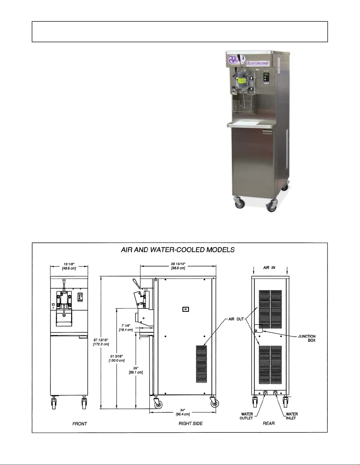
Figure 1-1 Model SU412 Machine
Figure 1-2 Machine Dimensions
1
Page 10
1.2 SPECIFICATIONS
Dimensions Machine with crate
width 19-1/8’’ (48,6 cm) 27’’ (68,6 cm)
height 67’’ (170,2 cm) 78’’ (198,1 cm)
depth 38-3/4’’ (98,4 cm) 48’’ (121,9 cm)
Weight 450 lbs (204,1 kg) 650 lbs (294,8 kg)
Electrical 1 Phase, 208-240 VAC, 60Hz
circuit ampacity
overcurrent protection
device
Compressor 11,000 Btu/hr Scroll™ Compressor
Drive Motor 3/4 hp
Air Flow Air cooled units require 3” (7,6 cm) air space on both sides, 6” back.
Plumbing Fittings
Hopper Volume 8 gallons (30,29 liters)
Freezing Cylinder
Volume
Model SU412
19A minimum
30A maximum
Water cooled units require 1/2” N.P.T. water and drain fi ttings. Maximum water
pressure of 130 psi. Minimum water fl ow rate of 3 GPM. Ideal EWT of 50°-70°F
2.1 gallon (7,95 liters)
Production Capacity 30 GPH (113,56 liters)
SU412
Refrigerant R-404A
Charge 32 oz
Suction Pressure
(at 72°F)
Discharge Pressure 210-235 psig
Cab Pressure
(only cab running)
EPR Valve 78-80 psig
18 psig (maintained by the bypass valve)
25-27 psig
Advanced On Time 28 seconds
* CutOut amps must be set on site.
Menu Display Value
Basic CutOut * amps
Cut In T 26.5 °F
Cycles 20 count
Stir On 15 seconds
Stir Off 300 seconds
Off Time 450 seconds
Stb Time 120 minutes
Sl1DrvOn 120 seconds
Sl1DrOff 180 seconds
Sl2CutIn 37 °F
Sl2CtOut 31 °F
DftOffTm 900 seconds
Storage Refriger 3 Cabinet
CabCutIn 38 °F
CabCtOut 34 °F
Cab Off 13 minutes
Cab On 130 seconds
U412 Confi gurations
Model Spinner Speed
U412 Standard -
TU412 Extra Thick -
SU412 Standard with Spinner 1600 rpm
STU412 Extra Thick with Spinner 2400 rpm
2
Page 11
1.3 MODES OF NORMAL OPERATION
Following are details of the operational modes on the U412.
NOTE:
The preset amounts, times, and temperatures
listed below are references to actual settings on
the IntelliTec control. Refer to Table 1-1 on page 6
for details on each setting.
A. INITIAL STATUS
When the Main Freezer Power and Freezing Cylinder
switches are placed in the ON position, the machine will
start in the “Sleep 1 Mode”. The display will read “Sleep
1 Mode”. The control will eventually move into the “Sleep
2” mode if the PUSH TO FREEZE button is not pressed.
When the PUSH TO FREEZE button is pressed the control
will move to the “Serve Mode”.
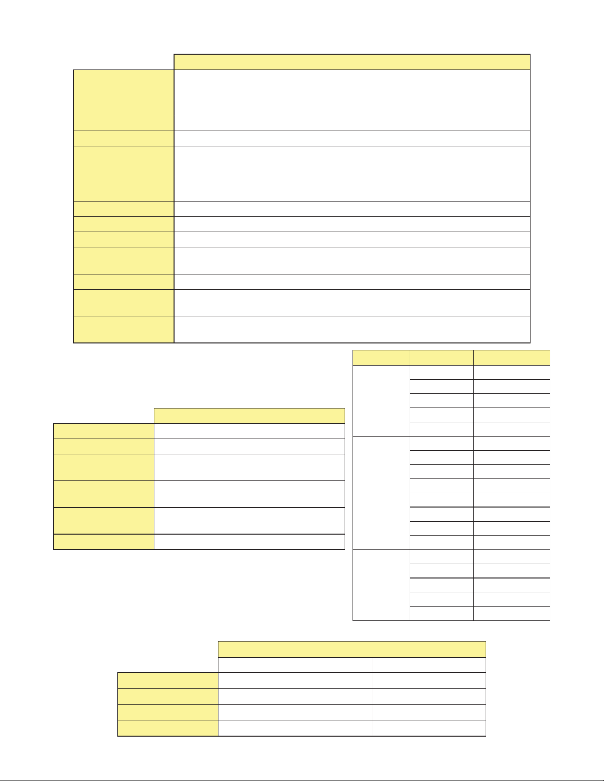
B. SERVE MODE
When the PUSH TO FREEZE button is pressed or a spigot
handle is pulled, the “Serve Mode” begins. The drive motor
starts, and after a 3 second delay, the compressor starts.
The display reads “FREEZING” on the top line and a bar
on the bottom line increases with product consistency.
A toroid on the IntelliTec control senses increasing drive
motor amperage as the product comes to consistency in
the freezing cylinder. When the control senses the product
is at 75% of consistency, the display will read “SERVE”,
the amber LED will go out and the green LED will blink.
At this time, product can be served from the machine.
The drive motor and compressor will continue to run until
the toroid reads a preset value (CutOut amps). When
the toroid reads the CutOut amps on the drive motor, the
compressor turns off. After a 3 second delay, the drive
motor turns off. The product in the freezing cylinder is now
at serving temperature and consistency and the green
LED will remain lit.
After product is at consistency, the IntelliTec control
continuously monitors refrigerant temperature through a
thermistor mounted on the side of the freezing cylinder.
When the temperature increases to a preset amount (Cut
In T), a 3-second drive motor pre-stir analyzes product
consistency. The pre-stir check is also performed each
time the spigot handle is opened. This check prevents
over-freezing of product, especially during frequent, small
volume draws. If product requires a freezing cycle, the
control will start the cycle.
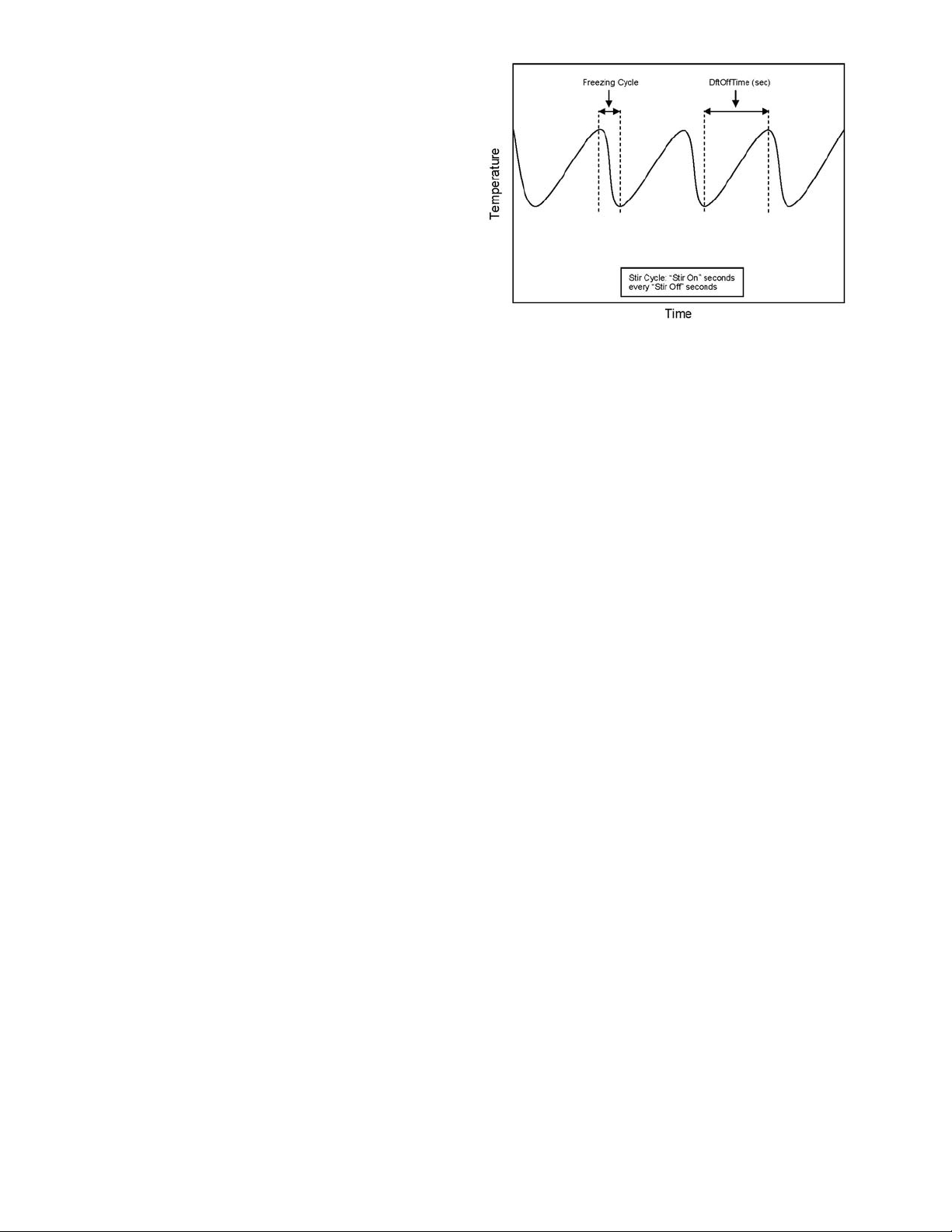
During the “Serve Mode”, a stir cycle starts. This cycle is
independent of the freezing cycle and is based on preset
times (Stir On and Stir Off). The stir cycle prevents product
separation. If a freezing cycle is initiated, the timer is reset.
In addition to the “Serve Mode” freezing cycle, there is a
freezing cycle based on a preset time (DftOffTime). If this
time is attained without a freezing cycle, the control will
automatically start a freezing cycle. If a freezing cycle is
initiated, the timer is reset.
Figure 1-3 Serve Mode
The machine will remain in “Serve Mode” until the cycle
count setting is attained. The cycle count is the number
of active freezing cycles and is based on a preset value
(Cycles). Once the cycle count has been reached without
user interruption, the control will move into the “Standby
Mode”.
If the PUSH TO FREEZE button is pressed or a spigot
handle is pulled, the cycle count is reset and the control
will move to the beginning of the “Serve Mode”. Refer to
Figure 1-3 for a graphical representation of the “Serve
Mode”.
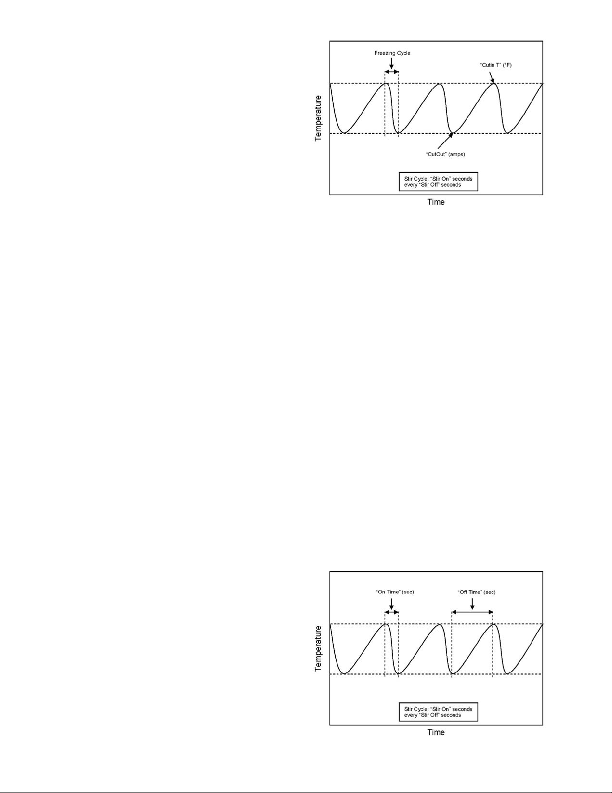
C. STANDBY MODE
If product has not been drawn from the spigot and the
preset number of active freezing cycles is met, the control
moves into the “Standby Mode”. In “Standby Mode”, the
freezing cycle is based on preset timers (On Time and Off
Time), and prevents ice crystals from building up in the
product. Because the product remains partially frozen,
it can quickly return to servable consistency when the
PUSH TO FREEZE button is pressed.
During “Standby Mode”, the stir cycle runs. This cycle is
based on preset, timed intervals (Stir On and Stir Off) and
prevents product separation.
Figure 1-4 Standby Mode
3
Page 12
The “Standby Mode” maintains product quality during
slow times, while minimizing reactivation time. This mode
lasts for a preset time (Stb Time). Once this time has been
reached without user interruption, the control moves into
the “Sleep 1 Mode”. Refer to Figure 1-4 for a graphical
representation of the “Standby Mode”.
If a spigot is opened or the PUSH TO FREEZE button is
pressed, the control will move to “Serve Mode”. Product
in the front of the freezing cylinders may or may not be at
consistency. The state of the product is dependent on a
number of variables but will come to consistency quickly.
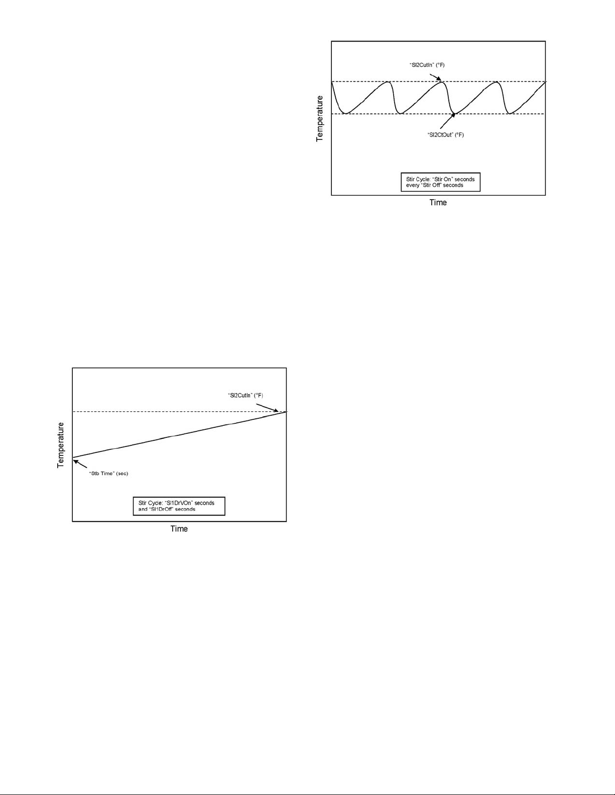
D. SLEEP 1 MODE
After the “Standby Mode” time has expired without user
interruption, the control will move into the “Sleep 1 Mode”.
During the “Sleep 1 Mode”, the stir cycle is handled by
preset timers (Sl1DrvOn and Sl1DrOff), and allows product
to melt to a liquid state by using agitation cycles without
any fl ow of refrigerant. Although the product temperature
never increases above 41°F, the product thaws rapidly
which minimizes product breakdown. The control will stay
in the “Sleep 1 Mode” until sensing a preset temperature
(Sl2CutIn). When this temperature has been reached without user interruption, the control will move to the “Sleep 2
Mode”. Refer to Figure 1-5 for a graphical representation
of the “Sleep 1 Mode”.
Figure 1-5 Sleep 1 Mode
If a spigot is opened or the PUSH TO FREEZE button is
pressed, the control will move to “Serve Mode”. If the spigot
is opened in “Sleep 1 Mode”, the product will not be at
consistency. The operator must wait until the fi rst “Serve
Mode” freezing cycle has completed to serve product.
E. SLEEP 2 MODE
The “Sleep 2 Mode” maintains the freezing cylinder
temperature between two preset values (Sl2CutIn and
Sl2CtOut). During the “Sleep 2 Mode”, the stir cycle
runs. This cycle is based on preset, timed intervals (Stir
On and Stir Off) and prevents product separation. The
“Sleep 2 Mode” is often referred to by customers as the
“night mode” and the machine will stay in this mode until
a spigot is opened or the PUSH TO FREEZE button is
Figure 1-6 Sleep 2 Mode
pressed. When this occurs, the control will move to “Serve
Mode”. If the spigot is opened at this time, the product
will be liquid. The operator must wait until the fi rst “Serve
Mode” freezing cycle has completed to serve product.
Refer to Figure 1-6 for a graphical representation of the
“Sleep 2 Mode”.
F. INTELLITEC RESTART
If a hard error occurs (refer the hard error list below), the
IntelliTec control will wait 5 minutes then attempt to clear
the error by restarting itself. The control will count each
restart attempt. The restart count will reset if the PUSH
TO FREEZE button is pressed, the spigot is pulled, or
the Freezing Cylinder OFF/ON switch is placed in the
OFF position.
The following are considered hard errors:
ERROR CODE MALFUNCTION
2 High Torque
3 Run Time
4 Clean
7 Drive Motor
9 High Pressure Cutout
When a restart occurs, the second line of the display will
read “Restart” and the backlight will blink. This will occur
regardless of the system mode.
G. SLEEP 3 MODE
If a high torque, run time, or drive motor error condition
occurs on the third restart attempt, the control will move
to the “Sleep 3 Mode”.
In “Sleep 3 Mode” freezing cylinder refrigeration will run
for 4 seconds every 10 minutes. This ensures the product
temperature never increases above 40°F. The stir cycle
and the auger do not run during “Sleep 3 Mode”.
The control will exit “Sleep 3 Mode” if the PUSH TO
FREEZE button is pressed, the spigot is pulled, or the
Freezing Cylinder OFF/ON switch is placed in the OFF
position.
4
Page 13
H. CLEAN MODE
When the CLEAN button is pressed, freezing cylinder
refrigeration stops, the drive motor starts and will run for
20 minutes and a 5 minute countdown timer is displayed.
After the time has elapsed, an optional audible alarm will
sound if this accessory has been installed. The audible
alarm is a reminder for the operator to end the “Clean
Mode” when cleaning is completed.
If the machine is kept in “Clean Mode” for more than 20
minutes, the auger drive motor stops, and an error code
(E4) is displayed on the display panel. The error code
prevents damage to the machine that could occur during
an extended clean mode (Refer to Section 8 - Troubleshooting for details). To clear this error, place the Freezing Cylinder Off-On switch in the Off position and back
in the On position. If the machine is still being cleaned,
pushing the CLEAN button will reset the timer and restart
the “Clean Mode”.
1.4 MIX LEVEL INDICATORS
The cabinet is equipped with a capacitive sensor to monitor mix level. When the mix level drops below the sensor
limit, the lower line of the display will read “Low Mix” and
the display will fl ash. To clear the “Low Mix” error, add
mix to the cabinet’s mix container.
1.5 STORAGE REFRIGERATION
The IntelliTec control is programmed to handle refrigeration
of the cabinet independently from the freezing cylinder.
The control maintains cabinet temperature between two
preset values (CabCutIn and CabCtOut). The cabinet
will operate automatically unless one of the following
conditions are met:
If the Main Power switch is in the OFF position
the Cab Off light on the front of the machine will
fl ash.
If the cabinet door is opened during a refrigeration
cycle, the evaporator fan will continue to run but
the refrigeration cycle will be interrupted to prevent
the evaporator coils from icing up.
If there is a High Pressure Cutout Error (E9) all
the refrigeration stops.
NOTE
If the temperature in the cabinet stays above 50°F
for more than two hours, the machine will go into
Sleep Mode and a clean message will be shown
on the display.
1.6 OPERATION DURING SENSOR FAILURE
The IntelliTec control is designed to allow the machine to
continue to function if a temperature sensor failure occurs. If a sensor fails, the display will show the error and
the control will run the machine on timers for the freezing
cycle or cabinet refrigeration. This allows the operator to
continue to serve product from the machine until proper
servicing can be completed.
Figure 1-7 Serve Mode (Sensor Failure)
A. SERVE AND STANDBY MODE
In the event of a temperature sensor failure on a freezing
cylinder, the IntelliTec control will function in two modes,
“Serve Mode” and “Standby Mode”. When the product is
at consistency in “Serve Mode”, the IntelliTec control uses
a timer instead of the sensor and will not start another
freezing cycle until a preset value (DftOffTm) is met.
The control will monitor product after it is at consistency,
activating the stir cycle and counting the number of cycles.
When the cycle count is reached, the control will move
to “Standby Mode”.
The “Standby Mode” is the same as in normal operation
with the exception of when the preset time (Stb Time) is
met, the control moves back into the “Serve Mode”. Refer
to Figure 1-7 for details.
B. CABINET REFRIGERATION
In the event of a temperature sensor failure in the cabinet, the cabinet refrigeration cycle is managed by preset
times (Cab On and Cab Off). This refrigeration cycle is
independent of the freezing cylinder refrigeration and the
cycle restarts if the cabinet door is opened.
1.7 MOTOR PROFILE CUTOUT
COMPENSATION
The IntelliTec control is programmed to automatically
function at a range of supply voltages. This feature provides the advantage of having product maintained at a
specifi c temperature and consistency irrespective of the
supply voltage. A motor profi le curve is programmed on
the IntelliTec control and provides a relationship between
the supply voltage and drive motor cutout amperage. Depending on the supply voltage, the control varies cutout
amperage according to the motor profi le. This feature is
automatic and does not need any confi guring.
5
Page 14
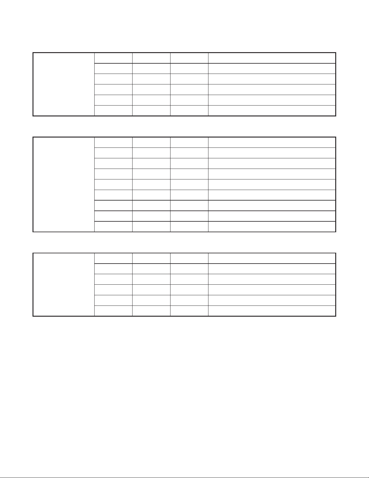
IntellITec Control Setting Specifi cations
Basic Menu DISPLAY Value MODE DEFINITION
CutOut * Serve Amp draw setting for cut out
Cut In T 26.5°F Serve Temperature setting for cut in
Cycles 20 Serve Freezing cycles before going into Standby Mode
Stir On 15 sec Serve Stir-only on time
Stir Off 300 sec Serve Stir-only off time
Advanced Menu DISPLAY Value MODE DEFINITION
On Time 28 sec Standby Freezing cycle “on” time (runs on timers only)
Off Time 450 sec Standby Freezing cycle “off” time
Stb Time 120 sec Standby Total time in mode
Sl1DrvOn 120 sec Sleep 1 Drive motor “on” timer
Sl1DrOff 180 sec Sleep 1 Drive motor “off” timer
Sl2CutIn 37°F Sleep 2 Cut in temperature
Sl2CtOut 31°F Sleep 2 Cut out temperature
DftOffTm 900 sec No Sensor Default “off” time. Used in case of sensor failure
Storage Menu DISPLAY Value MODE DEFINITION
Refriger Cabinet All Set to None, 1 Hopper, 2 Hopper, or Cabinet
CabCutIn 38°F All Refrigerated cab cut in temperature
CabCtOut 34°F All Refrigerated cab cut out temperature
Cab Off 13 sec No Sensor Default “off” time. Used in case of sensor failure
Cab On 130 sec No Sensor Default “on” time. Used in case of sensor failure
* The CutOut value needs to be adjusted to product requirements. Refer to the 2183775 - Specifi cation Sheet for SU412
Control located in the plastic pouch behind the header panel.
Table 1-1 IntelliTec Control Setting Specifi cations
6
Page 15
SECTION 2
INSTALLATION INSTRUCTIONS
2.1 SAFETY PRECAUTIONS
Do not attempt to operate the machine until the safety
precautions and operating instructions in this manual are
read completely and are thoroughly understood.
Take notice of all warning labels on the machine. The labels have been put there to help maintain a safe working
environment. The labels have been designed to withstand
washing and cleaning. All labels must remain legible for
the life of the machine. Labels should be checked periodically to be sure they can be recognized as warning labels.
If danger, warning or caution labels are needed, indicate
the part number, type of label, location of label, and quantity
required along with your address and mail to:
STOELTING, INC.
ATTENTION: Customer Service
502 Hwy. 67
Kiel, Wisconsin 53042
2.2 SHIPMENT AND TRANSIT
The machine has been assembled, operated and inspected
at the factory. Upon arrival at the fi nal destination, the
entire machine must be checked for any damage which
may have occurred during transit.
With the method of packaging used, the machine should
arrive in excellent condition. THE CARRIER IS RESPONSIBLE FOR ALL DAMAGE IN TRANSIT, WHETHER
VISIBLE OR CONCEALED. Do not pay the freight bill
until the machine has been checked for damage. Have
the carrier note any visible damage on the freight bill. If
concealed damage and/or shortage is found later, advise
the carrier within 10 days and request inspection. The
customer must place a claim for damages and/or shortages in shipment with the carrier. Stoelting, Inc. cannot
make any claims against the carrier.
2.3 MACHINE INSTALLATION
WARNING
Installation must be completed by a qualifi ed
electrician/refrigeration specialist.
Incorrect installation may cause personal injury,
severe damage to the machine and will void factory warranty.
A. Uncrate the machine.
B. Install the four casters. Turn the threaded end
into the machine until no threads are showing. To
level, turn out casters no more than 1/4” maximum,
then tighten all jam nuts.
C. The machine must be placed in a solid level
position.
NOTE
Accurate leveling is necessary for correct drainage
of freezing cylinder and to insure correct overrun.
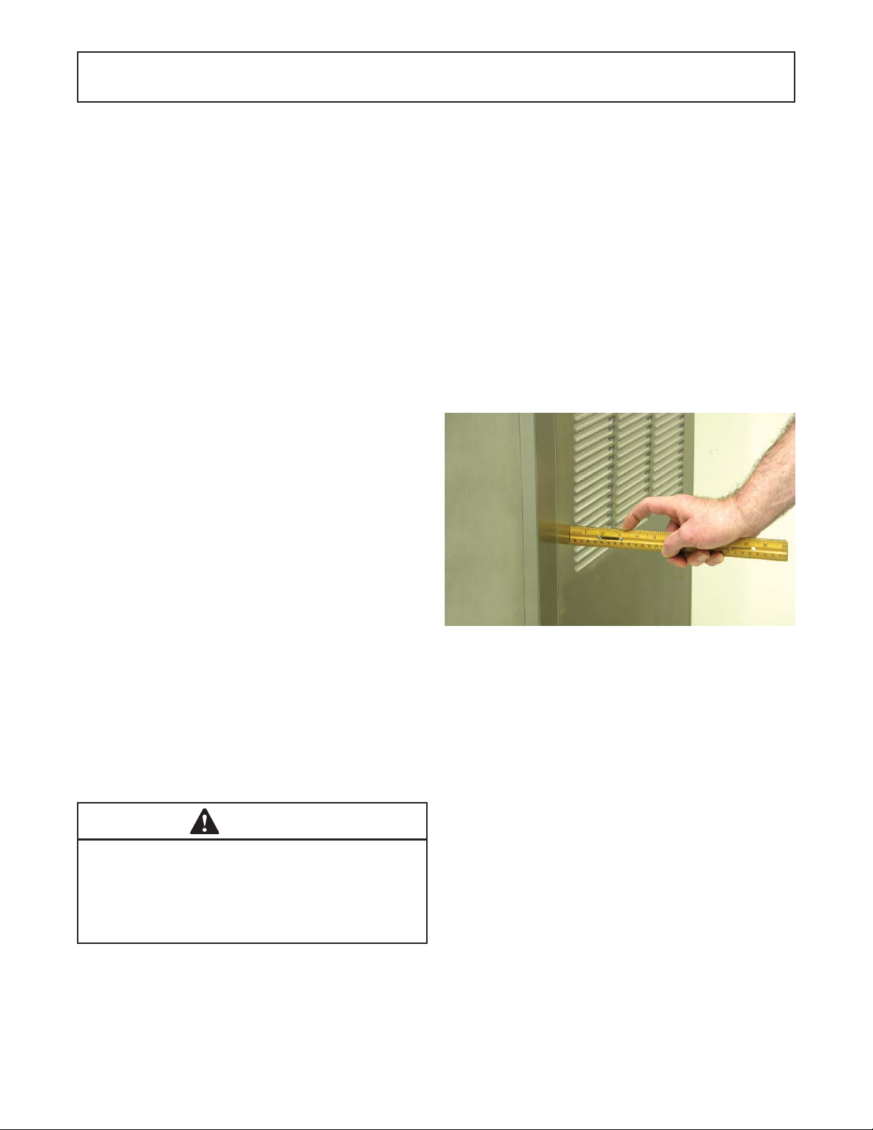
D. Machines with air cooled condensers require a
minimum of 3” (7,5cm) of space on all sides and
10” (25cm) at the top for proper circulation. (Fig.
2-1)
Figure 2-1 Space and Ventilation Requirements
E. Machines that have a water cooled condenser
require 1/2” NPT supply and drain fi ttings.
2.4 INSTALLING PERMANENT WIRING
To install wiring follow the steps below:
A. Refer to the nameplate on the side panel of the
machine for specifi c electrical requirements. Make
sure the power source in the building matches
the nameplate requirements.
B. Remove the back panel and the junction box
cover located at the bottom of the machine.
C. Install permanent wiring according to local code.
Installation of the machine involves moving the machine
close to its permanent location, removing all crating, setting in place, assembling parts, and cleaning.
7
Page 16
6” (15cm)
Figure 2-2 Mix Hose Installation
2.5 MIX PUMP
A. MIX PUMP HOSE INSTALLATION
Follow the steps below to install the mix pump hose in
the cabinet part of the machine.
1. Turn the mix pump on. The switch is located at
the top of the cabinet.
2. Feed one end of the mix pump hose into the
entering or pickup hose side (left) of black cover
(Fig 2-2).
NOTE
Feed the tube into the clamp so the natural curve of
the tube is towards the outside of the black cover.
This prevents the hose from looping around the
black cover twice.
3. Gently push the hose into the black cover until it
begins to feed.
4. Allow the hose to feed itself through the pump
until about 6” (15cm) remains on the entering
side.
5. Turn the pump off.
6. Connect the mix pump hose to the elbow fi tting
(located on the left side of the mix line manifold)
using a small hose clamp. Be careful not to twist
the mix hose.
7. Turn the pump on.
8. Allow the remaining 6” (15cm) of tubing to feed
through pump until the hose adapter prevents
further feeding.
9. Turn the pump off.
CAUTION
Risk of Product Damage
Air/Mix Tee must remain below the black cover
clamp. If the Tee is above the pump, mix may drain
into the air compressor resulting in pump damage.
10. Connect the free end of the mix pump hose to
the 3-way Tee (Fig. 2-3). When all connections
are complete, the 3-way Tee must be lower than
the black pump housing.
B. MIX PICKUP HOSE INSTALLATION
The U412 machine may be connected to the standard mix
container or up to three prepacked mix bags. Follow the
instructions below that match your confi guration.
Standard Connection:
1. Connect a 2” (5cm) length of 3/8” (9,5mm) ID
plastic food grade tubing to the mix pickup
assembly. Secure with hose clamps. Place the
assembly through the hole in the cover and install
the retaining clip.
8
Page 17
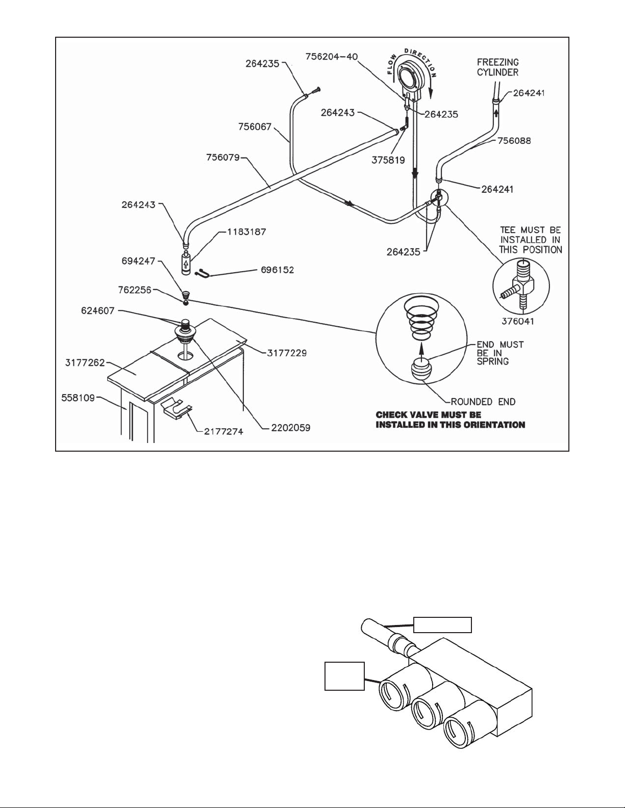
Figure 2-3 Mix Pump Connections for Standard Mix Container
2. Connect the free end of the tubing to the mix check
valve. Observe the direction of the check valve
fl ow arrow. Secure with a hose clamp. Connect a
24” (61cm) length of 3/8” (9,5mm) ID plastic food
grade tubing to the free end of the check valve
and secure with a hose clamp.
3. Connect the elbow fi tting to the free end of the
tubing. Connect the opposite end of the elbow
to 1/4” ID tan tubing on the left side of the pump
head. Secure with hose clamps (Fig. 2-3).
When Using Bag Connection System (BCS) with Three
Bags (optional kit):
The position of the three bags in the mix container is
important. The bag that is connected nearest the outlet
of the manifold will drain last and should be placed at
the back of the mix container. The mix low level indicator
relies on proper bag placement.
1. Connect 3/8” (9,5mm) ID plastic food grade tubing
to a bag adapter. Secure with hose clamps.
2. Slide the hose clip over free end of 3/8” (9,5mm)
ID plastic food grade tubing. Attach the free end
of the tubing to a manifold adapter. Secure with
a large hose clamp or equivalent.
3. Push the manifold adapter with spring and valve
into the left port (nearest the manifold outlet) of
the mix inlet manifold and secure with a retaining
clip. (Fig. 2-5).
Mix Outlet
Drains
Last
Figure 2-4 BCS Mix Inlet Manifold
9
Page 18
4. Repeat steps 1 to 3 for the middle port and for
the right port of the mix inlet manifold.
5. Place three mix bags into the mix container.
6. Connect the bag adapter attached to the left side
of the manifold (closest to the mix outlet) to the
mix bag in the back of the mix container.
7. Connect the bag adapter attached to the middle
of the manifold to the mix bag in the middle of
the mix container.
8. Connect the bag adapter attached to the right
side of the manifold (farthest from the mix outlet)
to the mix bag in the front of the mix container.
When Using Bag Connection System (BCS) with One
or Two Bags (optional kit):
When connecting one or two bags, the manifold adapters must be installed closest to the manifold outlet and
the manifold plug(s) must be placed farthest from the
manifold outlet.
1. Connect 3/8” (9,5mm) ID
plastic food grade tubing
to a bag adapter. Secure
with hose clamps.
2. Slide the hose clip
over the free end of
the tubing. Attach the
free end of the tubing
to a manifold adapter.
Secure with a large hose
clamp.
3. Push the manifold
adapter with spring and
valve into the left port
(nearest the manifold
outlet) of the mix inlet
manifold and secure
with retaining clip. (See
Figure 2-5).
4. If using two mix bags,
repeat steps 1 to 3 for
the middle port.
5. Install a manifold plug
into each empty inlet and
secure with a retaining
clip.
6. Place the mix bag(s) into
the mix container.
7. Connect the bag adapter
attached to the left side
of the manifold (closest
to the mix outlet) to the
mix bag in the back of
the mix container.
Manifold
Adapter
C. MIX LOW LEVEL INDICATOR ADJUSTMENT
The sensitivity of the “Mix Low” indication that displays on
the control panel can be adjusted to operator preference.
If more advanced notice of low mix is required, loosen the
black adjustment knobs located on the sensor brackets
at the back of the machine cabinet and slide the bracket
upwards. If the “Mix Low” message appears while there
is still suffi cient mix in the container, slide the bracket
downward. Be sure to tighten the adjustment knobs after
properly positioning the sensor.
Mix Inlet
Retaining
Clip
Manifold
Plug
Bag Adapter
Manifold
Figure 2-5 Bag Connection System (Optional)
10
Page 19
SECTION 3
INITIAL SET-UP AND OPERATION
3.1 OPERATOR’S SAFETY PRECAUTIONS
SAFE OPERATION IS NO ACCIDENT; observe these
rules:
A. Know the machine. Read and understand the
Operating Instructions.
B. Notice all warning labels on the machine.
C. Wear proper clothing. Avoid loose fi tting garments,
and remove watches, rings or jewelry that could
cause a serious accident.
D. Maintain a clean work area. Avoid accidents by
cleaning up the area and keeping it clean.
E. Stay alert at all times. Know which switch, push
button or control you are about to use and what
effect it is going to have.
F. Disconnect power for maintenance. Never
attempt to repair or perform maintenance on the
machine until the main electrical power has been
disconnected.
G. Do not operate under unsafe operating conditions.
Never operate the machine if unusual or excessive
noise or vibration occurs.
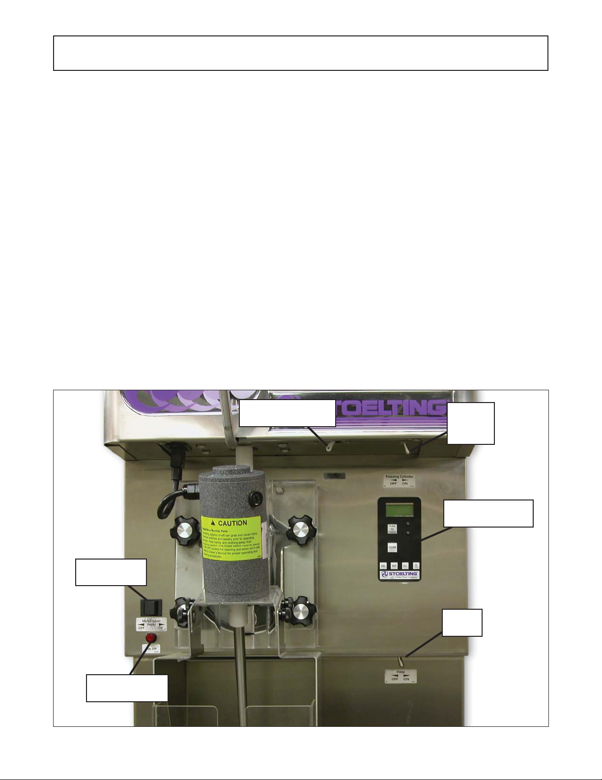
3.2 OPERATING CONTROLS AND INDICATORS
Before operating the machine, it is required that the operator know the function of each operating control. Refer
to Figure 3-1 for the location of the operating controls on
the machine. For the information regarding error codes
displayed on the control panel, refer to the troubleshooting
section of this manual.
A. MAIN FREEZER POWER SWITCH
The Main Freezer Power switch is a two position rocker
switch that supplies power to the IntelliTec control, freezing cylinder circuits lower cabinet refrigeration system.
When the switch is placed in the ON position, the cabinet
refrigeration system will run until the preset temperature
is reached; then it will cycle ON and OFF to maintain that
temperature. Power to the freezing cylinders can then be
controlled with the Freezing Cylinder OFF/ON switch.
B. FREEZING CYLINDER OFF/ON SWITCH
The Freezing Cylinder OFF/ON switch is a two position
toggle switch used to supply power to the freezing cylinder
control circuit. When the switch is in the OFF position,
the freezing cylinder’s refrigeration system and auger will
not operate. When the switch is in the ON position, the
machine will be operational.
Main Freezer
Power Off/On
Cab Off
Indicator Light
Blender Power Off/
On Circuit Breaker
Freezing
Cylinder
Off/On
IntelliTec Control
(See Figure 3-2)
Pump
Off/On
Figure 3-1 Machine Controls
11
Page 20

C. SPIGOT SWITCH
The spigot switch is mounted to the spigot cam assembly
behind the header panel. When the spigot is opened to
dispense product, the spigot switch opens and the “Serve
Mode” begins.
D. BLENDER POWER OFF/ON AND CIRCUIT BREAKER
SWITCH
The Blender Power Off/On and Circuit Breaker switch
is a two position toggle switch used to supply power to
the blender (SU412 models). When the switch is in the
OFF position, there is no power to the blender. When the
switch is in the ON position, the blender will operate any
time the spigot handle is pushed to the right. This switch
also serves as a circuit breaker to interrupt power if the
rotation of the blender agitator becomes hindered.
E. CAB OFF INDICATOR LIGHT
A fl ashing light indicates the Main Freezer Power Switch
is in the OFF position; no refrigeration is being supplied
to the cab. Place the Main Freezer Power switch in the
ON position for cab refrigeration.
F. PUMP SWITCH
The pump motor switch is the toggle switch located on
the front of the machine. When the switch is placed in
the OFF position, the pump will not run. When the switch
is placed in the ON position, the pump will run until the
preset pressure is reached. It then cycles on and off as
product is drawn to maintain that pressure.
G. PUSH TO FREEZE BUTTON
The PUSH TO FREEZE button is a membrane or snap
switch used to initiate “Serve Mode”.
NOTE
After the PUSH TO FREEZE button is pressed,
the drive motor starts. After a 3-second delay, the
compressor will start.
H. LEDS
The membrane switch (touchpad) features two lights: a
green LED and an amber LED. The green LED is lit during “Serve Mode”. During freeze down, it is not lit. When
product consistency approaches 90% in the freezing
cylinder, the green LED fl ashes. The amber LED is on
during all other modes. Both LEDs alternatively fl ash if
an error occurs or if the freezing cylinder is off.
I. CLEAN BUTTON
The CLEAN button is a membrane, or snap switch. When
the button is pressed, the freezing cycle stops and the
drive motor will start. A CLEAN message will display on
the LCD screen along with a 5-minute countdown timer.
If the button is pressed again, the timer will reset. To
exit the CLEAN mode, turn the Freezing Cylinder OFF/
ON switch to the OFF position. If the machine is left in
CLEAN for more than 20 minutes, an error code (E4) will
be displayed on the display panel. Place the Freezing
Cylinder OFF/ON switch in the OFF position and back in
the ON position to clear this error.
J. DRIVE MOTOR OVERLOAD
The internal drive motor overload will trip if the drive
motor is overloaded. It will reset after approximately 1012 minutes. If the drive motor continues to trip, refer to
Troubleshooting in Section 5.
K. MIX LOW LIGHT INDICATOR
A MIX LOW message will appear on the LCD display to
alert the operator of a low mix condition. The message
will display when there is approximately one gallon of
mix left in the mix container or when one bag of the Bag
Connection System (BCS) is empty. When the MIX LOW
message is displayed, refi ll the container or replace a
bag immediately.
L. MENU NAVIGATION BUTTONS
The Menu Navigation Buttons allow the user to display
information regarding the machine’s status of operation
as well as adjust product consistency (Fig. 3-2).
Selection Button (SEL) The SEL button is used in
combination with the left arrow button to enter into
the settings of the IntelliTec control. This button is
also used to navigate through the control settings
menu.
Set Button (SET) The SET button is used to save
a change made to the product consistency setting.
It is also used to save changes when modifying
control settings.
Left Arrow Button () If the left arrow button is
pressed for 5 seconds, the display will remain lit.
To turn the light off, press the left arrow button for
5 seconds. The left arrow button is used primarily
to navigate through the control settings.
Up Arrow Button () After pressing the SET
button, the up arrow button will change the value
of the product consistency setting. This button
is used primarily to navigate through the control
settings.
Push to Freeze
Green LED
Amber LED
Purge/Clean
Button
SEL Button
SET Button
Left Arrow Button
Up Arrow Button
Figure 3-2 IntelliTec Control
12
Page 21
3.3 DISASSEMBLY OF MACHINE PARTS
WARNING
Moving machinery can grab, mangle and dismember. Place the Main Freezer Power Off/On switch in
the OFF position before disassembling for cleaning
or servicing.
Before using the machine for the fi rst time, complete
machine disassembly, cleaning and sanitizing procedures need to be followed. Routine cleaning intervals
and procedures must comply with the local and state
health codes. Inspection for worn or broken parts should
be made at every disassembly of the machine. All worn
or broken parts should be replaced to ensure safety to
both the operator and the customer and to maintain good
machine performance and a quality product.
To disassemble the machine, refer to the following steps:
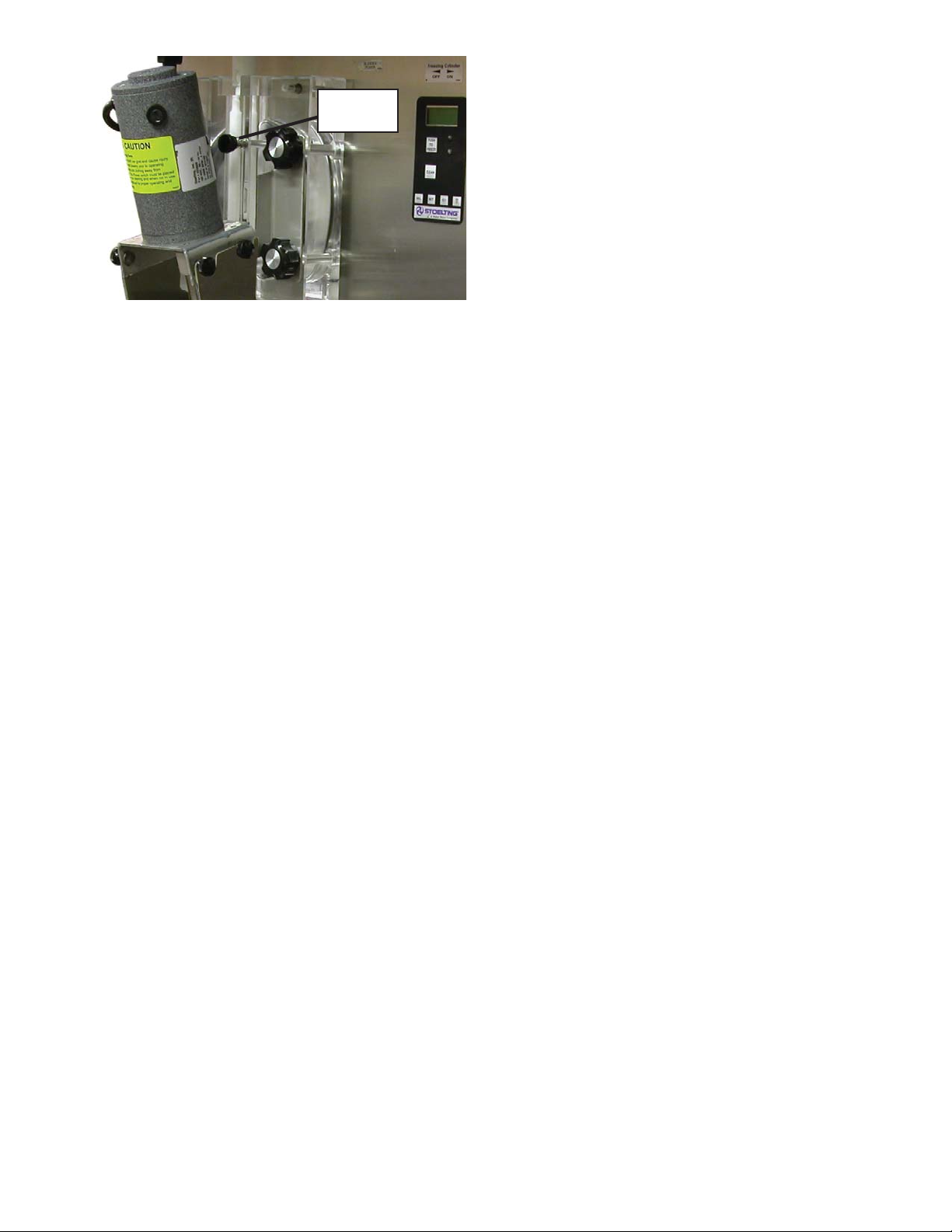
A. REMOVE BLENDER (SU412 MODELS)
1. Turn the Main Freezer Power Off/On switch to
the OFF position.
2. Unplug the blender.
3. Remove the blender agitator by holding the blender
shaft and turning the agitator counterclockwise.
4. Loosen knobs holding the blender splash shield
bracket in place and remove the bracket (Fig.
3-3).
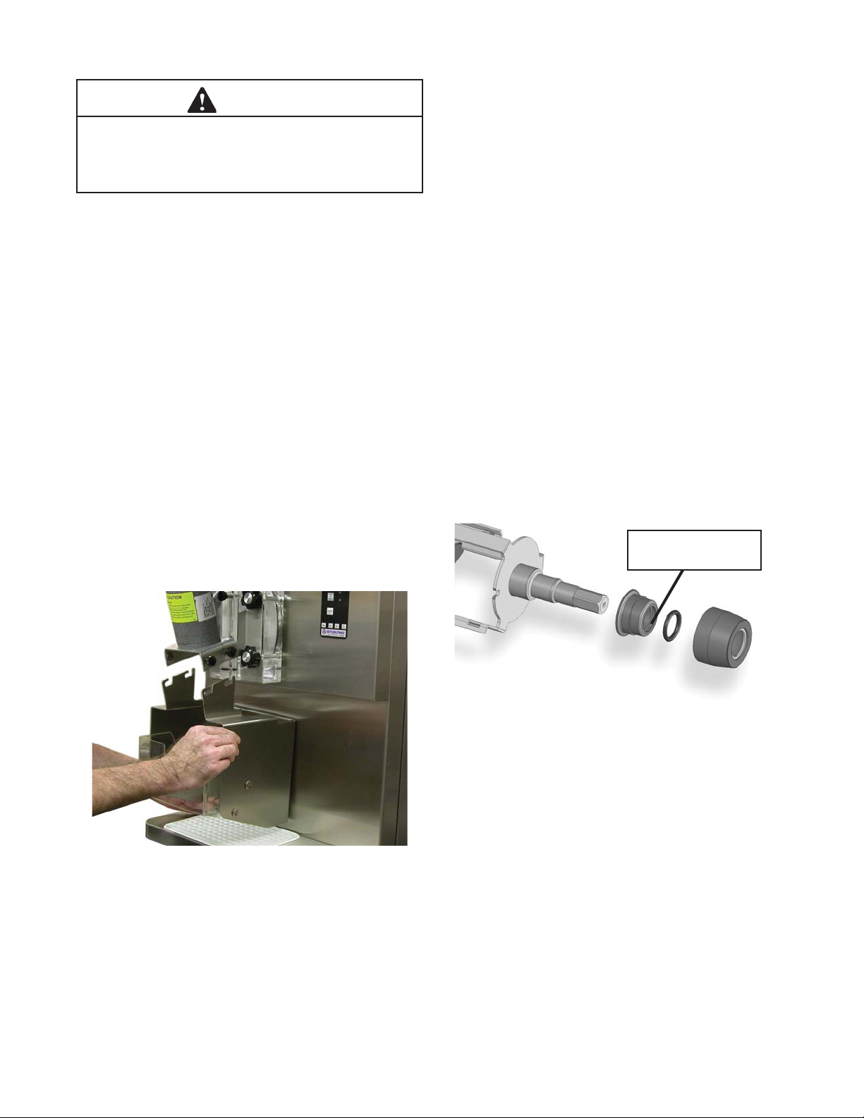
B. REMOVE FRONT DOOR AND AUGER
1. Make sure the Main Freezer Power Off/On switch
is in the OFF position
2. Remove the knobs on the front door and remove
the door by pulling it off the studs.
3. Remove the air bleed valve by unscrewing the
knob while holding the valve stem from behind.
Remove the compression spring and push the
air bleed valve through the rear of the front door.
4. Remove the spigot through the bottom of the front
door. Remove all o-rings from the spigot and the
air bleed valve.
5. Remove the plastic bearing from the front auger
support. The plastic bearing may be on the front
door.
6. Remove the auger by pulling slowly. Be careful
not to scratch the inside of the freezing cylinder
when removing the auger.
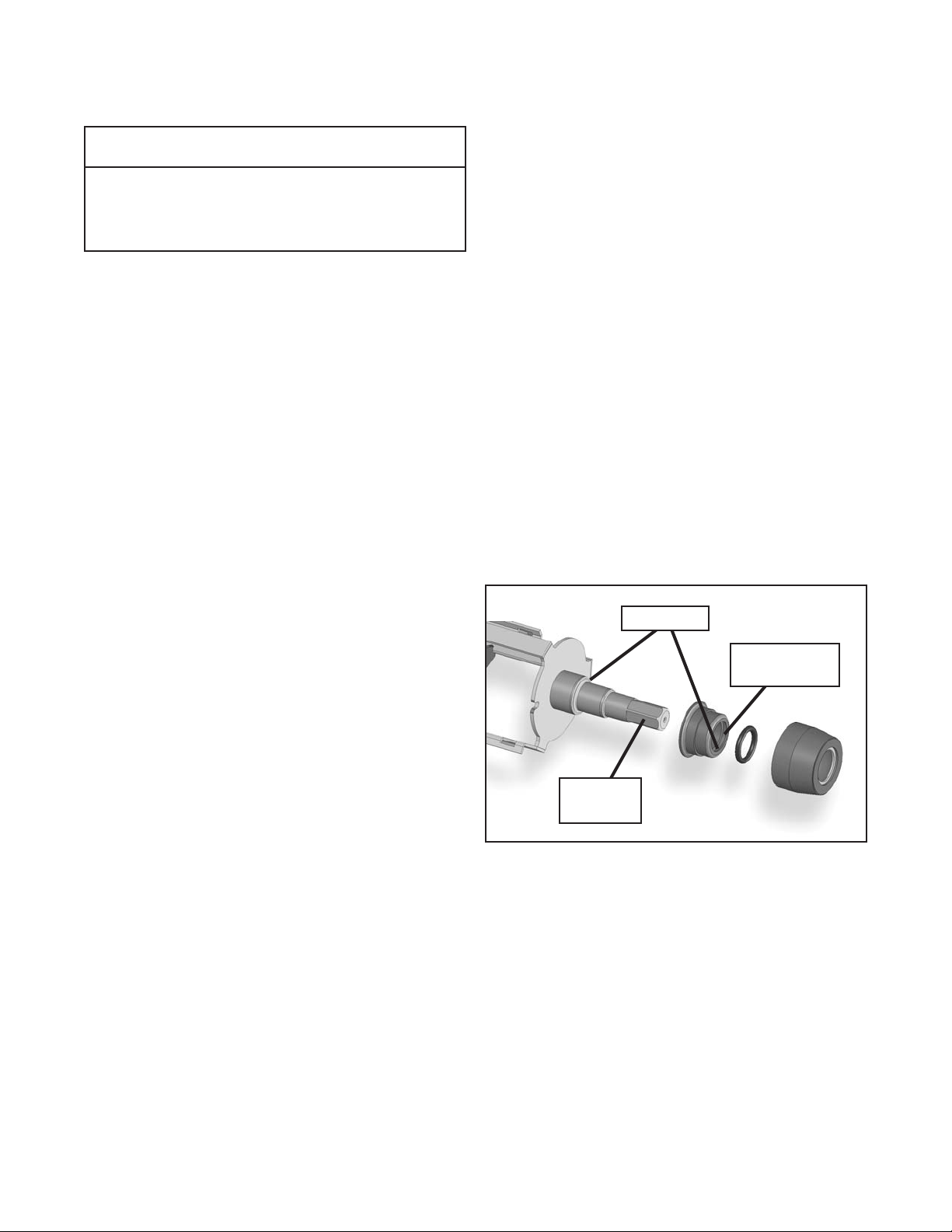
7. Keep the rear of the auger tipped up once it is
clear of the freezing cylinder to prevent the rear
seal assembly from dropping.
8. Wipe the spline lubricant off of the hex end of the
auger with a paper towel. Remove the rear seal
assembly (Fig. 3-4).
Remove O-Ring
From Inside Insert
Figure 3-3 Removing Splash Shield Bracket
5. Remove the knobs on the front door. Remove
the blender assembly and set aside.
NOTE
Support the blender with one hand while removing
the knobs on the door to prevent the blender from
dropping.
Figure 3-4 Rear Seal Assembly
3.4 CLEANING DISASSEMBLED PARTS
Disassembled machine parts require complete cleaning,
sanitizing and air drying before assembling. Local and state
health codes will dictate the procedure required. Some
state health codes require a four sink process (pre-wash,
wash, rinse, sanitize, air dry), while others require a three
sink process (without the pre-wash step). The following
procedures are a general guideline only. Consult your
local and state health codes for the procedures required
in your location.
A. Disassemble all parts. (Refer to Section 3.4 for
the disassembly of machine parts.)
13
Page 22
B. Place all front door and auger parts in clean 90° to
110°F (32°C to 43°C) water and wash thoroughly
(four sink procedure only).
CAUTION
Blender motor can NOT be immersed in water or
sanitizer. Wash the motor and mounting bracket
with a mild detergent solution taking care not to
allow water into the motor bearings or seals.
C. Place all parts in 90° to 110°F (32°C to 43°C) mild
detergent water and wash thoroughly.
D. Rinse all parts with clean 90° to 110°F (32°C to
43°C) water.
E. Sanitize all machine parts following procedures
outlined below.
3.5 SANITIZING MACHINE PARTS
A. Use a sanitizer, mixed according to manufacturer’s
instructions, to provide a 100 parts per million
strength solution. Mix sanitizer in quantities of
no less than 2 gallons of 90° to 110°F (32°C to
43°C) water. Any sanitizer must be used only in
accordance with the manufacturer’s instructions.
B. Place all parts in the sanitizing solution for 5
minutes, then remove and let air dry completely
before assembling in machine.
3.7 ASSEMBLING MACHINE
To assemble the machine parts, refer to the following steps:
NOTICE
Petrol-Gel sanitary lubricant or equivalent must be
used when lubrication of machine parts is specifi ed.
NOTICE
The United States Department of Agriculture and
the Food and Drug Administration require that lubricants used on food processing equipment be certifi ed for this use. Use lubricants only in accordance
with the manufacturer’s instructions.
A. Assemble all o-rings onto parts dry, without
lubrication. Then apply a thin fi lm of sanitary
lubrication to exposed surfaces of the o-rings.
B. Lubricate the rear seal area on the auger shaft
with a thin layer of sanitary lubricant. Install the
rear seal o-ring. Lubricate the outside of the rear
seal o-ring with sanitary lubricant.
C. Install the stainless steel rear seal adapter into
the rear seal dry (without lubricant). Lubricate the
inside surface of the rear seal adapter, including
the adapter o-ring, and install it onto the auger
shaft. DO NOT lubricate the outside of the rear
auger seal (Fig. 3-5).
Petrol-Gel
3.6 CLEANING THE MACHINE
The exterior should be kept clean at all times to preserve
the luster of the stainless steel. A high grade of stainless
steel has been used on the machine to ease cleanup. To
remove spilled or dried mix, wash the exterior with 90° to
110°F (32°C to 43°C) soapy water and wipe dry.
Do not use highly abrasive materials, as they will mar the
fi nish. A mild alkaline cleaner is recommended. Use a soft
cloth or sponge to apply the cleaner. For best results, wipe
with the grain of the steel.
A. Clean the rear seal surface from inside of the
freezing cylinder.
B. Using sanitizing solution and the large barrel
brush provided, sanitize the freezing cylinder by
dipping the brush in the sanitizing solution and
brushing the inside of the freezing cylinder.
C. Remove the rear drip tray by pulling from the side
panel. Clean and replace the drip tray.
Place O-Ring
Inside Insert
Spline
Lubricant
Figure 3-5 Rear Seal Assembly
D. Lubricate the hex drive end of the auger with a
small amount of spline lubricant. A small container
of it is shipped with the machine.
E. Install the two plastic scraper blades onto the
auger and insert into the freezing cylinder.
F. Rotate the auger until it engages the drive shaft.
G. Assemble the air bleed valve o-ring onto the air
bleed valve. Position the o-ring into the groove
close to the wide part. Apply a thin fi lm of sanitary
lubricant to the o-ring.
14
Page 23
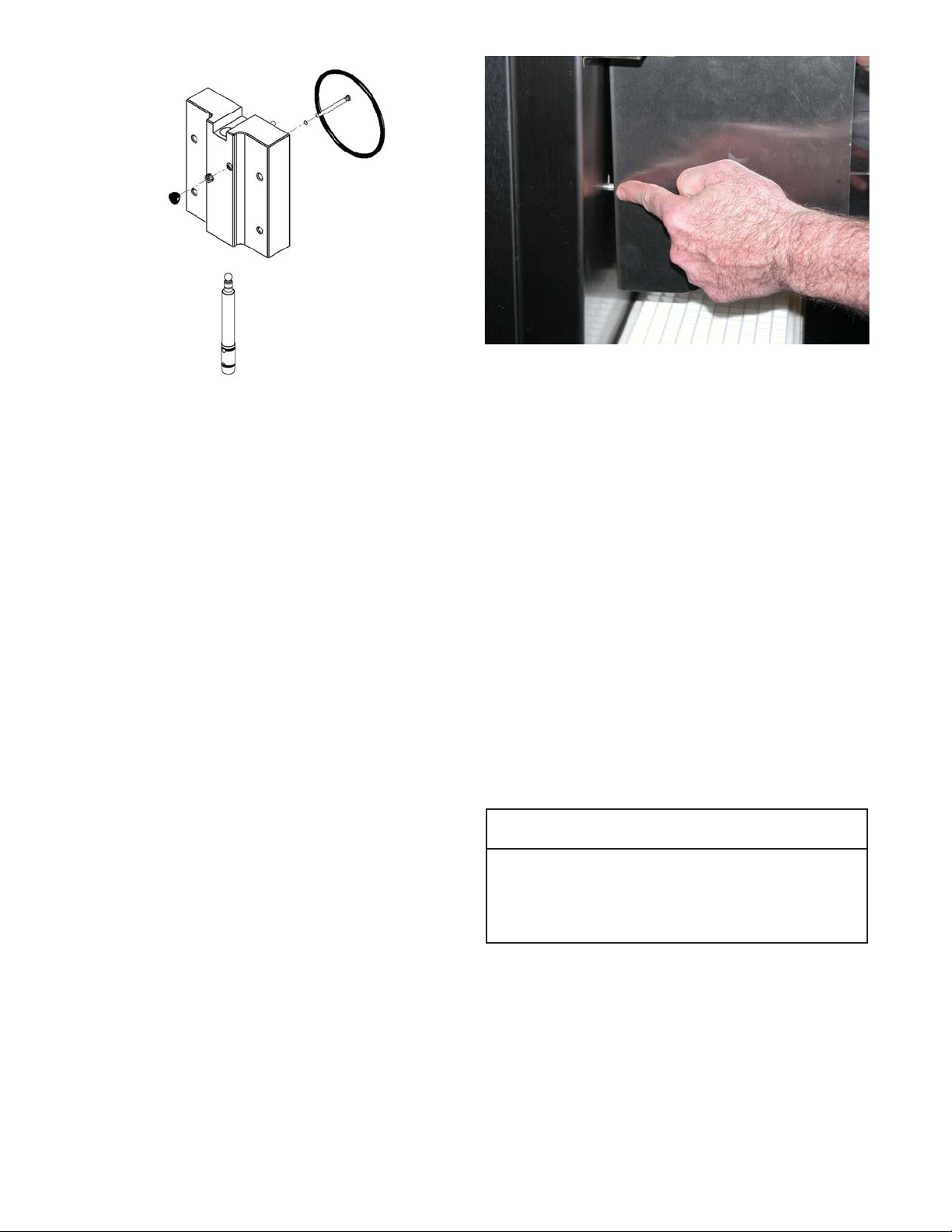
Figure 3-7 Blender Shroud Pin Alignment
Figure 3-6 Front Door Assembly
H. Insert the air bleed valve into the back of the front
door. Install the compression spring onto the air
bleed valve then screw the knob on fi nger tight.
I Install the spigot through the bottom of the front
door.
J. Apply a thin fi lm of sanitary lubricant to the door
seal o-ring, and fi t it into the groove on the rear
of the front door.
K. Apply a thin fi lm of sanitary lubricant to the inside
and outside of the front auger support bushing,
then place it into the front door.
L. Place the front door assembly on the mounting
studs and the push front door against the machine
carefully.
M. Place the blender assembly onto the front door
studs.
N. Secure the front door and the blender assembly
to the machine by placing the knobs on the studs
and alternately tightening opposite corners until
fi nger tight. Do not overtighten. Proper o-ring seal
can be observed through the transparent front
door.
O. On SU412 model, attach the blender shroud to
the blender assembly. The blender shroud has
a pin that needs to be properly aligned with the
machine safety switch (Fig. 3-7).
3.8 SANITIZING
Sanitizing must be done after the machine is clean and
just before the machine is fi lled with mix. Sanitizing the
night before is not effective. However, you should always
clean the machine and parts after using it.
NOTE
The United States Department of Agriculture and
the Food and Drug Administration require that all
cleaning and sanitizing solutions used with food
processing equipment be certifi ed for this use.
When sanitizing the machine, refer to local sanitary regulations for applicable codes and recommended sanitizing
products and procedures. The frequency of sanitizing
must comply with local health regulations. Mix sanitizer
according to manufacturer’s instructions to provide a 100
parts per million strength solution. Mix sanitizer in quantities of no less than 2 gallons of 90°F to 110°F (32°C to
43°C) water. Allow sanitizer to contact the surfaces to be
sanitized for 5 minutes. Any sanitizer must be used only
in accordance with the manufacturer’s instructions.
CAUTION
Risk of Product Damage
Avoid prolonged contact of sanitizer with machine
parts. Sanitizer may cause corrosion of stainless
steel parts if there is prolonged contact.
A. Prepare 3 gallons of sanitizing solution following
the manufacturer’s instructions. Pour it into a
clean container and place the container into the
cabinet.
15
Page 24
Air Bleed
Valve
Figure 3-8 Air Bleed Valve
B. Place the mix pump switch in the ON position
and open the air bleed valve on the front door
by pushing the valve in and holding (see Figure
3-8).
C. Let sanitizing solution fi ll the freezing cylinder to
the air bleed valve. Close the valve by pulling it
out to lock it into place.
D. Place the Main Power OFF/ON and Freezing
Cylinder OFF/ON switches in the ON position.
Press the CLEAN button.
E. Check for leaks when the freezing cylinder is fi rst
pressurized with sanitizing solution.
1. Check for leaks at the front door seals.
2. Check the drain tray located in the side panel
for leaks coming from the rear of the rear auger
seal.
3. Check the inside of the cab unit for leaks at
the hose connections.
F. Using a sanitized soft bristle brush (or equivalent)
dipped in sanitizing solution, clean the mix
container.
G. After fi ve minutes, open the spigot to expel
sanitizing solution. Drain all of the solution from
the machine.
H. When the solution has drained, press the CLEAN
button to stop the auger and place the Main Power
OFF/ON and Freezing Cylinder OFF/ON switches
in the OFF position. Allow the freezing cylinder
to drain completely.
I. On SU412 model, sanitize the agitator and shaft
with a cup of sanitizing solution.
The machine is now sanitized and ready for adding mix.
3.9 INITIAL FREEZE DOWN AND OPERATION
Every Stoelting soft serve machine needs to be set on site.
The following adjustment will provide optimal product
consistency while prolonging product life.
NOTE
The machine is designed for correct operation in
ambient temperatures between 50°F and 110°F.
T emperatures out of that range may cause refrigeration problems and product quality issues.
A. ADDING MIX
1. Sanitize the machine immediately before use.
2. Make sure the Freezing Cylinder OFF/ON switch
is in the OFF position.
3. Fill the mix container in the cab with at least 2.5
gallons of mix.
4. Attach the mix inlet probe to the container and
place the container in the refrigerated cab.
5. The mix pump switch is located at the front of the
machine. Place it in the ON position.
6. Place a container under the spigot and open the
spigot to allow the mix to fl ush out about 8 ounces
(0.23 liters) of sanitizing solution and liquid mix.
Close the spigot.
7. Open the air bleed valve on the front door by
pressing and holding. Hold the valve open until
the mix level in the freezing cylinder is 1/2” from
the air bleed valve.
B. PREPARING THE INTELLITEC CONTROL
8. On the IntelliTec control, press and hold the SEL
button for 8 seconds. While still holding the SEL
button, press the up arrow () button. The LCD
will read “DISPLAY”.
9. Press the left arrow () button once. The display
will read “BASIC”.
10. Press the up arrow () button once. The display
will read “CutOut amps”.
11. Press the SET button. A cursor will start blinking
under the far right digit.
12. Change the value to 8.0. Press the left arrow ()
button to move the cursor. Press the up arrow ()
button to increase the digit. When a digit reaches
9, pressing the up arrow () button again will
change the value to 0.
16
Page 25

13. After entering 8.0, press SET to save this value.
The LCD will read “CutOut Set -- OK”.
14. Press the SEL button. The LCD will read “CutOut
amps 8.0”.
15. Press the SEL button twice. The LCD will read
“DISPLAY”.
16. Press the up arrow () button to navigate to the
“°F” and “amps” readings.
C. INITIAL FREEZE DOWN
17. Place the Freezing Cylinder OFF/ON switch in
the ON position.
18. Press the PUSH TO FREEZE button.
NOTE
After the drive motor starts, there is a 3-second
delay before the compressor starts.
19. As the product freezes, the “amps” value on
the display will increase. When it reaches 2.8A,
open the spigot, take a 6-8 ounce sample and
measure the temperature. For most shake mixes,
the desired temperature is between 23.5°F and
24.0°F.
CAUTION
Do not exceed 3.5 amps with a 3/4 hp motor.
20. Draw samples at every increase of 0.2A until
reaching the desired consistency and temperature.
NOTE
Show the sample to the customer and make sure it
meets their required consistency and temperature.
21. Record the “amps” value.
22. Place the Freezing Cylinder OFF/ON switch in
the OFF position.
D. ADJUSTING THE INTELLITEC CONTROL
23. Press the SEL button. The display will read
“DISPLAY”.
24. Press the left arrow () button once. The display
will read “BASIC”.
25. Press the up arrow () button once. The display
will read “CutOut amps”.
26. Change the value to the recorded value by
pressing the SET button. A cursor will start blinking
under the far right digit.
27. Press the left arrow () button to move the cursor.
Press the up arrow () button to increase the digit.
When a digit reaches 9, pressing the up arrow
() button again will change the value to 0.
28. Press the SET button to save the value. The LCD
will read “CutOut Set -- OK”.
29. Press the SEL button. The LCD will read “CutOut
amps” along with the programmed value from the
previous step.
30. Press the SEL button three times. The LCD will
read “EXITMENU”.
31. Press the up arrow () button to exit the menu.
32. Adjustment to the control is completed.
E. SERVING PRODUCT
33. Place the Freezing Cylinder OFF/ON switch in
the ON position.
34. Press the PUSH TO FREEZE button.
35. When the product is at 75% consistency, the
display will read “SERVE”.
36. For normal dispensing, move the spigot handle
fully open.
37. The machine dispenses product at a reasonable
draw rate. If the machine is overdrawn, the result
is a soft product or a product that will not dispense
at all. If this occurs, allow the machine to run for
approximately 30 seconds before dispensing
more product.
38. Do not operate the machine when the MIX LOW
message is displayed. Refi ll the mix container
immediately.
NOTE
The machine has a standby and sleep mode. After
a preset number of freezing cycles, it will enter the
standby mode (followed by sleep mode) and remain
there until someone draws product or presses the
PUSH TO FREEZE button. In the sleep mode, the
machine will keep the product below 41°F (7.2°C).
Sleep modes do not take the place of cleaning
and sanitizing. Federal, State, and local regulatory
agencies determine frequency of cleaning and
sanitizing.
3.10 NORMAL FREEZE DOWN AND
OPERATION
The following section contains the recommended operating procedures for the safe operation of the machine.
A. Sanitize immediately before use.
B. Make sure the Freezing Cylinder Off/On switch
is in the OFF position.
C. Fill the storage containers in the cab with at least
2.5 gallons of mix.
D. Attach the mix inlet probes to the container and
place the containers in the refrigerated cab.
17
Page 26
E. Place the mix pump switch in the ON position.
F. Place a container under the spigot and open the
spigot to allow the mix to fl ush out about 8 ounces
(0.23 liters) of sanitizing solution and liquid mix.
Close the spigot.
G. Open the air bleed valve on the front door by
pressing and holding. Hold the valve open until
the mix level in the freezing cylinder is 1/2” from
the air bleed valve.
H. Place the Freezing Cylinder OFF/ON switch in
the ON position. Make sure the blender power
plug is connected to the machine and place the
Blender Power Off/On switch in the ON position.
WARNING
Hazardous Moving Parts
Blender shaft and agitator can grab and cause
injury. Do not operate blender without protective
shield or swing splash shield.
I. Press the PUSH TO FREEZE button.
NOTE
After the drive motor starts, there is a 3-second
delay before the compressor starts.
J. When the product is at 75% consistency, the
display will read “SERVE”.
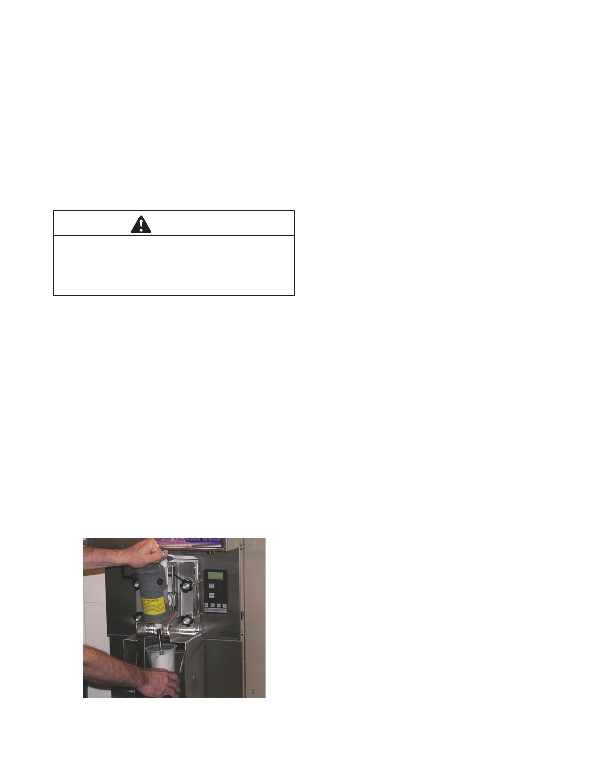
K. For normal dispensing, move the spigot handle
fully open (Fig. 3-9).
L. On SU412 model, push the spigot handle to the
right to activate the blender. The blender will
operate during or after dispensing product.
M. Do not operate the machine when the MIX LOW
message is displayed. Refi ll the mix container
immediately.
NOTE
The machine has a standby and sleep mode. After
a preset number of freezing cycles, it will enter the
standby mode (followed by sleep mode) and remain
there until someone draws product or presses the
PUSH TO FREEZE button. In the sleep mode, the
machine will keep the product below 45°F (7.2°C).
Sleep modes do not take the place of cleaning
and sanitizing. Federal, State, and local regulatory
agencies determine frequency of cleaning and
sanitizing.
3.11 MIX INFORMATION
Mix can vary considerably from one manufacturer to
another. Differences in the amount of butterfat content
and quantity and quality of other ingredients have a
direct bearing on the fi nished frozen product. A change
in machine performance that cannot be explained by a
technical problem may be related to the mix.
Proper product serving temperature varies from one
manufacturer’s mix to another. Mixes should provide a
satisfactory product in the 20°F to 24°F range. Diet and
low-carb mixes typically freeze to proper consistency at
higher temperatures.
When checking the temperature, stir the thermometer in
the frozen product to get an accurate reading.
Old mix, or mix that has been stored at too high a temperature, can result in a fi nished product that is unsatisfactory.
To retard bacteria growth in dairy based mixes, the best
storage temperature range is between 33° to 38°F (0.5°
to 3.3° C).
3.12 OPERATION OF MIX PUMP
The mix pump switch is located at the front of the machine.
When a pump switch is placed in the ON position, the
mix pump motor will start pumping mix into the freezing
cylinder. When the set pressure is reached, the mix pump
will shut off automatically. When the switch is placed in
the OFF position, the mix pump will not operate.
NOTE
The mix pump motor is equipped with an internal
overload that will “trip”, disabling the pump when
the motor is overloaded. Consult the trouble shooting section for corrective information. The internal
overload will automatically reset after cooling. If
the condition continues, contact a qualifi ed service
person.
Figure 3-9 Dispensing Product
18
Page 27

Air Line
Mix
Intake
Figure 3-10 Mix Pump Hose Routing
Air/Mix to
Freezing
Cylinder
3-way
Tee
Mix
Discharge
A. Place the Main Power OFF/ON and Freezing
Cylinder OFF/ON switches in the ON position
and press the CLEAN button. Allow the auger to
agitate for 5 to 10 minutes.
B. Remove the suction tube from the mix container.
Open the spigot to remove the mix remaining in
the freezing cylinder.
C. Pump 2 gallons (7.5 liters) of potable water through
machine until the water comming out of the spigot
is clear.
D. Pump 2 gallons (7.5 liters) of 90° to 110°F (32°C
to 43°C) detergent solution through the machine.
The use of soft water is recommended, along with
dishwashing detergents such as “Joy,” “Dawn,”
or equivalent.
E. Place the mix pump switch in the OFF position.
Open the spigot to relieve the remaining pressure.
F. Press the CLEAN button to stop the auger and
place the Main Power OFF/ON and Freezing
Cylinder OFF/ON switches in the OFF position.
A. Mix Operation: The peristaltic mix pump contains
one continuous mix pump hose. When looking at
the face of the peristaltic mix pump, the left side
of the hose is the mix intake or pickup. The right
side of the hose is the mix discharge. Mix is drawn
up the pickup side of the hose and transferred
through the discharge side to the machine (Fig.
3-10).
B. Air Operation: The air compressor operates
whenever the peristaltic mix pump is running.
Air enters through a check valve on the piston
downstroke. The air is discharged through a
second check valve, on the piston upstroke. The
air and mix join at the tee and then travel to the
machine.
C. The overrun adjustment is preset at the factory.
If an adjustment becomes necessary, refer to
Section 4.
3.13 MIX PUMP CLEANING
NOTICE
Any cleaning procedure must always be followed
by sanitizing before fi lling machine with mix. (Refer
to section 3.3)
The mix pump is approved for CIP (clean in place). It is
thoroughly cleaned when the detergent solution is pumped
through the machine. We recommend completely disassembling the pump and disconnecting tubing every 14
days for inspection of parts to confi rm the CIP has been
properly performed. If any residue is detected, clean or
replace those parts as outlined below.
3.14 DISASSEMBLY AND INSPECTION OF
REMOVABLE PARTS
Inspection of removable parts should be made whenever
maintenance is performed or when the pump requires
disassembly.
NOTE
If the mix line or air line is diffi cult to remove, soften
the tubing with a rag soaked in hot water. Hose
connections may be sprayed with Haynes Sanitary
Lubricant for ease of removal.
WARNING
Hazardous Moving Parts
Revolving pump head can grab, mangle, and
cause serious crushing injury. The Main Power Off/
On switch must be placed in the OFF position for
cleaning and power must be disconnected when
disassembling or servicing.
CAUTION
System Under Pressure
Never disconnect hoses from the machine or the
pump without fi rst opening the spigot to relieve
pressure.
19
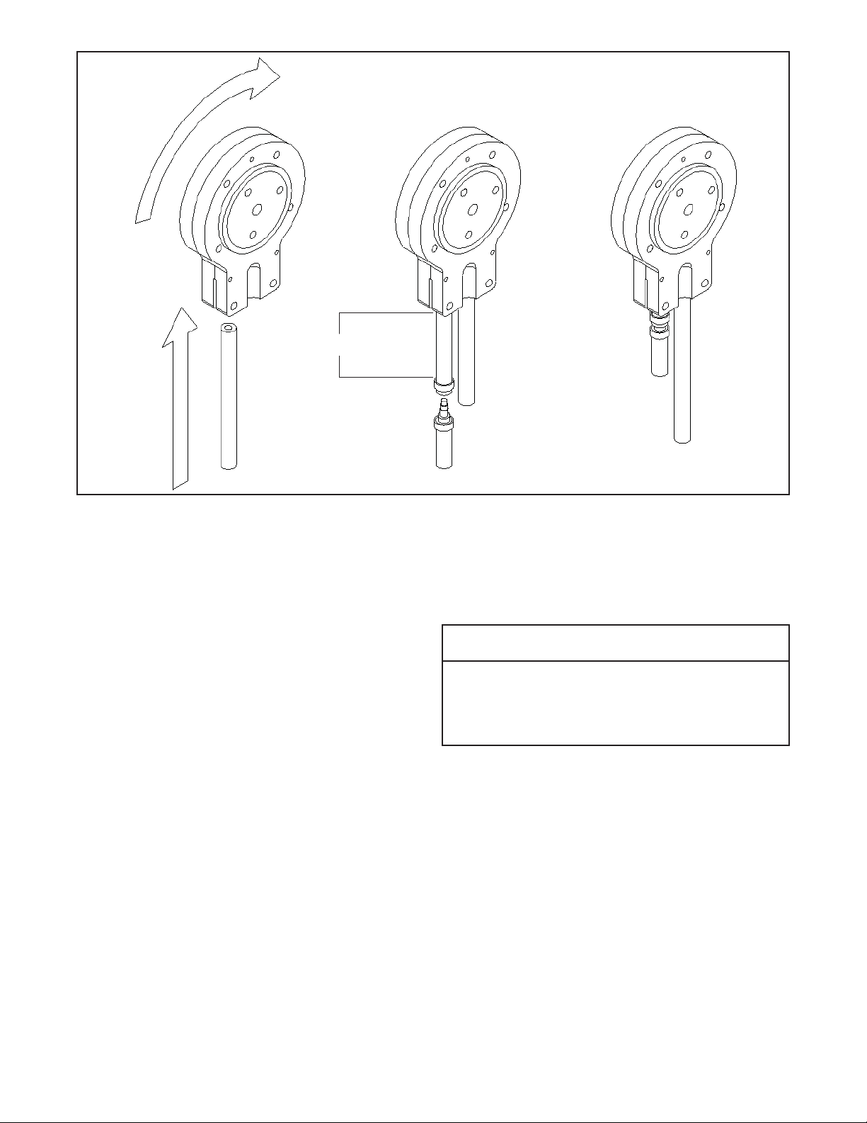
Page 28

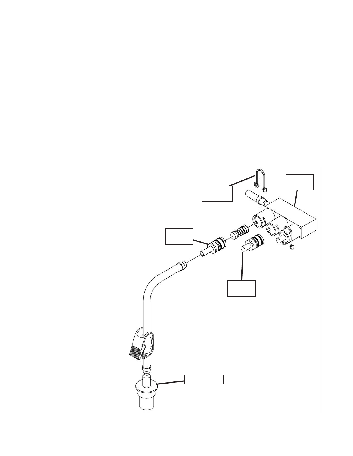
Figure 3-11 Mix Pump Removable Parts
A. Loosen the clamp and remove the air hose from
the pump compressor.
B. Loosen the clamp and disconnect the mix pump
hose. Remove the pickup hose, the mix check
valve and the pickup hose adapter (and bag
adapter if applicable) as an assembly from the
mix container.
C. Completely disassemble the hose assembly and
the check valve (Fig. 3-11). Place hoses, tee,
check valve assembly, and pickup hose adapter in
90° to 110°F (32°C to 43°C) mild detergent water
and wash thoroughly. Use soft bristle brushes to
clean inside of fi ttings. Rinse all parts in clean
90° to 110°F (32°C to 43°C) water.
D. Carefully inspect each part for wear or damage.
Replace worn or damaged parts.
E. Wash the feed tube and the air tube in the cabinet
with 90° to 110°F detergent water and brushes
provided. Rinse with clean, 90° to 110°F water.
F. Prepare two gallons (7.5 liters) of sanitizing
solution using a USDA certifi ed grade sanitizing
solution. Sanitize all removed parts. Allow them
to air dry.
G. Check the Hose Service Record decal to determine
if a hose reposition or a hose replacement is
required.
H. Reassemble both hose assemblies per the
diagram located on the inside of the cab door.
Reconnect the assemblies to the pump hose and
the discharge hose, using the clamps. (Refer to
Section 2.5 Mix Pump).
I. Sanitize assembled machine as per instructions
outlined in Section 3.9.
20
Page 29

SECTION 4
MAINTENANCE AND ADJUSTMENTS
4.1 FREEZER ADJUSTMENT
This section is intended to provide maintenance personnel
with a general understanding of the freezer adjustments.
It is recommended that any adjustments in this section
be made by a qualifi ed person.
4.2 PRODUCT CONSISTENCY
ADJUSTMENT
The operator can adjust product consistency by modifying the Fine Adjustment setting on the membrane switch.
This is the only adjustment that can be made by the operator without using a pass code key sequence. Product
consistency fi ne adjustment allows a 0.4 amp maximum
adjustment to the drive motor amp draw cutout. Increasing
this setting will increase the drive motor amperage cutout
and increase product consistency. Follow the instructions
below to make fi ne adjustments to product consistency.
A. Place the Main Freezer Power switch in the ON
position.
B. Press the SET button on the Control Panel once.
Fine Adj will appear on the LCD screen.
C. Press the up arrow button until the desired
consistency setting is displayed. The higher the
number, the fi rmer the product consistency. The
control may be set from 1 to 9. The value increases
by 1 each time the up arrow button is pressed.
After the value reaches 9, numbering restarts at
0. The 0 setting cannot be set.
D. Press the SET button once to save the setting
and return to the current mode display.
4.3 LOCKING THE CONTROL PANEL
The IntelliTec control has a tamper proof mode to prevent
unauthorized use. When set, all buttons on the control
panel are disabled. Follow the instructions below to lock
the control panel
A. Press and hold the PUSH TO FREEZE button
for at least 5 seconds.
B. While still holding the PUSH TO FREEZE button,
press the CLEAN button once.
C. Release both buttons. An asterisk (*) will appear
on the bottom line of the display, indicating that
the control is in the lock out mode.
NOTE:
Repeat steps A, B, and C to unlock the control
panel.
4.4 OBTAINING READINGS AND
MODIFYING SETTINGS (SERVICE PERSONNEL
ONLY)
Readings and settings on the IntelliTec control are accessed through the IntelliTec control menu settings.
Locating freezer readings and system function settings
are done using the up arrow () and left arrow () buttons on the membrane switch. A printed IntelliTec Menu
Settings sheet is located in the information pouch behind
the header panel.
IntelliTec Control Readings
To obtain freezer readings, locate the value on the freezer’s
menu settings sheet and follow the steps below.
A. Press and hold the SEL button for 8 seconds. While
still holding the SEL button, press the up arrow
button (). The LCD screen will read DISPLAY.
B. Release both buttons.
C. Press the up arrow button () to navigate to the
correct reading under DISPLAY or press the left
arrow () button to navigate to the ERRCODES
menu.
D. Press the up arrow () and left arrow () buttons
to navigate through the rest of the readings as
needed.
E. When all readings have been obtained, press
the up arrow button () from ExitMenu to return
to the current mode display.
Modifying Control Settings
To change the value of a system function, locate the
function on the IntelliTec Settings Menu and follow the
steps below.
Figure 4-1 Membrane Switch
21
Page 30

IMPORTANT:
Before making changes to any settings, record
the original values. If the setting changes do not
achieve desired results, return settings to their
original values.
A. Press and hold the SEL button for 8 seconds. While
still holding the SEL button, press the up arrow
button (). The LCD Screen will read DISPLAY.
B. Release both buttons.
C. Press the left arrow button () to get to the correct
menu (Basic, Advanced, or Storage).
D. Press the up arrow button () to navigate to the
value that needs to be changed.
E. Press the SET button to enter the edit mode.
F. Press the up arrow button () to change the
setting.
G. Press the SET button to save the setting and exit
the edit mode.
H. Press the up arrow () and the left arrow ()
buttons to navigate through the rest of the settings
as needed.
I. When all changes have been completed, press
the up arrow button () from ExitMenu to return
to the current mode display.
4.5 READINGS (SERVICE PERSONNEL
ONLY)
The IntelliTec control continuously monitors and records
temperatures, voltages, amps, and error code details.
Each reading is benefi cial to service personnel when
troubleshooting.
DISPLAY READINGS
Following are the readings available under the DISPLAY
menu:
Cabinet
The temperature of the cab is constantly monitored
by the IntelliTec control.
Cycles (count)
This reading counts down the number of cycles
in the current “Serve Mode”. The starting value
is dependent upon the Cycles setting on the
IntelliTec control.
°F and amps
Suction line temperature on the freezing cylinder
and drive motor amps are available on the same
screen to assist with setup and troubleshooting.
Aux. Temp (°F)
This reading provides the ambient temperature
around the IntelliTec control board.
Supply V (VAC)
A calculated input voltage is recorded.
ERROR CODE READINGS
The following details are recorded under the ERRCODES
menu for each of the last 25 error codes received:
Err1 (hours)
A numerical count of the last 25 error codes is
recorded. When the 26th error has occurred,
the earliest error code is erased. A timer also
begins when an error occurs. The timer records
the number of hours since the error occurred. If
power to the freezer is interrupted, the timer will
stop until power has been restored.
°F and amps
The suction gas temperature on the freezing
cylinder and the drive motor amps are recorded
at the time of the error.
Aux. Temp (°F)
Ambient temperature of the IntelliTec control board
is recorded at the time of the error.
Str (°F)
The storage temperature is recorded at the time
of the error.
VAC and Mode
A calculated input voltage and mode at which
the error occurred are recorded. Following are
descriptions of each mode:
Mode Description
0 Start of freezing cycle
1 Compressor and drive motor on
2 Stir Cycle
3 Compressor off
4 “Standby Mode”
5 “Sleep 1 Mode”
6 “Sleep 2 Mode”
7 “Clean Mode”
8 Startup
9 Storage only refrigeration
10 Freezing cycle is shut down
11 Door safety switch triggered
12 High pressure cutout
Up Time (hours)
This value is a record of the total time the freezer
has been in service. If power is interrupted, the
timer will stop until power is restored. This timer
does not reset.
22
Page 31

RUN STATISTICS
In addition to dynamic readings and recorded
error code details, the IntelliTec control records
rolling averages of run statistics. Following are the
readings available under the RUNSTATS menu:
On Times (sec)
The control records the time of each freezing
cycle and provides a rolling average.
Off Times (sec)
The control records the time between freezing
cycles and provides a rolling average.
Brl. Min (°F)
The lowest average barrel temperature is
recorded.
Brl. Max (°F)
The highest average barrel temperature is
recorded.
Stor Min (°F)
The lowest average cabinet temperature is
recorded.
Stor Max (°F)
The highest average cabinet temperature is
recorded.
Power On (hrs)
This value is a record of the time the freezer has
been in service. If power is interrupted, the timer
will reset.
4.6 ADJUSTMENTS (SERVICE PERSONNEL
ONLY)
The following adjustments directly affect product consistency and length of time in “Serve Mode”. The default
settings have been created using a 5% milkfat soft serve
mix and provide optimal product consistency while prolonging product life.
CutOut (amps)
It is recommended to set the CutOut value at
initial startup and when changing mix types.
Adjustments to this setting directly affect the
length of the freezing cycle which changes product
consistency. To properly set the CutOut value,
refer to section 3-10.
Cut In T (°F)
After the consistency value has been determined,
the Cut In T value can be adjusted. The Cut In
T is the temperature of the refrigerant gas in the
evaporator at the front of the freezing cylinder.
Changing this setting changes the temperature at
which the freezing cycle starts. This value along
with the CutOut value determines the range of
temperatures (or “temperature window”) of the
product. Decreasing the temperature decreases
the temperature window and, under normal use,
increases the amount of freezing cycles. This
creates a greater chance of product breakdown
by stirring the product often. Increasing the Cut
In T increases the temperature window, which
decreases freezing cycles and increases the
chance of heat shock within the product.
Cycles (count)
This setting determines the number of freezing
cycles during “Serve Mode”. Increasing the value
will increase the total time in “Serve Mode”. Factory
default is 20 cycles, which results in “Serve Mode”
lasting about 2-1/2 hours without the PUSH TO
FREEZE button being pressed or a spigot handle
being pulled. If the PUSH TO FREEZE button is
pressed or the spigot handle is pulled at any time
during “Serve Mode”, the Cycles count will reset.
4.7 OTHER SETTINGS (SERVICE
PERSONNEL ONLY)
Changing any setting on the IntelliTec control will alter
freezer operation and affect the product temperature,
consistency, or life. Refer to the IntelliTec Control System
Settings sheet located in the information pouch behind
the header panel of the freezer. If any of the following
settings on the IntelliTec control differ from the System
Settings sheet, it is recommended to return those settings
to factory defaults.
Stir On (sec)
Adjustments to this setting affect the amount of
time the auger rotates in the stir cycle. The stir
cycle occurs in “Serve Mode”, “Standby Mode”,
and “Sleep 2 Mode”.
Stir Off (sec)
Adjustments to this setting affect the time between
stir cycles. The stir cycle occurs in “Serve Mode”,
“Standby Mode”, and “Sleep 2 Mode”.
On Time (sec)
Increasing this value will increase the length of
the freezing cycle during “Standby Mode”.
23
Page 32

Off Time (sec)
Increasing this value will increase the time between
freezing cycles in “Standby Mode” and result in
an increase of product temperature in the barrel.
Stb Time (sec)
This setting determines the total amount of time
in “Standby Mode”.
Sl1DrvOn (sec)
Adjustments to this setting affect the amount of
time the auger rotates in the stir cycle. This stir
cycle only occurs in “Sleep 1 Mode”.
Sl1DrOff (sec)
Adjustments to this setting affect the time between
stir cycles. The stir cycle only occurs in “Sleep 1
Mode”.
Sl2CutIn (°F)
Changing this setting affects the temperature at
which the freezing cycle starts in “Sleep 2 Mode”.
Sl2CtOut (°F)
Changing this setting affects the temperature at
which the freezing cycle stops in “Sleep 2 Mode”.
DftOffTm (sec)
In “Serve Mode”, this value determines the
maximum time without a freezing cycle. If this
value is met, a freezing cycle will start. In the event
of a freezing cylinder temperature sensor failure,
this value affects the amount of time between
freezing cycles during “Serve Mode”.
Refriger
This setting changes how the control handles
the storage refrigeration cycle. The setting for
the SU412 is Cabinet.
CabCutIn (°F)
If the Refriger value is set to Cabinet, this
setting determines the temperature at which
the refrigeration cycle starts. If None, 1 Hopper,
or 2 Hopper is selected for the Refriger setting,
CabCutIn will not be shown on the IntelliTec menu.
CabCtOut (°F)
If the Refriger value is set to Cabinet, this
setting determines the temperature at which
the refrigeration cycle stops. If None, 1 Hopper,
or 2 Hopper is selected for the Refriger setting,
CabCtOut will not be shown on the IntelliTec
menu.
Cab Off
If the Refriger value is set to Cabinet and the
temperature sensor in the cabinet fails, this setting
determines the time between refrigeration cycles.
If None, 1 Hopper, or 2 Hopper is selected for the
Refriger setting, Cab Off will not be shown on the
IntelliTec menu.
Cab On
If the Refriger value is set to Cabinet and the
temperature sensor in the cabinet fails, this setting
determines the length of the refrigeration cycle. If
None, 1 Hopper, or 2 Hopper is selected for the
Refriger setting, Cab On will not be shown on the
IntelliTec menu.
4.8 OVERRUN ADJUSTMENT
The product, when served, is a combination of air and
mix. Overrun is a measure of the amount of air blended
into the mix.
Overrun can be expressed in terms of the amount of
weight loss for a given volume. For example, if a pint of
liquid mix weighs 18 ounces and a pint of frozen product
with air added weighs 12 ounces, the overrun is said to
be 50 percent: 18 oz. - 12 oz. = 6 oz., (6/12) x 100 = 50%
The overrun can be checked by placing a one pint container on an ice cream scale and zeroing out the scale.
Then fi ll a one pint container with frozen product. The
container should be fi lled over the top and leveled with
a straightedge. The product should not contain any air
pockets. When weighed on an ice cream scale, one pint
of product should weigh 12 to 13 ounces.
The mix pump has been preset at the factory to produce
a product with approximately 40% overrun. Because of
differences in mix formulation, temperatures and barometric pressure, this fi gure may vary. It will be necessary
for approximately 2 gallons of mix to be pumped through
the freezer before overrun changes in the product are
noticeable.
Overrun is controlled by the length of the air compressor
piston stroke within the piston cylinder. Lengthening the
stroke within the cylinder will increase overrun. Conversely,
shortening the stroke will decrease overrun. To perform
an overrun adjustment, refer to the following procedure:
WARNING
Hazardous voltage
The Main Freezer Power switch must be placed in
the OFF position when disassembling for servicing.
The freezer must be disconnected from electrical
supply before removing any access panel. Failure
to disconnect power before servicing could result
in death or serious injury.
24
Page 33

A. Turn the mix pump switch to the OFF position.
Disconnect power sources/circuit breakers.
B. Remove the back panel from the freezer.
C. On the air compressor side of the pump, locate
the long/slender piston rocking arm. The rocking
arm downward travel is limited by a stationery
cam. On the face of the cam there is an overrun
setting indicator plate numbered 3 through 8 and
an adjustment knob (Fig. 4-2).
Overrun
Adjustment
Knob
Figure 4-2 Overrun Adjustment
D. The overrun setting is indicated by a pin.
E. To adjust overrun, loosen the allen-head screw
(located within the center of the adjustment knob)
with the 5/32” allen wrench provided. Rotate the
adjustment knob counterclockwise to a higher
number for higher overrun, or clockwise to a lower
number for lower overrun. Each number multiplied
by 10 represents the overrun percentage (i.e.
setting 4 = 40% overrun).
F. Tighten the allen screw, then place the wrench
back in its clip. Replace the lower back panel and
secure with the four screws. Turn the mix pump
power switch to the ON position.
4.9 MIX PUMP HOSE REPOSITION
Mix pump hose must be repositioned every 800 gallons
of mix pumped or every 2 weeks. Failure to reposition
the hose will result in reduced mix pump liquid capacity,
dispense stoppage, popping, and possible mix pump hose
leakage. Follow the steps below to reposition the hose:
A. Run cleaning solution through pump.
B. Turn the pump off and relieve any pressure by
opening the spigot.
C. Grasp the pickup hose end of the mix pump hose
with one hand and turn the pump on. Pull down
on the pickup hose end until 12 to 14 inches of
tubing has fed through the pump then turn the
pump off (Fig. 4-3).
12” to 14”
Pickup
End
Figure 4-3 Pump Hose Reposition
D. Loosen the small clamp at the pick-up hose
adapter and disconnect the mix pump hose.
E. Cut 7-1/2 inches off the end of the mix pump
hose.
F. Reconnect the mix pump hose to the adapter.
G. Continue normal operation. Mix hose will
automatically reposition itself with the adapter
near the black cover.
NOTE
Each hose is long enough for 3 repositions before
replacement is required.
4.10 MIX PUMP HOSE REPLACEMENT
Mix pump hose must be replaced when tubing cannot be
further repositioned (every four to eight weeks). Failure
to comply will result in hose failure and possible pump
damage. Follow the steps below to replace the hose:
A. Run cleaning solution through pump.
B. Turn the pump off and relieve any pressure by
opening the spigot.
C. Disconnect the mix pump hose at each end.
D. Grasp the discharge hose end with one hand and
turn the pump on. Pull down on the hose until all
of the remaining hose is removed from the pump.
Turn pump off.
E. Rotate pump roller assembly so one roller is at
the 6:00 position.
F. Use a brush that fi ts in the opening and clean the
pump roller assembly, fi rst with detergent water
and then clear water.
25
Page 34
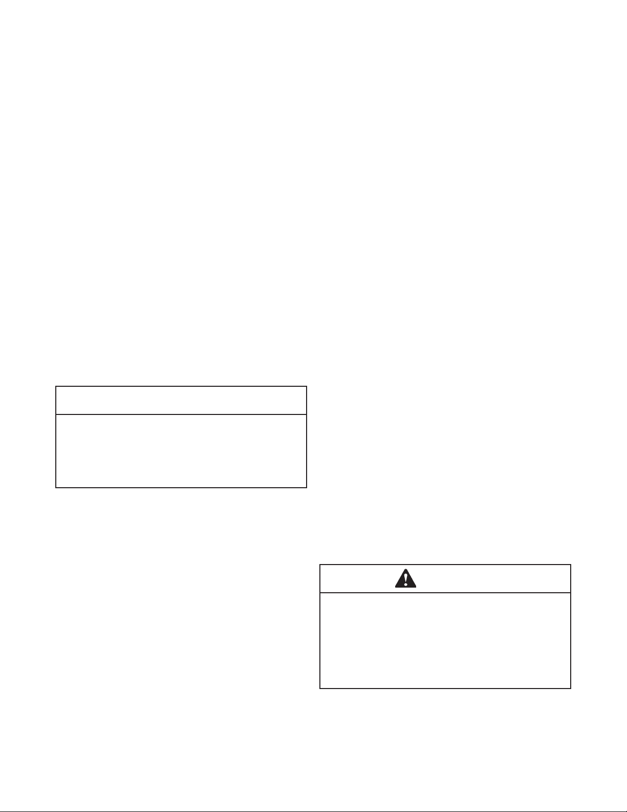
G. Connect the new mix pump hose to the pickup
hose adapter using the small clamp.
H. Feed one end of the mix pump hose into the
pickup hose side (left) of the black cover.
NOTE
Feed the tube into the clamp so the natural curve of
the tube is towards the outside of the black cover.
This prevents the hose from looping around the
black cover twice.
I. Gently push the hose into the black cover until it
begins to feed.
J. Allow the hose to feed itself through the pump
until about 6” (15cm) remains on the entering
side.
K. Turn pump off.
L. Connect the mix pump hose to the elbow fi tting
(located on the left side of the mix line manifold)
using a small hose clamp. Be careful not to twist
the mix hose.
M. Turn the pump on.
N. Allow the remaining 6” (15cm) of tubing to feed
through the pump until the hose adapter prevents
further feeding.
O. Turn the pump off.
CAUTION
Risk of Product Damage
Air/Mix Tee must remain below the black cover
clamp. If the Tee is above the pump, the mix may
drain into the air compressor, resulting in pump
damage.
D. Press the up arrow button () once to navigate
to the CabCutIn value. Record this value.
IMPORTANT:
Before making changes to any settings, record
the original values. If the setting changes do not
achieve desired results, return settings to their
original values.
E. Press SET button to enter edit mode.
F. Press the up arrow button () to increase the
number to the value required. The value increases
by 1 each time the up arrow button () is pressed.
After the value reaches 9, numbering restarts at
0.
G. Press SET button to save the setting and exit the
edit mode.
H. Press the up arrow button () once to navigate
to the CabCtOut value. Record this value.
I. Press SET button to enter edit mode.
J. Press the up arrow button () to increase the
number to the value required. The value increases
by 1 each time the up arrow button () is pressed.
After the value reaches 9, numbering restarts at
0.
K. Press SET button to save the setting and exit the
edit mode.
L. Press the up arrow () and left arrow () buttons
to navigate to ExitMenu.
M. Press the up arrow button () from ExitMenu to
return to the Mode Screen.
N. Locate the Specifi cation Sheet for SU412 Control
behind the header panel and record the new
values on this sheet.
P. Connect the free end of the mix pump hose to the
3-way Tee. When all connections are complete,
the 3-way Tee must be lower than the black pump
housing.
Q. The pump is now ready to sanitize.
4.11 CAB TEMPERATURE ADJUSTMENT
Cab temperature is monitored and controlled by two settings on the IntelliTec control: CabCutIn and CabCtOut.
The cut in value determines the temperature at which the
refrigeration cycle starts. The cut out setting determines
when the cycle stops. To change the CabCutIn or CabCtOut, follow the steps below:
A. Press and hold SEL button for 8 seconds. While
still holding the SEL button, press the up arrow
button (). The LCD Screen will read "Display".
B. Release both buttons.
C. Press the left arrow button () three (3) times to
navigate to the Storage menu.
4.12 DRIVE BELT TENSION ADJUSTMENT
To check belt tension, follow the steps below:
A. Remove a side panel and the back panel.
WARNING
Hazardous voltage
The Main Freezer Power switch must be placed in
the OFF position when disassembling for servicing.
The freezer must be disconnected from electrical
supply before removing any access panel. Failure
to disconnect power before servicing could result
in death or serious injury.
B. Use a Burroughs Belt Tension Gauge to set the
tension for the drive belt. Set the belt tension to
15 - 25 lbs.
26
Page 35

C. If an adjustment is necessary, loosen the four
motor plate retaining nuts, adjust belt tension
then retighten the four nuts.
D. Using a straightedge, check that the drive motor
pulley is aligned with the speed reducer pulley.
Align the pulley if necessary.
NOTE
Belt life will be increased if new drive belts are
tightened after two or three weeks of operation.
4.13 CONDENSER CLEANING (AIR-COOLED
FREEZERS)
The condenser requires periodic cleaning. To clean the
condenser, refer to the following steps:
A. Lift the condenser fi lter off of the freezer cover
panel. Visually inspect the condenser fi lter for dirt
(Fig. 4-4).
Figure 4-4 Removing Condenser Filter
B. If the condenser fi lter is dirty, vacuum or brush
it clean. Rinse it with clean water and allow it to
dry before replacing it on the freezer.
NOTE
If the condenser is not kept clean, refrigeration effi ciency will be lost.
4.14 PREVENTATIVE MAINTENANCE
It is recommended that a preventative maintenance
schedule be followed to keep the freezer clean and operating properly. The following steps are suggested as a
preventative maintenance guide.
The United States Department of Agriculture and the Food
and Drug Administration require that lubricants used in
food zones be certifi ed for this use. Use lubricants only in
accordance with the manufacturer’s instructions.
A. Daily checks
Check for any unusual noise or condition and
repair immediately.
B. Monthly checks
1. Check drive belts for wear and tighten belts if
necessary. (Refer to section 4.12)
2. Check the condenser fi lter for dirt. (Refer to
section 4.13).
4.15 EXTENDED STORAGE
Refer to the following steps for winterizing the freezer or
for storing the freezer over any long period.
A. Clean all of the parts that come in contact with
mix thoroughly with warm detergent . Rinse in
clear water and dry all parts. Do not sanitize.
NOTE
Do not let cleaning solution stand in freezer barrel
or mix pump during the shutdown period.
B. Remove, disassemble, and clean the front door,
auger shaft, and mix pump. Leave disassembled
during the shutdown period.
C. Place the plastic scraper blade in a plastic bag
with a moist paper towel. This will prevent the
fl ights from becoming brittle if exposed to dry air
over an extended period (over 30 days).
D. For water-cooled freezers that are left in unheated
buildings, or buildings subject to freezing, the water
must be shut off and disconnected. Disconnect
the fi ttings at the water inlet and the water outlet
lines of the freezer. The fi ttings are located at the
rear of the freezer. Run the compressor for 2 - 3
minutes to open the water valve. Blow out all the
water, fi rst through the water inlet, then through
the water outlet lines with air or carbon dioxide.
Drain the water supply line coming to the freezer.
E. Place the Pump OFF/ON switch and the Main
Freezer Power OFF/ON switch in the OFF
position.
F. Disconnect the freezer from the source of the
electrical supply in the building.
27
Page 36

28
Page 37

SECTION 5
!" #
$
%
$
%
&%
!''(
)(* #
&+
!,- #
.
/
+
%0!1231- #
45
! #
&
5
!" #
!" #
REFRIGERATION SYSTEM
5.1 REFRIGERATION SYSTEM
The U412 refrigeration system has two functions:
Medium-Temperature - Maintaining product
temperature in the cab unit and providing
refrigeration to the mix transfer line.
Low-Temperature - Producing and maintaining
high quality shake in the freezing cylinder.
The system is designed for effi cient use with R404A
refrigerant. The proper charge is indicated on the information plate.
5.2 REFRIGERANT RECOVERY AND
EVACUATION
Refer to the following procedures to properly recover and
evacuate the refrigeration system. Do not purge refrigerant into the atmosphere.
NOTE
For qualifi ed service personnel only. Anybody work-
ing with refrigerants must be certifi ed as a T echni-
cian TYPE I as required by 40 CFR 82 Subpart F
and hold all State and/or local refrigerant handling
certifi cations. In addition, all handling, storage, and
disposal of refrigerants must be in accordance with
Environmental Protection Agency (EP A) guidelines
and standards and all State and local guidelines
and standards.
WARNING
Hazardous voltage
The Main Freezer Power switch must be placed in
the OFF position when disassembling for servicing.
The machine must be disconnected from electrical
supply before removing any access panel. Failure
to disconnect power before servicing could result
in death or serious injury.
Figure 5-1 Water Cooler Refrigeration System
29
Page 38

A. Refrigerant Recovery
1. Disconnect the machine from the electrical supply
before removing any panels for servicing.
2. Remove all panels.
3. Connect the recovery unit to the suction and
discharge service valves of the compressor.
4. Locate the compressor contactor behind the
header panel and disconnect the brown wire #65.
5. Wrap electrical tape around the wire to insulate
it.
6. Remove the belt from the pulley to allow the drive
motor to spin freely.
7. Connect power to the machine.
8. Turn the Main Power OFF/ON switch and Freezing
Cylinder OFF/ON switch to the ON position.
CAUTION
The solenoid valves must be energized to allow all
refrigerant to be recovered and to prevent injury
when brazing.
9. Press the Push To Freeze button on the IntelliTec
control. This will energize the solenoid valves.
10. Operate the recovery unit per manufacturer’s
instructions
NOTE
If recovery is not completed after 20 minutes, press
the Push T o Freeze button again. This will keep the
solenoid valves open.
B. Evacuating the Refrigeration System
1. Close any open ports in the refrigeration system.
2. Connect a vacuum gauge to one of the access
fi ttings next to an evaporator.
3. Connect the evacuation unit to the suction and
discharge service valves of the compressor.
4. Locate the compressor contactor behind the
header panel and disconnect the brown wire #65.
5. Wrap electrical tape around wire to insulate it.
6. Remove belts from the pulleys to allow drive
motors to spin freely.
7. Connect power to the machine.
8. Turn the Main Power OFF/ON switch and Freezing
Cylinder OFF/ON switches to the ON position.
9. Press the Push To Freeze button on the IntelliTec
control. This will energize the solenoid valves.
10. Evacuate the system until the gauge reads 300
microns of mercury (300μ Hg) for 5 continuous
minutes.
NOTE
If evacuation is not completed after 20 minutes,
press the Push To Freeze button again. This will
keep the solenoid valves open.
11. If the system will not maintain a standing vacuum
test with the vacuum pump off (gauge increases
towards atmosphere), fi nd the leak, fi x it, and
evacuate again.
5.3 REFRIGERANT CHARGING
Refer to the following procedures to properly charge
the refrigeration system. Stoelting recommends liquid
refrigerant charging.
NOTE
For qualifi ed service personnel only. Anybody work-
ing with refrigerants must be certifi ed as a T echni-
cian TYPE I as required by 40 CFR 82 Subpart F
and hold all State and/or local refrigerant handling
certifi cations. In addition, all handling, storage, and
disposal of refrigerants must be in accordance with
Environmental Protection Agency (EP A) guidelines
and standards and all State and local guidelines
and standards.
A. Ensure the electrical supply has been removed
before continuing.
WARNING
Hazardous voltage
The Main Freezer Power switch must be placed in
the OFF position when disassembling for servicing.
The machine must be disconnected from electrical
supply before removing any access panel. Failure
to disconnect power before servicing could result
in death or serious injury.
B. If the system has been opened or if there was a
leak, refer to Section 5.2 - Refrigerant Recovery
and Evacuation to evacuate the system prior to
charging.
C. Refer to machine’s information plate for total
charge requirements.
NOTE
The refrigeration system of the U412 is critically
charged. Be sure to charge the system to the weight
listed on the machine’s information plate.
D. For liquid refrigerant charging, connect refrigerant
cylinder to the discharge access fi tting of the
compressor.
E. Energize the three solenoid valves. There are two
liquid line solenoids and one suction line solenoid.
F. Add the proper amount of refrigerant according
to the machine’s information plate.
30
Page 39
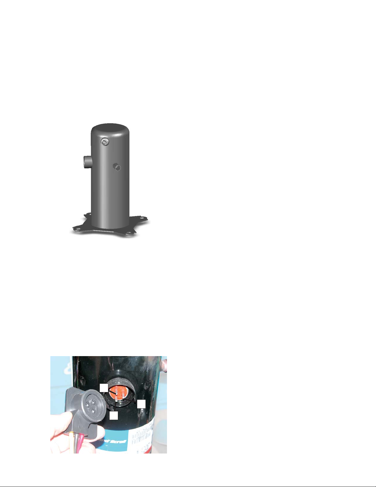
5.4 COMPRESSOR
The U412 has a scroll type compressor (Refer to Figure
5-2). This compressor type uses two spiral shaped scrolls
to compress gas. One scroll rotates around an identical
stationary scroll. Gas is drawn into the compression
chamber by the rotating scroll and is compressed as it
moves towards the center of the chamber. Operation of this
compressor is continuous because, during each rotation,
several gas ‘pockets’ are compressed simultaneously.
Details of the compressor’s starting components are in
Section 6.
Figure 5-2 Scroll Type Compressor
A. Winding Test
To test the compressor motor windings for possible problems, perform the following steps:
A. Disconnect the machine from electrical supply
before removing any panels for servicing.
B. Remove the left side panel.
C. Pull the compressor connector plug off of the
compressor. The compressor has three terminals;
C (common), R (run), and S (start). (Refer to
Figure 5-3)
C
S
R
D. Connect an ohmmeter to the C and R terminals.
Resistance through the run winding should be
1.81Ω ±10%.
E. Connect ohmmeter to terminals C and S.
Resistance through the start winding should be
2.27Ω ±10%.
F. To check if windings are shorted to ground, connect
one ohmmeter lead to a bare metal part on the
compressor (such as any copper line leading to
or from the compressor) and check terminals C,
R, and S.
NOTE
The compressor is equipped with an internal overload protector. If the compressor is warm and ohmmeter readings indicate an open winding, allow up
to one hour for overload to reset.
B. Compressor Removal
A. Disconnect the machine from electrical supply
before removing any panels for servicing.
B. Disconnect the electrical plug from the compressor.
C. Recover refrigerant charge per the instructions
in Section 5.2.
D. Leave the suction and discharge ports open to
prevent pressure buildup during compressor
removal.
E. Remove six inches of insulating tubing on
the suction line going to the compressor and
unsweat the suction and discharge line from the
compressor.
F. Remove the four nuts and washers from the base
of the compressor.
G. Remove the compressor through the side of the
machine.
H. Remove the four rubber compressor mounts from
the compressor.
I. Crimp and braze all open ports of the old
compressor.
NOTE
A compressor returned to Stoelting with any open
ports will void the warranty. ALWAYS crimp and
braze ports on a compressor that has been removed.
C. COMPRESSOR INSTALLATION
A. Disconnect the machine from electrical supply
before removing any panels for servicing.
B. Install the four rubber mounts on the compressor.
Figure 5-3 Compressor Connection
31
Page 40

WARNING
Hazardous voltage
The Main Freezer Power switch must be placed in
the OFF position when disassembling for servicing.
The machine must be disconnected from electrical
supply before removing any access panel. Failure
to disconnect power before servicing could result
in death or serious injury.
C. Install the compressor into the machine, fi tting
the base over the four bolt holes.
D. Install the four washers and nuts onto the bolts
and tighten securely.
E. Remove all tubing plugs from the replacement
compressor.
NOTE
The compressor plugs protect the compressor from
moisture in the air. Do not remove the plugs until
you are ready to install. The compressor must not
be opened to the atmosphere for more than 10
minutes.
F. Leave the suction and discharge ports open to
prevent pressure buildup. Braze the suction and
discharge line to the compressor.
G. Connect the electrical plug to the compressor.
The plug is keyed and will only install one way.
(Refer to Figure 5-3)
H. Replace the drier per the instructions in Section
5.9.
I. Evacuate the system per the instructions in Section
5.2
J. Recharge the system per the instructions in
Section 5.3.
K. Replace the insulating tubing on the suction line.
5.5 CONDENSER
The U412 is available with a water-cooled or an air-cooled
condenser. The capacity of the machine is directly related
to keeping the condenser clean and free of debris.
The water-cooled condenser is a tube and shell type. This
condenser requires cool, clean water to function properly.
Inlet and discharge lines must be 3/8” ID minimum.
The air-cooled condenser is a copper tube and aluminum fi n type. The machine must have a minimum of 3”
of clearance on the sides and 6” clearance at the back
for proper air fl ow.
Condenser Testing
The condenser can be checked for leaks using the bubble
test or using a leak detector.
5.6 EVAPORATOR
The U412 has a freezing cylinder evaporator, a cab
evaporator, and a mix line evaporator.
Evaporator Testing
The evaporator can be checked for leaks using the bubble
test or using a leak detector.
NOTE
Foam insulation in the evaporator will set off electronic leak detectors if disturbed.
5.7 VALVES
A. Thermostatic Expansion Valve (TXV)
The Thermostatic Expansion Valve (TXV) is used to meter
the refrigerant to the evaporator. It does so by maintaining a low, constant superheat in the evaporator. The
self-regulating TXV is preset by the manufacturer and
adjustment is not recommended. Figure 5-4.
Figure 5-4 TXV
TXV Testing & Adjustment
When testing a TXV, run only the evaporator that the
TXV meters. If checking the cab TXV, place the freezing
cylinder switch in the OFF position.
NOTE
The bulb has an indent which must be positioned
against the tubing. Good contact between the
bulb and the suction line is necessary for proper
operation of the valve. The bulb must also be well
insulated.
A. Connect a gauge to the access fi tting on the
suction line next to the evaporator.
B. Connect a thermocouple to the suction line next
to the evaporator.
C. Immediately before the refrigeration cycle ends,
the gauge should read between 20-22 psig.
32
Page 41

D. If the pressure reading is higher than expected,
check to see if there is an overcharge of refrigerant.
E. If the pressure reading is lower than expected,
check to see if there is a low refrigerant charge
or if there is a restriction in the system.
NOTE
The TXV is the LAST component to adjust in the
refrigeration system.
F. The TXV can be adjusted after the steps above are
completed. When adjusting, do not turn the valve
over 1/4 turn (90°). Turn the valve stem clockwise
to increase the superheat or counterclockwise to
decrease the superheat.
TXV Removal
A. Remove the side panel.
B. Remove bulb from suction line exiting from the
evaporator.
C. Recover refrigerant charge per instructions in
Section 5.2.
D. Leave the suction and discharge ports open to
prevent pressure buildup during TXV removal.
E. Remove any insulation from the TXV and
immediate surrounding lines.
F. Apply a heat sink (wet cloth) to the valve dome
(Figure 5-5).
G. Unsweat the TXV and remove.
D. Install bulb on suction line exiting the evaporator
using existing clamp. The bulb has an indent that
must be placed against the tubing.
NOTE
Good contact between the bulb and the suction line
is necessary for proper operation of the valve. The
bulb must also be well insulated.
E. Tighten clamp to 20 in/lb using a torque wrench.
F. Replace insulation to the TXV and surrounding
lines.
G. Replace the drier per the instructions in Section
5.9.
H. Evacuate the system per the instructions in Section
5.2.
I. Recharge the system per the instructions in
Section 5.3.
B. Check Valve
The U412 has 2 magnetic check valves (Refer to Figure
5-6). Each valve is positioned in the suction line and
prevents backfl ow of refrigerant into the evaporator. If
there is reversed fl ow, the product in the freezing cylinder
softens and liquid refrigerant can fl ood into the compres-
sor on startup.
If a check valve needs to be replaced, use a heat sink (wet
cloth) when installing the new valve to prevent damage.
Figure 5-5 TXV Removal
TXV Replacement
To replace the TXV, perform the following procedures:
A. Position the TXV with a heat sink into the system.
B. With the suction and discharge ports open, braze
the TXV into the system using appropriate brazing
material.
C. Remove the heat sink from the TXV.
Figure 5-6 Check Valve
C. High Pressure Cutout
The high pressure cutout stops the compressor if the
discharge pressure reaches 445 psig.
High Pressure Cutout Test
A. Connect a gauge to the access fi tting on the
discharge line.
33
Page 42

B. Disconnect cooling:
Air-Cooled - Disconnect evaporator fan
Water-Cooled - Shut off water supply
C. High pressure cutout should trip when pressure
reaches 445 psig ±9.
High Pressure Cutout Removal
A. Remove the left side panel.
B. Recover refrigerant charge per instructions in
Section 5.2.
C. Leave the suction and discharge ports open to
prevent pressure buildup during removal.
D. Unsweat the high pressure cutout from the suction
line.
E. Disconnect the terminals from high pressure
cutout.
High Pressure Cutout Replacement
A. With the suction and discharge ports open, braze
the capillary tube to the discharge line.
C. Replace the drier per the instructions in Section
5.9.
D. Braze bulb into place on suction line.
E. Evacuate the system per the instructions in Section
5.2.
F. Recharge the system per the instructions in
Section 5.3.
G. Connect the pink wire to the COM terminal and
the brown/gray wires to the #2 terminal.
H. Attach the high pressure cutout to the top of the
inside of the header panel using the two screws
with star washers.
D. Hot Gas Bypass
The hot gas bypass valve is installed in parallel to the
compressor and helps to regulate the compressor temperature (Refer to Figure 5-7). When the cab evaporator
is the only part of the system requiring refrigerant, the
bypass valve will allow discharge gas to bypass into the
suction line to prevent liquid refrigerant from entering the
compressor.
Hot Gas Bypass Adjustment
NOTE
Before adjusting the hot gas bypass, check the EPR
valve and adjust if necessary.
A. Turn the Main Power OFF/ON switch and the
Freezing Cylinder OFF/ON switch in the OFF
position.
B. Connect a gauge to the access fi tting on the
suction line next to the compressor.
Figure 5-7 Hot Gas Bypass
C. Open the cab door and place a piece of tape on
the cab door interlock switch.
NOTE
The cab door remains open for this test. The relatively warm ambient air will keep the cab refrigeration running.
D. Turn the Main Power OFF/ON switch to the ON
position.
E. Wait 3 minutes to allow the gauge to stop moving.
F. Unscrew the seal cap from the top of the valve.
G Using a 5/16” Allen wrench, adjust the valve
counterclockwise to decrease pressure and
clockwise to increase pressure. (Refer to Figure
5-8)
NOTE
Each 360° turn will change the pressure about 6
psig.
H. Adjust the hot gas bypass valve to 18 psig ±1.
34
Figure 5-8 Hot Gas Bypass Adjustment
Page 43
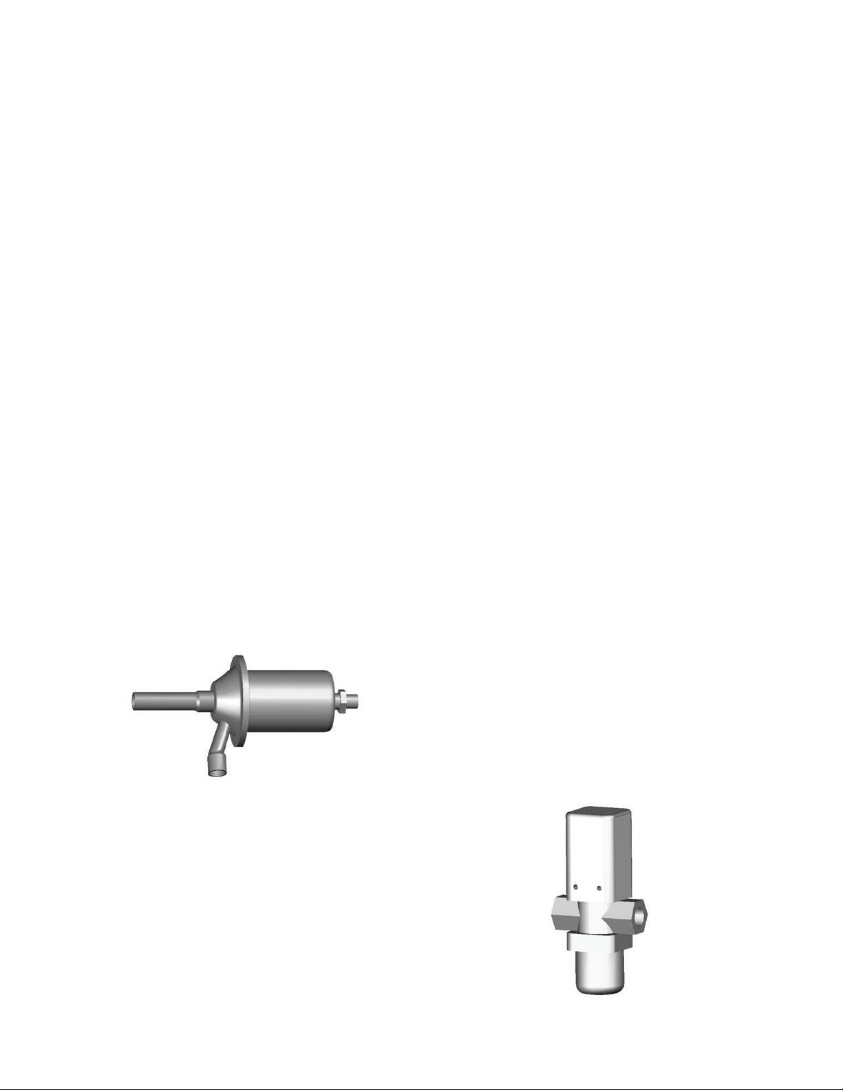
I. Wait 2 minutes to ensure pressure remains stable.
J. Hand-tighten seal cap to valve.
Hot Gas Bypass Removal
A. Remove the side and rear panels.
B. Recover refrigerant charge per instructions in
Section 5.2.
C. Remove insulation around hot gas bypass and
tubing.
D. Leave the suction and discharge ports open to
prevent pressure buildup during hot gas bypass
removal.
E. Apply a heat sink (wet cloth) to the hot gas bypass.
F. Unsweat the hot gas bypass and remove.
Hot Gas Bypass Replacement
To replace the hot gas bypass, perform the following
procedures:
A. Apply a heat sink (wet cloth) to the hot gas bypass.
B. With an open port, braze the hot gas bypass into
the system using appropriate brazing material.
C. Remove the heat sink from the hot gas bypass.
D. Replace the fi lter drier. Refer to Section 5.8 for
details.
E. Evacuate and recharge system per instructions
in Section 5.2.
E. Evaporator Pressure Regulator (EPR)
There is one EPR in the U412 refrigeration system (Refer to Figure 5-9). It is located on the suction line of the
refrigerated mix line and regulates evaporator refrigerant
pressure.
Figure 5-9 EPR Valve
D. Open the cab door and place a piece of tape on
the cab door interlock switch.
NOTE
The cab door remains open for this test. The relatively warm ambient air will keep the cab refrigeration running.
E. If the gauge does not read 78 ±2 then adjustment
is needed.
F. Remove the plastic cap and loosen the locknut
on the EPR. Using a small screwdriver, turn the
adjustment screw counterclockwise 1/2 turn, then
adjust as necessary. Turn the valve stem clockwise
for higher pressure or counterclockwise for lower
pressure.
G. Allow the system to stabilize for 5 minutes to
ensure pressure remains stable.
EPR Removal
A. Remove the side panel.
B. Recover refrigerant charge per instructions in
Section 5.2.
C. Leave the suction and discharge ports open to
prevent pressure buildup during EPR removal.
D. Unsweat the EPR and remove.
EPR Replacement
To replace the EPR, perform the following procedures:
A. Apply a heat sink (wet cloth) to the EPR.
B. With an open port, braze the hot gas bypass into
the system using appropriate brazing material.
C. Remove the heat sink from the hot gas bypass.
D. Replace the fi lter drier. Refer to Section 5.8 for
details.
E. Evacuate and recharge system per instructions
in Section 5.2.
F. Water Valve (Water Cooled Models Only)
The water valve monitors refrigerant pressure and opens
on an increase of pressure. The opening point pressure
is the refrigerant pressure required to lift the valve disc
off the valve seat. (Figure 5-10)
EPR Test and Adjustment
A. Place the Main Power OFF/ON switch and both
Freezing Cylinder OFF/ON switches in the OFF
position.
B. Connect a gauge to the access fi tting on the
suction line between the mix line evaporator and
the EPR.
C. Place the Main Power OFF/ON switch to the ON
position and place the Freezing Cylinder OFF/ON
switch to the OFF position
Figure 5-10 Water Valve
35
Page 44

Water Valve Adjustment
A. Remove the back panel.
B. Connect a gauge to the compressor discharge
access fi tting.
C. Connect the machine to the electrical supply, start
the refrigeration cycle, and read the pressure.
D. The proper gauge reading should be 225-235 psig.
The exit water temperature should be 95-107°F.
E. If the water temperature and high side pressure
are too low, the opening point pressure should
be increased to slow the water fl ow. Turn the
adjustment screw counterclockwise.
F. If the water temperature and high side pressure
are too high, the opening point pressure should
be decreased to increase the fl ow of water. Turn
the adjustment screw clockwise.
Water Valve Removal
The water valve is connected to the refrigeration system
by capillary tube brazed to the discharge line.
A. Turn off and disconnect the water supply. Blow
out the water lines with compressed air or CO2.
B. Recover refrigerant charge per instructions in
Section 5.2.
C. Leave the suction and discharge ports open
to prevent pressure buildup during water valve
removal.
D. Unsweat the capillary tube from the discharge
line.
E. Remove the clamps from the water lines at the
valve.
F. Remove the two screws holding the water valve
to the frame and remove the valve.
Water Valve Replacement
To replace the water valve, perform the following procedures:
A. Position the water valve and attach to the frame
using the two screws.
B. Install the water lines onto the valve with hose
clamps.
C. Leave the suction and discharge ports open
to prevent pressure buildup during water valve
installation.
D. Braze the capillary tube into the system using
appropriate brazing material.
E. Connect the water supply line and turn on the
water supply.
F. Check for leaks in the water lines. If there are no
leaks, turn off the water supply.
G. Replace the fi lter drier. Refer to Section 5.8 for
details.
H. Evacuate and recharge system per instructions
in Section 5.2.
I. Turn on the water and check for leaks in the water
lines with the refrigeration system running.
J. Adjust the valve as necessary.
5.8 SOLENOID
Solenoid valves are installed on the liquid and suction line
of the freezing cylinder evaporator and on the liquid line
of the cab evaporator (Refer to Figure 5-11). A solenoid
valve has a magnetic coil that, when energized, lifts a
plunger and allows refrigerant to fl ow. The solenoids are
activated by the IntelliTec control and determine which
evaporator receives refrigeration.
The suction line solenoid prevents refrigerant fl ow in the
evaporator when the suction pressure drops due to the
operation of the other evaporators in the system.
Figure 5-11 Solenoid Valve
Activating Solenoid Valves
To open the solenoids, follow these steps:
A. Turn the Main Power OFF/ON switch and both
Freezing Cylinder OFF/ON switches to the OFF
position.
B. Locate the compressor contactor behind the
header panel and disconnect the brown wire #65.
C. Wrap electrical tape around wire to insulate it.
D. Remove belts from the pulley to allow drive motor
to spin freely.
E. Connect power to the machine.
F. Turn the Main Power OFF/ON switch and the
Freezing Cylinder OFF/ON switch to the ON
position.
G. Press the Push To Freeze button the IntelliTec
control. This will energize the solenoid valves.
36
Page 45

Solenoid Testing
When activated, a solenoid coil produces a magnetic fi eld.
This fi eld can be detected by placing the tip of a metal
screwdriver close to the retaining screw on the solenoid
coil. The retaining screw will act like a magnet and pull
on the screwdriver tip. Additionally, the solenoid will make
a clicking sound when fi rst activated.
Solenoid Magnetic Coil Removal
A. Remove the side panel.
B. Disconnect the electrical wires.
C. Remove the retaining screw from the top of the
solenoid and pull the magnetic coil off.
Solenoid Magnetic Coil Installation
To replace the magnetic coil, perform the following procedures:
A. Connect the two electrical wires to the magnetic
coil.
B. Push the coil on to the solenoid valve stem.
C. Make sure there is not any foam insulation between
the valve coil and valve body. Trim any excess
insulation.
D. Install the retaining screw onto the top of the coil.
Solenoid Valve Removal
A. Recover refrigerant charge per instructions in
Section 5.2.
B. Remove insulation around valve and attached
refrigeration lines.
C. Apply heat sinks (wet cloth) to the insulated
refrigerant lines near the valve.
D. Leave a port open to prevent pressure buildup
during solenoid removal.
E. Identify and disconnect the two wires from the
solenoid coil.
F. Remove the retainer holding the coil to the solenoid
body and remove the coil.
G. Unsweat the solenoid and remove.
Solenoid Valve Replacement
To replace the solenoid, perform the following procedures:
A. Position the new solenoid with the arrow pointing
toward the direction of fl ow.
B. Apply a heat sink (wet cloth) to the solenoid valve.
C. With the suction and discharge ports open, braze
the solenoid into the system using appropriate
brazing material.
D. Remove the heat sink from the valve.
E. Replace insulation around valve.
F. Replace the fi lter drier. Refer to Section 5.8 for
details.
G. Evacuate and recharge system per instructions
in Section 5.2.
5.9 FILTER DRIER
The fi lter drier must be replaced every time the refrigeration
system is opened for service. A new fi lter drier improves
operation of the entire refrigeration system by stopping
the circulation of moisture and by removing harmful contaminants (Refer to Figure 5-12).
Figure 5-12 Filter Drier
Filter Drier Removal
A. Recover refrigerant charge per instructions in
Section 5.2.
B. Cut the refrigeration line as close to the fi lter drier
as possible and remove drier.
C. Cap the ends of the drier using the plugs from
the new drier.
NOTE
The drier must be capped to prevent moisture from
the environment
Filter Drier Replacement
A. Position the fi lter drier so the arrow is pointing
towards the evaporators (pointing away from the
condenser).
B. Apply a heat sink (wet cloth) to the fi lter drier.
C. With the suction and discharge ports open, braze
the fi lter drier into the system using appropriate
brazing material.
D. Evacuate the system per instructions in Section
5.2.
E. Recharge the system per instructions in Section
5.3.
37
Page 46

5.10 CAPILLARY TUBE
The capillary tube meters refrigerant fl ow in the mix line
evaporator (Refer to Figure 5-13). The amount of fl ow is
dependent on the length and ID of the capillary tube as
well as the refrigerant charge.
Capillary Tube Removal
A. Recover refrigerant charge per instructions in
Section 5.2.
B. Leave a port open to prevent pressure buildup
during capillary tube removal.
C. Remove foam insulation from the capillary tube
at the evaporator inlet.
D. Unsweat the capillary tube and remove.
Capillary Tube Replacement
A. Position the capillary tube in place.
B. Apply a heat sink (wet cloth) to the capillary tube.
C. With the suction and discharge ports open, braze
the capillary tube into the system using appropriate
brazing material.
D.. Replace foam insulation to the capillary tube at
the evaporator inlet.
E. Evacuate the system per instructions in Section
5.2.
F. Recharge the system per instructions in Section
5.3.
5.11 CAB UNIT
The IntelliTec control is programmed to handle refrigeration
of the cabinet independently from the barrel. The control
maintains cabinet temperature between two preset values
(CabCutIn and CabCtOut). If the cabinet door is opened
during a refrigeration cycle, the evaporator fan will continue to run but the refrigeration cycle will be interrupted
to prevent the evaporator coils from icing up.
The refrigeration will run for a maximum of 4 minutes. After
this time is reached, the refrigeration cycle will stop for a
minimum of 3 minutes. At the expiration of 3 minutes, the
control will check cabinet temperature. If product temperature is at or above CabCutIn, a refrigeration cycle will start.
To adjust temperature, refer to Section 4-4 Obtaining
Readings and Modifying Settings.
Figure 5-13 Capillary Tube
38
Page 47

SECTION 6
ELECTRICAL AND MECHANICAL CONTROL SYSTEMS
NOTE
The wiring diagram is available in Section 8.
6.1 INTELLITEC CONTROLLER
The IntelliTec control is Stoelting’s most advanced controller. It combines all of the best features of previous
controllers with advanced sensing and troubleshooting
capabilities.
Understanding the modes of operation and individual control settings will make servicing the control straightforward.
A. COMPONENTS OF CONTROLLER
The IntelliTec control consists of three main components;
the control board (Figure 6-1), the membrane switch
(Figure 6-2), and the display panel module (Figure 6-3).
The membrane switch is connected to the display panel
module via a 9-pin ribbon cable. The display panel module is connected to the IntelliTec control board through a
telephone cord. The IntelliTec control board is connected
to the machine through an 8-pin connector, a 7-pin connector, and a 6-pin connector.
Figure 6-2 Membrane Switch
6.2 CONTACTORS
The compressor and drive motor contactors are mounted
inside the electrical box behind the header panel. There
is one contactor for the compressor and a contactor for
each drive motor.
The IntelliTec control sends electronic signals to trigger
the contactors. Separate signals are used to control each
drive motor contactor and the compressor contactor. The
signals to the contactors are staggered, so the drive motor will always start and stop three seconds before the
compressor. By staggering the starting and stopping of
the drive motor, maximum starting torque is available and
voltage spikes are reduced.
Figure 6-1 IntelliTec Control Board
Figure 6-3 Display Panel Module
39
Page 48

A. CONTACTOR TESTS
The following tests will show if a contactor is working
properly.
1. Open header panel and visually check the
IntelliTec control board.
2. Check for a signal going to contactor. When the
spigot is opened or the Push To Freeze button is
pressed, the DRV LED on the control board will
light up. After three seconds, the CMP LED will
light up (Refer to Figure 6-4). If the LEDs do not
light up, refer to Section 7 Troubleshooting.
NOTE
In addition to the LEDs lighting, there will be an
audible click from the contactors and the motor and
compressor will start.
Protective
Shield
Tension
Adjustment
Nut
CMP LED
DRV LED
Figure 6-4 IntelliTec LEDs
3. Check to ensure contactor is receiving signal.
Read voltage across the coils of the contactor
during a freezing cycle. Voltage should be about
115V. If there is no voltage reading, refer to Section
7 Troubleshooting.
6.3 DRIVE MOTOR
The drive motor is used to rotate the auger assembly.
An internal, normally closed, centrifugal switch starts the
drive motor. The motor has an internal thermal overload.
A. DRIVE MOTOR REMOVAL
1. Disconnect machine from electrical supply before
removing any panels for servicing.
2. Remove the back panel and the right side panel.
3. Remove the electrical cover plate from the back
of the motor.
4. Identify (mark) wires and remove them from the
motor.
5. Remove protective shield from side of machine.
(Refer to Figure 6-5)
Figure 6-5 Motor Removal
6. Loosen the belt tension adjustment nut and remove
the belt. (Refer to Figure 6-5)
7. Remove the motor mounting bolts and shims.
8. Loosen the two allen head screws from the pulley.
9. Remove the pulley and key from the motor shaft.
B. DRIVE MOTOR INSTALLATION
1. Place the drive motor in position and install the
four mounting bolts and shims.
2. Place the pulley and key on the motor shaft.
NOTE
Do not tighten the pulley screws until after the belt
tension has been properly adjusted.
3. Install the belt and tighten the tension bolt.
4. Use a Burroughs Belt Tension Gauge to set the
tension for the drive belt. Set the belt tension to
15 - 25 lbs.
5. Using a straightedge, align the drive motor pulley
with the gearbox pulley. Tighten the two allen
head screws.
6. Install wiring according to wiring diagram (located
behind header panel). Install electrical cover plate.
7. Install protective shield.
8. Install back and side panel.
6.4 CAPACITORS
The compressor start and run contactors are mounted
behind the side panels. The start and run capacitors for
the drive motor is mounted directly onto the motor body.
40
Page 49

Run
Capacitor
Start
Capacitor
Figure 6-6 Compressor Capacitors
A. CAPACITOR TEST
1. Disconnect machine from electrical supply before
removing any panels for servicing.
2. Place the Main Power OFF/ON switch and the
Freezing Cylinder OFF/ON switch in the OFF
position. Remove the right side panel.
3. Remove a lead from one of the capacitor terminals.
WARNING
Hazardous voltage
The Main Freezer Power switch must be placed in
the OFF position when disassembling for servicing.
The machine must be disconnected from electrical
supply before removing any access panel. Failure
to disconnect power before servicing could result
in death or serious injury.
4. Using insulated pliers, discharge the capacitor
by connecting a 20KΩ 5W resistor across the
terminals.
NOTE
Discharge the capacitor even if there is a bleeder
resistor across the terminals. There may be an open
in the bleeder resistor preventing it from working
properly.
5. Disconnect the bleeder resistor from the circuit.
6. Check the capacitance across the terminals. Refer
to the table below for the correct readings.
Rating
Part MFD VAC
Drive Motor Run 231078 50 MFD 370 VAC
Drive Motor Start 231095 500 MFD 125 VAC
Compressors - Start 230638 88-106 MFD 330 VAC
Compressors - Run 230652 35 MFD 440 VAC
Compressors - Run 231057 35 MFD 370 VAC
B. CAPACITOR REPLACEMENT
1. Disconnect machine from electrical supply before
removing any panels for servicing.
2. Place the Main Power OFF/ON switch and the
Freezing Cylinder OFF/ON switch in the OFF
position.
3. Remove leads from the capacitor terminals.
4. Using insulated pliers, discharge the capacitor
by connecting a 20KΩ 5W resistor across the
terminals.
NOTE
Discharge the capacitor even if there is a bleeder
resistor across the terminals. There may be an open
in the bleeder resistor preventing it from working
properly.
5. Pull the capacitor out of its holder and replace.
Make sure the new capacitor has a bleed resistor.
6. Connect the leads to the terminals.
6.5 GEARBOX
A. GEARBOX INSPECTION
Inspect the gearbox and listen for unusual noise. A grinding sound generally indicates a bad gear.
B. GEARBOX REMOVAL
1. Disconnect the machine from electrical supply
before removing any panels for servicing.
2. Remove the front door and remove the auger
shaft.
3. Remove the back panel and right side panel.
4. Remove protective shield from the side of the
machine.
5. Remove the belt.
7. Remove the pulley by loosening the set screws.
8. Remove the four bolts holding the gearbox to the
barrel and mounting bracket.
9. Remove the gear box.
C. GEARBOX INSTALLATION
1. Place the gear box in position and install the
four bolts. Make sure the bolts pass through the
mounting bracket and gear box.
2. Tighten the bolts.
3. Mount the pulley on the gear box shaft and align it
with the motor pulley, then tighten the allen head
screws.
4. Install the belt.
41
Page 50
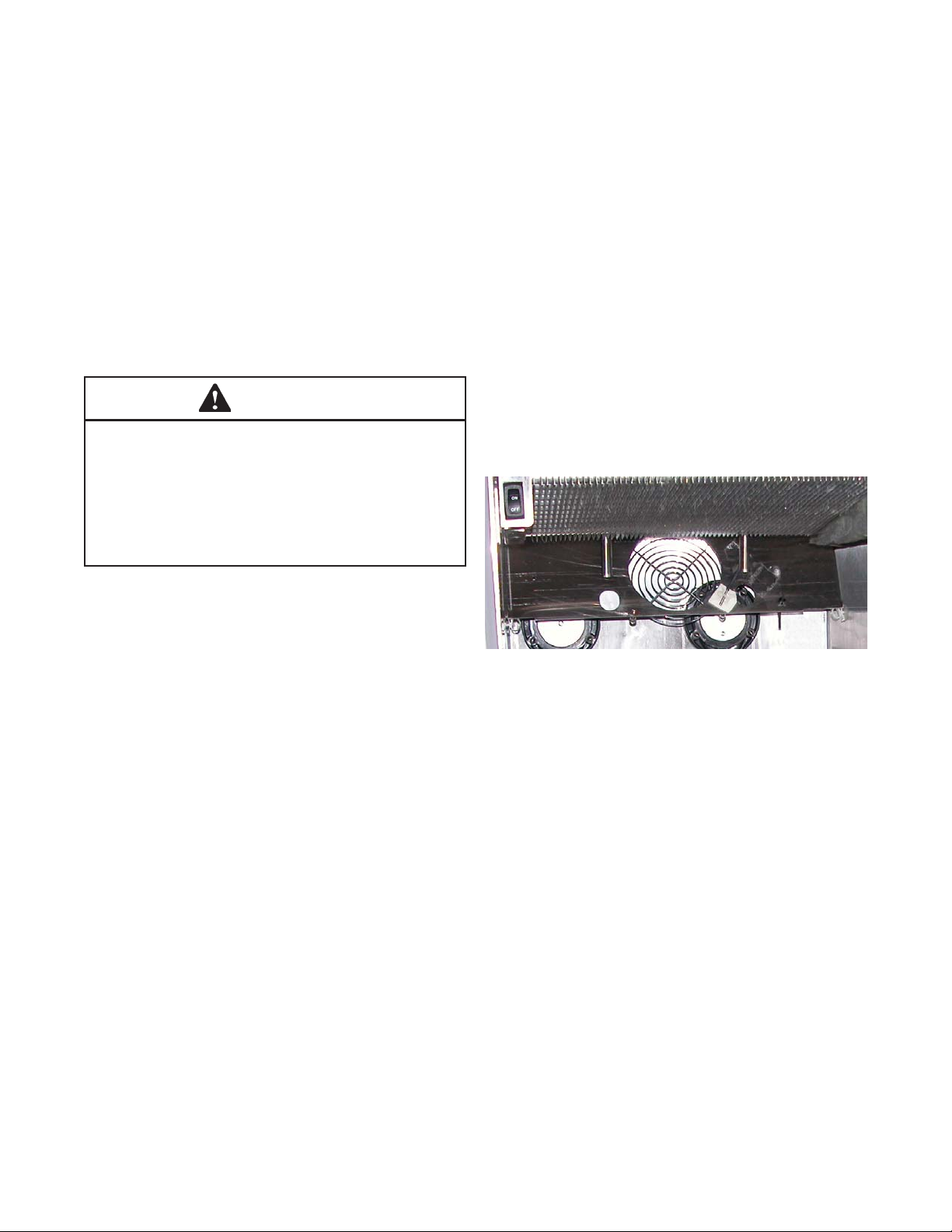
5. Use a Burroughs Belt Tension Gauge to set the
tension for the drive belt. Set the belt tension to
15-25 lbs.
7. If an adjustment is necessary, loosen the four
motor plate retaining nuts, adjust belt tension
then retighten the four nuts.
8. Install the auger shaft and front door.
6.6 CONDENSER FAN MOTOR (AIR-
COOLED ONLY)
A. FAN MOTOR REPLACEMENT
1. Disconnect machine from electrical supply before
removing any panels for servicing.
2. Remove a side panel and the header panel.
WARNING
Hazardous voltage
The Main Freezer Power switch must be placed in
the OFF position when disassembling for servicing.
The machine must be disconnected from electrical
supply before removing any access panel. Failure
to disconnect power before servicing could result
in death or serious injury.
6.7 CAB CONDENSER FAN MOTOR
A. FAN MOTOR REPLACEMENT
1. Shut the machine down and remove mix from the
freezing barrel and cab.
2. Disconnect machine from electrical supply.
3. Remove the mix container and sliding drawer
from the cab.
4. Disconnect the evaporator drain tube and remove
the two thumb screws on the evaporator cover.
Pull the cover off and set aside.
5. Remove the tubes from the mix transfer line and
air line.
6. Remove the four screws on the fan shroud. The
screws are attached to the cab wall.
7. Pull thermistor out of the clip and thread it up
through the hole in the fan shroud.
8. Remove the fan shroud by tilting forward and
pulling down (Refer to Figure 6-7).
3. Trace and disconnect the black and white wires
on the T1 and T2 terminals on the compressor
contactor.
4. Loosen set screw on fan blade.
5. Remove the three bolts from the fan motor
mounting plate and remove the motor.
B. FAN MOTOR INSTALLATION
1. Attach motor to the mounting plate with the three
bolts.
2. Place fan blade on motor shaft and tighten set
screw.
3. Ensure purple wire is terminated.
4. Ensure red wire is terminated with blue wire.
5. Route white and black wires through the front
panel to the compressor contactor.
6. Connect black wire to the T1 terminal.
7. Connect white wire to the T2 terminal.
Figure 6-7 Cab Fan Shroud
9. Remove the two fan bracket screws and
disconnect wires.
10. Connect the wires to the new fan motor.
11. Attach the two screws to the fan motor bracket.
12. Tilt the fan shroud and move it into place.
13. Thread thermistor through hole in fan shroud and
attach it to the clip.
14. Install fan shroud into cab with the four screws.
15. Install evaporator cover with the two thumb screws.
16. Install all tubes and replace sliding drawer and
mix containers.
42
Page 51
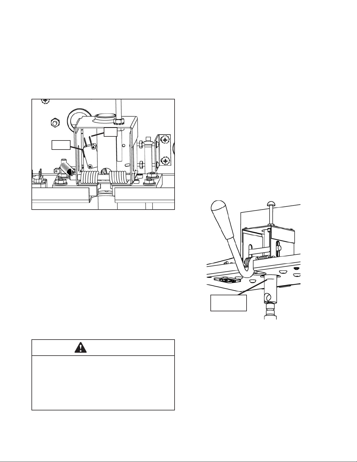
6.8 SWITCHES
A. SPIGOT SWITCH
The spigot switch is a normally closed, held open switch.
When the spigot is pulled, the spigot switch sends a signal
to the IntelliTec control to start the auger drive and refrigeration system. This signal moves the control to “Serve
Mode”, or if it already is in “Serve Mode”, it resets the
cycle count. After serving product, the IntelliTec continues
a freezing cycle until the product reaches consistency.
NC
COM
SPIGOT SWITCH TESTING - ELECTRICAL
1. Disconnect the switch from the circuit by
unplugging the connector.
2. Check resistance readings across the common
(COM) and normally closed (NC) terminals. When
the spigot is closed, the resistance should show
an open. When the spigot is opened, the switch
will close and the resistance should be 0 ohms.
SPIGOT SWITCH ADJUSTMENT
1. Place the Main Power OFF/ON switch and the
Freezing Cylinder OFF/ON switch in the OFF
position.
2. Remove the header panel.
3. Loosen the bolts on the spigot switch.
4. Using a pencil, mark the spigot glide 1/4” from
the spigot housing.
5. Adjust the switch to activate when the plastic glide
reaches the mark.
6. Fully tighten the retaining bolts and remove mark
from spigot glide.
Figure 6-8 spigot Cam Assemly
SPIGOT SWITCH TEST - ADJUSTMENT
NOTE
Adjustments to the spigot switch should be done
after the product is at consistency in “Serve Mode”
or when the machine is empty.
1. Open and close the spigot slowly. There should
be a click when it opens and another when it
closes.
2. The clicking sound should be within the fi rst 1/2”
of the spigot glide movement. If the switch does
not close, an adjustment may be necessary.
WARNING
Hazardous voltage
The Main Freezer Power switch must be placed in
the OFF position when disassembling for servicing.
The machine must be disconnected from electrical
supply before removing any access panel. Failure
to disconnect power before servicing could result
in death or serious injury.
Adjustment
Mark
Figure 6-9 Spigot Switch Replacement
SPIGOT SWITCH REPLACEMENT
1. Remove the header panel.
2. Remove the four bolts that attach the spigot cam
assembly to the panel.
NOTE
Hold the spring on the rear left bolt to prevent it
from snapping back.
3. Remove the assembly.
43
Page 52
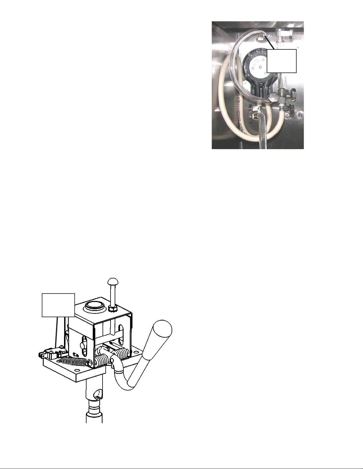
4. Disconnect the connector from the switch and
remove the switch.
5. Install the replacement switch onto the handle
assembly. Do not fully tighten the retaining screws
at this time.
6. Using a pencil, mark the spigot glide 1/4” from
the spigot housing. Adjust the switch to activate
when the spigot handle moves the glide to the
mark.
7. Fully tighten the retaining screws.
8. Attach the connector to the spigot switch.
9. Position the spigot handle assembly in the
electrical box. Install the four bolts that attache
the spigot cam assembly to the panel. Do not
tighten the rear left bolt.
10. Thread the spring onto the rear left bolt using a
needle nose pliers. Turn the bolt until the spring
is threaded to the nut.
11. Tighten all bolts.
12. Replace the header panel and secure with the
two Phillips head screws.
B. BLENDER ACTIVATION SWITCH
The switch is a normally closed, held open switch. When
the spigot is pulled to the right, the switch closes the circuit
and starts the blender.
SWITCH TESTING - ELECTRICAL
1. Disconnect the switch from the circuit by
unplugging the terminals.
Blender
Activation
Switch
Attach
Pressure
Gauge
Figure 6-11 Attaching Gauge to Pump
2. Check resistance readings across the common
(COM) and normally closed (NC) terminals. When
the spigot is closed, the resistance should show
an open. When the spigot is opened, the switch
will close and the resistance should be 0 ohms.
SWITCH REPLACEMENT
1. Remove the header panel.
2. Disconnect the terminals from the switch and
remove the switch.
3. Install the replacement switch onto the assembly
C. PUMP PRESSURE SWITCH
The pump pressure switch maintains 21-24 psig in the
mix line.
PUMP PRESSURE SWITCH TEST
1. Turn off the pump motor.
2. Open the spigot to relieve air pressure in the
system.
3. Connect a gauge between the 1/4” ID tubing and
pump outlet in the cab (Refer to Figure 6-11).
4. Turn on the pump motor.
5. The motor should cutout when the gauge reads
24 psig ±1.
6. Open the spigot and monitor the gauge. The motor
should cutin when the gauge reads 21 psig ±1.
Figure 6-10 Blender Activation Switch
44
Page 53

6.9 POTENTIAL RELAY
The potential relay senses voltage produced by the start
winding. When the rated pick-up voltage is reached, the
relay will open and drop the start capacitor from the circuit.
6.10 TEMPERATURE CONTROL SENSOR
The temperature control sensor is a thermistor used to
sense the temperature of the suction line. As the suction
line temperature increases, the internal resistance of
the thermistor will decrease. Refer to Figure 6-12 for the
relationship between sensor resistance and temperature.
The IntelliTec control board monitors this value. In “Serve
Mode”, when the temperature of the sensor equals the
Cut In T value on the control, a freezing cycle will start.
°F Resistance °F Resistance
-22 176950 40 26100
-20 165200 42 24725
-18 154300 44 23400
-16 144200 46 22175
-14 134825 48 21000
-12 126125 50 19900
-10 118050 52 18875
-8 110550 54 17900
-6 103550 56 17000
-4 97075 58 16125
-2 91025 60 15325
0 85400 62 14550
2 80150 64 13825
4 75275 66 13150
6 70725 68 12500
8 66475 70 11875
10 62500 72 11300
12 58800 74 10750
14 55325 76 10250
16 52100 78 9750
18 49075 80 9300
20 46250 82 8850
22 43600 84 8450
24 41125 86 8050
26 38800 88 7675
28 36625 90 7325
30 34575 92 7000
32 32675 94 6675
34 30875 96 6375
36 29175 98 6100
38 27600 100 5825
Figure 6-12 Resistance Related to Temperature
6.11 SPINNER SPEED CONTROL HARNESS
The blender speed on the SU412 and STU412 machines
is controlled by a wire harness behind the header panel.
There are two wire harnesses available. The blender
speed of the wire harness in the SU412 is 1600 rpm and
the wire harness in the STU412 is 2400 rpm.
To change blender speeds, replace the wire harness.
45
Page 54

46
Page 55

SECTION 7
TROUBLESHOOTING
7.1 ERROR CODES
When the machine experiences a problem, one of the
following error codes will be displayed on the control
panel. Each error code directs you to the system location
of the malfunction.
ERROR CODE MALFUNCTION
1 Soft
2 High Torque
3 Extended Run Time
4 Clean
5 Barrel Sensor
6 Hopper Sensor
7 Drive Motor
8 Cab Sensor
9 High Pressure Cutout
10 Auxiliary Sensor
11 Low Temperature
12 Left Hopper Sensor
13 Right Hopper Sensor
To return the machine to normal operation, any error
causing condition must be corrected and the Freezing
Cylinder Off-On switch must be placed in the Off position
and back in the On position before the affected side of
the machine will return to normal operation.
7.2 TROUBLESHOOTING - ERROR CODES
Error Code 1 - Soft Error
The Soft Error (E1) is an internal control board error
that is logged for future analysis. The refrigeration
is never stopped and the machine will continue
to operate normally.
Error Code 2 - High Torque
If the control panel displays a High Torque Error
(E2), the controller has sensed that the drive
motor is running at 125% of the preset CutOut
amp setting for 10 or more seconds. Very low
and/or fl uctuating supply voltages typically cause
this error. The error can also be caused by faulty
motor or starting components which coulc produce
a high amp draw.
Error Code 3 - Run Time
The Run Time Error (E3) occurs when the
compressor runs continuously for 20 minutes
without the product reaching consistency in
“Serve Mode” or if the product does not reach
proper temperature in “Sleep 2 Mode”. This
error is generally caused by very low mix levels
in the machine’s mix container or from product
breakdown. Another common cause results from
a restriction preventing mix from entering the
freezing cylinder. Check the mix in the cabinet. If
the level mix is low, add mix. If there is a possibility
that the mix is broken down, clean and sanitize the
machine and replace the mix with fresh product.
Ice crystals in the liquid mix container can clog the
mix inlet system and prevent mix from entering
the freezing cylinder. Thoroughly thaw mix per
manufacturer’s recommendations. To check for
ice crystals, pour a small amount of product in
the mix container through a clean and sanitized
sieve or strainer. If ice crystals are in the mix,
check the temperature of the machine’s cabinet.
Check the condition of the neoprene hose running
through the mix pump head. If it shows signs of
wear, rotate or replace it as outlined in Section
3.
In air cooled machines, the Run Time Error may
indicate that airfl ow within the machine has
reduced or stopped. Check the sides and top
of the machine for anything that would restrict
airfl ow.
The Run Time Error may also occur if airfl ow within
the machine has reduced or stopped. Check the
sides and top of the machine for anything that
would restrict airfl ow. Check the condenser fi lter
and clean if necessary. Check the evaporator for
frost that could restrict airfl ow.
The compressor will run continuously if a solenoid
valve fails to open. This could be due to loose
wiring, magnetic coil failure, a stuck valve or a
faulty control board.
After the cause of the problem is found and
remedied place the Freezing Cylinder Off-On
switch in the Off position and back in the On
position.
Error Code 4 - Clean
If the machine is left in the Clean Mode for more
than 20 minutes, the control panel will display a
Clean Error (Error 04). This condition does not
refl ect a problem with the machine itself. The Clean
Error has been programmed into the controller as
a safeguard to protect the machine from potential
damage caused by the machine being accidentally
left in “Clean Mode”. The control will attempt to
restart itself after 5 minutes. The display will then
fl ash and read Restart. To immediately clear the
Clean Error, place the Main Power Off-On switch
in the Off position and back in the On position.
After restarting the machine, a refrigeration cycle
will begin. This protects the product in case the
clean button was pressed by mistake.
47
Page 56

Error Code 5 - Freezing Cylinder Sensor
The Freezing Cylinder Sensor Error (E5) indicates
a failure of the barrel sensor or an extreme out of
range condition (< -34°F or > 99°F). If the control
panel displays an E5, place the Freezing Cylinder
Off-On switch in the Off position and back in the
On position. If the control panel still displays the
error code, refer to the machine’s wiring diagram
and the Temperature Sensor Chart (Figure 7-1).
Check each lead of the sensor to ground for
continuity. If continuity is found, replace the sensor.
To check the resistance of the sensor, place a
thermocouple on the suction line at the exit of
the freezing cylinder. Compare temperature and
sensor resistance with the table as reference. If
measured value does not coincide with a value
on the table (± 400 ohms), replace the sensor.
NOTE
When the machine encounters a Freezing Cylinder
Sensor Error, the machine will continue to run using
preset timers. This mode will allow the operator to
continue serving product until the machine can be
serviced.
°F Resistance °F Resistance
-22 176950 40 26100
-20 165200 42 24725
-18 154300 44 23400
-16 144200 46 22175
-14 134825 48 21000
-12 126125 50 19900
-10 118050 52 18875
-8 110550 54 17900
-6 103550 56 17000
-4 97075 58 16125
-2 91025 60 15325
0 85400 62 14550
2 80150 64 13825
4 75275 66 13150
6 70725 68 12500
8 66475 70 11875
10 62500 72 11300
12 58800 74 10750
14 55325 76 10250
16 52100 78 9750
18 49075 80 9300
20 46250 82 8850
22 43600 84 8450
24 41125 86 8050
26 38800 88 7675
28 36625 90 7325
30 34575 92 7000
32 32675 94 6675
34 30875 96 6375
36 29175 98 6100
38 27600 100 5825
Figure 7-1 Temperature Sensor Resistance
(10K Ohms)
Error Code 6 - Hopper Sensor (single hopper machines)
The Hopper Sensor Error (E6) will not occur on
the U412 machine.
Error Code 7 - Drive Motor
If the control panel displays a Drive Motor Error
(E7), the control does not sense current coming
from the drive motor. Place the Freezing Cylinder
Off-On switch in the Off position and back in the
On position. If the error returns, use the machine’s
wiring diagram and check connections at the
IntelliTec control and at the motor. An E7 may also
be the result of a faulty drive motor contactor.
Error Code 8 - Cab Sensor
A Cab Sensor Error (E8) indicates a cabinet
temperature sensor failure or. This error will also
appear in an extreme out of range condition (<
-34°F or > 99°F). If the control panel displays an
E8, place the Freezing Cylinder Off-On switch in
the Off position and back in the On position. If the
control panel still displays the error condition code,
refer to the wiring diagram and the temperature
sensor value table. Check each lead of the
sensor to ground for continuity. If continuity is
found, replace the sensor. Place a thermocouple
in the cabinet evaporator discharge airstream
(outlet air fl ow). Compare temperature to sensor
resistance using the table as reference. If Cutin/
Cutout values do not coincide with the values on
the table, replace the sensor..
Error Code 9 - High Pressure Cutout
High Pressure Cutout Errors (E9) are usually
caused by a dirty or ineffi cient condenser.
In air cooled condenser models, check for proper
air clearance around the machine.
In water cooled condenser models check for
proper water fl ow.
If the error persists, contact your Authorized
Stoelting Distributor for further assistance.
Error Code 10 - Auxiliary Sensor
An Auxiliary Temperature Sensor Error (E10)
occurs if the temperature sensor on the control
board fails. Place the Freezing Cylinder Off-On
switch in the Off position and back in the On
position. After the cause of the error is determined
and corrected, place the Freezing Cylinder OffOn switch in the Off position and back in the On
position.
48
Page 57

Error Code 11 - Low Temperature
The Low Temperature Error (E11) occurs when the
temperature of the gas refrigerant at the freezing
cylinder sensor falls below -20°F. Although the
machine will not shut down, the active freezing
cycle will immediately end. This error usually
occurs when the machine continues to run in a low
mix condition or if the machine runs out of mix. The
product towards the front of the freezing cylinder
tends to freeze solid. When the temperature on
the freezing cylinder lowers to the preset value,
the IntelliTec control will display an E11.
Error Code 12 - Hopper Sensor
The Left Hopper Sensor Error (E12) will not occur
on the U412 machine.
Error Code 13 - Hopper Sensor
The Right Hopper Sensor Error (E13) will not
occur on the U412 machine.
COMMO TIMEOUT Error
A COMMO TIMEOUT Error indicates a
communication interruption between the display
and the control board. This error can be caused
by a poor connection or a faulty phone cable.
Disconnect and reconnect the telephone cable
at the control board. If the error does not clear,
disconnect and reconnect the telephone cable
at the display panel module. If the error still
appears, the cable may be faulty or the display
panel module may be faulty.
ALTERNATING FLASHING CONTROL PANEL LIGHTS
The display panel lights will fl ash in an alternating
sequence under any error codes. Clear the error
and place the Freezing Cylinder Off-On switch in
the Off position and back in the On position.
The alternating lights will also illuminate if the
Main Power switch is in the On position and the
Freezing Cylinder switch is in the Off position.
49
Page 58

7.3 TROUBLESHOOTING - MACHINE
PROBLEM POSSIBLE CAUSE REMEDY
1. Power to machine is off. 1. Check power to machine.
Drive motor (auger)
“kicks-out”, or
does not run.
Compressor does
not operate.
Product too soft.
Freeze-up. (Product
will not dispense
easily.)
Rear auger seal
leaks.
Spigot leaks.
Drive belts slipping
or squealing.
Mix temperature
too warm in cab.
Mix temperature
too cold in cab.
2. Low line voltage. 2. Check, must be ±10% of nameplate voltage.
3. Product too hard. 3. Raise overrun. (See Section 4)
4. Front door not installed securely. 4. Install front door securely.
1. Power to machine is off. 1. Check power to machine.
2. Low line voltage. 2. Check, must be ±10% of nameplate voltage.
3. Compressor internal overload is cutout.
4. Front door not installed securely. 4. Install front door securely.
1. CutOut setting is too low 1. Adjust CutOut setting to match product
2. Product break down. 2. Fill with fresh product.
1. CutOut setting is too high. 1. Adjust CutOut setting to match product
2. Low overrun setting. 2. Raise overrun. (See Section 4)
3. Low pump pressure. 3. Check pump pressure.
4. Large air pocket in barrel. 4. Purge air from barrel.
5. Auger turning counter-clockwise. 5. Change rotation to clockwise.
1. Seal missing or installed wrong. 1. Install correctly. (See Section 3)
2. Rear seal o-ring missing, broken or
not lubricated.
3. Worn or scratched shaft. 3. Replace shaft.
1. Spigot parts are not lubricated. 1. Lubricate. (See Section 3)
2. Chipped or worn o-rings. 2. Replace o-rings.
3. O-rings on spigot installed wrong. 3. Remove spigot and check o-rings.
4. Nicks or scratched on front door where
spigot is located.
1. Drive belt tension not correct. 1. Adjust belt tension. (See Section 4)
2. Worn belt(s). 2. Replace belts.
3. Low overrun. 3. Check for air leak.
1. Temperature control set too warm. 1. Decrease CabCtOut and CabCutIn (See
2. Cab door is open. 2. Close the cab door.
1. Temperature control set too cold. 1. Increase CabCtOut and CabCutIn (See
3. Check condenser (air cooled)(See Sect. 4), or
water supply (water cooled).
requirements.(See Section 3)
requirements.(See Section 3)
2. Inspect for breakage and lubricate properly
(See Section 3)
4. Replace front door.
Section 4)
Section 4)
50
Page 59

7.4 TROUBLESHOOTING - MIX PUMP
PROBLEM POSSIBLE CAUSE REMEDY
1. Power to pump is off. 1. Supply power to pump.
2. Low voltage. 2. Check for low voltage.
3. Mix pump hose jammed inside black
cover/clamp.
Pump motor does
not run.
4. Pump motor overloaded. 4. Allow internal thermal overload to reset;
5. Pressure switch on pump is defective. 5. Check mechanical operation and continuity of
6. Defective motor/capacitor. 6. Check motor amperage draw and/or capacitor.
7. Defective toggle switch. 7. Check continuity; repair or replace.
Note 1: A properly working pump will fi ll an 8 oz. cup with mix in about 9 seconds.
3. Disconnect pump from power source. Remove
four cover/clamp thumb screws. Separate
cover/clamp halves and remove outer half.
Remove jammed hose. Clean and re-install
cover/clamp and tighten four thumb screws
securely. Allow motor thermal overload to
reset.
determine overload cause and repair.
pressure switch.
Replace motor or capacitor.
Pump operates but
cylinder will not fi ll.
Overrun too low or
no overrun.
Note 2: Immediately after a bag change the pump may be unable to reestablish it’s prime
with the system at operating pressure. In this case, turn the pump off. Draw 2-3 pints to
reduce system pressure to zero. Turn pump on. Purge remaining air in mix bag and pick-up
hose.
Important: before connecting the pick-up hose to the mix bag, remove as much air
from the mix bag as possible.
1. Out of Mix. 1. Replenish mix supply.
2. Mix pump hose kinked inside black
cover/clamp.
3. Hoses assembled incorrectly. 3. Refer to diagram for correct hose connections.
4. Mix pump hose service life is
exceeded.
5. Mix pump hose not connected to
machine.
6. Ice crystals in mix. 6. Completely thaw mix prior to use.
7. Mix bag drawn against adapter. 7. Ensure bag is clear of pick-up tube.
8. Foreign objects in mix. 8. Clear blockage. Use fresh mix.
9. Check valve is backwards. 9. Observe fl ow arrow for proper orientation.
1. Overrun setting too low. 1. Increase overrun setting.
2. Air leak. 2. Tighten all hose clamps.
3. Air compressor not pumping air. 3. Contact local Stoelting Distributor.
4. Air check valve in backwards. 4. Check arrow for direction of fl ow.
2. Disconnect pump from power source. Remove
four cover/clamp thumb screws. Separate
cover/clamp halves and remove outer half.
Remove jammed hose. Clean and re-install
cover/clamp and tighten four thumb screws
securely. Allow motor thermal overload to
reset.
4. Reposition/replace mix pump hose. See
Section 4.9
5. Connect mix pump hose to machine.
51
Page 60

PROBLEM POSSIBLE CAUSE REMEDY
Overrun too high.
Replacement mix
pump hose won’t
feed through pump.
Air exiting mix pickup hose.
Dispensed product
air “pops”
Mix leakage from
pump.
1. Mix pump hose service life is
exceeded.
2. Out of mix. 2. Replenish mix supply.
3. Overrun setting too high. 3. Decrease overrun setting.
4. Pick-up leg of mix pump hose is
collapsing.
1. Feeding hose into discharge hole of
mix pump cover.
2. Hose ends not cut squarely. 2. Carefully cut hose end off squarely (no tails).
3. Force feeding too quickly. 3. Gently and slowly assist feeding of hose up
4. Pump motor not running. 4. Turn on motor switch.
1. Pickup tube check valve missing. 1. Contact local Stoelting Distributor.
1. Overrun setting too high. 1. Decrease overrun setting.
2. Mix pump hose service life is
exceeded.
3. Overdrawing the machine’s capacity. 3. Reduce dispense rate.
4. Recent low mix condition. 4. Open spigot fully and allow excess air to
CAUTION: To prevent mix pump damage from dried mix deposits, immediately
disassemble and clean pump.
1. Mix pump hose service life is
exceeded.
Note: The action of the air compressor rocking arm creates a repetitive clicking sound during
operation. This is normal.
1. Reposition/replace mix pump hose.
4. Reposition hose.
1. Feed hose into suction side of cover.
into pick-up hose side of cover.
2. Reposition/replace mix pump hose.
escape.
1 Remove mix pump hose. Disconnect pump
from power source. Remove mix pump cover/
clamp. Clean the rollers a small amount of
soapy water. Clean mix from pump. See
Section 4.2 for hose replacement.
Pump is noisy/
squeaking.
Mix in air hoses.
Note: The peristaltic mix pump has three squeeze rollers that use self lubricating bearings.
If squeaking exists with the mix pump hose in place and stops with the hose removed, the
squeeze roller bearings can be lubricated using a silicone based spray. Remove the mix
pump hose. Disconnect pump from electrical power. Remove four cover/clamp thumbscrews.
Remove entire cover/clamp as one unit. Spray silicone based lubricant on each end of each
squeeze roller. Spin rollers to work lubricant into bearings. Repeat as needed.
Caution: Do not use cleaning/dissolving type lubricants like wd-40. These lubricants
are not bearing friendly and will accelerate bearing wear.
1. Air/mix tee above black cover/clamp. 1. Air/mix tee must be below black cover/clamp.
2. Air leak. 2. Tighten all hose clamps.
3. Mix hose on wrong air/mix tee fi tting. 3. Refer to diagram for correct hose connections.
4. Pressure control manifold o-ring leak. 4. Check o-ring and manifold; replace as
required.
52
Page 61

SECTION 8
REPLACEMENT PARTS
8.1 AUGER SHAFT AND FRONT DOOR PARTS
Part Number Description Quantity
162155 Scraper Blade (6.875” Long) 2
482004 Knob (Air Bleed Valve) 1
482019 Knob - Front Door (Black) 4
624520 O-Ring - Air Bleed Valve - Black 2
624614 O-Ring - Spigot - Black 2
624678 O-Ring - Rear Seal - Black 2
625314 O-Ring - Front Door - Black 1
667868 Seal - Rear Auger (Orange) 1
694200 Spring - Air Bleed Valve 1
2183597-SV Front Door w/Pins & Air Bleed Valve 1
2183751 Scraper Blade (13.875” Long) 1
2183755 Valve - Air Bleed 1
2183772 Spigot Body 1
2187880 Adapter - Rear Seal (Two O-Ring Style) 1
2187907 Bushing - Front Auger Support 1
2187941 Auger Shaft 1
53
Page 62

8.2 BLENDER PARTS AND TRAYS
744252
417010
744287
Part Number Description Quantity
274031 Blender Agitator Collar (SU412) 1
417010 Grid - Drip Tray 1
521026 Blender Agitator (SU412) 1
522839 Blender Motor (SU412) 1
674147 Blender Shaft (5”) (SU412) 1
674174 Blender Shaft (7.6”) (SU412) 1
674183 Blender Shaft (6.6”) (SU412) 1
681518 Shield - Plastic Swing (SU412) 1
744252 Tray - Drain (Rear) 1
744287 Tray - Drip 1
2183606 Splash Shield Bracket (SU412) 1
54
Page 63

8.3 CAB TUBING ASSEMBLY
Part Number Description Quantity
264235 Clamp - Metal (1/4” ID Tubing) (Cab) 4
264241 Clamp - Metal (1/2” ID Tubing) (Cab) 2
264243 Clamp - Metal (3/8” ID Tubing) (Cab) 2
375819 Elbow - Barbed (3/8”- 1/4”) (Cab) 1
376041 Tee Connector - 3-Way (Stainless) (Cab) 1
558109 Mix Container Only (Cab) 1
624607 O-Ring - Check Valve Body - Black (Cab) 2
694247 Spring - Cone (Cab Check Valve) 1
696152 Clip - Lock (Check Valve) (Cab) 3
756067 Tubing - 1/4” ID - Clear - Air Line (25’ Increments) (Per Inch) 13”
756079 Tubing - 3/8” ID - Clear - Mix Line (25’ Increments) (Per Inch) 24”
756088 Tubing - 1/2” ID - Clear - Mix Line (25’ Increments) (Per Inch) 6”
756204 Tubing - 1/4” ID - Pump (50’ Box Only) (Per Inch) (Cab) 756204-40 Tubing - 1/4” ID - Pump (Pre-Cut 40” Piece) (Cab) 4
762256 Check Valve - Mix Outlet (Cab) 1
1183187 Check Valve - Mix In Line (Outer) (Cab) 1
2177274 Clip - Retaining (Mix Probe To Cover) (Cab) 1
2202059 Pick-Up Tube - Mix (Cab) 1
3177229 Cover - Rear (Mix Container) (Cab) 1
3177262 Cover - Front (Mix Container) (Cab) 1
55
Page 64

8.4 SPIGOT CAM ASSEMBLY
Part Number Description Quantity
428045 Knob - Spigot Handle (Black) 1
570000 Pin - Cotter (Spigot Cam) 1
570961 Pin - Cotterless Clevis (Spigot Cam) 1
695705 Spring - Blender Activation (SU412) 1
696044 Spring - Torsion (Spigot Cam) 3
718773 Switch - Spigot Cam 1
719099 Switch - Limit (Spinner) (SU412) 1
2183163 Glide - Spigot Socket (SU412) 1
2183527 Handle - Spigot (SU412) 1
2183550 Collar - Spigot (SU412) 1
56
Page 65

8.5 FRONT PANEL
718895
493041
332541
719025-SV
Part Number Description Quantity
332541 Board - Display Module (Display Only) 1
493041 Indicator Light (Cab On - Off) 1
718895 Switch - Rocker (Cab On-Off) 1
719025-SV Switch - Membrane Strip 1
8.6 PART KITS
Part Number Description Quantity
128295 Rocker Arm Assembly w/Screw (Cab) 1
128296 Piston & Cylinder Sleeve Assembly (Cab) 1
1177436 Air Compressor Kit (Reed Valve, Piston & Cylinder Sleeve) (Cab) 2171962 Sensor Probe Kit 2187209 O-Ring & Bearing Kit (Ser. #0-28560) -
2177917 Brush Kit -
208135 Brush - 4” x 8” x 16” (Barrel) 1
208380 Brush - 1/4” x 3” x 14” 1
208387 Brush - 1/2” x 5” x 24” 1
208401 Brush - 1” X 3” X 10” 1
208465 Brush - 1” x 3-1/2” x 18” 1
208467 Brush - 3/8” x 1” x 5” 1
2187979 O-Ring Kit (Ser. #28561 Plus) -
624520 O-Ring - Air Bleed Valve - Black 1
624607 O-Ring - Check Valve Body - Black (Cab) 2
624614 O-Ring - Top & Bottom Spigot - Black 2
624678 O-Ring - Rear Seal - Black 1
625314 O-Ring - Front Door - Black 1
57
Page 66

8.7 PUMP PARTS
Part Number Description Quantity
150809 Belt (Cab) 1
369037 Fitting - Flared Brass - Air Inlet (Cab) 1
376035 Tee Connector - Air Pressure Switch (Cab) 1
432003-SV Valve Head Only w/Tubes (Pump) (Cab) 1
522229 Motor - Pump (Cab) 1
538306 Nut - Motor Mounting (Cab) 4
598025 Pulley - Large (Cab) 1
644065 Screw - Rocker Arm (Cab) 1
650146 Set Screw - Pulley (Cab) 1
652412 Screw - Shoulder (Crank Arm Roller Assembly) (Cab) 1
653042 Screw - Thumb (Cover Clamp) (Cab) 4
667896 Seal - Bumper (Piston) (Cab) 1
717937 Switch - Pressure (Pump) (Cab) 1
762246 Check Valve - Air Line (Stainless) (Cab) 1
766058 Washer - Lock - Motor Mounting (Cab) 4
1171860 Spring - Check Valve (Pump) (Cab) 1
1171861-SV Needle Valve w/O-Ring (Pump) (Cab) 1
1171862 Screw - Air Filter Retainer (Cab) 1
1171863 Valve Guide (Pump) (Cab) 1
1171864 O-Ring - Needle Valve (Pump) (Cab) 1
1171866 Screw - Valve Head (Cab) 5
1171867 O-Ring (Pump Cylinder Sleeve) (Cab) 1
1171868 Reed Valve (Pump) (Cab) 1
1171870 Cylinder Sleeve (Pump) (Cab) 1
1171871 Spring - Piston (Cab) 1
1171872 Piston Spring Seat (Cab) 1
1171873 Piston (Pump) (Cab) 1
1171874 Ball Bearing - Single (Pump Rocker Arm) (Cab) 1
1171955 Set Screw - Eccentric (Cab) 1
1171956 Washer - Crank Arm - Nylon (Cab) 1
1171958 Filter - Air (Pump) (Cab) 1
1171959 O-Ring (Piston) (Pump) (Cab) 1
1171977 Roller (Crank Arm) (Cab) 1
1171978 Screw - Crank Arm (Cab) 1
1171979 Crank Arm (Cab) 1
1171981 Eccentric (Cab) 1
1171982 Knob - Crank Arm Overrun Setting (Cab) 1
1171983 Dial - Crank Arm Overrun Setting (Cab) 1
1171984 Pointer - Crank Arm Overrun Setting (Cab) 1
1171985 Dowel Pin - Rocker Arm (Cab) 1
1171986 Flange Bearing - Rocker Arm (Cab) 2
1171987 Wick - Rocker Arm (Cab) 1
1171988 Collar - Rocker Arm Dowel Pin (Cab) 1
1171989 Pulley - Small (Pump) (Cab) 1
1171994 Sleeve Bearing - Crank Arm (Cab) 1
1177033 Bumper Ring (Piston) (Pump) (Cab) 1
1177034 Air Filter Retainer - Top (Cab) 1
1177035 Air Filter Retainer - Bottom (Cab) 1
1177036 Washer - Air Filter Retainer (Cab) 1
1177037 Screw - Air Filter (Cab) 1
1177681 Rocker Arm (Cab) 1
2177812 Roller Carrier Assembly Kit (Cab) 2183067 Pump Body Casting (Cab) 1
3171952 Cover - Clamp (Two Piece Black) (Cab) 1
58
Page 67
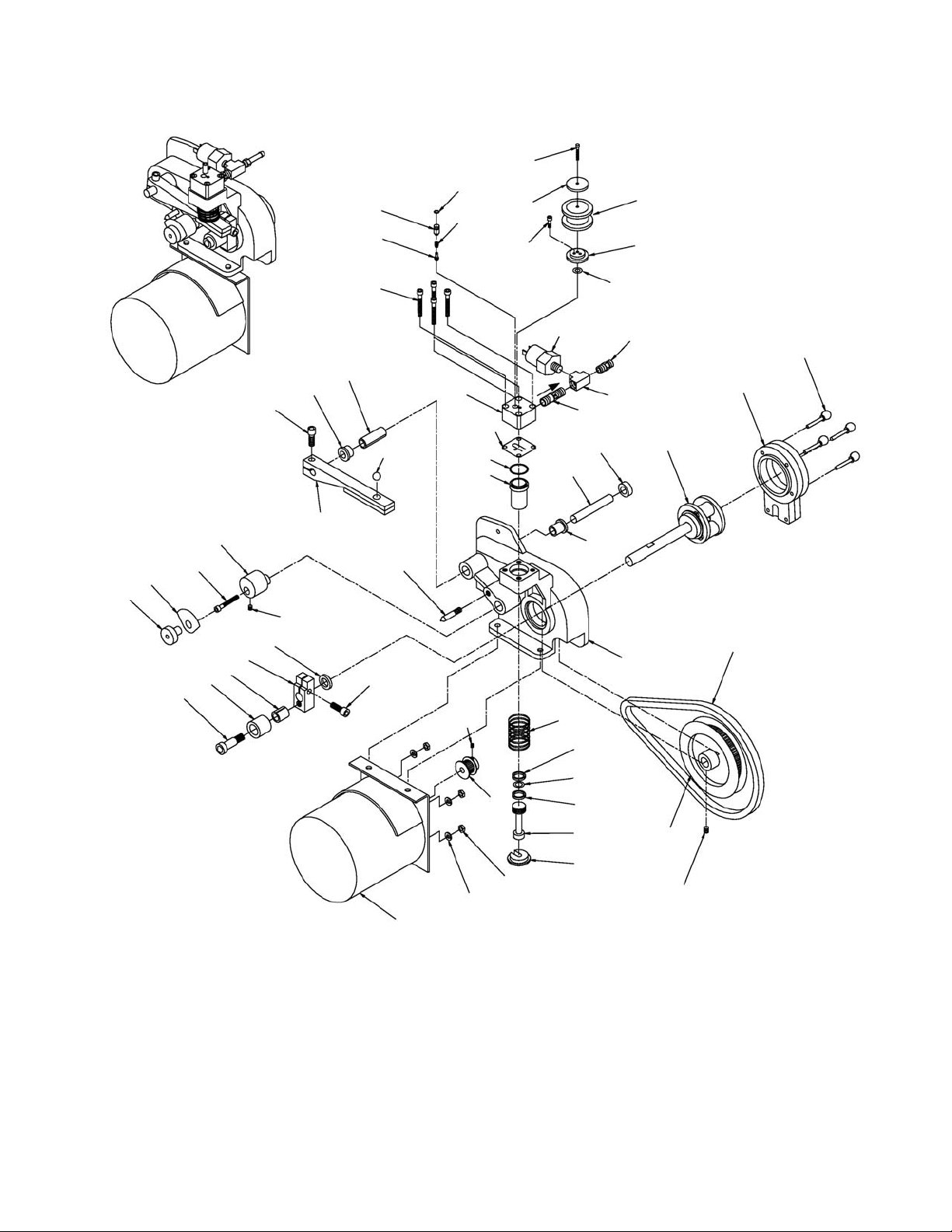
8.7 PUMP PARTS (CONTINUED)
59
Page 68

8.8 CAB INTERIOR
Part Number Description Quantity
128311 Hinge - Door (Top & Bottom) (Cab) 2
128312 Mix Container Holder Assembly w/Rollers (Cab) 1
162048 Blade - Fan (Evaporator) (Cab) 1
266018 Clip - “J” (Hose Holder) (Cab) 1
266076 Clip - Bag In Box (Cab) 2
284095 Evaporator (Cab) 1
396449 Gasket - Door (Cab) 1
522307-SV Motor - Fan (Evaporator Assembly) (Cab) 1
672724 Sensor - Capacitive (Cab) 1
719123-SV Switch - Pushbutton Door (Cab) 1
736084 Thermometer (Cab) 1
2183763 Mix Container Drawer (Cab) 1
2183765 Handle - Door (Cab) 1
2187296 Guard - Fan (Cab) 1
2187306 Door Assembly - Foamed (Cab) 1
2187931 Switch Kit - Cab Door (Hamlin Reed Switch) (Cab) -
60
Page 69

8.9 HEADER PANEL - ELECTRICAL
688026
295017
765214
718537
202198
521686-230
718532
744142
Part Number Description Quantity
202198 Switch - Blender Power & Reset (SU412) 1
229116 Cable - Phone (control Board to Display Board) 1
230638 Capacitor - Start (#282047 Compressor) 1
231057 Capacitor - Run (#282047 Compressor) 1
295017 Contactor (45CG20AG) (Drive Motor / Compressor / Cab) 2
521686-230 Program Board - IntelliTec (208V / 230V) 1
618180 Relay (Compressor) 1
688026 Blender Outlet Socket (SU412) 1
718532 Switch - Toggle (Freezing Cylinder On-Off ) 1
718537 Switch - Limit (Door Interlock) & (SU412 - Blender Activation) 2
744142 Transformer 1
765214 Varistor Harness 4
618180
231057
230638
61
Page 70

8.10 LEFT HAND SIDE
284085
342004
162077
522291
614232
598245
493042
231101
762454
152237
763422
458003
598072
522858-SV
762978
Part Number Description Quantity
152237 Belt - Gripnotch (AX35) (50 Hz) / (60 Hz Ser. #28561 Plus) 1
152245 Belt - V (4L350) (60 Hz) (Ser. #0- #28560) 1
162077 Blade - Fan (Air-Cooled Condenser) 1
231078 Capacitor - Run (#522858 Motor) 1
231095 Capacitor - Start (#522858 Motor) 1
231101 Cap Tube Only 1
284085 Condenser (Air-Cooled) 1
284104 Condenser (Water-Cooled) 1
342004 Drier (Liquid Line) 1
368325 Filter - Air (Condenser) 1
458003 Indicator - Liquid Line 1
493042 Flasher - Indicator Light (Cab On - Off) 1
522291 Motor - Fan (Air-Cooled Condenser) 1
522858-SV Motor - Drive (60 Hz) 1
522859 Motor - Drive (50 Hz) 598072 Pulley - Drive Motor (60 Hz) (Ser. #0- #28560) 598245 Pulley - Speed Reducer (60 Hz) (Ser. #0- #28560) 598296 Pulley - Speed Reducer (60 Hz) (Ser. #28561 Plus) 1
598540 Pulley - Drive Motor (60 Hz) (Ser. #28561 Plus) 1
614232 Speed Reducer 1
762454 Valve - Expansion 1
762978 Valve - EPR (Cab) 1
763422 Valve - Solenoid (Liquid Line) (Has 2) 2
763181 Valve - Water 1
62
Page 71

8.11 RIGHT HAND SIDE
2202439-SV
272065
763423
762275
762454
762329
762457-SV
Part Number Description Quantity
272065 Valve Coil - Solenoid (#763723 Valve) 1
762275 Valve - Magna Check (Cab) 1
762329 Valve - Magna Check (EPR) (Cab) 1
762454 Valve - Expansion 1
762457-SV Valve - Expansion (w/Orifi ce) (Cab) 1
763422 Valve - Solenoid (Liquid Line) (Has 2) 2
763423 Valve - Solenoid (Suction Side) (Has 1) 1
763482 Valve Coil - Solenoid (#763422) 2
2202439-SV Evaporator & Auger Kit 1
763482
763422
63
Page 72

8.12 REAR
718794
762359
763017
737039
282047
558004
Part Number Description Quantity
282047 Compressor - 1 PH - 60 Hz (Scroll) (No Capacitors) 1
282059 Compressor - 1 PH - 50 Hz (Scroll) (No Capacitors) 558004 Condensate Pan 1
718794 Switch - High Pressure Cutout 1
737039 Thermostat - Discharge Line 1
762359 Valve Core (Schrader) 763017 Valve - Hot Gas Bypass 1
778027 Wrench - Allen (Cab) 1
64
Page 73

8.13 BRUSHES, DECALS AND LUBRICATION
Part Number Description Quantity
208135 Brush - 4” X 8” X 16” (Barrel) 1
208380 Brush - 1/4” X 3” X 14” 1
208387 Brush - 1/2” X 5” X 24” 1
208465 Brush - 1” X 3-1/2” X 18” 1
208467 Brush - 3/8” X 1” X 5” 1
324014 Decal - Black Arrow on White Back 1
324065 Decal - Water Inlet 1
324103 Decal - Caution Rotating Shaft 1
324106 Decal - Caution Electrical Wiring Materials 1
324107 Decal - Caution Hazardous Moving Parts 1
324125 Decal - Danger Electric Shock Hazard 1
324141 Decal - Caution Rotating Blades 1
324200 Decal - High Pressure Cut-Out 1
324208 Decal - Attention Refrigerant Leak Check 1
324346 Decal - Caution Hazardous Moving Parts 1
324478 Decal - Electrical Box 1
324509 Decal - Cleaning Instructions 1
324566 Decal - Wired According To 1
324584 Decal - Adequate Ventilation 3” 1
324686 Decal - Danger Automatic Start 1
324803 Decal - Domed Stoelting Logo (Large) (Header Panel) 1
324804 Decal - Domed Stoelting Swirl (Header Panel) 1
324825 Decal - Main Freezer Power 1
324826 Decal - Cab Off 1
324827 Decal - Freezing Cylinder 1
324835 Decal - Blender Power On / Off (SU412) 1
324837 Decal - Caution Blender (SU412) 1
508048 Lubricant - Spline (2 oz Squeeze Tube) 1
508135 Petrol Gel - 4 oz Tube 1
513625 Manual Owner’s 1
1177990 Caster Kit - 4” (Set Of 4) -
8.14 STAINLESS STEEL PANELS
Part Number Description Quantity
647653 Screw - Panel (Top, Header) & Cab (Door Handle & Bottom Hinge) 6
647899 Screw - Panel (Side, Rear & Front Shroud) & Cab (Top Hinge) 8
2183610 Panel - Top (Air-Cooled) 1
2183611 Support - Drip Tray 1
2183760 Panel - R.H. Side 1
2183761 Panel - L.H. Side 1
2183762 Panel - Rear 1
2183774 Panel - Top (Water-Cooled) 1
65
Page 74
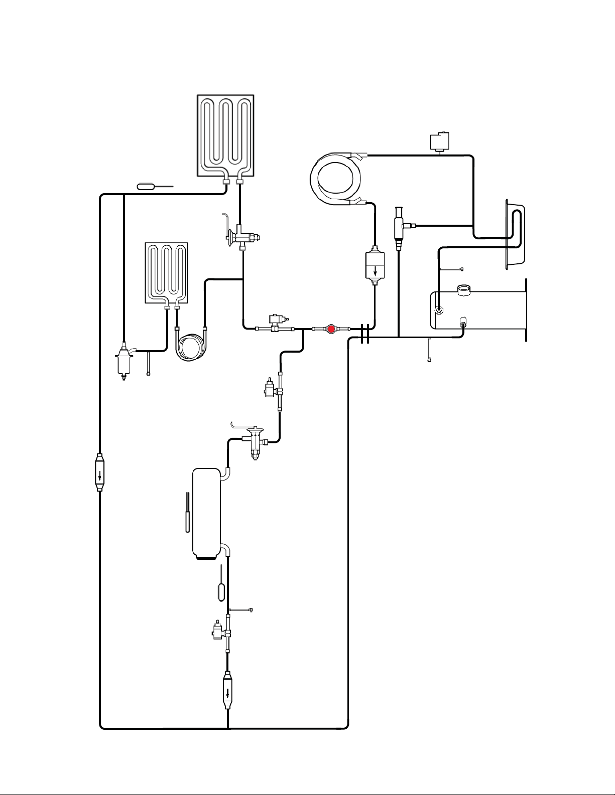
!" #
$
%
$
%
&%
!''(
)(* #
&+
!,- #
.
/
+
%0!1231- #
45
! #
&
5
!" #
!" #
8.15 REFRIGERATION DIAGRAM AND WIRING DIAGRAM
66
Page 75

67
Page 76

68
Page 77

DOMESTIC WARRANTY
(Including Mexico)
SOFT SERVE / SHAKE EQUIPMENT
1. Scope:
PW Stoelting, L.L.C. (“Stoelting”) warrants to the first user (the “Buyer”) that the freezing cylinders,
hoppers, compressors, drive motors, speed reducers, and augers of Stoelting soft serve / shake
equipment will be free from defects in materials and workmanship under normal use and proper
maintenance appearing within five (5) years, and that all other components of such equipment
manufactured by Stoelting will be free from defects in material and workmanship under normal use
and proper maintenance appearing within twelve (12) months after the date that such equipment is
originally installed.
2. Disclaimer of Other Warranties:
THIS WARRANTY IS EXCLUSIVE; AND STOELTING HEREBY DISCLAIMS ANY
IMPLIED WARRANTY OF MERCHANTABILITY OR FITNESS FOR PARTICULAR
PURPOSE.
3. Remedies:
Stoelting’s sole obligations, and Buyer’s sole remedies, for any breach of this warranty shall be the
repair or (at Stoelting’s option) replacement of the affected component at Stoelting’s plant in Kiel,
Wisconsin, or (again, at Stoelting’s option) refund of the purchase price of the affected equipment,
and, during the first twelve (12) months of the warranty period, deinstallation/reinstallation of the
affected component from/into the equipment. Those obligations/remedies are subject to the
conditions that Buyer (a) signs and returns to Stoelting, upon installation, the Start-Up and Training
Checklist for the affected equipment, (b) gives Stoelting prompt written notice of any claimed breach
of warranty within the applicable warranty period, and (c) delivers the affected equipment to Stoelting
or its designated service location, in its original packaging/crating, also within that period. Buyer shall
bear the cost and risk of shipping to and from Stoelting’s plant or designated service location.
4. Exclusions and Limitations:
This warranty does not extend to parts, sometimes called “wear parts”, which are generally expected
to deteriorate and to require replacement as equipment is used, including as examples but not
intended to be limited to o-rings, auger flights, auger seals, auger support bushings, and drive belts.
All such parts are sold
AS IS.
Further, Stoelting shall not be responsible to provide any remedy under this warranty with respect to
any component that fails by reason of negligence, abnormal use, misuse or abuse, use with parts or
equipment not manufactured or supplied by Stoelting, or damage in transit.
THE REMEDIES SET FORTH IN THIS WARRANTY SHALL BE THE SOLE LIABILITY
STOELTING AND THE EXCLUSIVE REMEDY OF BUYER WITH RESPECT TO
EQUIPMENT SUPPLIED BY STOELTING; AND IN NO EVENT SHALL STOELTING
BE LIABLE FOR ANY INCIDENTAL OR CONSEQUENTIAL DAMAGES, WHETHER
FOR BREACH OF WARRANTY OR OTHER CONTRACT BREACH, NEGLIGENCE OR
OTHER TORT, OR ON ANY STRICT LIABILITY THEORY.
SFWARR-013
Revision 04
Page 1 of 1
 Loading...