

Stoelting U3-02 Service Manual

U3-02 Mix Pump
Owner's/Service Manual
Manual No. 513557


Need Parts or Service?
We stock the parts you need.
Our Technicians are factory
trained and are certified in the
Stoelting Technicare program.
CALL
Distributor: _________________________
Phone No.: _________________________
(fill in or affix label)
Model No.: _______________________
Serial No.: _______________________
Purchase Date: ____________________
Start-Up Date:____________________


INTRODUCTION
U3-02 MIX PUMP - OWNER'S / SERVICE MANUAL
This manual provides basic information about the mix pump and its components. Instructions and suggestions are
given covering its basic operation and care.
The illustrations and specifications are not binding in detail. We reserve the right to make changes at any time without
notice to mix pump or components without incurring any obligation to equip same on mix pump built prior to date of
change.
DO NOT ATTEMPT to operate the mix pump until instructions and safety precautions in the manual are read completely
and thoroughly understood. The mix pump should be operated only by qualified personnel. If problems develop or
questions arise in connection with the installation, operation, or servicing of the mix pump, contact your local distributor
or the company at the following location:
STOELTING, LLC Ph: 920-894-2293
502 HWY. 67
KIEL, WISCONSIN 53042-1600 Fax: 920-894-7029


A Few Words About Safety
Safety Information
Read and understand the entire manual before
operating or maintaining Stoelting equipment.
This Owner's Manual provides the operator with
information for the safe operation and maintenance of
Stoelting equipment. As with any machine, there are
hazards associated with their operation. For this
reason safety is emphasized throughout the manual.
T o highlight specific safety information, the following
safety definitions are provided to assist the reader .
The purpose of safety symbols is to attract your
attention to possible dangers. The safety symbols,
and their explanations, deserve your careful attention
and understanding. The safety warnings do not by
themselves eliminate any danger . The instructions or
warnings they give are not substitutes for proper
accident prevention measures.
If you need to replace a part, use genuine Stoelting
parts with the correct part number or an equivalent
part. We strongly recommend that you do not use
replacement parts of inferior quality .
Safety Alert Symbol:
This symbol Indicates danger, warning or caution.
Attention is required in order to avoid serious personal
injury . The message that follows the symbol cont ains
important information about safety .
Signal Word:
Signal words are distinctive words used throughout
this manual that alert the reader to the existence and
relative degree of a hazard.
WARNING
The signal word “WARNING” indicates a potentially
hazardous situation, which, if not avoided, may result
in death or serious injury and equipment/property
damage.
CAUTION
The signal word “CAUTION” indicates a potentially
hazardous situation, which, if not avoided, may result
in minor or moderate injury and equipment/property
damage.
CAUTION
The signal word “CAUTION” not preceded by the safety
alert symbol indicates a potentially hazardous situation, which, if not avoided, may result in equipment/
property damage.
NOTICE
The signal word “NOTICE” indicates information or
procedures that relate directly or indirectly to the
safety or personnel or equipment/property.


TABLE OF CONTENTS
SECTION 1 — INTRODUCTION ............................................................................................................................ 1
1.1 Description ..................................................................................................................................................... 1
1.2 Specifications ................................................................................................................................................. 1
SECTION 2 — INST ALLATION INSTRUCTIONS................................................................................................... 3
2.1 Shipment and Transit ..................................................................................................................................... 3
2.2 National Sanitation Foundation Compliance Requirements............................................................................ 3
2.3 Installation ...................................................................................................................................................... 3
2.4 Mix Pump Check Out ..................................................................................................................................... 5
SECTION 3 — OPERA TION INSTRUCTIONS ....................................................................................................... 7
3.1 Safety Precautions ......................................................................................................................................... 7
3.2 Pump Motor Switch ........................................................................................................................................ 7
3.3 Operation Of U3 Mix Pump............................................................................................................................ 7
3.4 Cleaning......................................................................................................................................................... 8
3.5 Disassembly and Inspection of Removable Parts.......................................................................................... 8
3.6 Sanitizing and Startup.................................................................................................................................... 9
3.7 Cleaning Mix Lines ......................................................................................................................................... 9
SECTION 4 — MAINTENANCE INSTRUCTIONS ............................................................................................... 11
4.1 Overrun Adjustment .......................................................................................................................................11
4.2 Preventative Maintenance ..............................................................................................................................11
SECTION 5 — TROUBLESHOOTING ................................................................................................................ 13
SECTION 6 — REPLACEMENT P ARTS INFORMATION .................................................................................... 15
6.1 How to Order Replacement Parts................................................................................................................. 15
6.2 Parts List and Reference Drawings ............................................................................................................. 15

LIST OF ILLUSTRATIONS
Figure Description Page
1 U3 Pump ................................................................................................................. 1
2 Mix Transfer Line .................................................................................................... 3
A Mix Pump Hose ...................................................................................................... 4
B Pickup Hose ........................................................................................................... 4
C Pickup Hose ........................................................................................................... 4
3 Mix Pump Installation.............................................................................................. 5
D 4-way Tee Connection ............................................................................................. 5
4 Pump Motor Switch................................................................................................. 7
5 Mix Pump Operation ............................................................................................... 8
6 Removing Parts ...................................................................................................... 8
7 Overrun Adjustment................................................................................................ 11
8 Reposition Mix Pump Hose..................................................................................... 12
9 Pump Roller Assembly............................................................................................ 12
10 Pump and Decal Assembly ..................................................................................... 15
Exploded Parts Illustrations..................................................................................... 17-21
Wiring Diagram........................................................................................................ 23
SECTION 1
INTRODUCTION
1.1 DESCRIPTION
The Model U3 Remote Mix Pump is specially designed for
use with Stoelting remote pressurized freezers. Used with
large capacity mix containers located in your bulk storage
cooler, the U3 Pump keeps mix handling to a minimum.
Stoelting’s Model U3 Remote Mix Pump performs three
important functions with precision and reliability. First, it
transfers a continuous supply of mix from your remote
storage container to the freezing cylinder of your freezer quickly, conveniently. Second, the U3 Pump precisely
injects a preset amount of air into the mix, maintaining
overrun to assure maximum profitability. Third, it pressurizes the freezing cylinder, forcing frozen product through
the spigot at the rapid dispense rates needed by high
volume locations.
1.2 SPECIFICATIONS
WEIGHT
24 lbs. (10.89 kg)
DIMENSIONS
Width: 9-3/4" (24.8 cm)
Height: 8-1/2" (21.6 cm)
Depth: 10-1/8" (25.7 cm)
ELECTRICAL
1 phase, 120 volts. Approximately 1.6 total running amps.
Cord and plug attached.
WARRANTY
One year parts.
UL, C-UL Approved, NSF Approved
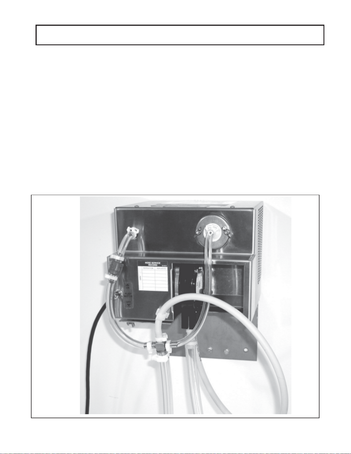
Figure 1
U3 Pump
1
 Loading...