

Stoelting U218 Service Manual

Model U218
SERVICE MANUAL
Manual No. 513637 Rev.1 Nov., 2008


Service Manual
For U218
Stoelting Floor Model Gravity Machine
Frozen Beverage
This manual provides basic information about the machine. Instructions and suggestions are
given covering its operation and care.
The illustrations and specifications are not binding in detail. We reserve the right to make
changes to the machine without notice, and without incurring any obligation to modify or provide new parts for machines built prior to date of change.
DO NOT ATTEMPT to operate the machine until instructions and safety precautions in this
manual are read completely and are thoroughly understood. If problems develop or questions
arise in connection with installation, operation, or servicing of the machine, contact the company at the following location:
STOELTING, LLC Ph: 800-558-5807
502 Hwy. 67
Kiel, WI 53042 Fax: 920-894-7029

A Few Words About Safety
Safety Information
Read and understand the entire manual before
operating or maintaining Stoelting equipment.
This Owner's Manual provides the operator with
information for the safe operation and maintenance of
Stoelting equipment. As with any machine, there are
hazards associated with their operation. For this
reason safety is emphasized throughout the manual.
To highlight specific safety information, the following
safety definitions are provided to assist the reader.
The purpose of safety symbols is to attract your
attention to possible dangers. The safety symbols,
and their explanations, deserve your careful attention
and understanding. The safety warnings do not by
themselves eliminate any danger. The instructions or
warnings they give are not substitutes for proper
accident prevention measures.
If you need to replace a part, use genuine S toelting
parts with the correct part number or an equivalent
part. We strongly recommend that you do not use
replacement parts of inferior quality .
Safety Alert Symbol:
This symbol Indicates danger, warning or caution.
Attention is required in order to avoid serious personal injury . The message that follows the symbol
contains important information about safety .
Signal Word:
Signal words are distinctive words used throughout
this manual that alert the reader to the existence and
relative degree of a hazard.
WARNING
The signal word “WARNING” indicates a potentially
hazardous situation, which, if not avoided, may result
in death or serious injury and equipment/property
damage.
CAUTION
The signal word “CAUTION” indicates a potentially
hazardous situation, which, if not avoided, may result
in minor or moderate injury and equipment/property
damage.
CAUTION
The signal word “CAUTION” not preceded by the
safety alert symbol indicates a potentially hazardous
situation, which, if not avoided, may result in equipment/property damage.
NOTICE
The signal word “NOTICE” indicates information or
procedures that relate directly or indirectly to the
safety or personnel or equipment/property .

TABLE OF
CONTENTS
Section Description Page
1 Description and Specifications
1.1 Description.................................................................................................1
1.2 Specifications............................................................................................. 1
1.3 Modes of Normal Operation.......................................................................2
1.4 Operation During an Error Mode................................................................3
2 Installation Instructions
2.1 Safety Precautions.....................................................................................5
2.2 Shipment and Transit.................................................................................5
2.3 Machine Installation ...................................................................................5
3 Initial Set-Up and Operation
3.1 Operator”s Safety Precautions...................................................................7
3.2 Operating Controls and Indicators .............................................................7
3.3 Sanitizing ...................................................................................................8
3.4 Freeze Down and Operation ......................................................................9
3.5 Removing Mix From Machine ....................................................................9
3.6 Cleaning the Machine ................................................................................9
3.7 Disassembly of Machine Parts...................................................................10
3.8 Cleaning the Machine Parts.......................................................................11
3.9 Sanitize Machine and Machine Parts .........................................................11
3.10 Assembly of Machine.................................................................................12
3.11 Routine Cleaning .......................................................................................12
4 Maintenance and Adjustments
4.1 Machine Adjustment ..................................................................................13
4.2 Product Consistency Adjustment ...............................................................13
4.3 Continuous Drive Mode .............................................................................13
4.4 Drive Belt Tension Adjustment...................................................................13
4.5 Preventative Maintenance..........................................................................13
4.6 Extended Storage ......................................................................................14

Section Description Page
5 Refrigeration System
5.1 Refrigeration System .................................................................................15
5.2 Refrigerant Recovery and Evacuation........................................................15
5.3 Refrigerant Charging..................................................................................16
5.4 Compressor...............................................................................................16
5.5 Condenser .................................................................................................17
5.6 Valves........................................................................................................18
A. Thermostatic Expansion Valve (TXV)..................................................................18
B. High Pressure Cutout .......................................................................................... 19
C. Evaporator Pressure Regulator (EPR)................................................................19
D. Water Vavle (Water-Cooled Models Only)..........................................................20
5.7 Capillary Tube............................................................................................21
5.8 Filter Drier..................................................................................................21
6 Electrical and Mechanical Control Systems
6.1 Control Board.............................................................................................23
6.2 Contactor ...................................................................................................23
6.3 Drive Motor ................................................................................................24
6.4 Capacitors .................................................................................................25
6.5 Gearbox.....................................................................................................25
6.6 Condenser Fan Motor (Air-Cooled Models Onlys) .....................................26
6.7 Switches ....................................................................................................26
A. Spigot Switch.......................................................................................................26
B. Torque Switch......................................................................................................26
7 Troubleshooting
7.1 Light Indicators ..........................................................................................27
7.2 Troubleshooting .........................................................................................27
8 Replacement Parts
8.1 Decals & Lubrication ..................................................................................29
8.2 Accessories, Panels & Screws ..................................................................29
8.3 Auger Shaft & Faceplate Parts...................................................................30
8.4 Hopper Parts..............................................................................................32
8.5 Machine Front & Spigot Switch Assembly..................................................33
8.6 Left Side (Air-Cooled Shown).....................................................................34
8.7 Right Side (Water-Cooled Shown) .............................................................35
8.8 Machine Back (Water-Cooled Shown).......................................................36
8.9 Refrigeration & Wiring Diagram .................................................................37
8.10 Autofill Options...........................................................................................39
SECTION 1
DESCRIPTION AND SPECIFICATIONS
1.1 DESCRIPTION
The Stoelting U218 machine is available as gravity fed or
with an optional autofill kit. It is equipped with fully automatic controls to provide a uniform product. The U218
machine will operate with almost any type of frozen beverage mix. This manual is designed to help qualified service
personnel and operators with the installation, operation
and maintenance of the Stoelting U218 machine.
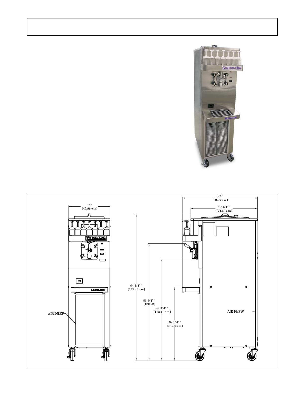
1.2 SPECIFICATIONS
Figure 1-1 Model U218
Figure 1-2 Model U218 Dimensions
1

1.2 SPECIFICATIONS - CONTINUED
Dimensio ns
Machine
Model U 218
wit h c ra te
width
height
depth
18-1/4'' (46,4 cm)
64-1/2'' (163,8 cm)
33'' (83,8 cm )
Weight
Elect r i c al
1 Phase, 208-2 40 VAC, 60Hz
running amps
con nection t ype
NEM A6- 20P power cord provided
Compressor
Driv e M ot or
Ai r Flow
Plumbi ng Fit tings
Air cooled u nits require 3" (7,6 cm ) air space a t fr on t an d ba ck.
Wat er coo led un its r equ ire 3/ 8" N .P. T . w at er and drain f ittin gs.
Hopper Volum e
Freezing Cylinder
Volum e
1.3 MODES OF NORMAL OPERATION
Following is an explanation of the normal operation modes
on the U218 (Refer to Figure 1-3).
NOTE
The following modes of operation are for the latest
versions of the control boards (521696.2 and
521696.1 Rev72). The older version of the control
has the following differences:
• There is no slush mode with continuous drive.
• There is no consistency check during the pre stir
in slush mode and the pre stir is 3 seconds.
• The control runs strictly on timers during an error
mode, and the cycle time during a drive motor error
is 7 minutes off/55 seconds on.
NOTE
Slush mode has two options: normal and continuous drive. The normal mode saves energy. Continuous drive is used in rare situations where very
thin slush is required. With the continuous drive option selected, the drive motor will run at all times,
including standby. To change the control between
the two options, refer to section 4.3.
A. PRE STIR
When the CLEAN-OFF-ON is moved into the ON position
or when the spigot is opened, the drive motor will start a 4second pre stir. During the pre stir, a consistency check
will determine if the freezing cycle will begin.
25'' (63,5 cm)
66'' (167,6 cm )
51'' (129,5 cm )
410 lbs (18 5,9 kg)315 lbs (142,8 kg)
approximatel y 12A
11,000 Btu/ h r
1/2 h p
7 gallon (26,50 liters)
2 gall on ( 8 qu ar t) , 7, 57 l iters
B. FREEZING CYCLE
After the pre stir, a freezing cycle begins. The freezing
cycle continues until the torque rod closes the torque
switch and keeps the switch closed for 3 seconds. If
product consistency is not met within 22 minutes, the
machine will operate in the compressor time out mode
(See Section 1.4).
NOTE
If the spigot is pulled during a freezing cycle, the
22-minute timer will restart.
C. POST STIR
After the freezing cycle ends, the drive motor will continue
to run for an 18 second post stir. The post stir ensures the
product does not freeze to the cylinder. If the spigot is
opened during the post stir, the machine will check consistency. If the product is at consistency, the machine will
move into standby. If the product is not at consistency, the
machine will start a freezing cycle.
D. STANDBY
After the post stir, the machine will be in standby. It will
remain in standby for 7 minutes or until the spigot is
opened.
E. DEFROST MODE
If the spigot is not opened for 3 hours, defrost mode will
begin. The auger will run for 90 seconds every 7 minutes
and the diagnostic light will remain lit. The compressor
does not operate during defrost mode. After 5.5 hours or
if the spigot is opened, normal operation mode will begin.
2
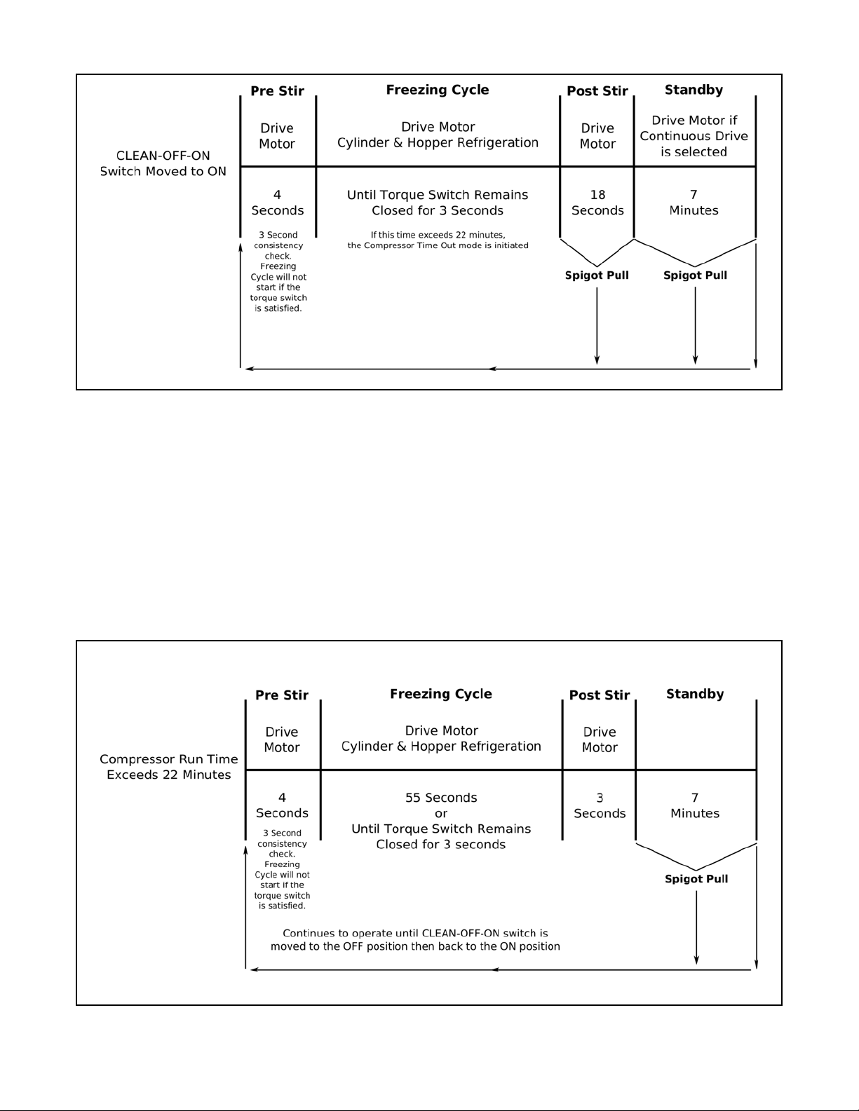
Figure 1-3 Modes of Normal Operation
F. CLEAN MODE
When the CLEAN-OFF-ON switch is in the CLEAN position, the drive motor starts and will run for 20 minutes. After
the 20 minutes expire, the drive motor will stop and the
diagnostic light will flash three times every 4 seconds. It will
continue to flash until the CLEAN-OFF-ON switch is
moved out of the CLEAN position.
1.4 OPERATION DURING AN ERROR MODE
A. COMPRESSOR TIME OUT MODE
If the freezing cycle exceeds 22 minutes, the machine will
operate on timers. The diagnostic light will flash once
every 4 seconds (Refer to Figure 1-4).
Figure 1-4 Compressor Time Out Mode
3
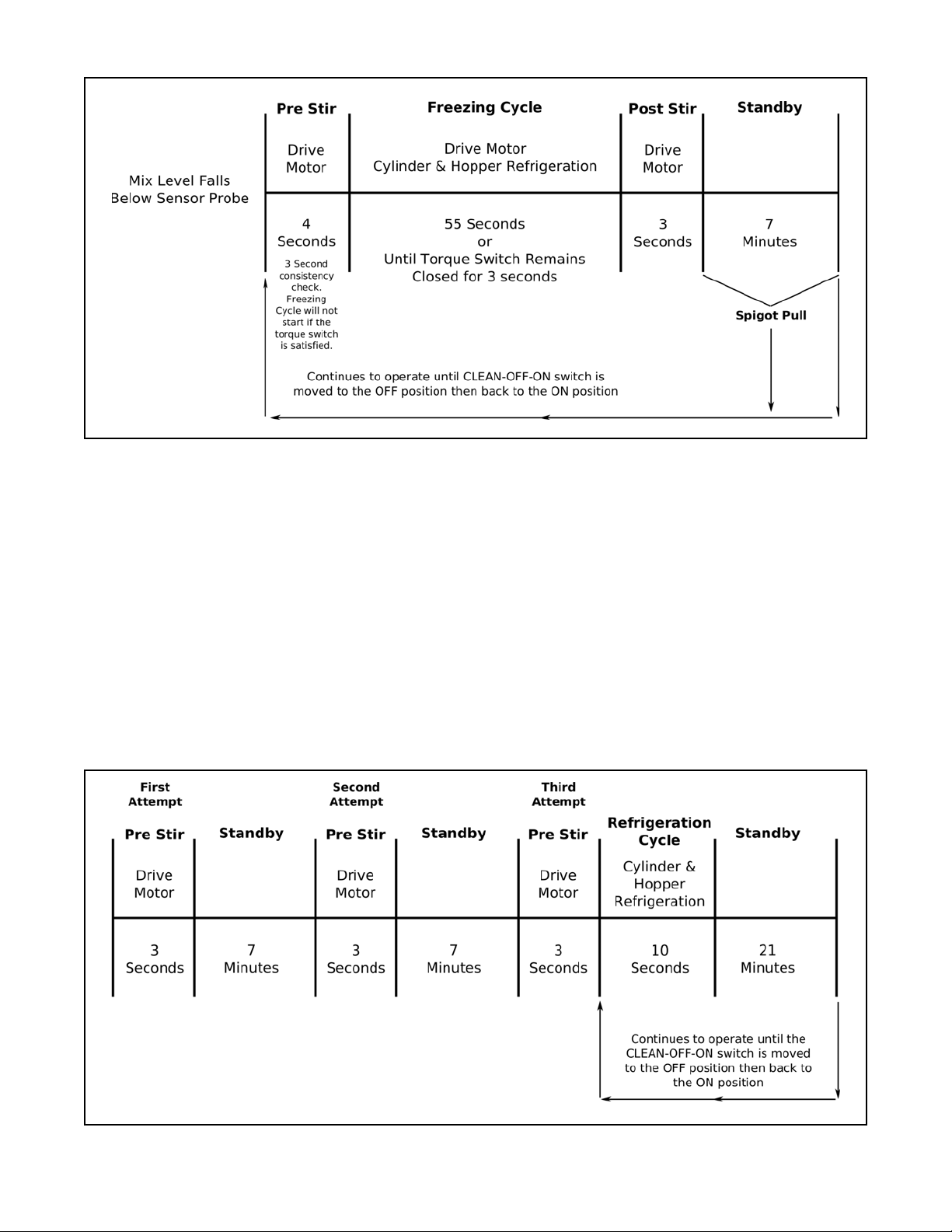
Figure 1-5 Low Mix Mode
B. LOW MIX MODE
If the mix level falls below the long sensor probe in the
hopper, the machine will operate on timers. The ADD MIX
light will flash. The machine will continue to operate on
timers until the mix level in the hopper is above the sensor
probe (Refer to Figure 1-5).
NOTE
The hopper has two probes. The longer probe monitors mix level in the hopper. The shorter probe shuts
off the optional autofill system if installed.
C. DRIVE MOTOR ERROR MODE
If the control does not sense current from the drive motor
during a pre stir, the machine will go into standby mode for
7 minutes. After standby, the control will repeat the pre stir
and attempt to sense drive motor current. After the third
pre stir without sensing drive motor current, the machine
will operate on timers and the diagnostic light will flash
twice every four seconds (Refer to Figure 1-6). The
attempts to sense the drive motor current can be substituted by pulling the spigot.
Figure 1-6 Drive Motor Error Mode
4
SECTION 2
INSTALLATION INSTRUCTIONS
2.1 SAFETY PRECAUTIONS
Do not attempt to operate the machine until the safety
precautions and operating instructions in this manual are
read completely and are thoroughly understood.
Take notice of all warning labels on the machine. The
labels have been put there to help maintain a safe working
environment. The labels have been designed to withstand
washing and cleaning. All labels must remain legible for
the life of the machine. Labels should be checked periodically to be sure they can be recognized as warning labels.
If danger, warning or caution labels are needed, indicate
the part number, type of label, location of label, and
quantity required along with your address and mail to:
STOELTING, LLC
A TTENTION: Customer Service
502 Hwy . 67
Kiel, Wisconsin 53042
2.2 SHIPMENT AND TRANSIT
The machine has been assembled, operated and inspected at the factory. Upon arrival at the final destination,
the entire machine must be checked for any damage
which may have occurred during transit.
With the method of packaging used, the machine should
arrive in excellent condition. THE CARRIER IS RESPONSIBLE FOR ALL DAMAGE IN TRANSIT, WHETHER
VISIBLE OR CONCEALED. Do not pay the freight bill until
the machine has been checked for damage. Have the
carrier note any visible damage on the freight bill. If
concealed damage and/or shortage is found later, advise
the carrier within 10 days and request inspection. The
customer must place claim for damages and/or shortages
in shipment with the carrier. Stoelting, LLC cannot make
any claims against the carrier.
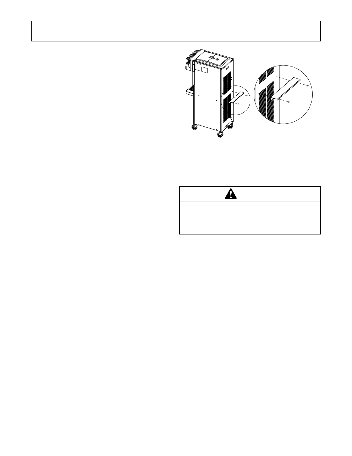
2.3 MACHINE INSTALLATION
Installation of the machine involves moving the machine
close to its permanent location, removing all crating,
setting in place, assembling parts, and cleaning.
A. Uncrate the machine.
B. Accurate leveling is necessary for correct drainage
of machine barrel and to insure correct overrun.
Place a bubble level on top of the machine at each
corner to check for level condition. If adjustment
is necessary, level the machine by turning the nut
of each caster in or out.
C. Correct ventilation is required. Install the rear air
baffle to provide the 3” clearance at the front and
back (Refer to Figure 2-1). Remove the rear panel
screws and use them to attach the baffle. The
machine can be placed side-by-side next to other
equipment.
Figure 2-1 Rear Air Baffle
D. Place the CLEAN-ON-OFF switch in the OFF
position.
WARNING
Do not alter or deform electrical plug in any way.
Altering the plug to fit into an outlet of different configuration may cause fire, risk of electrical shock,
product damage and will void warranty .
E. Connect the power cord to the proper power
supply. The plug on the U218 is designed for 208240 volt / 20 amp duty. Check the nameplate on
your machine for proper supply. The unit must be
connected to a properly grounded receptacle.
The electrical cord furnished as part of the machine
has a three prong grounding type plug. The use of
an extension cord is not recommended, if
necessary use one with a size 12 gauge or heavier
with ground wire. Do not use an adapter to
circumvent the grounding requirement.
5

6
SECTION 3
INITIAL SET-UP AND OPERATION
3.1 OPERATOR’S SAFETY PRECAUTIONS
SAFE OPERATION IS NO ACCIDENT; observe these
rules:
A. Know the machine. Read and understand the
Operating Instructions.
B. Notice all warning labels on the machine.
C. Wear proper clothing. Avoid loose fitting garments,
and remove watches, rings or jewelry that could
cause a serious accident.
D. Maintain a clean work area. Avoid accidents by
cleaning up the area and keeping it clean.
E. Stay alert at all times. Know which switch, push
button or control you are about to use and what
effect it is going to have.
F. Disconnect electrical cord for maintenance. Never
attempt to repair or perform maintenance on the
machine until the main electrical power has been
disconnected.
G. Do not operate under unsafe operating conditions.
Never operate the machine if unusual or excessive
noise or vibration occurs.
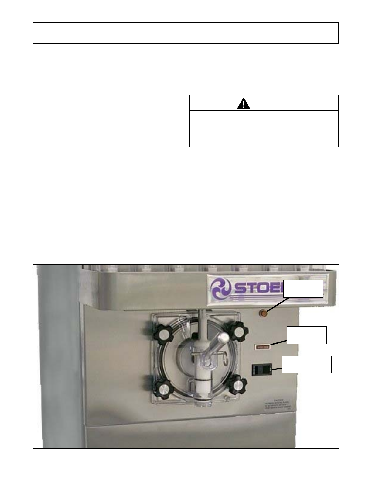
3.2 OPERATING CONTROLS AND INDICATORS
Before operating the machine, it is required that the
operator know the function of each operating control.
Refer to Figure 3-1 for the location of the operating
controls on the machine.
WARNING
High voltage will shock, burn or cause death. The
OFF-ON switch must be placed in the OFF position
prior to disassembling for cleaning or servicing. Do
not operate machine with cabinet panels removed.
A. Spigot Switch
The spigot switch will automatically start the auger
drive and refrigeration systems when the spigot is
opened to dispense product. When the spigot is
closed, the drive motor and compressor will remain
on until the product in the freezing cylinder reaches
the proper consistency.
B. CLEAN-OFF-ON Switch
The CLEAN-OFF-ON switch is used to supply
power to the control circuit. When the switch is in
the OFF (middle) position, power will not be
supplied to the control board or refrigeration
Figure 3-1 Machine Controls
7
Diagnostic
Light
Add Mix
Indicator
Clean/Off/On
Switch
system. When the switch is in the ON position, the
machine will operate in the freezing mode. When
the switch is in the CLEAN position, all refrigeration
will stop and the auger will start rotating.
C. ADD MIX Light
The ADD MIX light will flash to alert the operator
to a low mix condition. It does so by monitoring the
mix level in the hopper. When the ADD MIX light
is flashing, refill hopper immediately.
NOTE
Failure to refill hopper immediately may result in
operational problems.
D. Diagnostic Light
The Diagnostic Light will flash if an error occurs.
The light will flash once if there is a compressor
error. There will be two quick flashes if there is an
auger error. And there will be three quick flashes
if the machine is left in clean mode for more than
20 minutes. Refer to the troubleshooting section
for details.
E. Consistency Adjustment Screw
The Consistency Adjustment Screw increases or
decreases product consistency. A tension spring
is connected to the screw and changes the amount
of torque needed to complete a refrigeration cycle.
Turn the screw clockwise to increase consistency
or counterclockwise to decrease consistency.
F. Front Door Safety Switch
The front door safety switch prevents the auger
from turning when the front door is removed. The
switch is open when the door is not in place and
closed when the door is properly installed.
G. Autofill Kit - Optional (Part 2187317)
The autofill kit is used with a pump to keep the
hopper filled. The autofill kit is for use with non-
potentially hazardous food substances; non-dairy.
Refer to Section 8 for Autofill options.
Mix sanitizer according to manufacturer’s instructions to
provide a 100 parts per million strength solution. Mix
sanitizer in quantities of no less than 2 gallons (7.5 liters)
of 90° to 110°F (32° to 43°C) water. Allow sanitizer to
contact the surfaces to be sanitized for 5 minutes. Any
sanitizer must be used only in accordance with the
manufacturer’s instructions.
In general, sanitizing may be conducted as follows:
CAUTION
Do not allow sanitizer to remain in contact with stainless steel machine parts for prolonged periods. Prolonged contact of sanitizer with machine may cause
corrosion of stainless steel parts.
A. Prepare Stera-Sheen Green Label Sanitizer or
equivalent according to manufacturer’s
instructions to provide a 100 ppm strength solution.
Mix the sanitizer in quantities of no less than 2
gallons of 90° to 110°F (32° to 43°C) water. Check
the strength of the sanitizing solution. Use a
chlorine test strip and color chart to make sure the
solution has 100 ppm. Any sanitizer must be used
only in accordance with the manufacturer’s
instructions.
B. Pour the sanitizing solution into the hopper and
place the switch in the CLEAN position. Check for
leaks. Place the switch in the CLEAN position.
Check for leaks.
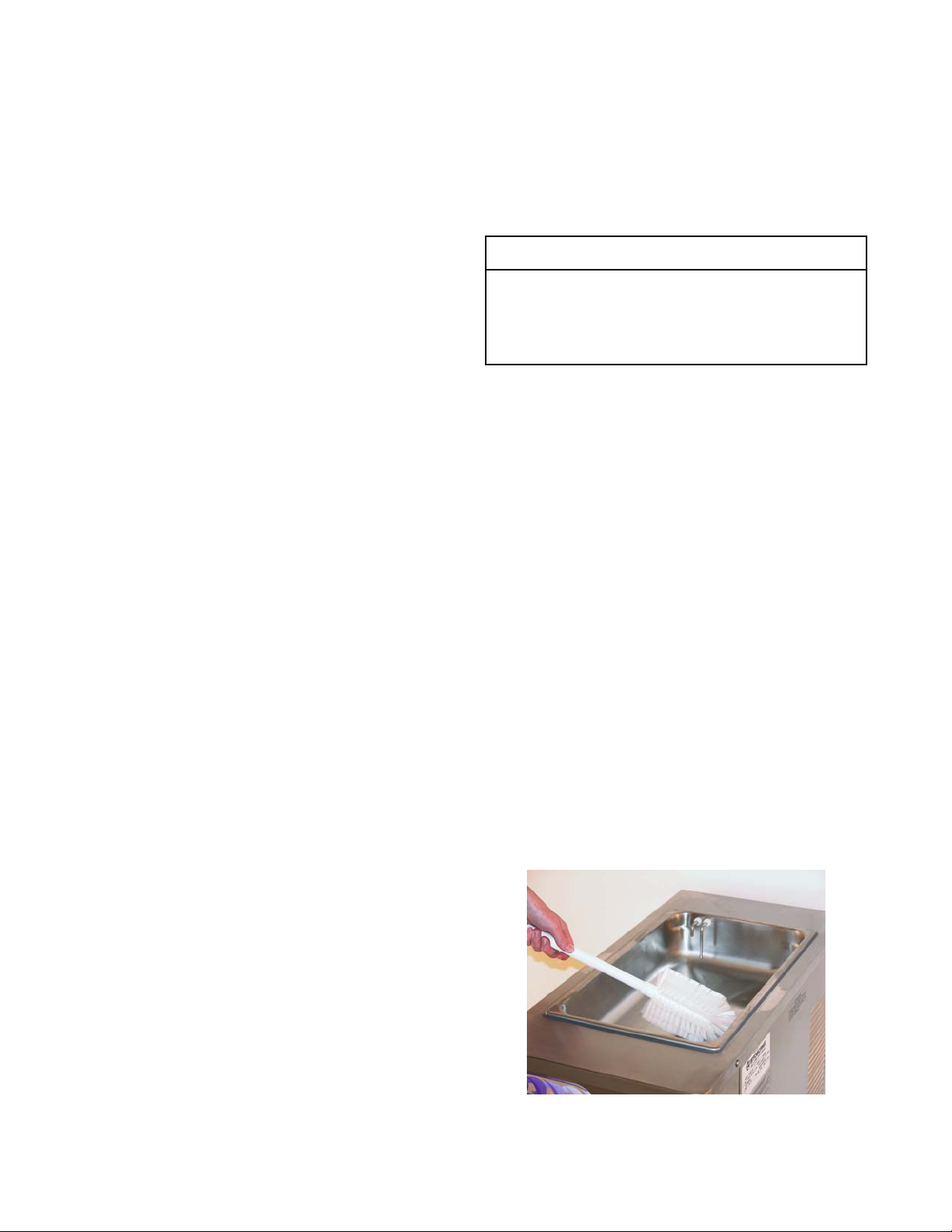
C. Clean the sides of the hopper and the underside
of the hopper cover using a soft bristle brush
dipped in the sanitizing solution (Refer to Figure 3-
2).
D. After five minutes, place a bucket under the spigot
and open spigot to drain most sanitizing solution.
Leave a small amount of the sanitizing solution in
the freezing cylinder. Place the switch in the OFF
(middle) position.
3.3 SANITIZING
Sanitizing must be done after the machine is cleaned and
just before the hopper is filled with mix. Sanitizing the night
before is not effective. However, you should always clean
the machine and parts after each use.
The United States Department of Agriculture and
the Food and Drug Administration require that all
cleaning and sanitizing solutions used with food processing equipment be certified for this use.
When sanitizing the machine, refer to local sanitary regulations for applicable codes and recommended sanitizing
products and procedures. The frequency of sanitizing
must comply with local health regulations.
Figure 3-2 Brush Hopper
8
 Loading...