

Page 1

Model SU444I2
OPERATORS MANUAL
Manual No. 513684 Rev.1
Page 2

Page 3

This manual provides basic information about the machine. Instructions and suggestions are
given covering its operation and care.
The illustrations and specifi cations are not binding in detail. We reserve the right to make
changes to the machine without notice, and without incurring any obligation to modify or provide new parts for machines built prior to date of change.
DO NOT ATTEMPT to operate the machine until instructions and safety precautions in this
manual are read completely and are thoroughly understood. If problems develop or questions
arise in connection with installation, operation, or servicing of the machine, contact Stoelting.
stoeltingfoodservice.com
Stoelting Foodservice Equipment
502 Highway 67
Kiel, WI 53042-1600
U.S.A.
Main Tel: 800.558.5807
Fax: 920.894.7029
Customer Service: 888.429.5920
Fax: 800.545.0662
Email: foodservice@stoelting.com
© 2014 PW Stoelting, LLC
Page 4

A Few Words About Safety
Safety Information
Read and understand the entire manual before
operating or maintaining Stoelting equipment.
This manual provides the operator with information
for the safe operation and maintenance of Stoelting
equipment. As with any machine, there are hazards
associated with their operation. For this reason safety
is emphasized throughout the manual. To highlight
specifi c safety information, the following safety defi ni-
tions are provided to assist the reader.
The purpose of safety symbols is to attract your attention to possible dangers. The safety symbols, and
their explanations, deserve your careful attention
and understanding. The safety warnings do not by
themselves eliminate any danger. The instructions
or warnings they give are not substitutes for proper
accident prevention measures.
If you need to replace a part, use genuine Stoelting
parts with the correct part number or an equivalent
part. We strongly recommend that you do not use
replacement parts of inferior quality.
Safety Alert Symbol:
This symbol Indicates danger, warning or caution.
Attention is required in order to avoid serious personal injury. The message that follows the symbol
contains important information about safety.
Signal Word:
Signal words are distinctive words used throughout
this manual that alert the reader to the existence and
relative degree of a hazard.
WARNING
The signal word “WARNING” indicates a potentially
hazardous situation, which, if not avoided, may result
in death or serious injury and equipment/property
damage.
CAUTION
The signal word “CAUTION” indicates a potentially
hazardous situation, which, if not avoided, may result
in minor or moderate injury and equipment/property
damage.
CAUTION
The signal word “CAUTION” not preceded by the
safety alert symbol indicates a potentially hazardous
situation, which, if not avoided, may result in equipment/property damage.
NOTE (or NOTICE)
The signal word “NOTICE” indicates information or
procedures that relate directly or indirectly to the
safety of personnel or equipment/property.
Page 5

TABLE OF
CONTENTS
Section Description Page
1 Description and Specifi cations
1.1 Description ..................................................................................................1
1.2 Specifi cations .............................................................................................2
2 Installation Instructions
2.1 Safety Precautions .....................................................................................3
2.2 Shipment and Transit ..................................................................................3
2.3 Machine Installation ....................................................................................3
2.4 Installing Wiring ..........................................................................................3
2.5 Check Blender Rotation ..............................................................................4
2.6 Mix Pump ....................................................................................................4
2.7 IntelliTec2™ Setup ......................................................................................6
3 Initial Set-Up and Operation
3.1 Operator’s Safety Precautions ...................................................................9
3.2 Operating Controls and Indicators ..............................................................9
3.3 Disassembly of Left Side ............................................................................10
3.4 Disassembly of Right Side ..........................................................................11
3.5 Cleaning Disassembled Parts ....................................................................12
3.6 Sanitizing Parts ...........................................................................................12
3.7 Cleaning the Machine .................................................................................12
3.8 Assembling the Left Side ............................................................................12
3.9 Assembling the Right Side .........................................................................13
3.10 Sanitizing ....................................................................................................14
3.11 Normal Freeze Down and Operation ..........................................................15
3.12 Mix Information ...........................................................................................15
3.13 Operation of Mix Pump ...............................................................................15
3.14 Mix Pump Cleaning ....................................................................................16
3.15 Disassembly and Inspection Of Removable Parts .....................................16
4 Maintenance and Adjustments
4.1 Overrun Adjustment ....................................................................................19
4.2 Mix Pump Hose Reposition ........................................................................19
4.3 Mix Pump Hose Replacement ....................................................................20
4.4 Fine Consistency Adjustment .....................................................................20
4.5 Drive Belt Tension Adjustment ....................................................................21
4.6 Condenser Cleaning (Air-Cooled Machines) ..............................................21
4.7 Preventative Maintenance ..........................................................................21
4.8 Extended Storage .......................................................................................21
Page 6

Section Description Page
5 Troubleshooting
5.1 Error Codes ................................................................................................23
5.2 Troubleshooting - Error Codes ...................................................................23
5.3 Troubleshooting - Machine .........................................................................25
5.4 Troubleshooting - Mix Pump .......................................................................26
6 Replacement Parts
6.1 Brushes, Decals and Lubrication ................................................................29
6.2 Left Side Soft Serve Auger Shaft and Front Door Parts .............................30
6.3 Right Side Shake Auger Shaft and Front Door Parts .................................31
6.4 Blender Parts and Drip Tray .......................................................................32
6.5 Cab Tubing .................................................................................................33
Page 7
SECTION 1
DESCRIPTION AND SPECIFICATIONS
1.1 DESCRIPTION
The Stoelting SU444 I2 fl oor model machine is pressure
fed. It is equipped with fully automatic controls to provide
a uniform product. The SU444 I2 is designed to dispense
soft serve product from the left side and shake product
from the right side. The SU444 I2 has a blender attached
to the front door of the shake side.
This manual is designed to assist qualifi ed service per-
sonnel and operators with installation, operation and
maintenance of the SU444 I2.
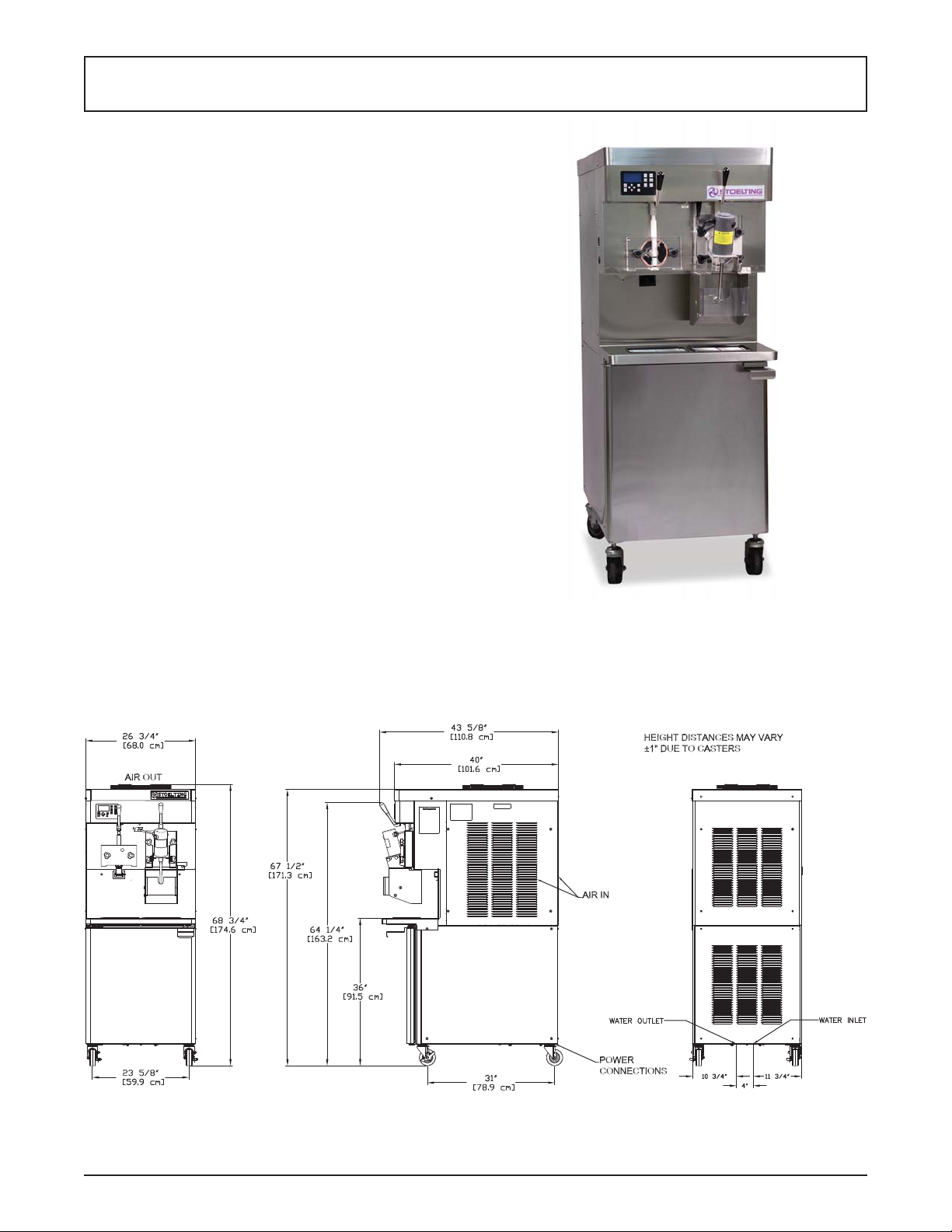
Figure 1-1 Model SU444 I2 Machine
Figure 1-2 Dimensions
Owner’s Manual #513684 1 SU444I2 Model Machines
Page 8

1.2 SPECIFICATIONS
SU444 I2 Water Cooled SU444 I2 Air Cooled
Dimensions Machine with crate Machine with crate
width 26-3/4’’ (67,9 cm) 34’’ (86,4 cm) 26-3/4’’ (67,9 cm) 34’’ (86,4 cm)
height 67-1/2’’ (171,5 cm) 78’’ (198,1 cm) 67-1/2’’ (171,5 cm) 78’’ (198,1 cm)
depth 40’’ (101,6 cm) 48’’ (121,9 cm) 40’’ (101,6 cm) 48’’ (121,9 cm)
Weight 760 lbs (344,7 kg) 908 lbs (411,8 kg) 760 lbs (344,7 kg) 908 lbs (411,8 kg)
Electrical 1 PH 3 PH 1 PH 3 PH
left right left right left right left right
minimum circuit
ampacity
maximum overcurrent
protection device
Compressor
Drive Motor Soft Serve - 2 hp, Shake - 3/4 hp
35A 27A 23A 19A 35A 27A 24A 20A
50A 40A 31A 26A 51A 41A 32A 27A
Soft Serve - 19,000 Btu/hr Scroll™ Compressor (R-404A)
Shake - 15,000 Btu/hr Scroll™ Compressor (R-404A)
Cabinet - 1,300 Btu/hr Compressor (R-134a)
Water cooled units require 1/2” N.P.T.
water and drain fi ttings. Maximum
Cooling
water pressure of 130 psi. Minimum
water fl ow rate of 3 GPM. Ideal EWT
of 50°-70°F. The machine requires 6”
Air cooled units require 6” (15,2 cm) air
space on both sides and back.
(15,2 cm) air space on all sides for the
cabinet refrigeration system.
Hopper Volume Two - 8 gallon (30,28 liters)
Freezing Cylinder
Volume
Soft Serve - 1.33 gallon (5,4 liters)
Shake - 2.1 gallon (7,95 liters)
Owner’s Manual #513684 2 SU444I2 Model Machines
Page 9
SECTION 2
INSTALLATION INSTRUCTIONS
2.1 SAFETY PRECAUTIONS
Do not attempt to operate the machine until the safety
precautions and operating instructions in this manual are
read completely and are thoroughly understood.
Take notice of all warning labels on the machine. The labels have been put there to help maintain a safe working
environment. The labels have been designed to withstand
washing and cleaning. All labels must remain legible for
the life of the machine. Labels should be checked periodically to be sure they can be recognized as warning labels.
If danger, warning or caution labels are needed, indicate
the part number, type of label, location of label, and quantity
required along with your address and mail to:
STOELTING
ATTENTION: Customer Service
502 Hwy. 67
Kiel, Wisconsin 53042
2.2 SHIPMENT AND TRANSIT
The machine has been assembled, operated and inspected
at the factory. Upon arrival at the fi nal destination, the
entire machine must be checked for any damage which
may have occurred during transit.
With the method of packaging used, the machine should
arrive in excellent condition. THE CARRIER IS RESPONSIBLE FOR ALL DAMAGE IN TRANSIT, WHETHER
VISIBLE OR CONCEALED. Do not pay the freight bill
until the machine has been checked for damage. Have
the carrier note any visible damage on the freight bill. If
concealed damage and/or shortage is found later, advise
the carrier within 10 days and request inspection. The
customer must place a claim for damages and/or shortages in shipment with the carrier. Stoelting, Inc. cannot
make any claims against the carrier.
2.3 MACHINE INSTALLATION
WARNING
Installation must be completed by a qualifi ed
electrician/refrigeration specialist.
Incorrect installation may cause personal injury,
severe damage to the machine and will void factory warranty.
Installation of the machine involves moving the machine
close to its permanent location, removing all crating, setting in place, assembling parts, and cleaning.
PRIOR TO INSTALLATION
A. Locate a copy of the service contact fi le (info.txt).
B. Modify the info.txt fi le with information from the
service company using the instructions in the fi le.
C. Put the service contact fi le onto the root level of
a USB fl ash drive (do not put the fi les into any
folder).
INSTALLATION
A. Uncrate the machine.
B. Install the four casters. Turn the threaded end
into the machine until no threads are showing. T o
level, turn out casters no more than 1/4” maximum,
then tighten all jam nuts.
C. The machine must be placed in a solid level
position.
NOTE
Accurate leveling is necessary for correct drainage
of freezing cylinder and to insure correct overrun.
D. Machines with air cooled condensers require a
minimum of 6” (15,2cm) space on all sides and
back for proper circulation.
NOTE
In order for the condenser fan motor to work the
left side needs to be connected to a power source.
E. In air-cooled machines, use a voltmeter to measure
incoming voltage. If the supply voltage is 215 or
less, remove the right side panel and move the
voltage selector toggle switch to the 208V position.
NOTE
Supply voltage must be checked to make sure the
fan motor operates properly.
F. Machines that have a water cooled condenser
require 1/2” NPT supply and drain fi ttings.
2.4 INSTALLING WIRING
A. Refer to the nameplate on the side panel of the
machine for specifi c electrical requirements. Make
sure the power source in the building matches
the nameplate requirements. Bring the wires into
the junction boxes through the access holes in
the bottom rear of the freezer.
NOTE
Three phase freezers in areas of unbalanced electrical loads require special attention when connecting input electrical power. The unbalanced leg of
power (called wild or high) must be connected to
L2 in the junction box.
Owner’s Manual #513684 3 SU444I2 Model Machines
Page 10
6” (15cm)
Figure 2-2 Mix Hose Installation
B. Remove the back panel and the junction box
cover located at the bottom of the machine.
C. Install permanent wiring according to local code.
D. Check the auger shaft rotation by pressing the
Main Power On/Off button and pressing the On/Off
Left or On/Off Right button. The Motor Calibration
screen will be displayed.
E. Move the cursor over the Left side and press the
SEL button then move the cursor over the Right
side and press the SEL button.
F . Auger shaft rotation is clockwise as viewed through
the clear front door.
G. Press the left arrow button to stop the augers
after checking the rotation.
NOTE
Press the left arrow button to exit the calibration
before the 5 minute timer expires. Motor calibration
will be completed in Section 2.6 and must be done
with sanitizer in the freezing cylinders.
2.5 CHECK BLENDER ROTATION
After connecting the electrical, check the blender on the
right side for proper rotation.
A. Place the Blender Power Off/On switch to the ON
position.
B. With the clear swing sheild in place, move the
spigot handle to the right.
WARNING
Hazardous Moving Parts
Blender shaft and agitator can grab and cause
injury. Do not operate blender without protective
shield or swing splash shield.
C. The blender should rotate clockwise looking from
the top of the blender.
D. If the rotation is counterclockwise, refer to the
wiring diagram located behind the header panel
and check the diode direction. Reverse the diode
polarity if needed.
2.6 MIX PUMP
A. MIX PUMP HOSE INSTALLATION
Follow the steps below to install the mix pump hose in
the cabinet part of the machine.
1. Turn the mix pump on by pressing the Pump On/
Off button on the touchpad.
2. Feed one end of the mix pump hose into the
entering or pickup hose side (left) of black cover
(Fig 2-2).
NOTE
Feed the tube into the clamp so the natural curve of
the tube is towards the outside of the black cover.
This prevents the hose from looping around the
black cover twice.
3. Gently push the hose into the black cover until it
begins to feed.
Owner’s Manual #513684 4 SU444I2 Model Machines
Page 11
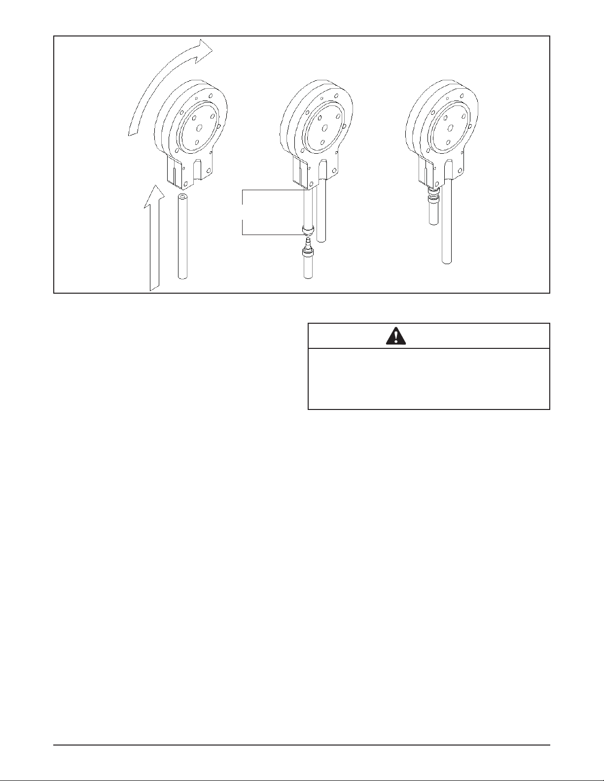
Figure 2-3 Mix Pump Connections for Standard Mix Container
4. Allow the hose to feed itself through the pump
until about 6” (15cm) remains on the entering
side.
5. Turn the pump off.
6. Connect the mix pump hose to the elbow fi tting
(located on the left side of the mix line manifold)
using a small hose clamp. Be careful not to twist
the mix hose.
7. Turn the pump on.
8. Allow the remaining 6” (15cm) of tubing to feed
through pump until the hose adapter prevents
further feeding.
9. Turn the pump off.
CAUTION
Risk of Product Damage
Air/Mix Tee must remain below the black cover
clamp. If the T ee is above the pump, mix may drain
into the air compressor resulting in pump damage.
10. Connect the free end of the mix pump hose to
the 3-way Tee (Fig. 2-3). When all connections
are complete, the 3-way Tee must be lower than
the black pump housing.
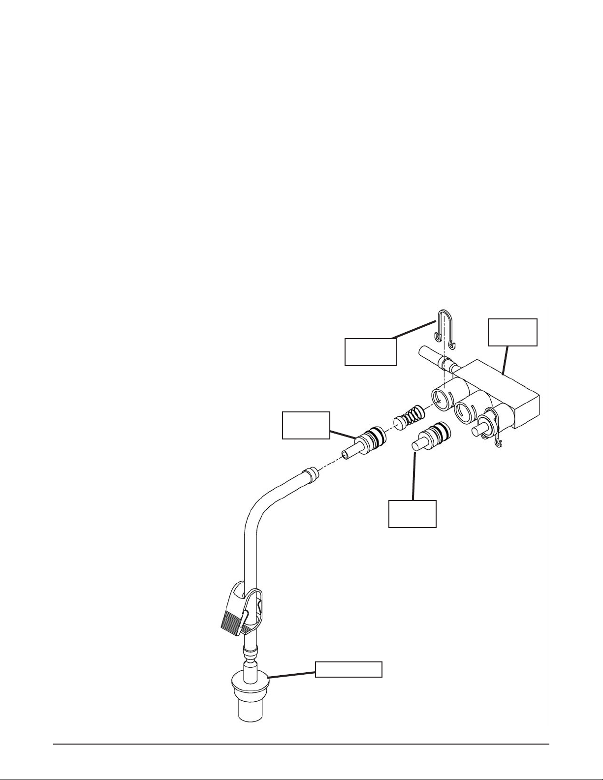
B. MIX PICKUP HOSE INSTALLATION
The machine may be connected to the standard mix
container or up to three prepacked mix bags. Follow the
instructions below that match your confi guration.
Standard Connection:
1. Place the mix pickup assembly through the hole
in the cover and install the retaining clip.
2. Connect a 24” (61cm) length of 3/8” (9,5mm)
ID plastic food grade tubing to the mix pickup
assembly and secure with a hose clamp.
3. Connect the elbow fi tting to the free end of the
tubing. Connect the opposite end of the elbow
to 1/4” ID tan tubing on the left side of the pump
head. Secure with hose clamps (Fig. 2-3).
When Using Bag Connection System (BCS) with Three
Bags (optional kit #2183987):
The position of the three bags in the mix container is
important. The bag that is connected nearest the outlet
of the manifold will drain last and should be placed at
the back of the mix container. The mix low level indicator
relies on proper bag placement.
1. Connect 3/8” (9,5mm) ID plastic food grade tubing
to a bag adapter. Secure with hose clamps.
Owner’s Manual #513684 5 SU444I2 Model Machines
Page 12
2. Slide the hose clip over free end of 3/8” (9,5mm)
ID plastic food grade tubing. Attach the free end
of the tubing to a manifold adapter. Secure with
a large hose clamp or equivalent.
3. Push the manifold adapter with spring and valve
into the left port (nearest the manifold outlet) of
the mix inlet manifold and secure with a retaining
clip. (Fig. 2-5).
4. Repeat steps 1 to 3 for the middle port and for
the right port of the mix inlet manifold.
5. Place three mix bags into the mix container.
6. Connect the bag adapter attached to the left side
of the manifold (closest to the mix outlet) to the
mix bag in the back of the mix container.
7. Connect the bag adapter attached to the middle
of the manifold to the mix bag in the middle of
the mix container.
8. Connect the bag adapter attached to the right
side of the manifold (farthest from the mix outlet)
to the mix bag in the front of the mix container.
When Using Bag Connection
System (BCS) with One or T wo
Bags (optional kit #2183987):
When connecting one or two
bags, the manifold adapters
must be installed closest to the
manifold outlet and the manifold
plug(s) must be placed farthest
from the manifold outlet.
1. Connect 3/8” (9,5mm) ID
plastic food grade tubing
to a bag adapter. Secure
with hose clamps.
2. Slide the hose clip
over the free end of
the tubing. Attach the
free end of the tubing
to a manifold adapter.
Secure with a large hose
clamp.
3. Push the manifold
adapter with spring and
valve into the left port
(nearest the manifold
outlet) of the mix inlet
manifold and secure
with retaining clip. (See
Figure 2-5).
4. If using two mix bags,
repeat steps 1 to 3 for
the middle port.
5. Install a manifold plug
into each empty inlet and
secure with a retaining
clip.
Owner’s Manual #513684 6 SU444I2 Model Machines
Figure 2-4 Bag Connection System (Optional)
6. Place the mix bag(s) into the mix container.
7. Connect the bag adapter attached to the left side
of the manifold (closest to the mix outlet) to the
mix bag in the back of the mix container.
2.7 INTELLITEC2™ SETUP
A. Disassemble, clean, lubricate and assemble the
machine following the steps in Section 3.
B. Fill the mix containers in the cabinet with sanitizer.
C. Connect power to the machine and press the
Main Power On/Off button.
NOTE
The Current Status screen should show “Calibration Required” for both cylinders. If it does not, go
to the Unit Calibration option in the Utilities menu
to complete the calibration.
D. Press the Pump On/Off button when the Current
Status screen is displayed.
Mix Inlet
Retaining
Clip
Manifold
Adapter
Manifold
Plug
Bag Adapter
Manifold
Page 13
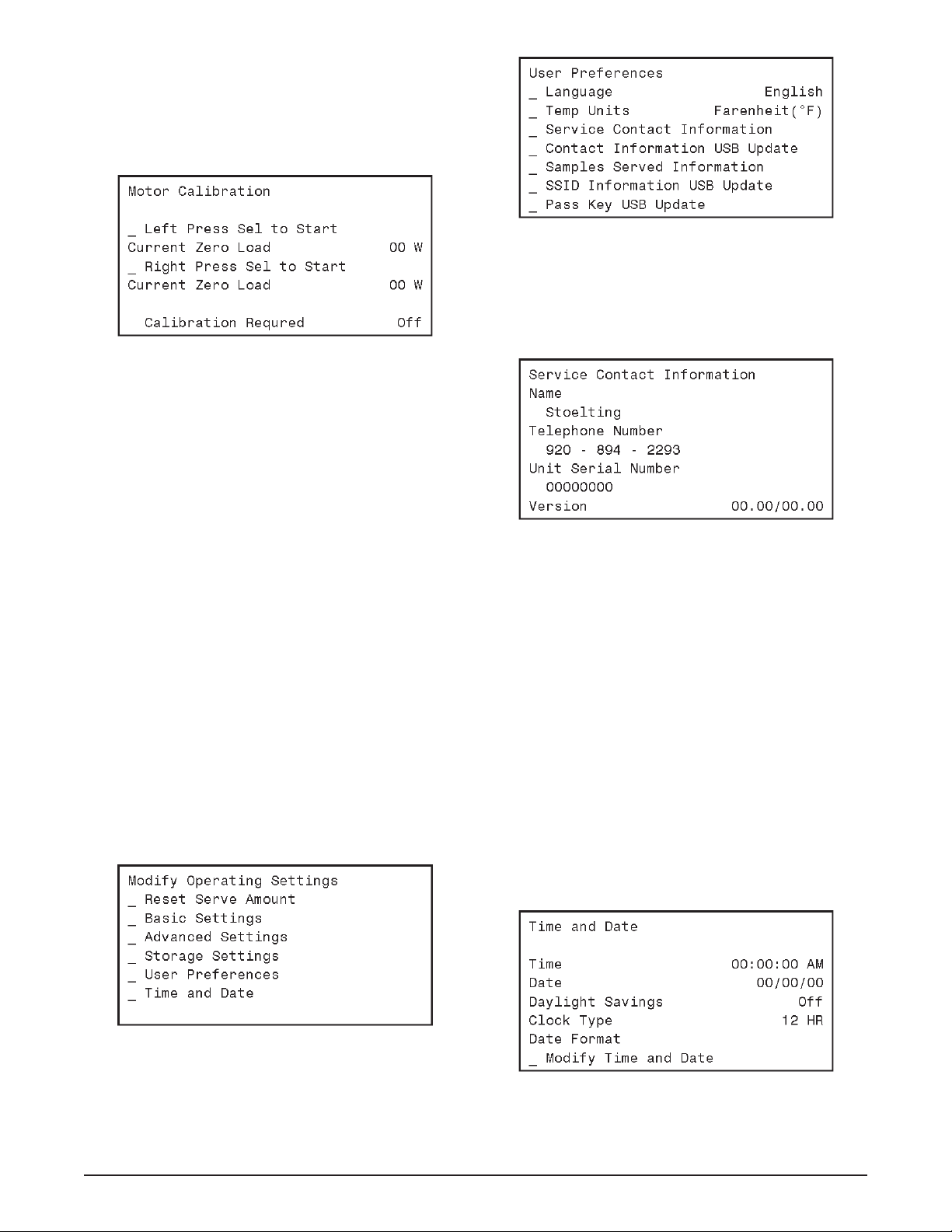
MOTOR CALIBRATION
Before starting the motor calibration, be sure there is
sanitizer in the freezing cylinder.
A. Press the On/Off Left or On/Off Right button. The
Motor Calibration screen will be displayed.
Figure 2-5
B. Move the cursor over the Left side and press the
SEL button then move the cursor over the Right
side and press the SEL button.
NOTE
The motor calibration can be done for both sides
simultaneously.
C. After the calibration is complete, press the left
arrow button.
D. Drain the machine of sanitizer.
E. Press the Pump On/Off button.
SETTING CONTACT INFORMATION
A. Plug your USB fl ash drive into the control if it is
not already plugged in.
B. From the Current Status screen, press the left
arrow button to access the passcode selection
screen. Press the right arrow, SET, and then the
SEL button.
C. After the password is accepted, use the arrows to
move the cursor to the Modify Settings option and
press the SEL button. Then move the cursor to
the User Preferences and press the SEL button.
Figure 2-7
E. The screen will change and show “File Found” for
a quick second while it updates the information.
F . After updating the contact information, the screen
will show the Service Contact Information page.
Figure 2-8
G. Press the left arrow button to go back to the Current
Status screen and remove the USB fl ash drive.
SETTING TIME AND DATE
A. Press the right arrow button.
B. Move the cursor to the Modify Settings option
and press the SEL button. Then move the cursor
to the Time and Date option and press the SEL
button and adjust the settings as required.
1. Press the SEL button to enter the Modify
Time and Date screen.
2. Move the cursor to the setting that needs
to be changed and press the SET button.
3. Use the arrow buttons to change the
setting and press the SET button to save the
change.
Figure 2-6
D. On the User Preferences screen move the cursor
to the Contact Information USB Update and press
the SEL button.
Owner’s Manual #513684 7 SU444I2 Model Machines
C. Press the left arrow button until the Current Status
screen is displayed.
Figure 2-9
Page 14

SETTING CONSISTENCY
A. Fill the mix container with liquid mix.
B. Press the Pump On/Off button. Prime the freezing
cylinder. After the pump button is pressed, mix will
partially fi ll the freezing cylinder and the pump will
cycle off. After the pump turns off, press the air
bleed valve on the front door to prime the freezing
cylinder. Release the valve and pull outwards.
Make sure the mix level in the freezing cylinder
is above the hub on the auger shaft.
C. Press the Push to Freeze button and let the
machine cycle 4-5 times.
D. Draw product from the barrel immediately after
the compressor cycles off after the fi fth time and
test the product for consistency and temperature.
E. Adjust the product consistency by increasing or
decreasing the Consist Offset settings. These
settings are under the Modify Settings Basic
Settings menu
F. If the machine short cycles (short on/off
compressor run times), change the settings as
follows:
1. If the product is too soft, increase the
CutIn Consist Offset.
2. If the product is too fi rm, decrease the
CutIn Consist Offset.
F. After the consistency is set, press the left arrow
button once so that the Modify Operating Settings
screen is displayed.
SETTING SERVE TIME AND OVERRUN DETAILS
A. Go to the Advanced Settings (2 of 3) screen and
scroll down to the Time to Dispense 16 oz option.
B. Time how long it takes to dispense 16 oz of product
into a cup and change the value in the control.
C. Measure to overrun of the product and change
the value in the control. To measure overrun, do
the following:
1. Zero a scale with an 8 - 16 oz cup.
2. Fill the cup with liquid mix and weigh it.
Make sure the mix is fi lled to the rim.
3. Fill the cup with frozen product.
4. Scrape the top of the cup with a straight
edge.
5. Weigh the fi lled cup.
6. Calculate the overrun using the following
equation:
SETTING DISCHARGE PRESSURE ON WATER
COOLED MACHINES
A. Water cooled machines require the water
condenser valves to be adjusted to maintain a
235-240 psig discharge pressure.
When adjusting the discharge pressure the
machine must be under a full load with both
cylinders running.
D. Change the value in the control.
E. Press the left arrow button until the Current Status
screen is displayed.
Owner’s Manual #513684 8 SU444I2 Model Machines
Page 15

SECTION 3
INITIAL SET-UP AND OPERATION
3.1 OPERATOR’S SAFETY PRECAUTIONS
SAFE OPERATION IS NO ACCIDENT; observe these
rules:
A. Know the machine. Read and understand the
Operating Instructions.
B. Notice all warning labels on the machine.
C. Wear proper clothing. Avoid loose fi tting garments,
and remove watches, rings or jewelry that could
cause a serious accident.
D. Maintain a clean work area. Avoid accidents by
cleaning up the area and keeping it clean.
E. Stay alert at all times. Know which switch, push
button or control you are about to use and what
effect it is going to have.
F. Disconnect power for maintenance. Never
attempt to repair or perform maintenance on the
machine until the main electrical power has been
disconnected.
G. Do not operate under unsafe operating conditions.
Never operate the machine if unusual or excessive
noise or vibration occurs.
3.2 OPERATING CONTROLS AND INDICATORS
Before operating the machine, it is required that the operator know the function of each operating control. Refer
to Figure 3-1 for the location of the operating controls on
the machine. For the information regarding error codes
displayed on the control panel, refer to the troubleshooting
section of this manual.
WARNING
High voltage will shock, burn or cause death. Make
sure the display shows the freezing cylinders and
pump are off. If they are not, press the On/Off button
and Pump button to turn them off prior to disassembling for cleaning or servicing. Do not operate
machine with panels removed.
IntelliT ec2™ Control
(See Figure 3-2)
Blender Power
Off/On Circuit
Breaker
Figure 3-1 SU444 Freezer Controls
Owner’s Manual #513684 9 SU444I2 Model Machines
Page 16

A. INTELLITEC2™ TOUCHPAD
Main Power On/Off
The Main Power button is used to supply power to the
IntelliTec2™ control, the freezing cylinder circuits and
the storage refrigeration system. When the machine is
fi rst plugged in, the control defaults to the On status with
power to the hopper only . If the Main Power On/Off button
is pressed when the machine is on, the machine will turn
off and a status message will be displayed on the screen.
Help
Pressing the Help button will display help information
dependant on the cursor’s location. Pressing the Help
button again will exit the help screen.
Selection Button (SEL)
The SEL button is used by technicians to select menu
options.
Set Button (SET)
The SET button is used by technicians to save changes
when modifying control settings.
On/Off Button
Power to the freezing cylinders can then be controlled
with the On/Off Left and On/Off Right switches.
Push to Freeze Button
Pressing the PUSH TO FREEZE button initiates “Serve
Mode”.
Clean Button
The CLEAN button initiates “Clean Mode”.
Arrow Buttons ()
The arrow buttons are used by technicians to navigate
through the control readings and settings.
B. SPIGOT SWITCH
The spigot switch is mounted to the spigot cam assembly
behind the header panel. When the spigot is opened to
dispense product, the spigot switch opens and the “Serve
Mode” begins.
C. DISPENSE RATE ADJUSTOR (LEFT SIDE)
The dispense rate adjustor is located under the header
panel, to the immediate right of the spigot handles. Turning
the knob counterclockwise will decrease the dispense rate.
D. BLENDER POWER ON/OFF CIRCUIT BREAKER
(RIGHT SIDE)
The Blender Power Off/On and Circuit Breaker switch is
a two position toggle switch used to supply power to the
blender. When the switch is in the OFF position, there is
no power to the blender. When the switch is in the ON
position, the blender will operate any time the spigot
handle is pushed to the right. This switch also serves as
a circuit breaker to interrupt power if the rotation of the
blender agitator becomes hindered..
Figure 3-2 IntelliTec2™ Control
E. USB ACCESS PORT
The USB access port is located on the right side panel
of the machine. The port is used by technicians to import
fi rmware and export machine statistics.
3.3 DISASSEMBLY OF LEFT SIDE
WARNING
Moving machinery can grab, mangle and dismember. Make sure the display shows that the machine
is off. If it is not, press and hold the Main Power
button until the display shows that it is off.
Before using the machine for the fi rst time, complete
machine disassembly, cleaning and sanitizing procedures need to be followed. Routine cleaning intervals
and procedures must comply with the local and state
health codes. Inspection for worn or broken parts should
be made at every disassembly of the machine. All worn
or broken parts should be replaced to ensure safety to
both the operator and the customer and to maintain good
machine performance and a quality product.
To disassemble the left side, refer to the following steps:
A. REMOVE FRONT DOOR AND AUGER
1. Remove the knobs on the front door and remove
the door by pulling it off the studs.
2. Remove the air bleed valve by unscrewing the
knob while holding the valve stem from behind.
Remove the compression spring and push the
air bleed valve through the rear of the front door.
3. Remove the spigot through the bottom of the front
door. Remove all o-rings from the spigot and the
air bleed valve.
4. Remove the front auger support and plastic
bearing.
5. Remove the auger by pulling slowly and rotating
out of the machine barrel. As the auger is
withdrawn, remove each plastic fl ight and spring
from the auger. Be careful not to scratch inside of
machine barrel when removing fl ights or auger.
Remove the spring from each auger fl ight.
Owner’s Manual #513684 10 SU444I2 Model Machines
Page 17

Remove O-Ring
From Inside Insert
Collar
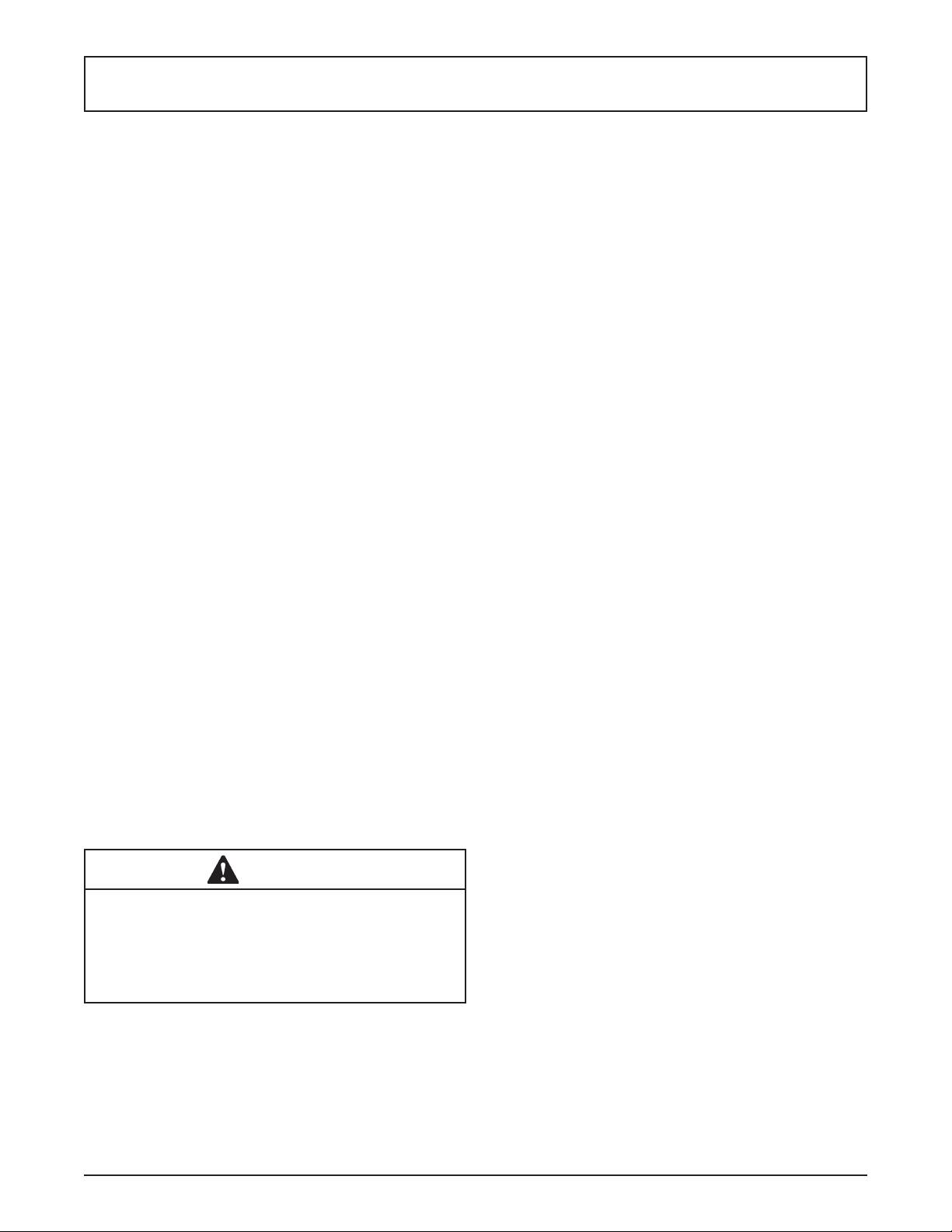
Figure 3-3 Rear Seal Assembly
7. Keep the rear of the auger tipped up once it is
clear of the freezing cylinder to prevent the rear
seal assembly from dropping.
8. Wipe the spline lubricant off the hex end of the
auger with a paper towel. Remove the rear seal
assembly (Fig. 3-3).
NOTE
Keep the rear seal assembly separate from the
right side assembly to prevent problems when assembling.
3.4 DISASSEMBLY OF RIGHT SIDE
WARNING
Moving machinery can grab, mangle and dismember. Make sure the display shows that the machine
is off. If it is not, press and hold the Main Power
button until the display shows that it is off.
Before using the machine for the fi rst time, complete
machine disassembly, cleaning and sanitizing procedures need to be followed. Routine cleaning intervals
and procedures must comply with the local and state
health codes. Inspection for worn or broken parts should
be made at every disassembly of the machine. All worn
or broken parts should be replaced to ensure safety to
both the operator and the customer and to maintain good
machine performance and a quality product.
T o disassemble the machine, refer to the following steps:
A. REMOVE BLENDER (SU444 ONLY)
1. Make sure the Main Power is OFF. If it is not,
press and hold the Main Power button until the
display shows that it is off.
2. Unplug the blender.
3. Remove the blender agitator by holding the blender
shaft and turning the agitator counterclockwise.
Remove the blender shaft by holding the blender
collar and turning the shaft counterclockwise
(Fig. 3-4).
Shaft
Figure 3-4 SU444 Blender Agitator Assembly
4. Loosen knobs holding the blender splash shield
bracket in place and remove the bracket.
5. Remove the knobs on the front door. Remove
the blender assembly and set aside.
NOTE
Support the blender with one hand while removing
the knobs on the door to prevent the blender from
dropping.
B. REMOVE FRONT DOOR AND AUGER
1. Make sure the Main Power is OFF. If it is not,
press and hold the Main Power button until the
display shows that it is off.
2. Remove the knobs on the front door and remove
the door by pulling it off the studs.
3. Remove the air bleed valve by unscrewing the
knob while holding the valve stem from behind.
Remove the compression spring and push the
air bleed valve through the rear of the front door.
4. Remove the spigot through the bottom of the front
door. Remove all o-rings from the spigot and the
air bleed valve.
5. Remove the plastic bearing. The plastic bearing
may be on the front door.
6. Remove the auger by pulling slowly. Be careful
not to scratch the inside of the freezing cylinder
when removing the auger.
7. Keep the rear of the auger tipped up once it is
clear of the freezing cylinder to prevent the rear
seal assembly from dropping.
Agitator
Owner’s Manual #513684 11 SU444I2 Model Machines
Page 18

8. Wipe the spline lubricant off the hex end of the
auger with a paper towel. Remove the rear seal
assembly.
NOTE
Keep the rear seal assembly separate from the
right side assembly to prevent problems when assembling.
3.5 CLEANING DISASSEMBLED PARTS
Disassembled parts require complete cleaning, sanitizing and air drying before assembling. Local and state
health codes will dictate the procedure required. Some
state health codes require a four sink process (pre-wash,
wash, rinse, sanitize, air dry), while others require a three
sink process (without the pre-wash step). The following
procedures are a general guideline only. Consult your
local and state health codes for the procedures required
in your location.
A. Disassemble all parts.
B. Place all front door and auger parts in clean 90° to
1 10°F (32°C to 43°C) water and wash thoroughly
(four sink procedure only).
CAUTION
The blender motor cannot be immersed in water
or sanitizer. W ash the motor and mounting bracket
with a mild detergent solution taking care not to allow water into the motor bearings or seals.
C. Place all parts in 90° to 110°F (32°C to 43°C) mild
detergent water and wash thoroughly.
D. Rinse all parts with clean 90° to 110°F (32°C to
43°C) water.
E. Sanitize all machine parts following procedures
outlined below.
3.6 SANITIZING PARTS
A. Use a sanitizer, mixed according to manufacturer’s
instructions, to provide a 100 parts per million
strength solution. Mix sanitizer in quantities of
no less than 2 gallons of 90° to 110°F (32°C to
43°C) water. Any sanitizer must be used only in
accordance with the manufacturer’s instructions.
B. Place all parts in the sanitizing solution for 5
minutes, then remove and let air dry completely
before assembling in machine.
Do not use highly abrasive materials, as they will mar the
fi nish. A mild alkaline cleaner is recommended. Use a soft
cloth or sponge to apply the cleaner. For best results, wipe
with the grain of the steel.
A. Clean the rear seal surfaces on the inside of the
freezing cylinders.
B. Using sanitizing solution and the large barrel
brush provided, sanitize the freezing cylinders by
dipping the brush in the sanitizing solution and
brushing the inside of the freezing cylinders.
C. Remove the drip trays from the front panel. Clean
and replace the drip trays.
3.8 ASSEMBLING THE LEFT SIDE
Refer to the following steps for assembling the left freezing cylinder:
NOTICE
Petrol-Gel sanitary lubricant or equivalent must be
used when lubrication of machine parts is specifi ed.
NOTICE
The United States Department of Agriculture and
the Food and Drug Administration require that lubricants used on food processing equipment be certifi ed for this use. Use lubricants only in accordance
with the manufacturer’s instructions.
A. Assemble all o-rings onto parts dry, without
lubrication. Then apply a thin fi lm of sanitary
lubricant to exposed surfaces of the o-rings.
B. Install the rear seal o-ring. Lubricate the outside
of the rear seal o-ring with sanitary lubricant.
C. Install the stainless steel rear seal adapter into
the rear seal dry (without lubricant). Lubricate the
inside surface of the rear seal adapter, including
the adapter o-ring, and install it onto the auger
shaft. DO NOT lubricate the outside of the rear
auger seal (Fig. 3-4).
Petrol-Gel
Place O-Ring
Inside Insert
3.7 CLEANING THE MACHINE
The exterior should be kept clean at all times to preserve
the luster of the stainless steel. A high grade of stainless
steel has been used on the machine to ease cleanup. To
remove spilled or dried mix, wash the exterior with 90° to
110°F (32°C to 43°C) soapy water and wipe dry.
Owner’s Manual #513684 12 SU444I2 Model Machines
Spline
Lubricant
Figure 3-4 Rear Seal Assembly
Page 19

Figure 3-5 Left Auger and Door
NOTE
Make sure to install the correct rear seal adapter
onto the auger. The front door will not close if the
right side rear seal adapter is installed onto the left
side auger.
D. Lubricate the hex drive end of the auger with a
small amount of spline lubricant. A small container
of spline lubricant is shipped with the machine.
E. Screw the springs onto the studs in the plastic
fl ights. The springs must be screwed into the
fl ights completely to provide proper compression.
F. Install the two plastic fl ights onto the rear of the
auger and insert it part way into the freezing
cylinder.
G. Install the remaining plastic fl ights, push the auger
into the freezing cylinder and rotate slowly until
the auger engages the drive shaft.
H. Apply a thin layer of Petrol-Gel to the inside and
outside of the auger support bushing. Install the
bushing onto the auger support and install the
auger support into the front of the auger. Rotate
the auger support so that one leg of the support
points straight up.
I. Assemble the air bleed valve o-ring onto the air
bleed valve. Position the o-ring into the groove
close to the wide part. Apply a thin fi lm of sanitary
lubricant to the o-ring.
J. Insert the air bleed valve into the back of the front
door. Install the compression spring onto the air
bleed valve then screw the knob on fi nger tight.
K. Apply a thin layer of sanitary lubricant to the
o-rings on the spigot body and install the spigot
body through the bottom of the front door.
L. Place the front door assembly on the mounting
studs and the push front door against the machine
carefully.
M. Secure the front door to the machine by placing
the knobs on the studs and tightening until fi nger
tight. Do not overtighten. Proper o-ring seal can
be observed through the transparent front door.
3.9 ASSEMBLING THE RIGHT SIDE
Refer to the following steps for assembling the right
freezing cylinder:
NOTICE
Petrol-Gel sanitary lubricant or equivalent must be
used when lubrication of machine parts is specifi ed.
NOTICE
The United States Department of Agriculture and
the Food and Drug Administration require that lubricants used on food processing equipment be certifi ed for this use. Use lubricants only in accordance
with the manufacturer’s instructions.
A. Assemble all o-rings onto parts dry, without
lubrication. Then apply a thin fi lm of sanitary
lubricant to exposed surfaces of the o-rings.
B. Install the rear seal o-ring. Lubricate the outside
of the rear seal o-ring with sanitary lubricant.
C. Install the stainless steel rear seal adapter into
the rear seal dry (without lubricant). Lubricate the
inside surface of the rear seal adapter, including
the adapter o-ring, and install it onto the auger
shaft. DO NOT lubricate the outside of the rear
auger seal.
NOTE
Make sure to install the correct rear seal adapter
onto the auger. The back of the cylinder will leak if
the left side rear seal adapter is installed onto the
right side auger.
Figure 3-6 Right Auger and Door
Owner’s Manual #513684 13 SU444I2 Model Machines
Page 20

D. Lubricate the hex drive end of the auger with a
small amount of spline lubricant. A small container
of spline lubricant is shipped with the machine.
E. Install the plastic scraper blades onto the auger
and insert the auger into the freezing cylinder.
F. Rotate the auger until it engages the drive shaft.
G. Assemble the air bleed valve o-ring onto the air
bleed valve. Position the o-ring into the groove
close to the wide part. Apply a thin fi lm of sanitary
lubricant to the o-ring.
H. Insert the air bleed valve into the back of the front
door. Install the compression spring onto the air
bleed valve then screw the knob on fi nger tight.
I. Install the spigot through the bottom of the front
door.
J. Apply a thin fi lm of sanitary lubricant to the inside
and outside of the plastic bearing, then place it
into the front door.
K. Place the front door assembly on the mounting
studs and the push front door against the machine
carefully.
L. On the SU444, place the blender assembly onto
the front door studs.
M. Secure the front door to the machine by placing
the knobs on the studs and alternately tightening
opposite corners until finger tight. Do not
overtighten. Proper o-ring seal can be observed
through the transparent front door.
N. On the SU444, attach the blender shroud to the
blender assembly . The blender shroud has a pin
that needs to be properly aligned with the machine
safety switch.
3.10 SANITIZING
Sanitizing must be done after the machine is clean and
just before the machine is fi lled with mix. Sanitizing the
night before is not effective. However , you should always
clean the machine and parts after using it.
NOTE
The United States Department of Agriculture and
the Food and Drug Administration require that all
cleaning and sanitizing solutions used with food
processing equipment be certifi ed for this use.
When sanitizing the machine, refer to local sanitary regulations for applicable codes and recommended sanitizing
products and procedures. The frequency of sanitizing
must comply with local health regulations. Mix sanitizer
according to manufacturer’s instructions to provide a 100
parts per million strength solution. Mix sanitizer in quantities of no less than 2 gallons of 90°F to 110°F (32°C to
43°C) water. Allow sanitizer to contact the surfaces to be
sanitized for 5 minutes. Any sanitizer must be used only
in accordance with the manufacturer’s instructions.
CAUTION
Risk of Product Damage
Avoid prolonged contact of sanitizer with machine
parts. Sanitizer may cause corrosion of stainless
steel parts if there is prolonged contact.
A. Prepare 3 gallons of sanitizing solution following
manufacturer’s instructions for each side, and
pour it into the storage containers.
B. Make sure the display shows the freezing cylinders
are off. If they are not, Press the On/Off Left or
On/Off right button to turn it off.
NOTE
If the freezing cylinder is not off, the control will
not go into Clean mode. This is to protect from accidentally going into Clean mode.
C. Press the Pump button to turn the pump ON
and open the air bleed valve on the front door by
pushing the valve in and holding.
D. Let sanitizing solution fi ll the machine barrel to
air bleed valve, then close the valve by pulling
out to lock in place.
E. Press the CLEAN button to start the auger rotating.
F. Check for leaks when the machine barrel is fi rst
pressurized with sanitizing solution.
1. Check for leaks at the front door.
2. Check the drain located at the center of the
Drip Tray for leaks coming from the rear of the
Rear Auger Seal.
3. Check inside cab unit for leaks at hose
connections.
G. Using a sanitized soft bristle brush or equivalent,
dipped in sanitizing solution, clean mix container.
H. Empty any remaining sanitizing solution from the
mix container.
I. After fi ve minutes, open spigot to drain sanitizing
solution.
J. Sanitize the agitator and shaft with a cup fi lled
with sanitizing solution.
K. When the solution has drained, press the Pump
and Clean buttons to stop the pump and auger.
Allow the freezing cylinder to drain completely.
The machine is now sanitized and ready for adding mix.
Owner’s Manual #513684 14 SU444I2 Model Machines
Page 21

3.11 NORMAL FREEZE DOWN AND
OPERATION
Refer to the following procedures to operate both freezing cylinders.
A. Sanitize immediately before use.
B. Make sure the display shows the freezing cylinders
are off. If they are not, Press the On/Off Left or
On/Off right button to turn it off.
C. Fill the storage container in the cab with at least
2.5 gallons of mix.
D. Attach the mix inlet probe to the container and
place the container in the refrigerated cab.
E. Press the Pump button to turn the pump on.
F . Place a container under the spigot and open it to
allow the mix to fl ush out about 8 ounces (0.23
liters) of sanitizing solution and liquid mix. Close
the spigot.
G. Open the air bleed valve on the front door by
pressing and holding. Hold the valve open until
the mix level in the freezing cylinder is 1/2” from
the air bleed valve.
H. Press the On/Off button for the cylinder.
I. Press the PUSH TO FREEZE button.
I. On the SU444 right side, make sure the blender
power plug is connected to the machine and
place the Blender Power Off/On switch in the ON
position.
WARNING
Hazardous Moving Parts
Blender shaft and agitator can grab and cause
injury. Do not operate blender without protective
shield or swing splash shield.
J. When the product is ready, the display will read
“SERVE”. Open the spigot to dispense product.
NOTE
If the product consistency needs to be adjusted, use
the Technician passcode and go to the Basic Settings menu. Adjust the CutOut Consistency higher
to increase the consistency or lower to decrease
the consistency. Make adjustments in increments
of 5 for best results.
L. On the SU444 right side, push the spigot handle
to the right to activate the blender. The blender
will operate during or after dispensing product.
M. Do not operate the machine when the MIX LOW
message is displayed. Refi ll the mix containers
immediately.
NOTE
The machine has a standby and sleep mode. After
a preset number of freezing cycles, it will enter the
standby mode (followed by sleep mode) and remain
there until someone draws product or presses the
PUSH TO FREEZE button. In the sleep mode, the
machine will keep the product below 41°F (7.2°C).
Sleep modes do not take the place of cleaning
and sanitizing. Federal, State, and local regulatory
agencies determine frequency of cleaning and
sanitizing.
3.12 MIX INFORMATION
Mix can vary considerably from one manufacturer to
another. Differences in the amount of butterfat content
and quantity and quality of other ingredients have a
direct bearing on the fi nished frozen product. A change
in machine performance that cannot be explained by a
technical problem may be related to the mix.
Proper product serving temperature varies from one
manufacturer’s mix to another. Mixes should provide a
satisfactory product in the 20°F to 24°F range. Diet and
low-carb mixes typically freeze to proper consistency at
higher temperatures.
When checking the temperature, stir the thermometer in
the frozen product to get an accurate reading.
Old mix, or mix that has been stored at too high a temperature, can result in a fi nished product that is unsatisfactory.
To retard bacteria growth in dairy based mixes, the best
storage temperature range is between 33° to 38°F (0.5°
to 3.3° C).
3.13 OPERATION OF MIX PUMP
The mix pumps are operated from the buttons on the
IntelliT ec2™ touchpad. When the pump button is pressed
On, the mix pump motor will start pumping mix into the
freezing cylinder. When the set pressure is reached, the
mix pump will shut off automatically.
NOTE
The mix pump motor is equipped with an internal
overload that will “trip”, disabling the pump when
the motor is overloaded. Consult the troubleshooting section for corrective information. The internal
overload will automatically reset after cooling. If
the condition continues, contact a qualifi ed service
person.
Owner’s Manual #513684 15 SU444I2 Model Machines
Page 22

Air/mix to
Air Line
Mix
Intake
Figure 3-7 Mix Pump Hose Routing
A. Mix Operation: The peristaltic mix pump contains
one continuous mix pump hose. When looking at
the face of the peristaltic mix pump, the left side
of the hose is the mix intake or pickup. The right
side of the hose is the mix discharge. Mix is drawn
up the pickup side of the hose and transferred
through the discharge side to the machine (Fig.
3-7).
B. Air Operation: The air compressor operates
whenever the peristaltic mix pump is running.
Air enters through a check valve on the piston
downstroke. The air is discharged through a
second check valve, on the piston upstroke. The
air and mix join at the tee and then travel to the
machine.
C. The overrun adjustment is preset at the factory.
If an adjustment becomes necessary, refer to
Section 4.
Freeezing
Cylinder
3-way
Tee
Mix
Discharge
3.14 MIX PUMP CLEANING
NOTICE
Any cleaning procedure must always be followed
by sanitizing before fi lling machine with mix.
The mix pump is approved for CIP (clean in place). It is
thoroughly cleaned when the cleaning solution is pumped
through the machine. We recommend completely disassembling the pump and disconnecting tubing every 14
days for inspection of parts to confi rm the CIP has been
properly performed. If any residue is detected, clean or
replace those parts as outlined below.
A. With the machine fi lled with mix, press the Clean
button. Allow the auger to agitate for 5 to 10
minutes.
B. Remove the suction tube from the mix container.
Open the spigot to remove the mix remaining in
the freezing cylinder.
C. Pump 2 gallons (7.5 liters) of potable water through
machine until the water coming out of the spigot
is clear.
D. Pump 2 gallons (7.5 liters) of 90° to 110°F (32°C
to 43°C) cleaning solution through the machine.
E. Press the Pump button to turn the pump Off. Open
the spigot to relieve the remaining pressure.
F . Press the Clean button to stop the cleaning cycle
and press the On/Off button for the cylinder to
turn it Off.
3.15 DISASSEMBLY AND INSPECTION OF
REMOVABLE PARTS
Inspection of removable parts should be made whenever
maintenance is performed or when the pump requires
disassembly.
NOTE
If the mix line or air line is diffi cult to remove, soften
the tubing with a rag soaked in hot water. Hose
connections may be sprayed with Haynes Sanitary
Lubricant for ease of removal.
WARNING
Hazardous Moving Parts
Revolving pump head can grab, mangle, and cause
serious crushing injury. Make sure the display
shows the freezing cylinders and pump are off. If
they are not, press the On/Off button and Pump
button to turn them off.
CAUTION
System Under Pressure
Never disconnect hoses from the machine or the
pump without fi rst opening the spigot to relieve
pressure.
A. Loosen the clamp and remove the air hose from
the pump compressor.
B. Loosen the clamp and disconnect the mix pump
hose. Remove the pickup hose, and the mix
pickup assembly from the mix container.
Owner’s Manual #513684 16 SU444I2 Model Machines
Page 23

Figure 3-8 Mix Pump Removable Parts
C. Completely disassemble the hose assembly and
the check valve (Fig. 3-8). Place hoses, tee, check
valve assembly , and pickup hose adapter in 90°
to 1 10°F (32°C to 43°C) mild detergent water and
wash thoroughly . Use soft bristle brushes to clean
inside of fi ttings. Rinse all parts in clean 90° to
110°F (32°C to 43°C) water.
D. Carefully inspect each part for wear or damage.
Replace worn or damaged parts.
E. Wash the mix tube and the air tube in the cabinet
with 90° to 110°F detergent water and brushes
provided. Rinse with clean, 90° to 110°F water.
F. Prepare two gallons (7.5 liters) of sanitizing
solution using a USDA certifi ed grade sanitizing
solution. Sanitize all removed parts. Allow them
to air dry.
G. Reassemble both hose assemblies per the
diagram located on the inside of the cab door.
Reconnect the assemblies to the pump hose and
the discharge hose, using the clamps. (Refer to
Section 2.6 Mix Pump).
H. Sanitize assembled machine as per instructions
outlined in Section 3.10.
Owner’s Manual #513684 17 SU444I2 Model Machines
Page 24

Owner’s Manual #513684 18 SU444I2 Model Machines
Page 25

SECTION 4
MAINTENANCE AND ADJUSTMENTS
This section is intended to provide maintenance personnel
with a general understanding of the machine adjustments.
It is recommended that any adjustments in this section
be made by a qualifi ed person.
4.1 OVERRUN ADJUSTMENT
The product, when served, is a combination of air and
mix. Overrun is a measure of the amount of air blended
into the mix.
Overrun can be expressed in terms of the amount of
weight loss for a given volume. For example, if a pint of
liquid mix weighs 18 ounces and a pint of frozen product
with air added weighs 12 ounces, the overrun is said to
be 50 percent: 18 oz. - 12 oz. = 6 oz., (6/12) x 100 = 50%
The overrun can be checked by placing a one pint container on an ice cream scale and zeroing out the scale.
Then fi ll a one pint container with frozen product. The
container should be fi lled over the top and leveled with
a straightedge. The product should not contain any air
pockets. When weighed on an ice cream scale, one pint
of product should weigh 12 to 13 ounces.
The mix pump has been preset at the factory to produce
a product with approximately 40% overrun. Because of
differences in mix formulation, temperatures and barometric pressure, this fi gure may vary . It will be necessary
for approximately 2 gallons of mix to be pumped through
the machine before overrun changes in the product are
noticeable.
Overrun is controlled by the length of the air compressor
piston stroke within the piston cylinder. Lengthening the
stroke within the cylinder will increase overrun. Conversely,
shortening the stroke will decrease overrun. To perform
an overrun adjustment, refer to the following procedure:
Overrun
Adjustment
Knob
Figure 4-1 Overrun Adjustment
C. On the air compressor side of the pump, locate
the long/slender piston rocking arm. The rocking
arm downward travel is limited by a stationery
cam. On the face of the cam there is an overrun
setting indicator plate numbered 3 through 8 and
an adjustment knob (Fig. 4-1).
D. The overrun setting is indicated by a pin.
E. To adjust overrun, loosen the allen-head screw
(located within the center of the adjustment knob)
with the 5/32" allen wrench provided. Rotate the
adjustment knob counterclockwise to a higher
number for higher overrun, or clockwise to a
lower number for lower overrun. Each number
multiplied by 10 approximately represents the
overrun percentage (i.e. setting 4 = 40% overrun).
F. Tighten the allen screw, then place the wrench
back in its clip. Replace the lower back panel
and secure with the four screws. Press the Pump
button to turn the pump power On.
4.2 MIX PUMP HOSE REPOSITION
Mix pump hose must be repositioned every 800 gallons
of mix pumped or every 2 weeks. Failure to reposition
the hose will result in reduced mix pump liquid capacity,
dispense stoppage, popping, and possible mix pump hose
leakage. Follow the steps below to reposition the hose:
A. Run cleaning solution through pump.
B. Turn the pump off and relieve any pressure by
opening the spigot.
C. Grasp the pickup hose end of the mix pump hose
with one hand and turn the pump on. Pull down
on the pickup hose end until 12 to 14 inches of
tubing has fed through the pump then turn the
pump off (Fig. 4-2).
D. Loosen the small clamp at the pick-up hose
adapter and disconnect the mix pump hose.
E. Cut 7-1/2 inches off the end of the mix pump
hose.
F. Reconnect the mix pump hose to the adapter.
G. Continue normal operation. Mix hose will
automatically reposition itself with the adapter
near the black cover.
NOTE
Each hose is long enough for 3 repositions before
replacement is required.
NOTE
A. Press the Pump button to turn the pump power
Off. Disconnect power sources/circuit breakers.
B. Remove the back panel from the machine.
Owner’s Manual #513684 19 SU444I2 Model Machines
The hose timer must be reset each time the hose is
repositioned or replaced to keep an accurate record
of the hose service time.
Page 26

L. Connect the mix pump hose to the elbow fi tting
(located on the left side of the mix line manifold)
using a small hose clamp. Be careful not to twist
the mix hose.
M. Turn the pump on.
N. Allow the remaining 6" (15cm) of tubing to feed
through the pump until the hose adapter prevents
further feeding and turn the pump off.
Pickup
End
Figure 4-2 Pump Hose Reposition
12” to 14”
4.3 MIX PUMP HOSE REPLACEMENT
Mix pump hose must be replaced when tubing cannot be
further repositioned (every four to eight weeks). Failure
to comply will result in hose failure and possible pump
damage. Follow the steps below to replace the hose:
A. Run cleaning solution through pump.
B. Turn the pump off and relieve any pressure by
opening the spigot.
C. Disconnect the mix pump hose at each end.
D. Grasp the discharge hose end with one hand and
turn the pump on. Pull down on the hose until all
of the remaining hose is removed from the pump.
Turn pump off.
E. Rotate pump roller assembly so one roller is at
the 6:00 position.
F . Use a brush that fi ts in the opening and clean the
pump roller assembly, fi rst with detergent water
and then clear water.
G. Connect the new mix pump hose to the pickup
hose adapter using the small clamp.
H. Feed one end of the mix pump hose into the
pickup hose side (left) of the black cover.
NOTE
Feed the tube into the clamp so the natural curve of
the tube is towards the outside of the black cover.
This prevents the hose from looping around the
black cover twice.
I. Gently push the hose into the black cover until it
begins to feed.
J. Allow the hose to feed itself through the pump
until about 6" (15cm) remains on the entering
side and turn the pump off.
CAUTION
Risk of Product Damage
Air/Mix Tee must remain below the black cover
clamp. If the Tee is above the pump, the mix may
drain into the air compressor, resulting in pump
damage.
P . Connect the free end of the mix pump hose to the
3-way Tee. When all connections are complete,
the 3-way T ee must be lower than the black pump
housing.
Q. The pump is now ready to sanitize.
NOTE
The hose timer must be reset each time the hose is
repositioned or replaced to keep an accurate record
of the hose service time.
4.4 FINE CONSISTENCY ADJUSTMENT
Product consistency can be adjusted on the Fine Consistency Adjustment screen. To get to the Fine Consistency
Adjustment Screen, press the right arrow then the SEL
button from the Current Status screen. Then move the
cursor to the Fine Consistency Adjustment option and
press the SEL button.
Figure 4-2 Fine Consistency Adjustment
Increasing the Fine Consistency number increases the
product consistency (fi rmer product). The Consistency
Limits show the Fine Consistency adjustment added to
the Consistency number.
Owner’s Manual #513684 20 SU444I2 Model Machines
Page 27

4.5 DRIVE BELT TENSION ADJUSTMENT
To check belt tension, follow the steps below:
A. Remove a side panel and the back panel.
B. Use a Burroughs Belt Tension Gauge to set the
tension for the drive belt. Set the belt tension
on the soft serve side to 45-55 lbs. Set the belt
tension on the shake side to 35-45 lbs.
C. If an adjustment is necessary, loosen the four
motor plate retaining nuts, adjust belt tension
then retighten the four nuts.
D. Using a straightedge, check that the drive motor
pulley is aligned with the speed reducer pulley.
Align the pulley if necessary.
NOTE
Belt life will be increased if new drive belts are
tightened after two or three weeks of operation.
4.7 PREVENTATIVE MAINTENANCE
It is recommended that a preventative maintenance
schedule be followed to keep the machine clean and
operating properly . The following steps are suggested as
a preventative maintenance guide.
The United States Department of Agriculture and the Food
and Drug Administration require that lubricants used in
food zones be certifi ed for this use. Use lubricants only in
accordance with the manufacturer’s instructions.
A. Daily checks
Check for any unusual noise or condition and
repair immediately.
B. Monthly checks
1. Check drive belts for wear and tighten belts if
necessary. (Refer to section 4.12)
2. Check the condenser fi lter for dirt. (Refer to
section 4.13).
4.6 CONDENSER CLEANING (AIR-COOLED
MACHINES)
The condenser requires periodic cleaning. To clean the
condenser, refer to the following steps:
A. Remove the side panel and take out the condenser
fi lter. Visually inspect the condenser fi lter for dirt.
B. If the condenser fi lter is dirty, vacuum or brush
it clean. Rinse it with clean water and allow it to
dry before replacing it on the machine.
C. Visually inspect the condenser for dirt by shining
a light through the coil of the condenser.
D. If the condenser is dirty, place a wet towel over
the condenser.
E. Using compressed air or a CO2 tank, blow out
the dirt from the inside of the condenser. Most of
the dirt will cling to the wet towel.
NOTE
If the condenser is not kept clean, refrigeration effi ciency will be lost.
4.8 EXTENDED STORAGE
Refer to the following steps for winterizing the machine
or for storing the machine over any long period.
A. Clean all of the parts that come in contact with
mix thoroughly with warm detergent . Rinse in
clear water and dry all parts. Do not sanitize.
NOTE
Do not let cleaning solution stand in machine barrel
or mix pump during the shutdown period.
B. Remove, disassemble, and clean the front door,
auger shaft, and mix pump. Leave disassembled
during the shutdown period.
C. Place the plastic auger fl ights in a plastic bag with
a moist paper towel. This will prevent the fl ights
from becoming brittle if exposed to dry air over
an extended period (over 30 days).
D. For water-cooled machines that are left in
unheated buildings, or buildings subject to
freezing, the water must be shut off and
disconnected. Disconnect the water inlet fi tting.
The fi tting is located at the rear of the machine.
Run the compressor for 2 - 3 minutes to open
the water valve (the front door must be attached
for the compressor to run). Blow out all the water
through the water inlet. Drain the water supply
line coming to the machine. Disconnect the water
outlet fi tting.
E. Disconnect the machine from the source of the
electrical supply in the building.
Owner’s Manual #513684 21 SU444I2 Model Machines
Page 28

Owner’s Manual #513684 22 SU444I2 Model Machines
Page 29

SECTION 5
TROUBLESHOOTING
5.1 ERROR CODES
When the machine experiences a problem, one of the
following error codes will be displayed on the control
panel. Each error code directs you to the system location
of the malfunction.
ERROR CODE MALFUNCTION
2 High Torque
3 Run Time
4 Clean
5 Freezing Cylinder Sensor
6 Hopper Sensor (single hopper machines)
7 Drive Motor
8 Cab Sensor
9 High Pressure Cutout
10 Auxiliary Sensor
11 Prime (cab units only)
12 Left Hopper Sensor
13 Right Hopper Sensor
21 Spigot Open Time
To return the machine to normal operation, any error
causing condition must be corrected and the power to
the affected freezing cylinder must be cycled. Turn the
power to the freezing cylinder off then back on using the
On/Off button of the affected freezing cylinder.
5.2 TROUBLESHOOTING - ERROR CODES
Error Code 2 - High Torque
If the control panel displays a High Torque Error
(E2), the controller has sensed that the drive motor
is running at a high load for 10 or more seconds.
This may be due to the product consistency
adjustment being set too high. Press the On/Off
button for the cylinder to turn it off, wait until the
product in the freezing cylinder thaws and then
turn the cylinder back on. Follow the instructions
in Section 3 to reduce the product consistency
by a few levels. If the error persists, contact
your Authorized Stoelting Distributor for further
assistance.
Error Code 3 - Run Time
The Run Time Error (E3) occurs when the
compressor runs continuously for an extended
period. This error is generally caused by very low
mix levels in the mix container or from product
breakdown. Another common cause results
from a restriction preventing mix from entering
the freezing cylinder. Check the mix in the mix
container. If the level mix is low , add mix. If there
is a possibility that the mix has broken down,
clean and sanitize the machine and replace the
mix with fresh product.
Ice crystals in the mix container can clog the
mix inlet system and prevent mix from entering
the freezing cylinder. Thoroughly thaw mix per
manufacturer’s recommendations. To check for
ice crystals, pour a small amount of product from
the mix container through a clean and sanitized
sieve or strainer.
In air cooled machines, the Run Time Error may
indicate that airfl ow within the machine has
reduced or stopped. Check the sides and top
of the machine for anything that would restrict
airfl ow.
If the error persists after attempting to clear it,
contact your Authorized Stoelting Distributor for
further assistance.
Error Code 4 - Clean
If the machine is left in the Clean Mode for more
than 20 minutes, the control panel will display
Clean Timer Expired (E4). This condition does not
refl ect a problem with the machine itself. The Clean
Timer Expired message has been programmed
into the controller as a safeguard to protect the
machine from potential damage caused by the
machine being accidentally left in “Clean Mode”.
To clear the Clean message, press the On/Off
button for the cylinder to turn if off then back on.
Owner’s Manual #513684 23 SU444I2 Model Machines
Page 30

Error Code 5 - Freezing Cylinder Sensor
The Freezing Cylinder Sensor Error (E5) indicates
a failure of the barrel sensor or if the sensor is
out of range. If the control panel displays an E5,
press the On/Off button for the cylinder to turn
if off then back on. If the error persists, contact
your Authorized Stoelting Distributor for further
assistance.
NOTE
When the machine encounters a Freezing Cylinder
Sensor Error, the machine will continue to run using
preset timers. This mode will allow the operator to
continue serving product until the machine can be
serviced.
Error Code 6 - Hopper Sensor (single hopper machines)
The Hopper Sensor Error (E6) will not occur on
the machine.
Error Code 7 - Drive Motor
If the control panel displays a Drive Motor Error
(E7), the control does not sense current coming
from the drive motor. Press the On/Off button
for the cylinder to turn if off then back on. If the
error persists, contact your Authorized Stoelting
Distributor for further assistance.
Error Code 8 - Cab Sensor
A Cab Sensor Error (E8) indicates a failure of the
cabinet sensor or if the sensor is out of range. If
the control panel displays an E8, press the On/
Off button for the cylinder to turn if off then back
on. If the error persists, contact your Authorized
Stoelting Distributor for further assistance.
Error Code 9 - High Pressure Cutout
High Pressure Cutout Errors (E9) are usually
caused by a dirty or ineffi cient condenser. If the
control panel displays an E9 on an air cooled
machine, check for proper air clearance around
the machine. If there is an E9 on a water cooled
machine check for proper fl ow from the water
supply or kinks in the hoses.
If the error persists, contact your Authorized
Stoelting Distributor for further assistance.
Error Code 10 - Auxiliary Sensor
An Auxiliary Temperature Sensor Error (E10)
occurs if the temperature sensor on the control
board fails. Press the On/Off button for the cylinder
to turn if off then back on. If the error persists,
contact your Authorized Stoelting Distributor for
further assistance.
Error Code 11 - Prime Error
The Prime Error (E11) occurs when the pump
runs for an extended period. This usually occurs
if there is a leak in the hose or if there is a
low mix condition. If the error persists, contact
your Authorized Stoelting Distributor for further
assistance.
Error Code 12 - Left Hopper Sensor
The Left Hopper Sensor Error (E12) will not occur
on the machine.
Error Code 13 - Right Hopper Sensor
The Right Hopper Sensor Error (E13) will not
occur on the machine.
Error Code 21 - Spigot Open Time
The Spigot Open Time Error (E21) indicates a
failure of the spigot switch. If the control senses
the spigot is open continuously for 10 minutes, the
machine will go into Sleep 3 mode. If the control
panel displays an E21, press the On/Off button
for the cylinder to turn if off then back on. If the
error persists, contact your Authorized Stoelting
Distributor for further assistance.
Owner’s Manual #513684 24 SU444I2 Model Machines
Page 31

5.3 TROUBLESHOOTING - MACHINE
PROBLEM POSSIBLE CAUSE REMEDY
1 Power to machine is off. 1 Supply power to machine.
Machine does not
run.
Machine will not
shut off.
Product is too fi rm.
2 Freeze-up (auger will not turn). 2 Turn off cylinder, wait for 15 minutes, then
restart.
3 Front door not in place. 3 Assemble front door in place.
1 Drive belt failure. 1 Replace drive belt.
2 Refrigeration problem. 2 Check system. (Call distributor for service)
1 CutOut Consistency setting too high 1 Adjust the CutOut Consistency (See Section 4)
Product is too soft.
Product does not
dispense.
Drive belt slipping
or squealing.
Rear auger seal
leaks.
Front door leaks.
1 No vent space for free fl ow of cooling
air.
2 Condenser is dirty. 2 Clean the condenser. (See Section 4)
3 CutOut Consistency setting too low 3 Adjust the CutOut Consistency (See Section 4)
4 Auger is assembled incorrectly. 4 Remove mix, clean, reassemble, sanitize and
5 Refrigeration problem. 5 Check system. (Call distributor for service)
1 No mix in hopper. 1 Add mix to the hopper.
2 Drive motor overload tripped. 2 Wait for automatic reset. (If condition
3 Drive belt failure. 3 Replace drive belt.
4 Freeze-up (Auger will not turn). 4 Turn off cylinder, wait for 15 minutes, then
1 Worn drive belt. 1 Replace drive belt.
2 Freeze-up (Auger will not turn). 2 Turn off cylinder, wait for 15 minutes, then
3 Not tensioned properly. 3 Adjust belt tension
1 Outside surface of rear auger seal is
lubricated.
2 Rear seal missing or damaged. 2 Check or replace.
3 Seal o-ring missing, damaged or
installed incorrectly.
4 Worn or scratched auger shaft. 4 Replace auger shaft.
1 Front door knobs are loose. 1 Tighten knobs.
2 Spigot parts are not lubricated. 2 See Section 3.
3 Chipped or worn spigot o-rings. 3 Replace o-rings.
4 O-rings or spigot installed wrong. 4 Remove spigot and check o-ring.
5 Inner spigot hole in front door nicked
or scratched.
1 A minimum of 3” of air space at the back. (See
Section 2)
freeze down.
continues, call distributor for service.)
restart.
restart.
1 Clean lubricant from outside of rear seal,
lubricate inside of seal and reinstall.
3 Check or replace.
5 Replace front door.
Owner’s Manual #513684 25 SU444I2 Model Machines
Page 32

5.4 TROUBLESHOOTING - MIX PUMP
PROBLEM POSSIBLE CAUSE REMEDY
1 Power to pump is off. 1 Supply power to pump.
2 Low voltage. 2 Check for low voltage.
3 Mix pump hose jammed inside black
cover/clamp.
Pump motor does
not run.
4 Pump motor overloaded. 4 Allow internal thermal overload to reset;
5 Pressure switch on pump is defective. 5 Check mechanical operation and continuity of
6 Defective motor/capacitor. 6 Check motor amperage draw and/or capacitor.
Note 1: A properly working pump will fi ll an 8 oz. cup with mix in about 9 seconds.
3 Disconnect pump from power source. Remove
four cover/clamp thumb screws. Separate
cover/clamp halves and remove outer half.
Remove jammed hose. Clean and re-install
cover/clamp and tighten four thumb screws
securely. Allow motor thermal overload to
reset.
determine overload cause and repair.
pressure switch.
Replace motor or capacitor.
Pump operates but
cylinder will not fi ll.
Overrun too low or
no overrun.
Note 2: Immediately after a bag change the pump may be unable to reestablish it’s prime
with the system at operating pressure. In this case, turn the pump off. Draw 2-3 pints to
reduce system pressure to zero. Turn pump on. Purge remaining air in mix bag and pick-up
hose.
Important: before connecting the pick-up hose to the mix bag, remove as much air
from the mix bag as possible.
1 Out of Mix. 1 Replenish mix supply.
2 Mix pump hose kinked inside black
cover/clamp.
3 Hoses assembled incorrectly. 3 Refer to diagram for correct hose connections.
4 Mix pump hose service life is
exceeded.
5 Mix pump hose not connected to
machine.
6 Ice crystals in mix. 6 Completely thaw mix prior to use.
7 Mix bag drawn against adapter. 7 Ensure bag is clear of pick-up tube.
8 Foreign objects in mix. 8 Clear blockage. Use fresh mix.
9 Check valve is backwards. 9 Observe fl ow arrow for proper orientation.
1 Overrun setting too low. 1 Increase overrun setting.
2 Air leak. 2 Tighten all hose clamps.
3 Air compressor not pumping air. 3 Contact local Stoelting Distributor.
4 Air check valve in backwards. 4 Check arrow for direction of fl ow.
2 Disconnect pump from power source. Remove
four cover/clamp thumb screws. Separate
cover/clamp halves and remove outer half.
Remove jammed hose. Clean and re-install
cover/clamp and tighten four thumb screws
securely. Allow motor thermal overload to
reset.
4 Reposition/replace mix pump hose. See
Section 4
5 Connect mix pump hose to machine.
Owner’s Manual #513684 26 SU444I2 Model Machines
Page 33

PROBLEM POSSIBLE CAUSE REMEDY
Overrun too high.
Replacement mix
pump hose won’t
feed through pump.
Air exiting mix pickup hose.
Dispensed product
air “pops”
Mix leakage from
pump.
1 Mix pump hose service life is
exceeded.
2 Out of mix. 2 Replenish mix supply.
3 Overrun setting too high. 3 Decrease overrun setting.
4 Pick-up leg of mix pump hose is
collapsing.
1 Feeding hose into discharge hole of
mix pump cover.
2 Hose ends not cut squarely. 2 Carefully cut hose end off squarely (no tails).
3 Force feeding too quickly. 3 Gently and slowly assist feeding of hose up
4 Pump motor not running. 4 Press the Pump button to turn the pump On.
1 Pickup tube check valve missing. 1 Contact local Stoelting Distributor.
1 Overrun setting too high. 1 Decrease overrun setting.
2 Mix pump hose service life is
exceeded.
3 Overdrawing the machine’s capacity. 3 Reduce dispense rate.
4 Recent low mix condition. 4 Open spigot fully and allow excess air to
CAUTION: To prevent mix pump damage from dried mix deposits, immediately
disassemble and clean pump.
1 Mix pump hose service life is
exceeded.
Note: The action of the air compressor rocking arm creates a repetitive clicking sound during
operation. This is normal.
1 Reposition/replace mix pump hose.
4 Reposition hose.
1 Feed hose into suction side of cover.
into pick-up hose side of cover.
2 Reposition/replace mix pump hose.
escape.
1 Remove mix pump hose. Disconnect pump
from power source. Remove mix pump cover/
clamp. Clean the rollers a small amount of
soapy water. Clean mix from pump. See
Section 4.2 for hose replacement.
Note: The peristaltic mix pump has three squeeze rollers that use self lubricating bearings.
If squeaking exists with the mix pump hose in place and stops with the hose removed, the
Pump is noisy/
squeaking.
Mix in air hoses.
squeeze roller bearings can be lubricated using a silicone based spray. Remove the mix
pump hose. Disconnect pump from electrical power. Remove four cover/clamp thumbscrews.
Remove entire cover/clamp as one unit. Spray silicone based lubricant on each end of each
squeeze roller. Spin rollers to work lubricant into bearings. Repeat as needed.
Caution: Do not use cleaning/dissolving type lubricants like wd-40. These lubricants
are not bearing friendly and will accelerate bearing wear.
1 Air/mix tee above black cover/clamp. 1 Air/mix tee must be below black cover/clamp.
2 Air leak. 2 Check stainless steel tube connection. Tighten
all hose clamps.
3 Mix hose on wrong air/mix tee fi tting. 3 Refer to diagram for correct hose connections.
Owner’s Manual #513684 27 SU444I2 Model Machines
Page 34

Owner’s Manual #513684 28 SU444I2 Model Machines
Page 35

SECTION 6
REPLACEMENT PARTS
6.1 BRUSHES, DECALS AND LUBRICATION
Part Number Description Quantity
208135 Brush - 4” X 8” X 16” (Barrel) 1
208380 Brush - 1/4” X 3” X 14” 1
208387 Brush - 1/2” X 5” X 24” 1
208465 Brush - 1” X 3-1/2” X 18” 1
208467 Brush - 3/8” X 1” X 5” 1
324103 Decal - Caution Rotating Shaft 1
324105 Decal - Caution Electrical Shock 1
324107 Decal - Caution Hazardous Moving Parts 1
324141 Decal - Caution Rotating Blades 1
324208 Decal - Attention Refrigerant Leak Check 1
324509 Decal - Cleaning Instructions 1
324548 Decal - Adequate Ventilation 6” 1
324566 Decal - Wired According To 1
324594 Decal - Attention Heat Sensitive 1
324686 Decal - Danger Automatic Start 2
324728 Decal - Contactor Identifi cation 1
324803 Decal - Domed Stoelting Logo (Large) (Header Panel) 1
324835 Decal - Blender Power On / Off 1
324837 Decal - Caution Blender 1
324888 Decal - Fan Motor Reset 1
324901 Decal - Transformer Switch 1
324922 Decal - Assembly Check 2
508048 Lubricant - Spline (2 oz Squeeze Tube) 1
508135 Petrol Gel - 4 oz Tube 1
Owner’s Manual #513684 29 SU444I2 Model Machines
Page 36

6.2 LEFT SIDE SOFT SERVE AUGER SHAFT AND FRONT DOOR PARTS
381804
667868
624678
482004
694200
625133
2183106
624598
694255
2104552
624520
2187696
2187680
149003
4151178
2187880
Install O-Ring
Into Groove
Part Number Description Quantity
149003 Bushing - Front Auger Support 1
381804 Auger Flight 6
482004 Knob (Air Bleed Valve & Blender Motor) 7
624520 O-Ring - Air Bleed Valve - Black 1
624598 O-Ring - Spigot - Black 2
624678 O-Ring - Rear Seal - Black 1
625133 O-Ring - Front Door - Black 1
667868 Seal - Rear Auger (Orange) 1
694200 Spring - Air Bleed Valve 1
694255 Spring - Auger Flight 6
2104552 Support - Front Auger 1
2183106 Valve - Air Bleed 1
2187680 Spigot Body 1
2187696 Front Door 1
2187880 Adapter - Rear Seal (Two O-Ring Style) 1
4151178 Auger Shaft 1
Owner’s Manual #513684 30 SU444I2 Model Machines
Page 37

6.3 RIGHT SIDE SHAKE AUGER SHAFT AND FRONT DOOR PARTS
2183751
667868
624678
482004
482019
336548-SV
694200
2183106
625314
2187878
624614
2187877
624520
2187941
2187880
Install O-Ring
Into Groove
Part Number Description Quantity
336548-SV Front Door 1
482004 Knob (Air Bleed Valve) 1
482019 Knob - Front Door (Black) 1
624520 O-Ring - Air Bleed Valve - Black 2
624614 O-Ring - Spigot - Black 2
624678 O-Ring - Rear Seal - Black 2
625314 O-Ring - Front Door - Black 1
667868 Seal - Rear Auger (Orange) 1
694200 Spring - Air Bleed Valve 1
2183106 Valve - Air Bleed 1
2183751 Scraper Blade 3
2187877 Bushing - Front Auger Support 1
2187880 Adapter - Rear Seal 1
2187878 Spigot Body 1
2187941 Auger Shaft 1
Owner’s Manual #513684 31 SU444I2 Model Machines
Page 38

6.4 BLENDER PARTS AND DRIP TRAY
274031
674183
417010
521026
744287
681518
Part Number Description Quantity
274031 Blender Agitator Collar 1
417010 Grid - Drip Tray (Metal) 2
521026 Blender Agitator 1
674183 Blender Shaft 1
681518 Swing Shield (Plastic) 1
744262 Tray - Drain (Shake) 1
744276 Tray - Drain (Soft Serve) 1
744287 Tray - Drip 2
Owner’s Manual #513684 32 SU444I2 Model Machines
Page 39

6.5 CAB TUBING
Part Number Description Quantity
264235 Clamp - Metal (1/4” ID Tubing) (Cab) 8
264241 Clamp - Metal (1/2” ID Tubing) (Cab) 8
376097 Elbow - Barbed (1/2”- 1/4”) (Cab) 2
376041 Tee Connector - 3-Way (Stainless) (Cab) 2
558109 Mix Container Only (Cab) 2
624609 O-Ring - Check Valve Body - Black (Cab) 4
694247 Spring - Cone (Spigot Cam) (Soft Serve) & (Cab Check Valve) 2
696152 Clip - Lock (Check Valve) (Cab) 6
756067 Tubing - 1/4” ID - Clear - Air Line (25’ Increments) (Per Inch) Two 24”
756088 Tubing - 1/2” ID - Clear - Mix Line (25’ Increments) (Per Inch) Two 24” &
Two 4”
756204 Tubing - 1/4” ID - Pump (50’ Box Only) (Per Inch) (Cab) 756204-24 Tubing - 1/4” ID - Pump (Pre-Cut 24” Piece) (Cab) 8
762256 Check Valve - Mix Outlet (Cab) 2
1172864 Check Valve - Mix In Line (Outer) (Cab) 2
2177274 Clip - Retaining (Mix Probe To Cover) (Cab) 2
2203792 Pick-Up Tube - Mix (Cab) 2
3177229 Cover - Rear (Mix Container) (Cab) 2
3177262 Cover - Front (Mix Container) (Cab) 2
Owner’s Manual #513684 33 SU444I2 Model Machines
Page 40

Owner’s Manual #513684 34 SU444I2 Model Machines
Page 41

DOMESTIC WARRANTY
(Including Mexico)
1. Scope:
Stoelting, A Vollrath Company (“Stoelting”) warrants to the first user (the “Buyer”) that the Stoelting-branded freezer
equipment (the “Equipment”) will be free from defects in materials and workmanship under normal use and proper
maintenance for the period listed below in the Warranty Period section. All warra nty periods begin on the date of original
install or one (1) year from the shipping date, whichever occurs first. This warranty is subject to all conditions,
exceptions, and limitations contained herein.
2. Disclaimer of Other Warranties:
THIS WARRANTY IS EXCLUSIVE; AND STOELTING HEREBY DISCLAIMS ANY IMPLIED WARRANTY
OF MERCHANTABILITY OR FITNESS FOR PARTICULAR PURPOSE.
3. Remedies:
Stoelting’s sole obligations, and Buyer’s sole remedies, for any breach of this warranty shall be, at Stoelting’s option,
one of the following: repair or replacement of the affected component at Stoelting’s plant in Kiel, Wisconsin, or refund
of the purchase price of the affected Equipment. Stoelting, through an Authorized Stoelting Provider, will
deinstall/reinstall the affected component from/into the equipment (“Labor”) for the period listed below in the Warranty
Period section. These obligations/remedies are subject to the conditions that Buyer (a) signs and returns to Stoelting,
upon installation, the Start-Up and Training Checklist for the affected equipment, (b) gives Stoelting prompt written
notice of any claimed breach of warranty within the applicable warranty period, and (c) delivers the affected equipment
to Stoelting or its designated service location, in its original packaging/crating, also within that period. Buyer shall bear
the cost and risk of shipping to and from Stoelting’s plant or designated service location.
4. Warranty Period:
Equipment Part Part Warranty Period Labor Warranty Period
Freezi ng Cy l i nders
Hoppers
Soft S erve & Shak e Five (5) Years Twelve (12) Mont hs
Frozen Uncarbonated
Beverage
Cust ard & B atc h Two (2) Years Twelve (12) Months
Dipping Cabinet s &
Displ ay Cabinet s
Froz en B everage /
Granit a Dispens er
Aut oV end A l l component s Twelve (12) M ont hs Twelve (12) Mont hs
Crème W hi ppers Two (2) Years Twelve (12) Mont hs
All equi pm ent
Compressors
Drive Motors
Speed Reduc ers
Augers
Evaporator
Compressors
Drive Motors
Speed Reduc ers
Freezi ng Cy l i nders
Hoppers
Compressors
Drive Motors
Speed Reduc ers
Beaters
Auger S hafts
All components Twelve (12) Months Twelve (12) Months
Compress ors Five (5) Years
Elect roni c Board Three (3) Years
All other c omponents Two (2) Years
Compressors
Motors
Condensers
All other c omponents
not s pecified above
Five (5) Years Twelve (12) Mont hs
Twelve (12) M ont hs
Twelve (12) M ont hs Twelve (12) Mont hs
Page 1 of 2 SFWARR-013 Revision 10
Page 42

DOMESTIC WARRANTY
(Including Mexico)
5. Conditions:
a) If the date of the original installation cannot be verifie d, these warranty periods begin on e (1) year from the shipping dat e. It is
the responsibility of the seller to disclose this information to the Buyer at the time of sale.
b) Stoelting shall not be responsible to provide any remedy under this warranty with respect to any component that fails by reason
of negligence, abnormal use, misuse or abuse, faulty repair made by ot hers, use with parts or equipment not manuf actured or
supplied by Stoelting, any modification or alteration of any parts or equipment, or damage in trans it.
c) This warranty is valid only if the Equipment is installed and serviced by an Authorized Stoelting Provider and only if new, genuine
Stoelting parts are used.
d) The Equipment installation loc ation must have suitab le conditions as e xplai ned in the Stoelti ng operators manu al, specificat ion
sheet, and/or technical manual including but not limited to, ambient temperature, water supply parameters, and space
requirements.
e) The Authorized Stoelting Provider must return defective parts, at Stoelting’s discretion, for credit.
f) Any refrigerant other than that specified on the Equipment model identification nameplate voids this warranty.
6. Exceptions:
This warranty does NOT cover any of the following
a) Costs associated with installation labor, disposal of equipment being replaced, and shippi ng costs of replacement parts or
Equipment.
b) Cleaning, maintenance or lubrication of the Equipment as outlined in the Stoelting operators manual.
c) This warranty does not extend to parts, sometimes called “wear parts”, which are generally expected to deteriorate and to require
replacement as equipment is used, including but limited to o-rings, auger flights, auger seals, auger support bushings, and drive
belts. All such parts are sold AS IS.
d) External components including but not limited to hoses, piping, or electrical equipment.
e) Labor and travel charges due to return trips or waiting if the Authorized Stoelting Provider is prev ented from promptly starting
service work upon arrival. This exception includes labor charges incurred for limited access facilities including, but not limited to,
government and military buildings, and airports.
f) Failure, damage, or repairs due to faulty installation, misapplication, abuse, lack of service, or improp er service, unauthorized
alteration, improper operation as indicated in the Stoelting operators manual, including but not limited to failure to prop erly
assemble and/or clean, improper tool usage, or use of unapproved lubrication, or cleaning and sanitizing supplies.
g) Any costs associated with electricity, including utility increases, from any reason whatsoever.
h) Damage resulting from the use of refrigerant other than that specified on the Equipment model identification nameplate.
i) The use of this equipment as a rental asset negates all warranties associated with the equipment.
j) Any special, indirect or consequential pro perty or commercial damage of any nature whatsoever, if the jurisdiction allows this
exclusion.
k) Costs not covered by the Stoelting Travel Pay policy. Stoelting covers only the first trip travel which is a flat rate by mileage one-
way from the service company’s home location to the job site. The flat rate is calculated as follows:
o 0-50 Miles $85
o 51-110 Miles $127
o 111-160 Miles $165
o Over 160 Mil es The maximum reimbursed by Stoelting is $165
Any travel costs not covered may be invoiced to the customer.
7. Limitations:
THE REMEDIES SET FORTH IN THIS WARRANTY SHALL BE THE SOLE LIABILITY STOELTING AND THE
EXCLUSIVE REMEDY OF BUYER WITH RESPECT TO EQUIPMENT SUPPLIED BY STOELTING; AND IN NO
EVENT SHALL STOELTING BE LIABLE FOR ANY INCIDENTAL OR CONSEQUENTIAL DAMAGES, INCLUDING
AS EXAMPLES BUT NOT INTENDED TO BE LIMITED TO DOWNTIME, OVERHEAD, MATERIALS,
PERFORMANCE PENALTIES, LOST SALES, LOST PROFITS, PRODUCT LOSS, OR PROPERTY DAMAGES,
WHETHER FOR BREACH OF WARRANTY OR OTHER CONTRACT BREACH, NEGLIGENCE OR OTHER TORT,
OR ON ANY STRICT LIABILITY THEORY.
Page 2 of 2 SFWARR-013 Revision 10
 Loading...