

Stoelting SU444 Installation Manual

Model SU444
OWNERS MANUAL
Manual No. 513639 Oct., 2009 Rev.2


Owner's Manual
For SU444 & U444A Series
Combination Soft Serve/Shake
Pressure Machine
This manual provides basic information about the machine. Instructions and suggestions are given
covering its operation and care.
The illustrations and specifications are not binding in detail. We reserve the right to make
changes to the machine without notice, and without incurring any obligation to modify or provide
new parts for machines built prior to date of change.
DO NOT A TTEMPT to operate the machine until instructions and safety precautions in this manual
are read completely and are thoroughly understood. If problems develop or questions arise in
connection with installation, operation, or servicing of the machine, contact the company at the
following location:
STOELTING Ph: 800-558-5807
502 Hwy. 67
Kiel, WI 53042 Fax: 920-894-7029
© 2009 Stoelting, LLC, All Rights Reserved

A Few Words About Safety
Safety Information
Read and understand the entire manual before
operating or maintaining Stoelting equipment.
This Owner's Manual provides the operator with
information for the safe operation and maintenance of
Stoelting equipment. There are hazards associated
with the operation of this machine. For this reason
safety is emphasized throughout the manual. To
highlight specific safety information, the following
safety definitions are provided to assist the reader.
The purpose of safety symbols is to attract your
attention to possible dangers. The safety symbols,
and their explanations, deserve your careful attention
and understanding. The safety warnings do not by
themselves eliminate any danger. The instructions or
warnings they give are not substitutes for proper
accident prevention measures.
If you need to replace a part, use genuine S toelting
parts with the correct part number or an equivalent
part. We strongly recommend that you do not use
replacement parts of inferior quality .
Safety Alert Symbol:
This symbol Indicates danger, warning or caution.
Attention is required in order to avoid serious personal injury . The message that follows the symbol
contains important information about safety .
Signal Word:
Signal words are distinctive words used throughout
this manual that alert the reader to the existence and
relative degree of a hazard.
WARNING
The signal word “WARNING” indicates a potentially
hazardous situation, which, if not avoided, may result
in death or serious injury and equipment/property
damage.
CAUTION
The signal word “CAUTION” indicates a potentially
hazardous situation, which, if not avoided, may result
in minor or moderate injury and equipment/property
damage.
CAUTION
The signal word “CAUTION” not preceded by the
safety alert symbol indicates a potentially hazardous
situation, which, if not avoided, may result in equipment/property damage.
NOTICE
The signal word “NOTICE” indicates information or
procedures that relate directly or indirectly to the
safety or personnel or equipment/property .

TABLE OF
CONTENTS
Section Description Page
1 Description and Specifications
1.1 Description .................................................................................................1
1.2 Specifications.............................................................................................2
2 Installation Instructions
2.1 Safety Precautions.....................................................................................3
2.2 Shipment and Transit .................................................................................3
2.3 Machine Installation.................................................................................... 3
2.4 Installing Permanent Wiring........................................................................3
2.5 Check Check Compressor for Proper Power...............................................4
2.6 Check Blender Rotation..............................................................................4
2.7 Mix Pump...................................................................................................4
A. Mix Pump Hose Installation ................................................................................ 4
B. Mix Pickup Hose Installation............................................................................... 5
C. Mix Low Level Indicator Adjustment....................................................................6
3 Initial Set-Up and Operation
3.1 Operator’s Safety Precautions ...................................................................7
3.2 Operating Controls and Indicators .............................................................7
3.3 Important Information Regarding Cleaning and Sanitizing .........................9
3.4 Disassembly of Left Side............................................................................10
A. Remove Front Door and Auger ...........................................................................1 1
3.5 Disassembly of Right Side .........................................................................11
A. Remove Blender (SU444 Only) ..........................................................................1 1
B. Remove Front Door and Auger ...........................................................................1 1
3.6 Cleaning Disassembled Parts.....................................................................12
3.7 Sanitizing Parts..........................................................................................12
3.8 Cleaning the Machine.................................................................................12
3.9 Assembling the Left Side............................................................................12
3.10 Assembling the Right Side .........................................................................13
3.11 Sanitizing ...................................................................................................14
3.12 Initial Freeze Down and Operation ..............................................................15
A . Adding Mix ...........................................................................................................15
B. Preparing the IntelliTec Control .......................................................................... 15
C. Initial Freeze Down .............................................................................................1 5
D. Adjusting the IntelliTec Control...........................................................................15
E. Serving Product ...................................................................................................1 6
3.13 Normal Freeze Down and Operation ...........................................................16
3.14 Mix Information...........................................................................................17
3.15 Operation of Mix Pump...............................................................................17
3.16 Mix Pump Cleaning ....................................................................................17
3.17 Disassembly and Inspection of Removable Parts........................................18

Section Description Page
4 Maintenance and Adjustments
4.1 Machine Adjustment...................................................................................19
4.2 Product Temperature Adjustment (Left Side) ..............................................19
4.3 Product Consistency Adjustment (Right Side)............................................19
4.4 Locking the Control Panel (Right Side) .......................................................19
4.5 Obtaining Readings and Modifying Settings
(Service Personnel Only) (Right Side).........................................................19
4.6 Readings (Service Personnel Only) (Right Side) .........................................20
4.7 Adjustments (Service Personnel Only) (Right Side) ....................................21
4.8 Other Settings (Service Personnel Only) (Right Side) .................................21
4.9 Overrun Adjustment ....................................................................................22
4.10 Mix Pump Hose Reposition ........................................................................23
4.11 Mix Pump Hose Replacement ....................................................................24
4.12 Cab Temperature Adjustment .....................................................................24
4.13 Drive Belt Tension Adjustment....................................................................25
4.14 Condenser Cleaning (Air-Cooled Machines) ................................................25
4.15 Preventative Maintenance ...........................................................................25
4.16 Extended Storage.......................................................................................25
5 Troubleshooting
5.1 Error Codes (Right Side).............................................................................27
5.2 Troubleshooting - Error Codes (Right Side) .................................................27
5.3 Troubleshooting - Machine..........................................................................29
5.4 Troubleshooting - Mix Pump .......................................................................31
6 Replacement Parts
6.1 Brushes, Decals and Lubrication ................................................................33
6.2 Left Side Auger Shaft and Front Door Parts................................................34
6.3 Right Side Auger Shaft and Front Door Parts..............................................35
6.4 Blender Parts and Drip Tray........................................................................36
6.5 Cab Tubing .................................................................................................37
SECTION 1
DESCRIPTION AND SPECIFICATIONS
1.1 DESCRIPTION
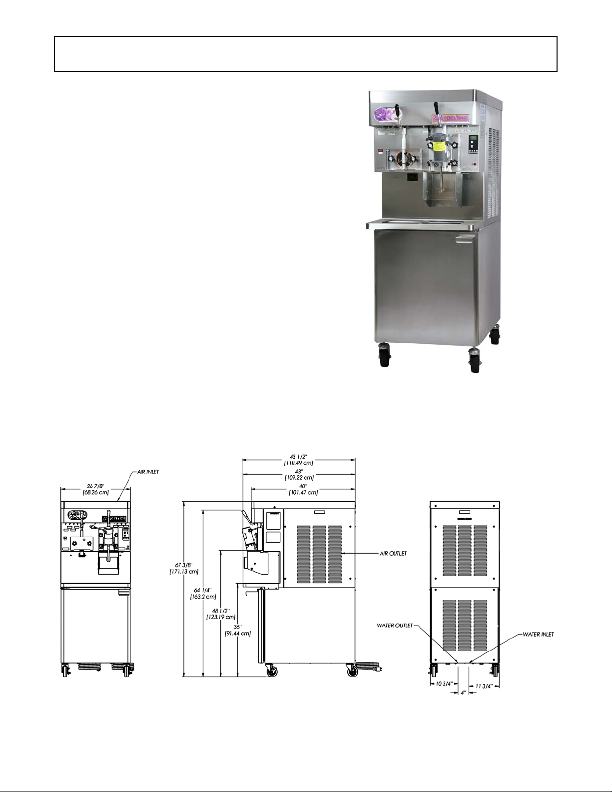
The Stoelting SU444 and U444A floor model machines are
pressure fed. They are equipped with fully automatic
controls to provide a uniform product. The SU444 and
U444A are designed to dispense soft serve product from the
left side and shake product from the right side. The SU444
has a blender attached to the front door of the shake side.
This manual is designed to assist qualified service personnel and operators with installation, operation and maintenance of the SU444 and U444A.
Figure 1-1 Model SU444 Machine
Figure 1-2 Dimensions
1
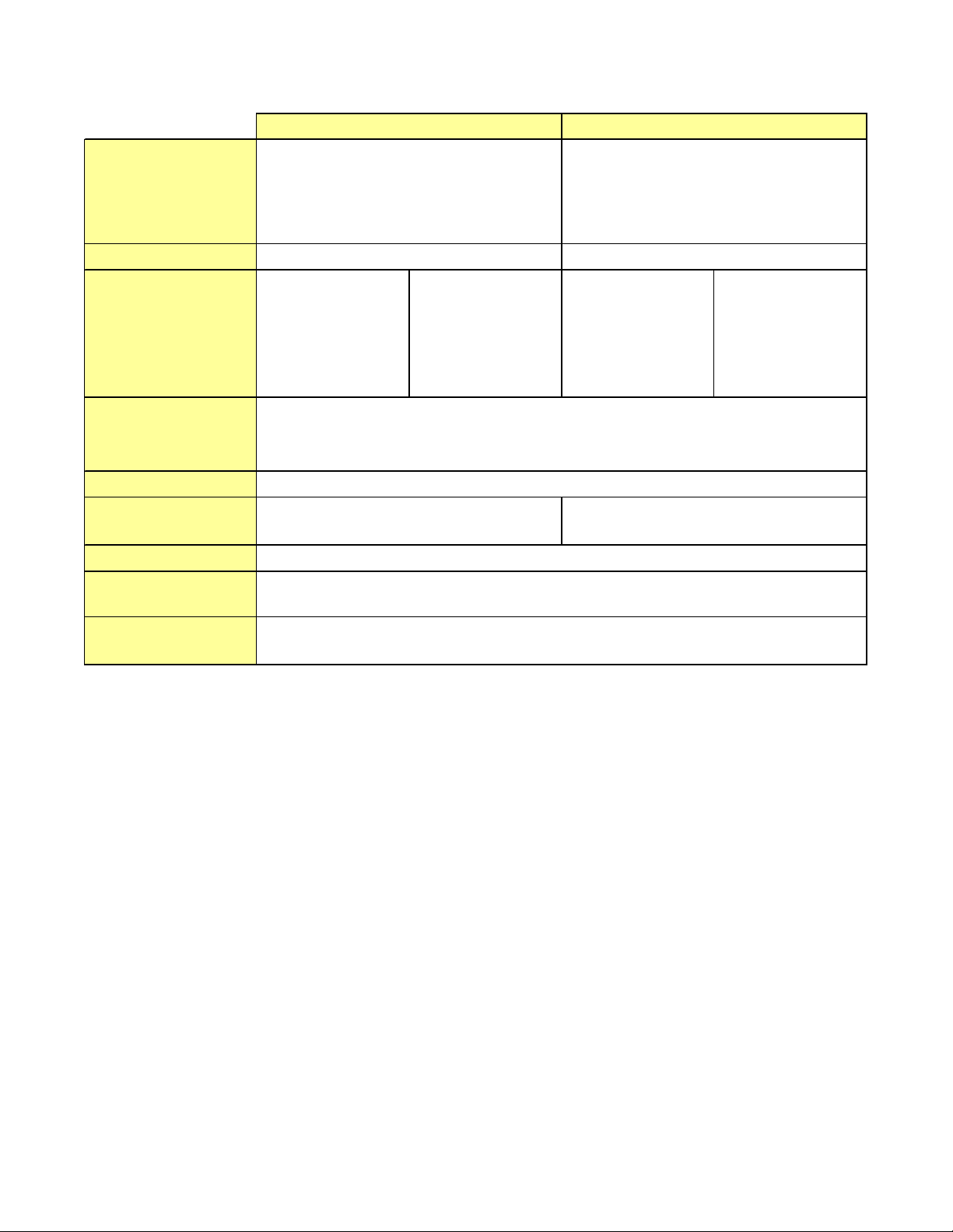
1.2 SPECIFICATIONS
Dimensions
width
height
depth
Weight
Electrical
minimum circuit
ampacity
maximum overcurrent
protection device
Compressor
Drive Motor
Cooling
Hopper Volum e
Freezing Cylinder
Volume
Production
Capacity
SU444 Water Cooled
Machine
26-7/8'' (68,3 cm)
67-3/8'' (171,1 cm)
40'' (101,6 cm ) 48'' (121,9 cm )
760 lbs (344, 7 kg)
1 PH
left right left right left right left right
wi th c r a te
34'' (86,4 cm )
78'' ( 1 98,1 cm )
908 lb s ( 411,8 kg)
3 PH
26-7/8'' (68, 3 cm)
67-3/8'' (171,1 cm)
40'' (101,6 cm)
760 lbs (344, 7 kg)
SU444 Air Co oled
Machine
1 PH
wi t h c rate
34'' (86,4 cm)
78'' (198,1 cm)
48'' (121,9 cm)
908 lbs (411, 8 kg)
3 PH
30A 22A 19A 15A 31A 23A 19A 15A
45A 35A 30A 25A 45A 35A 30A 25A
Soft Serve - 19,000 Btu/h r Scroll™ Compressor (R-404A)
Shake - 15,000 Btu/hr Scroll™ Compressor (R-404A)
Cabinet - 1,300 Btu/hr Compressor (R-134a)
Soft Ser ve - 2 hp , Shake - 3/ 4 hp
Water cool ed u nits r equ ire 1/ 2" N. P.T.
wat er and drain f ittings.
Air cool ed units re quire 6" ( 15,2 cm) air
space on both sides and back.
T w o - 8 ga l lon ( 30,28 liters )
Soft Serve - 1. 33 gallon (5.32 quart), 5, 4 liters
Sha ke - 2.1 gal l o n (8. 4 quart) , 7,95 liter s
Soft Serve - 19 GPH (71,92 liters)
Shake - 32 G PH ( 121,13 l iter s)
2
SECTION 2
INSTALLATION INSTRUCTIONS
2.1 SAFETY PRECAUTIONS
Do not attempt to operate the machine until the safety
precautions and operating instructions in this manual are
read completely and are thoroughly understood.
Take notice of all warning labels on the machine. The labels
have been put there to help maintain a safe working
environment. The labels have been designed to withstand
washing and cleaning. All labels must remain legible for
the life of the machine. Labels should be checked periodically to be sure they can be recognized as warning labels.
If danger, warning or caution labels are needed, indicate the
part number, type of label, location of label, and quantity
required along with your address and mail to:
STOELTING
A TTENTION: Customer Service
502 Hwy . 67
Kiel, Wisconsin 53042
2.2 SHIPMENT AND TRANSIT
The machine has been assembled, operated and inspected
at the factory. Upon arrival at the final destination, the
entire machine must be checked for any damage which
may have occurred during transit.
With the method of packaging used, the machine should
arrive in excellent condition. THE CARRIER IS RESPONSIBLE FOR ALL DAMAGE IN TRANSIT, WHETHER
VISIBLE OR CONCEALED. Do not pay the freight bill until
the machine has been checked for damage. Have the
carrier note any visible damage on the freight bill. If
concealed damage and/or shortage is found later, advise
the carrier within 10 days and request inspection. The
customer must place a claim for damages and/or shortages in shipment with the carrier. Stoelting, Inc. cannot
make any claims against the carrier.
2.3 MACHINE INSTALLATION
WARNING
Installation must be completed by a qualified
electrician/refrigeration specialist.
Incorrect installation may cause personal injury,
severe damage to the machine and will void factory
warranty.
Installation of the machine involves moving the machine
close to its permanent location, removing all crating,
setting in place, assembling parts, and cleaning.
A. Uncrate the machine.
B. Install the four casters. Turn the threaded end into
the machine until no threads are showing. To level,
turn out casters no more than 1/4" maximum, then
tighten all jam nuts.
C. The machine must be placed in a solid level
position.
NOTE
Accurate leveling is necessary for correct drainage
of freezing cylinder and to insure correct overrun.
D. Machines with air cooled condensers require a
minimum of 6" (15,2cm) space on all sides and
back for proper circulation.
NOTE
In order for the condenser fan motor to work the left
side needs to be connected to a power source.
E. Machines that have a water cooled condenser
require 1/2" NPT supply and drain fittings.
2.4 INSTALLING WIRING
A. Refer to the nameplate on the side panel of the
machine for specific electrical requirements. Make
sure the power source in the building matches the
nameplate requirements. Bring the wires into the
junction boxes through the access holes in the
bottom rear of the freezer.
NOTE
Three phase freezers in areas of unbalanced electrical loads require special attention when connecting input electrical power. The unbalanced leg of
power (called wild or high) must be connected to L2
in the junction box.
B. Remove the back panel and the junction box cover
located at the bottom of the machine.
C. Install permanent wiring according to local code.
D. If the line voltage is less than 215V, the fan motor
needs to be rewired. Refer to the wiring diagram for
details.
NOTE
Low incoming voltage affects the fan motor speed
and could cause high head pressure errors from the
reduced air flow. Rewiring the fan motor prevent s the
fan speed from decreasing to an unsuitable rate.
3
6" (15cm)
Figure 2-2 Mix Hose Installation
2.5 CHECK COMPRESSOR FOR PROPER
POWER (3 PHASE ONLY)
After connecting the electrical, check that the compressor
is operating in the proper direction.
A. Start a freezing cycle.
On the right side, place the Main Freezer Power
switch and Freezing Cylinder OFF/ON switch to
the ON position. Press the PUSH TO FREEZE
button.
On the left side, place the Clean/Off/Serve and the
Standby/Serve switches in the Serve position.
B. The suction line will be cold to the touch within 1
minute.
C. If it is not, disconnect power to the machine and
reverse L1 and L3 lines in the junction box.
D. After reversing the electrical lines, recheck the
suction line.
2.6 CHECK BLENDER ROTATION
After connecting the electrical, check the blender on the
right side for proper rotation.
A. Place the Blender Power Off/On switch to the ON
position.
B. With the clear swing sheild in place, move the
spigot handle to the right.
WARNING
Hazardous Moving Parts
Blender shaft and agitator can grab and cause injury . Do not operate blender without protective shield
or swing splash shield.
C. The blender should rotate clockwise looking from
the top of the blender.
D. If the rotation is counterclockwise, refer to the
wiring diagram located behind the header panel
and check the diode direction. Reverse the diode
polarity if needed.
2.7 MIX PUMP
A. MIX PUMP HOSE INSTALLATION
Follow the steps below to install the mix pump hose in the
cabinet part of the machine.
1. Turn the mix pump on. The switch is located on the
header panel.
2. Feed one end of the mix pump hose into the
entering or pickup hose side (left) of black cover
(Fig 2-2).
NOTE
Feed the tube into the clamp so the natural curve of
the tube is towards the outside of the black cover.
This prevents the hose from looping around the
black cover twice.
3. Gently push the hose into the black cover until it
begins to feed.
4
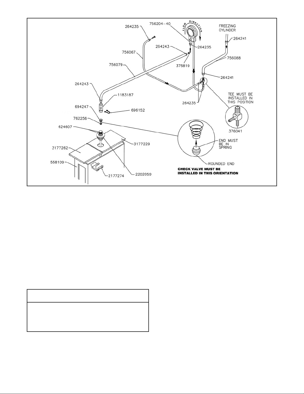
Figure 2-3 Mix Pump Connections for Standard Mix Container
4. Allow the hose to feed itself through the pump until
about 6" (15cm) remains on the entering side.
5. Turn the pump off.
6. Connect the mix pump hose to the elbow fitting
(located on the left side of the mix line manifold)
using a small hose clamp. Be careful not to twist
the mix hose.
7. Turn the pump on.
8. Allow the remaining 6" (15cm) of tubing to feed
through pump until the hose adapter prevents
further feeding.
9. Turn the pump off.
CAUTION
Risk of Product Damage
Air/Mix T ee must remain below the black cover clamp.
If the Tee is above the pump, mix may drain into the
air compressor resulting in pump damage.
10. Connect the free end of the mix pump hose to the
3-way Tee (Fig. 2-3). When all connections are
complete, the 3-way Tee must be lower than the
black pump housing.
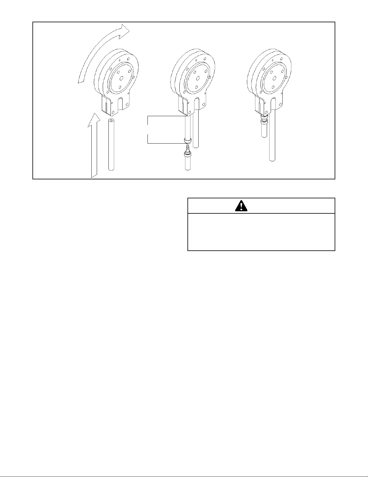
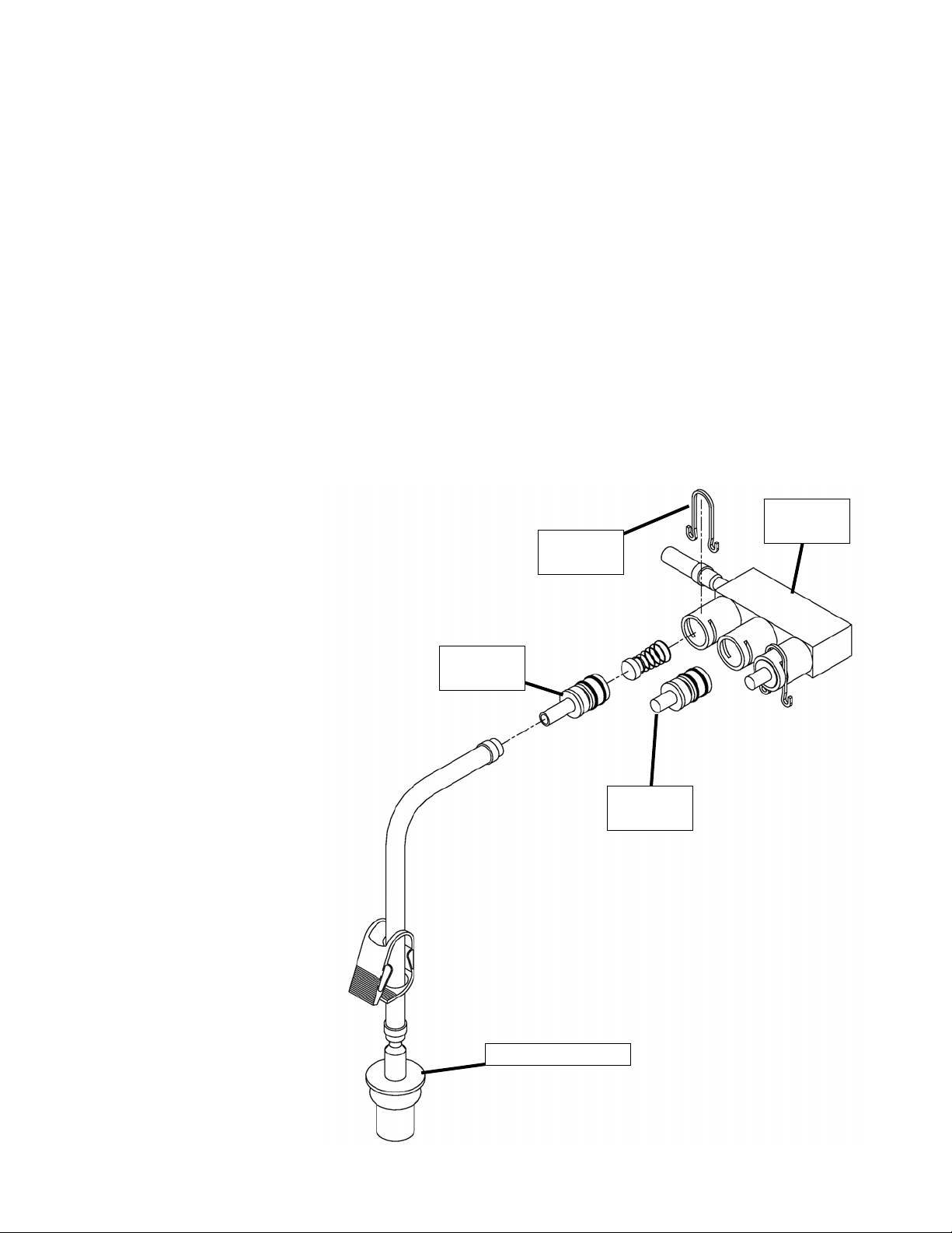
B. MIX PICKUP HOSE INSTALLATION
The machine may be connected to the standard mix
container or up to three prepacked mix bags. Follow the
instructions below that match your configuration.
Standard Connection:
1. Place the mix pickup assembly through the hole in
the cover and install the retaining clip.
2. Connect a 24" (61cm) length of 3/8" (9,5mm) ID
plastic food grade tubing to the mix pickup
assembly. Secure with a hose clamp.
3. Connect the elbow fitting to the free end of the
tubing. Connect the opposite end of the elbow to 1/
4" ID tan tubing on the left side of the pump head.
Secure with hose clamps (Fig. 2-3).
When Using Bag Connection System (BCS) with Three
Bags (optional kit):
The position of the three bags in the mix container is
important. The bag that is connected nearest the outlet of
the manifold will drain last and should be placed at the back
of the mix container. The mix low level indicator relies on
proper bag placement.
1. Connect 3/8" (9,5mm) ID plastic food grade tubing
to a bag adapter. Secure with hose clamps.
5
2. Slide the hose clip over free end of 3/8" (9,5mm) ID
plastic food grade tubing. Attach the free end of the
tubing to a manifold adapter. Secure with a large
hose clamp or equivalent.
3. Push the manifold adapter with spring and valve
into the left port (nearest the manifold outlet) of the
mix inlet manifold and secure with a retaining clip.
4. Repeat steps 1 to 3 for the middle port and for the
right port of the mix inlet manifold.
5. Place three mix bags into the mix container.
6. Connect the bag adapter attached to the left side
of the manifold (closest to the mix outlet) to the mix
bag in the back of the mix container.
7. Connect the bag adapter attached to the middle of
the manifold to the mix bag in the middle of the mix
container.
8. Connect the bag adapter attached to the right side
of the manifold (farthest from the mix outlet) to the
mix bag in the front of the mix container.
When Using Bag Connection
System (BCS) with One or Two
Bags (optional kit):
When connecting one or two bags,
the manifold adapters must be
installed closest to the manifold
outlet and the manifold plug(s)
must be placed farthest from the
manifold outlet.
1. Connect 3/8" (9,5mm) ID
plastic food grade tubing
to a bag adapter. Secure
with hose clamps.
2. Slide the hose clip over
the free end of the tubing.
Attach the free end of the
tubing to a manifold
adapter. Secure with a
large hose clamp.
3. Push the manifold
adapter with spring and
valve into the left port
(nearest the manifold
outlet) of the mix inlet
manifold and secure with
retaining clip. (See Figure
2-4).
4. If using two mix bags,
repeat steps 1 to 3 for the
middle port.
5. Install a manifold plug into
each empty inlet and
secure with a retaining
clip.
Manifold
Adapter
6. Place the mix bag(s) into the mix container.
7. Connect the bag adapter attached to the left side
of the manifold (closest to the mix outlet) to the mix
bag in the back of the mix container.
C. MIX LOW LEVEL INDICATOR ADJUSTMENT
The sensitivity of the “Mix Low” indication can be adjusted
to operator preference. If more advanced notice of low mix
is required, loosen the black adjustment knobs located on
the sensor brackets at the back of the machine cabinet and
slide the bracket upwards. If the “Mix Low” message (right
side) or flashing light (left side) appears while there is still
sufficient mix in the container, slide the bracket downward.
Be sure to tighten the adjustment knobs after properly
positioning the sensor.
Mix Inlet
Retaining
Clip
Manifold
Plug
Bag Adapter
Manifold
Figure 2-4 Bag Connection System (Optional)
6
SECTION 3
INITIAL SET-UP AND OPERATION
3.1 OPERATOR’S SAFETY PRECAUTIONS
SAFE OPERATION IS NO ACCIDENT; observe these
rules:
A. Know the machine. Read and understand the
Operating Instructions.
B. Notice all warning labels on the machine.
C. Wear proper clothing. Avoid loose fitting garments,
and remove watches, rings or jewelry that could
cause a serious accident.
D. Maintain a clean work area. Avoid accidents by
cleaning up the area and keeping it clean.
E. Stay alert at all times. Know which switch, push
button or control you are about to use and what
effect it is going to have.
F. Disconnect power for maintenance. Never attempt
to repair or perform maintenance on the machine
until the main electrical power has been
disconnected.
G. Do not operate under unsafe operating conditions.
Never operate the machine if unusual or excessive
noise or vibration occurs.
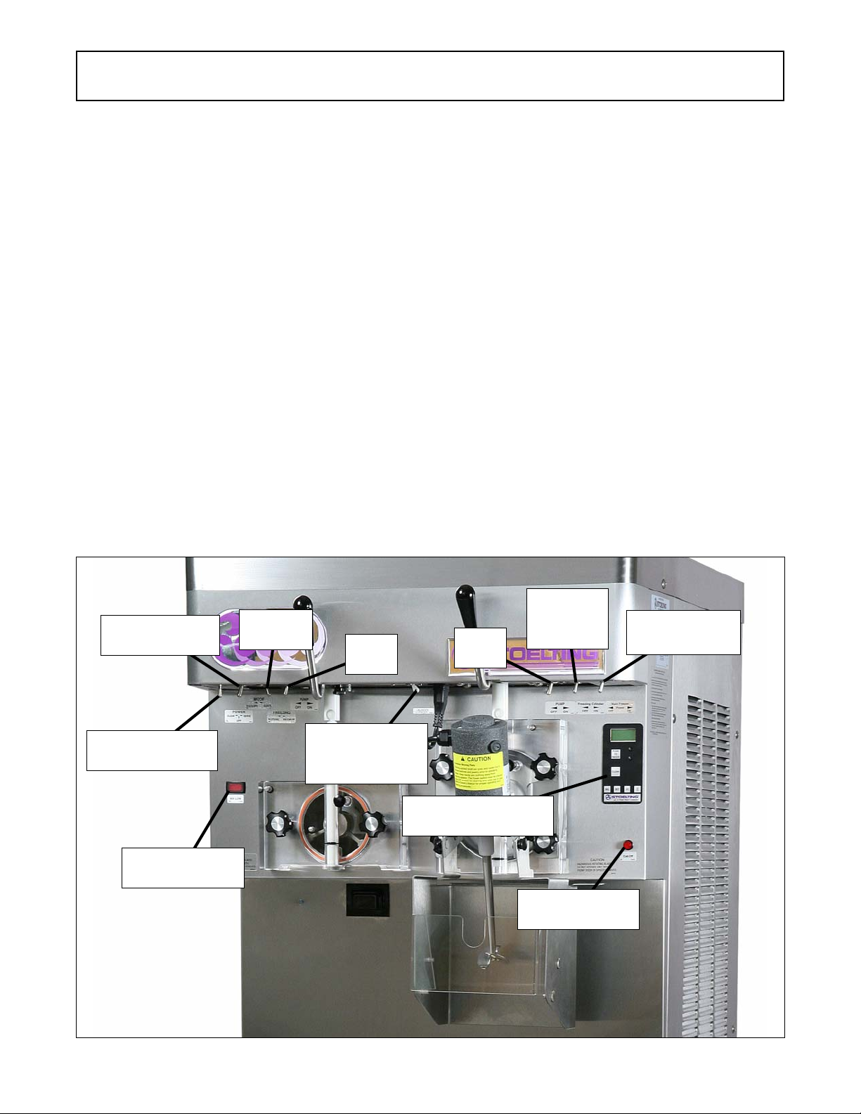
3.2 OPERATING CONTROLS AND
INDICATORS
Before operating the machine, it is required that the
operator know the function of each operating control. Refer
to Figure 3-1 for the location of the operating controls on the
machine. For the information regarding error codes displayed on the control panel, refer to the troubleshooting
section of this manual.
A. Pump Switch (Both Sides)
The pump motor switch is the toggle switch located under
the header panel. When the switch is placed in the OFF
position, the pump will not run. When the switch is placed
in the ON position, the pump will run until the preset
pressure is reached. It then cycles on and off as product is
drawn to maintain that pressure.
B. Spigot Switch (Both Sides)
The spigot switch is mounted to the spigot cam assembly
behind the header panel. When the spigot is opened to
dispense product, the spigot switch opens and the "Serve
Mode" begins.
Standby/Serve
Switch
Clean/Off/Serve
Switch
Mix Low
Indicator Light
Freezing
Switch
Pump
Off/On
Blender Power
Off/On Circuit
Breaker
Pump
Off/On
IntelliTec Control
(See Figure 3-2)
Freezing
Cylinder
Off/On
Cab Off
Indicator Light
Main Freezer
Power Off/On
Figure 3-1 SU444 Freezer Controls
7
 Loading...