

Page 1

Model SO218 / SO318
SERVICE MANUAL
Manual No. 513573 Rev.3
Page 2

Page 3

This manual provides basic information about the machine. Instructions and suggestions are
given covering its operation and care.
The illustrations and specifi cations are not binding in detail. We reserve the right to make
changes to the machine without notice, and without incurring any obligation to modify or provide new parts for machines built prior to date of change.
DO NOT ATTEMPT to operate the machine until instructions and safety precautions in this
manual are read completely and are thoroughly understood. If problems develop or questions
arise in connection with installation, operation, or servicing of the machine, contact Stoelting.
stoeltingfoodservice.com
Stoelting Foodservice Equipment
502 Highway 67
Kiel, WI 53042-1600
U.S.A.
Main Tel: 800.558.5807
Fax: 920.894.7029
Customer Service: 888.429.5920
Fax: 800.545.0662
Email: foodservice@stoelting.com
© 2014 PW Stoelting, LLC
Page 4

A Few Words About Safety
Safety Information
Read and understand the entire manual before
operating or maintaining Stoelting equipment.
This manual provides the operator with information
for the safe operation and maintenance of Stoelting
equipment. As with any machine, there are hazards
associated with their operation. For this reason safety
is emphasized throughout the manual. To highlight
specifi c safety information, the following safety defi ni-
tions are provided to assist the reader.
The purpose of safety symbols is to attract your attention to possible dangers. The safety symbols, and
their explanations, deserve your careful attention
and understanding. The safety warnings do not by
themselves eliminate any danger. The instructions
or warnings they give are not substitutes for proper
accident prevention measures.
If you need to replace a part, use genuine Stoelting
parts with the correct part number or an equivalent
part. We strongly recommend that you do not use
replacement parts of inferior quality.
Safety Alert Symbol:
This symbol Indicates danger, warning or caution.
Attention is required in order to avoid serious personal injury. The message that follows the symbol
contains important information about safety.
Signal Word:
Signal words are distinctive words used throughout
this manual that alert the reader to the existence and
relative degree of a hazard.
WARNING
The signal word “WARNING” indicates a potentially
hazardous situation, which, if not avoided, may result
in death or serious injury and equipment/property
damage.
CAUTION
The signal word “CAUTION” indicates a potentially
hazardous situation, which, if not avoided, may result
in minor or moderate injury and equipment/property
damage.
CAUTION
The signal word “CAUTION” not preceded by the
safety alert symbol indicates a potentially hazardous
situation, which, if not avoided, may result in equipment/property damage.
NOTE (or NOTICE)
The signal word “NOTICE” indicates information or
procedures that relate directly or indirectly to the
safety of personnel or equipment/property.
Page 5

TABLE OF CONTENTS
SECTION DESCRIPTION PAGE
1. INTRODUCTION
1.1 Remote Possibilities ...................................................................................................................... 1
1.2 Features ........................................................................................................................................ 1
1.3 Dispenser Specifications................................................................................................................ 2
2. INSTALLATION INSTRUCTIONS
2.1 Safety Precautions........................................................................................................ ................. 3
2.2 Shipment and Transit ..................................................................................................................... 3
2.3 Freezer Installation...................................................................................................... ................... 3
2.4 Installing Permanent Wiring............................................................................................................ 4
3. INITIAL SET-UP AND OPERATION
3.1 Operator's Safety Precautions........................................................................................................ 5
3.2 Operating Controls and Indicators .................................................................................................. 5
3.3 Disassembly of Freezer Parts ........................................................................................................ 5
3.4 Cleaning the Freezer Parts............................................................................................................. 6
3.5 Sanitize Freezer and Freezer Parts................................................................................................ 6
3.6 Assembly of Freezer ...................................................................................................................... 6
3.7 Sanitizing ....................................................................................................................................... 7
3.8 Initial Freeze Down and Operation .................................................................................................. 8
3.9 Removing Product .......................................................................................................................... 8
3.10 General Operation Information ....................................................................................................... 9
4. PREVENTATIVE MAINTENANCE
4.1 Routine Cleaning ............................................................................................................................ 11
4.2 Preventative Maintenance............................................................................................................... 11
4.3 Extended Storage .......................................................................................................................... 11
4.4 Consistency Adjustment ................................................................................................................ 11
5. REFRIGERATION SYSTEM
5.1 Refrigeration System...................................................................................................................... 13
5.2 Compressor ................................................................................................................................... 13
5.3 Condenser...................................................................................................................................... 14
5.4 Evaporator...................................................................................................................................... 14
5.5 Hopper ........................................................................................................................................... 16
5.6 Capillary Tube ................................................................................................................................ 18
6. ELECTRICAL
6.1 Electrical........................................................................................................................................ 19
6.2 Front Electrical Box ....................................................................................................................... 19
6.3 Compressor Electrical Box............................................................................................................. 21
6.4 Major Component Replacement ..................................................................................................... 21
7. TROUBLESHOOTING .......................................................................................................................... 27
8. REPLACEMENT PARTS INFORMATION
8.1 Ordering Parts................................................................................................................................ 29
9. REFERENCE DRAWINGS .................................................................................................................... 31
10. ACCESSORIES
10.1 Fill-o-matic II ................................................................................................................................ 45
10.2 Fill-o-matic III................................................................................................................................ 49
11. ADDENDUM .......................................................................................................................................... 53
Page 6

LIST OF ILLUSTRATIONS
FIGURE TITLE PAGE
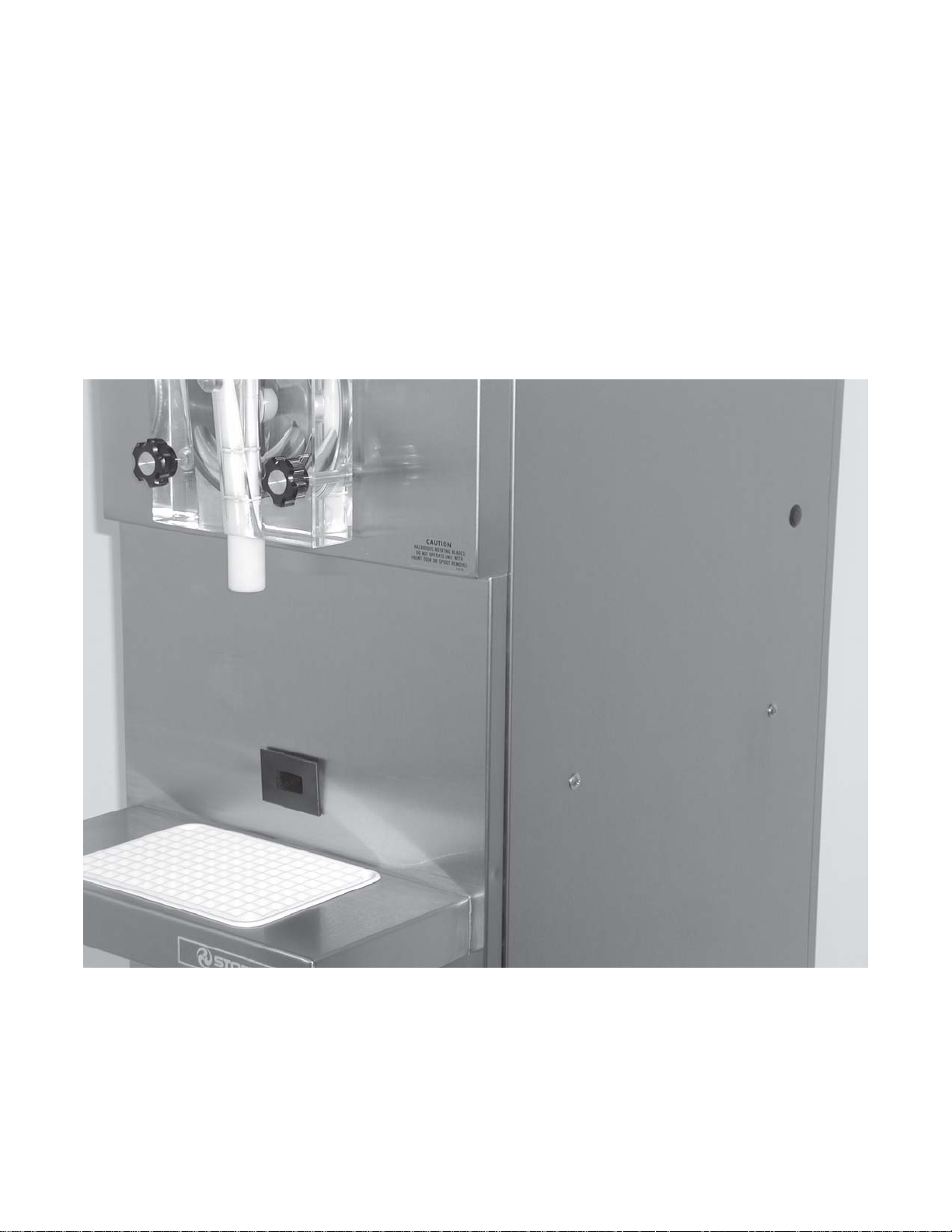
1 Model SO218/318.................................................................................................. 1
2 Dispenser Specifications ....................................................................................... 2
3 Leveling Unit .......................................................................................................... 3
4 Controls................................................................................................................. 5
5 Disassembling Freezer .......................................................................................... 6
6 Front Door and Auger Assembly............................................................................ 6
7 Rear Seal Assembly.............................................................................................. 6
8 Retainer Clip .......................................................................................................... 7
9 Consistency Control Knob ..................................................................................... 8
10 Nameplates ...........................................................................................................13
11 Compressor Terminal Cover Removal .....................................................................13
12 Compressor Connections.......................................................................................13
13 Ohm Meter Connection..........................................................................................14
14 Condenser .............................................................................................................14
15 Access Ports .........................................................................................................15
16 TXV........................................................................................................................15
17 Heat Sink ..............................................................................................................15
18 Drier.......................................................................................................................16
19 EPR & Access Port...............................................................................................16
20 EPR Valve Adjustment ..........................................................................................17
21 EPR Heat Sink ......................................................................................................17
22 Filter Drier..............................................................................................................18
23 Drier Cap. Tube Assembly.....................................................................................18
24 Electrical Panel .....................................................................................................19
25 Switch Removal ..................................................................................................... 19
26 Light Bulb Replacement.........................................................................................19
27 Safety Switch ........................................................................................................20
28 Liquid Level Control................................................................................................20
29 Pump Relay...........................................................................................................20
30 Torque Switch........................................................................................................21
31 Compressor Contactor...........................................................................................21
32 Fan Motor..............................................................................................................21
33 Condenser .............................................................................................................22
34 Electrical Wires .....................................................................................................22
35 Compressor ...........................................................................................................23
36 Torque Spring ........................................................................................................23
37 Torque Switch Bracket...........................................................................................24
38 Belt Tensioner........................................................................................................24
39 Bearing Assembly .................................................................................................24
Page 7

SECTION 1
INTRODUCTION
1.1 REMOTE POSSIBILITIES
The Stoelting Optima delivers frozen drink profits by the pitcher. The Model SO218/318 is a high-volume
producer of ready-to-serve frozen cocktails or frozen neutral base for those special drink recipes. From an
extra-small space, the Optima’s compact design and high capacity output will give you extra-large profits.
1.2 FEA TURES
High Capacity
- 15-18 gallons per hour output
- Thick, stackable slush for
post-mixing
- Or, ready-to-serve pre-mixed
products
High Efficiency Evaporator/
Auger
- Stainless steel construction
- Long life auger blades
- Quiet, smooth operation
- 8 qt. freezing cylinder capacity
Figure 1. Model SO218/318
Consistency Control
- Adjustable for thick or thin
products
- Sensitive to product demand
- 24 volt control circuits
1
Dispensing Head Door
- ”No-Freeze” design prevents
blockages
- Fast dispense for quick fill of
pitchers
- Controlled dispense for drinks
by the glass
- Convenient pull-type handle
- Attractive, clear, see-thru
design
- Visible, moving product for
merchandising appeal
Page 8
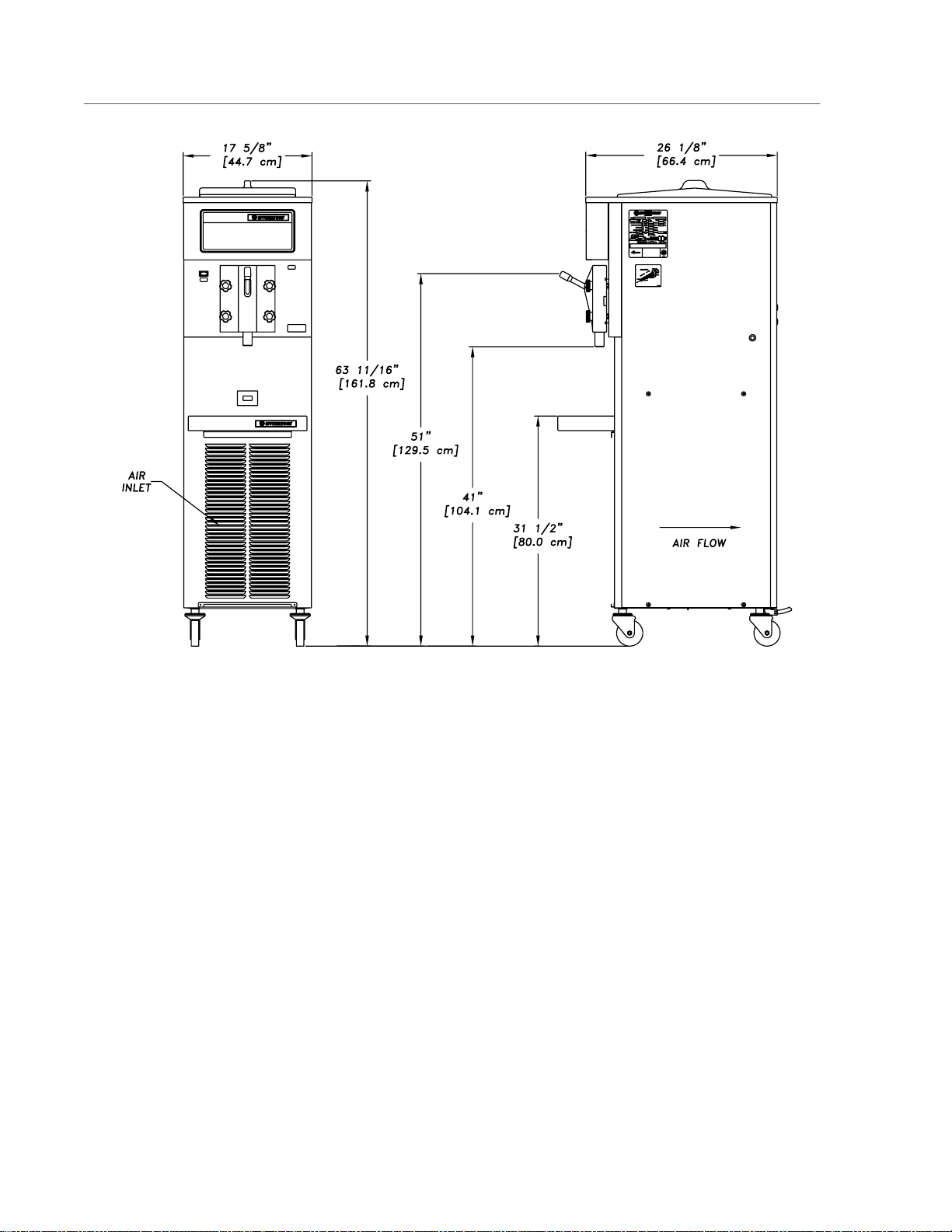
1.3 DISPENSER SPECIFICATIONS
Figure 2. Dispenser Specifications
Electrical Refrigeration Crated Dimensions Dimensions
208/230/60/1 HFC-404A environmentally- Width: 25" (63.5cm) Width: 17-5/8"(44.7cm)
20 amp circuit & plug friendly refrigerant Depth: 51" (129.5cm) Depth: 26-1/8"(66.4cm)
12 running amps SO318 Air-cooled or water- Height: 66" (167.6cm) Height: 63-1 1/16"(161.8cm)
cooled, self contained Weight: 410lbs.(186kg) w/casters
SO218 Air-cooled or water- Weight: 315lbs.(142.9kg)
cooled, self contained
2
Page 9
SECTION 2
INSTALLATION INSTRUCTIONS
2.1 SAFETY PRECAUTIONS
Do not attempt to operate the freezer until the safety
precautions and operating instructions in this manual are
read completely and are thoroughly understood.
Take notice of all warning labels on the freezer. The
labels have been put there to help maintain a safe
working environment. The labels have been designed to
withstand washing and cleaning. All labels must remain
legible for the life of the freezer. Labels should be
checked periodically to be sure they can be recognized
as warning labels.
If danger, warning or caution labels are needed, indicate
the part number, type of label, location of label, and
quantity required along with your address and mail to:
STOELTING, LLC
ATTENTION: Customer Service
502 Hwy. 67
Kiel, Wisconsin 53042
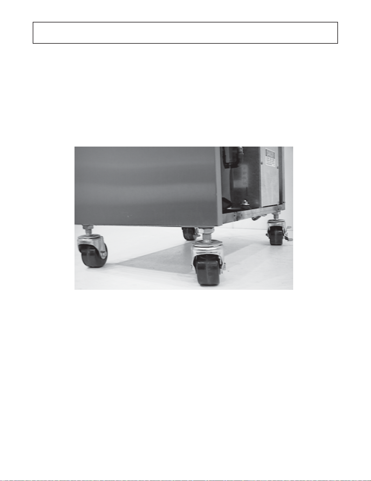
Figure 3. Leveling Unit
2.2 SHIPMENT AND TRANSIT
The freezer has been assembled, operated and inspected at the factory. Upon arrival at the final destination, the complete freezer must be checked for any
damage which may have occurred during transit.
With the method of packaging used, the freezer should
arrive in excellent condition. THE CARRIER IS RESPONSIBLE FOR ALL DAMAGE IN TRANSIT,
WHETHER VISIBLE OR CONCEALED. Do not pay the
freight bill until the freezer has been checked for damage. Have the carrier note any visible damage on the
freight bill. If concealed damage and/or shortage is found
later, advise the carrier within 10 days and request
inspection. The customer must place claim for damages
and/or shortages in shipment with the carrier. Stoelting,
Inc. cannot make any claims against the carrier.
2.3 FREEZER INSTALLATION
Installation of the freezer involves moving the freezer close
to its permanent location, removing all crating, setting in
place, assembling parts, and cleaning.
A. Uncrate the freezer.
B. The freezer must be placed in a solid level position. To
level adjust casters.
C. The freezer is equipped with an air cooled condenser
and requires correct ventilation; the front is the intake
and the back is the discharge. Both front and back
require 3" clearance for proper operation.
D. Place all switches in the OFF position.
3
Page 10

E. Connect the power cord. The plug is designed for 208/
230 volt/20 amp duty. The unit must be connected to
a properly grounded receptacle. The electrical cord
furnished as part of the freezer has a three prong
grounding type plug. The use of an extension cord is
not recommended. If one must be used, use one with
a size 12 gauge or heavier with a ground wire. Do not
use an adaptor to get around grounding requirements.
CAUTION
DO NOT ALTER OR DEFORM PLUG IN ANY WAY!
F. Install the drip tray, cover and other miscellaneous
parts on the freezer.
2.4 INSTALLING PERMANENT WIRING
If permanent wiring is required by local codes, the following procedure must be performed.
WARNING
DISCONNECT FREEZER FROM THE SOURCE
OF ELECTRICAL SUPPL Y BEFORE SERVICING.
A. Remove the right side panel and electrical box cover
to gain access to the power cord connection.
B. Disconnect the black and white wires from the termi-
nal block (L1 and L2). Disconnect the green ground
wire from the grounding screw.
C. Remove the strain relief connector from the bottom of
the freezer base.Remove the power cord.
D. Install permanent wiring according to local code.
E. Connect black wire to L1 on the terminal block.
Connect the white wire to L2 on the terminal block.
Connect the green or yellow and green striped
ground wire to the grounding screw.
F. Replace all panels.
4
Page 11
SECTION 3
INITIAL SETUP AND OPERATION
3.1 OPERATOR'S SAFETY PRECAUTIONS
SAFE OPERA TION IS NO ACCIDENT; Observe these
rules:
A. Know the freezer. Read and understand the
Operating Instructions.
B. Notice all warning labels on the freezer.
C. Wear proper clothing. Avoid loose fitting garments,
and remove watches, rings or jewelry which could
cause a serious accident.
D. Maintain a clean work area. Avoid accidents by
cleaning up the area and keeping it clean.
E. Stay alert at all times. Know which switch, push
button or control you are about to use and what
effect it is going to have.
F. Disconnect electrical cord for maintenance.
Never attempt to repair or perform maintenance on
the freezer until the main electrical power has been
disconnected.
G. Do not operate under unsafe operating condi
tions. Never operate the freezer if unusual or excessive noise or vibration occurs.
3.2 OPERATING CONTROLS AND INDICATORS
Before operating the freezer, it is required that the
operator know the function of each operating control.
Refer to Figure 4 for the location of the operating
controls on the freezer.
C. Mix Low Light
The Mix Low light will illuminate when you are low on
mix.
CAUTION
DO NOT OPERA TE FREEZER WHEN THE LOW
MIX LIGHT IS ILLUMINATED OR DAMAGE TO
THE FREEZER COULD RESULT.
D. Front Door Interlock Switch
When the front door is removed the freezer will not
run. When the front door is installed a stanless steel
peg will close the switch and the freeezer will run.
E. High Pressure Cutout Switch (water cooled only)
The high pressure cutout switch (high limit control) is
located on the lower left side. When the switch is
tripped nothing will run. Push to reset.
Pump Off/On
Switch
ËË
Ë
ËË
ÇÇ
Ç
ÇÇ
Mix Low
Light
Front Door Interlock Switch
ÇÇ
Ç
ÇÇ
ÇÇ
Ç
ÇÇ
Clean/Off/Serve
Switch
A. Pump OFF/ON Switch (Model SO318 only)
The pump OFF/ON Switch is a two position switch.
In the OFF position the pump will not run. In the ON
position the pump will run until the proper liquid level
is reached, then stop. If the hopper does not fill
completely , place the switch in the OFF position,
then back to ON to continue filling.
WARNING
THE CLEAN/OFF/SERVE SWITCH MUST BE PLACED
IN THE OFF POSITION WHEN DISASSEMBLING FOR
CLEANING OR SERVICING. THE FREEZER MUST BE
DISCONNECTED FROM ELECTRICAL SUPPLY BEFORE REMOVING ANY ACCESS P ANEL.
B. CLEAN/OFF/SERVE Switch
The CLEAN/OFF/SERVE switch is a three position
toggle and refrigeration switch used to control the
operation of the agitator. When the switch is placed
in the CLEAN position, the agitator will rotate.
When the switch is placed in the OFFposition,
nothing will operate. When the switch in placed in
the SERVE position, the agitator and refrigeration
system will run until proper consistency is reached
then stop.
Figure 4. Controls
3.3 DISASSEMBL Y OF FREEZER P ARTS
CAUTION
PLACE THE CLEAN/OFF/SERVE SWITCH IN THE
OFF POSITION BEFORE DISASSEMBLING FOR
CLEANING OR SERVICING.
Inspection for worn or broken parts should be made at
every disassembly of the freezer for cleaning or other
purposes. All worn or broken parts should be replaced
to ensure safety to both the operator and the customer
and to maintain good freezer performance and a quality
product. Frequency of cleaning must comply with the
local health regulations.
T o disassemble the freezer , refer to the following steps:
A. Disconnect hose from hopper cover (Model SO318
only).
B. Remove hopper cover.
5
Page 12
C. Remove retaining clip and adaptor (Model SO318
only).
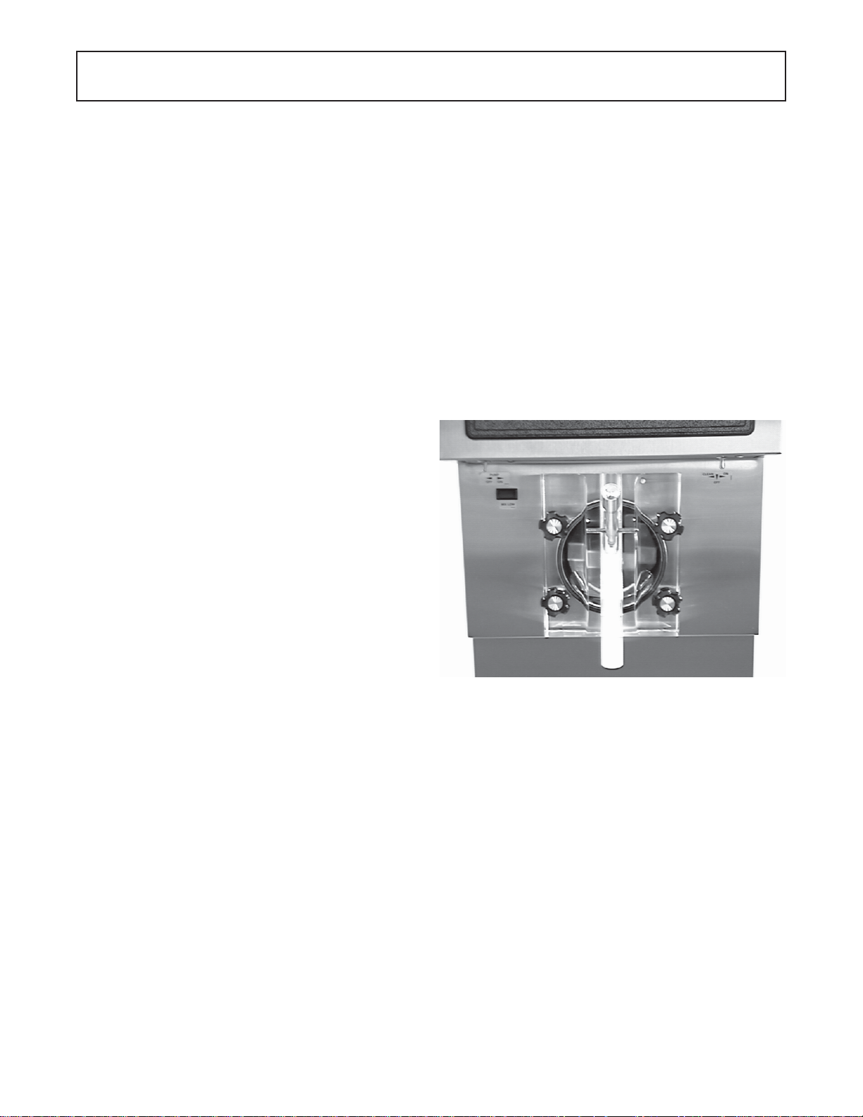
D. Remove the front door by turning off the knobs, and
then pull the front door off the studs.
Figure 5. Disassembling Freezer
E. Remove the spigot body from the front door bypu lling
the retaining pin out of the spigot handle. Push the
spigot body thru the bottom of the front door.
SOFT RUBBER
SURFACE
Figure 7. Rear Seal Assembly
3.4 CLEANING THE FREEZER PARTS
Place all loose parts in a pan or container and take to
the wash sink for cleaning. To clean freezer parts refer
to the following steps:
A. Place all parts in warm mild detergent water and
clean with brushes provided. Rinse all parts with
clean hot water.
DO NOT DAMAGE PARTS BY DROPPING OR
ROUGH HANDLING.
HARD CARBON
SURFACE
CAUTION
F. Remove the agitator assembly from the freezer. Pull
the agitator assembly out of the freezer barrel.
G. Keep the rear of the agitator assembly tipped up
once it is clear of the freezer barrel to avoid dropping
rear seal.
H. Remove the front agitator support bearing and the
two agitator blades.
I. Remove the rear seal assembly .
J. Wipe socket lubricant from the drive end (rear) of the
agitator with a cloth or paper towel.
K. Remove all “O” Rings.
W ARNING
DO NOT USE ANY TYPE OF SHARP OBJECT TO
REMOVE THE “O” RINGS.
B. Wash the freezer barrel with warm detergent water
and brushes provided.
C. The exterior should be kept clean at all times to
perserve the lustre of the stainless steel. A mild
alkaline cleaner is recommended. Use a soft cloth or
sponge to apply the cleaner.
D. Remove the drip tray insert and drain tray. Clean with
a soap solution. Rinse with clean hot water.
3.5 SANITIZE FREEZER AND FREEZER P ARTS
A. Use a sanitizer mixed according to manufacturer’s
instructions to provide a 100 parts per million
strength solution. Mix sanitizer in quantities of no
less than 2 gallons (7.5 liters) of 120°F water. Allow
the sanitizer to contact the surfaces to be sanitized
for 5 minutes. Any sanitizer must be used only in
accordance with the manufacturer’s instructions.
B. Place all parts in the sanitizing solution, then remove
and let air dry .
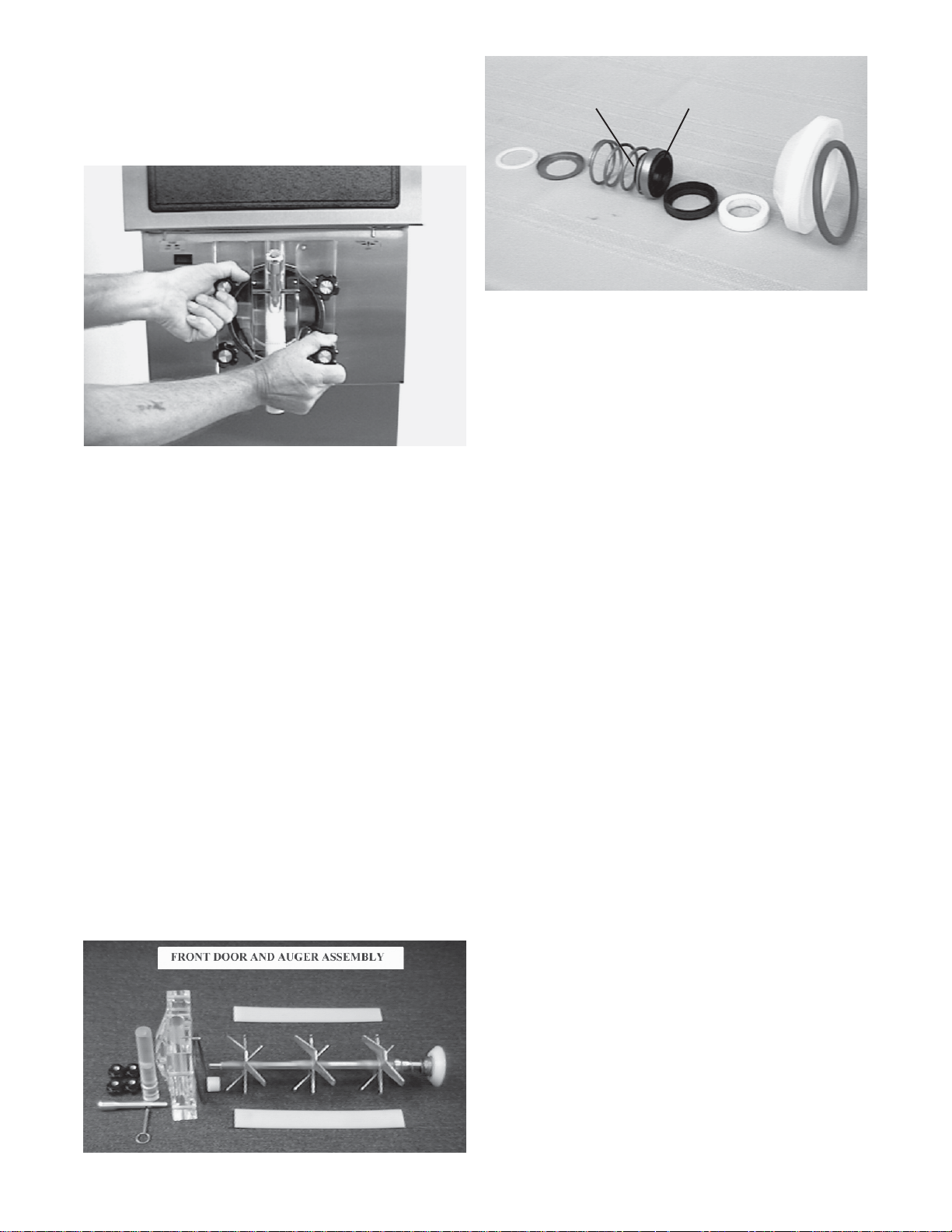
Figure 6. Front Door and Auger Assembly
3.6 ASSEMBL Y OF FREEZER
T o assemble the freezer part s, refer to the following
steps:
NOTE
Petro-Gel sanitary lubricant or equivalent must be
used when lubrication of parts is specified.
6
Page 13

NOTE
The United Sates Department of Agriculture and the
Food and Drug Administration require that lubricants
used on food processing equipment be certified for
this use. Use lubricants only in accordance with
the manufacturer’s instructions.
A. Assemble spigot “O” Rings onto parts dry , without
lubrication. Then apply a thin film of sanitary
lubrication to exposed surfaces of the “O” Rings.
K. Install hopper cover.
L. Connect mix hose to hopper cover (Model SO318
only).
3.7 SANITIZING
Sanitizing must be done after the freezer is clean and
just before filling with mix. Sanitizing the night before
is not effective. However, you should always clean the
freezer and parts after using it.
B. Assemble the rear seal assembly onto the agitator.
Be sure the “O” Ring is in place before installing
the rear seal. Do not lubricate.
C. Lubricate the agitator drive (rear) with a small
amount of white socket lubricant. A small container
of socket lubricant is shipped with the freezer.
D. Install the two plastic agitator blades onto the
agitator. Install front agit ator bearing to the door.
E. Push the auger into the freezer barrel and rotate
slowly until the agitator engages the drive socket.
F. Install the spigot body with “O” Rings into the front
door from the bottom. Push straight up until the
spigot is in place. Place the spigot handle into the
spigot and insert the retainer pin.
G. Install door “O” Ring after lubricating.
H. Install the front door on the freezer.
I. Install the knobs on the freezer studs.
CAUTION
FINGER TIGHTEN THE KNOBS EVENL Y . DO NOT
OVER-TIGHTEN KNOBS.
WARNING
THE UNITED ST ATES DEP ARTMENT OF AGRICUL TURE AND FOOD AND DRUG ADMINISTRATION REQUIRE THAT ALL CLEANING AND SANITIZING SOLUTIONS USED WITH FOOD PROCESSING EQUIPMENT BE CERTIFIED FOR THIS
USE. USE “STERA-SHEEN” OR EQUIVALENT.
When sanitizing the freezer, refer to local sanitary
regulations for applicable codes and recommended
sanitizing products and procedures. The frequency of
sanitizing must comply with local health regulations.
Mix sanitizer according to manufacturer’s instructions
to provide a 100 parts per million strength solution. Mix
sanitizer in quantities of no less than 2 gallons (7.5
liters) of 120°F water. Allow sanitizer to contact the
surfaces to be sanitized for 5 minutes. Any sanitizer
must be used only in accordance with the
manufacturer’s instructions.
NOTE
Stoelting, Inc. has found that STERA-SHEEN
GREEN LABEL SANITIZER AND CLEANER does
an effective job of properly sanitizing and cleaning a
soft serve freezer. We therefore include a sample
with each new freezer. For further information read
the directions on the packet. Other products may
be as effective.
Look for the proper seal between the freezer barrel door,
“O” Ring, and front door.
J. Install hose adaptor onto hopper cover and secure
with retainer clip (SO318 only). Figure 8.
Figure 8. Retainer Clip
CAUTION
PROLONGED CONTACT OF SANITIZER WITH
FREEZER MA Y CAUSE CORROSION OF ST AINLESS STEEL P ARTS.
In general, sanitizing may be conducted as follows:
A. Prepare 4 gallons (15 liters) of sanitizing solution
following manufacturer’s instructions, then pour into
hopper (pump thru auto fill, SO318 only).
B. Place the CLEAN/OFF/SERVE switch in the CLEAN
position. Check for leaks around the front door seal.
C. After five minutes, open spigot to drain sanitizing
solution. When solution has drained, place the
CLEAN/OFF/SERVE switch in the OFF position.
Allow the freezer barrel to drain completely .
7
Page 14
3.8 INITIAL FREEZE DOWN AND OPERA TION
This section covers the recommended operating
procedures to be followed for the safe operation of the
freezer.
A. Sanitize just prior to use.
B. Place the CLEAN/OFF/SERVE switch in the OFF
position.
D. Place the CLEAN/OFF/SERVE switch in the
SERVE position. The product will be ready to serve
in about 15 minutes.
3.9 REMOVING PRODUCT
Before disassembly, all product must be removed.
A. Open spigot and completely drain freezer.
C. With the spigot open, pour one cup of mix into the
hopper. Allow approximately 8 oz. of sanitizing
solution and mix to drain out. Close the spigot and
fill the hopper with mix.
B. Prepare not less than 3 gallons of warm detergent
water and pour into hopper (pump thru auto fill
SO318 only).
C. Use a brush to clean the hopper then completely
drain freezer.
ÊÊ
Ê
ÊÊ
Remove plug to
access consistency
adjustment screw
Figure 9. Consistency Control
8
Page 15

3.10 GENERAL OPERA TION INFORMA TION
The SO218/318 is a cocktail/slush freezer . It is available in 208-230 volt, either air-cooled or water-cooled.
The air-cooled version has front-to-back airflow requiring three inches of air space in the front and back for
proper refrigeration. This unit is not supplied with a pump, however, S toelting does offer the Fill-O-Matic II
(electric) and Fill-O-Matic III (gas) pumps FOR THE SO318. This freezer is intended for use with non-dairy
products only and will produce 15-18 GPH.
1. Filling
T o fill the freezer , pour mix into hopper until full. To fill freezers with the optional Fill-O-Matic pump, connect
the pump and turn the fill switch on. This will open the solenoid valve and the freezer will begin to fill. The
liquid level control circuit is designed with a fill timer. This timer is designed to shut the compressor off if
the top level probe is not satisfied before the timer expires. If the top level probe is not satisfied before the
timer times out, it locks the compressor out and freezing will not occur, if this happens, turn the fill switch
off and then back on, this will reset the timer .
2. Operation
Once the freezer is full of mix, turn the clean-off-serve switch to the “serve” position. The drive motor will
start immediately . The compressor utilizes a 10 second delay-on-make / delay-on-break timer therefore,
the compressor will start 10 seconds later. The compressor will continue to run until the drive motor torque
switch is satisfied, then after a 10 second delay stop. The drive motor runs continuously in the “serve” or
“clean” switch positions. There is no night mode or standby mode. If product is left in the freezer overnight
we recommend to simply turn the freezer off. Do not run the freezer in “clean” overnight. Freeze down time
will typically be 6-10 minutes depending on the type of product used and the starting product temperature.
3. Pump Operation
When the mix level in the hopper drops below the bottom level probe, the solenoid valve opens and the
pump begins to fill until the top level probe is satisfied. When satisfied, the solenoid valve closes, and
pump will continue to run until shut off pressure is reached. The electric pump will run until the pressure
reaches the cut-out pressure of the pump. A gas pump will continue to run until the pressure in the mix line
equals the gas pressure of the pump. If you wish to use the product in the hopper prior to cleaning, turn the
pump off and turn the freezer fill switch off. This will disable the fill timer and allow the compressor to
continue to run. Be cautioned that once the hopper is empty , the barrel could freeze up. Only run the
freezer until the hopper is empty or damage may occur.
4. Fill Timer Operation
The timer has ten dip switches, all switches placed in the “on” position are added together to make up the
total time delay. This freezer leaves the factory with 64, 128 and 256 in the “on” position, this is a total of
448 seconds. The preset time should be enough to fill the hopper up to the top level probe. Fill time may be
dependent on what style pump is employed. The purpose of the timer is to disable the compressorif the
mix supply runs out. When the timer expires, the mix low light will illuminate. If the mix low light is
illuminated, the compressor is locked out of the electrical circuit and will not run. It may be necessary to
change the timer settings to more closely match the pumping capacity of your pump.
9
Page 16

10
Page 17

SECTION 4
PREVENTIVE MAINTENANCE
4.1 ROUTINE CLEANING
T o remove spilled or dried mix from the freezer exterior ,
simply wash in the direction of the finish with warm
soapy water and wipe dry . Do not use highly abrasive
materials as they will mar the finish.
4.2PREVENT ATIVE MAINTENANCE
It is recommended that a maintenance schedule be
followed to keep the freezer clean and operating properly.
W ARNING
NEVER ATTEMPT TO REPAIR OR PERFORM
MAINTENANCE ON FREEZER UNTIL THE MAIN
ELECTRICAL POWER HAS BEEN DISCONNECTED.
A. Daily
1. The exterior should be kept clean at all times to
preserve the lustre of the stainless steel. A mild
alkaline cleaner is recommended. Use a soft cloth or
sponge to apply the cleaner.
B. Weekly
2. If the condenser is dirty, using compressed air or
CO2 tank, blow out the dirt from the fan side of the
condenser.
3. An alternative method of cleaning the condenser is to
use a condenser brush and vacuum.
NOTE
If the condenser is not kept clean, loss of refrigeration efficiency will result, causing extended run time
or soft product consistency .
4.3 EXTENDED STORAGE
Refer to the following steps for storage of the freezer
over any long period of shutdown time:
A. Turn CLEAN/OFF/SERVE switch to the OFF
position.
B. Disconnect (unplug) from the electrical supply
source.
C. Clean thoroughly with a warm detergent all parts that
come in contact with the mix. Rinse in clear water
and dry all parts. Do not sanitize.
1. Check “O” Rings and rear seal for excessive wear
and replace if necessary.
2. Remove the drip tray and insert. Clean the drip
tray and insert and front of the freezer with a soap
solution.
C. Monthly
CAUTION
THE FREEZER HAS AN AIR COOLED CONDENSER AND MUST HA VE PROPER AIR CIRCULA TION. FAILURE TO CLEAN THE CONDENSER
ON A REGULAR BASIS MAY RESULT IN SERIOUS FREEZER DAMAGE AND COULD VOID
FREEZER WARRANTY .
1. Visually inspect the condenser for dirt by shining a
light through the coil from the fan side of the condenser.
NOTE
Do not let the cleaning or sanitizing solution stand
in the hopper or in the freezer barrel during the shutdown period.
D. Remove, disassemble, and clean the front door, and
agitator parts. Place the agitator blades and the front
agitator support bearing in a plastic bag with a moist
paper towel to prevent them from becoming brittle.
4.4 CONSISTENCY ADJUSTMENT
The consistency adjustment knob is located behind the
right side panel near the back. Remove black plug to
access. T o adjust use a straight bladed screwdriver .
Turn clockwise for a thicker product and counterclockwise for a thinner product. Allow 15-30 minutes for the
product to change consistency .
11
Page 18

12
Page 19
SECTION 5
REFRIGERATION SYSTEM
5.1 REFRIGERATION SYSTEM
The refrigeration system is a dual purpose system. The
system is designed to operate the hopper and the evaporator simultaneously at different temperatures. The system is designed for efficient use with R404A as the
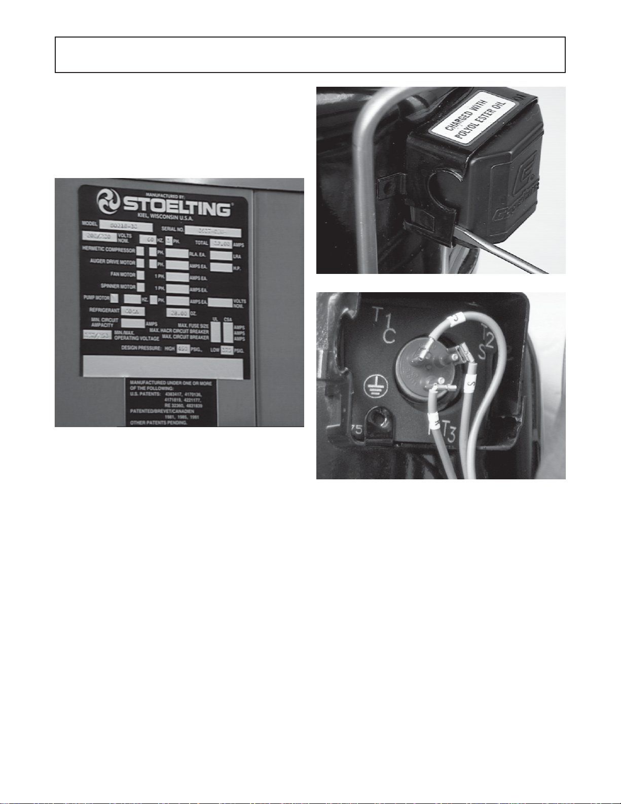
refrigerant. The proper charges are indicated on the nameplate. Figure 10.
Figure 11. Compressor Terminal Cover Removal
Figure 10. Nameplate
5.2 COMPRESSOR
The compressor is designed specifically for use with
R404A.
A. Winding Test
T o test the compressor motor windings for possible
problems perform the following steps:
WARNING
DISCONNECT FREEZER FROM ELECTRICAL SUPPL Y
SOURCE BEFORE SERVICING.
1. Remove the retaining screws from the right side
panel and slide the side panel out and down.
2. Remove the compressor terminal cover by inserting a standard screw driver between the terminal
cover and retaining frame, pry out side then hold
with your hand while prying the other side then
remove cover. (Fig.11)
Figure 12. Compressor Connections
NOTE
The following values are for T ecumseh model
CS14K6E-PFV-235 with the compressor at or about
room temperature. For other models or brands consult the manufacturer's service data manual.
3. Connect ohmmeter to terminal C and R. Resistance through the run winding should be
1.10 ohms with the ohmmeter set at times one.
(Fig. 13)
13
Page 20
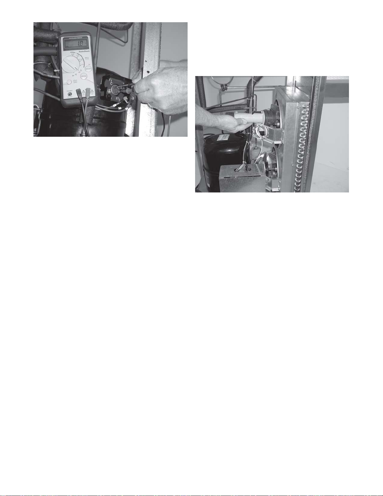
Figure 13. Ohm Meter Connection
4. Connect ohmmeter to terminal C and S. Resistance through the start winding should be 5.94
ohms with the ohmmeter set at times one.
5. To check if windings are shorted to ground connect one ohmmeter lead to a bare metal part on
the compressor such as any copper line leading
to or from the compressor and checking terminals
C, R, and S.
NOTE
The compressor is equipped with an internal overload protector. If the compressor trips the overload
check for high amperage draw.
2. Remove the retaining screws from the the right
side and back panel and slide the panels out
and down.
3. Visually inspect the condenser for dirt by shining
a light through the coil from the back (inside) of the
condenser. Figure 14.
Figure 14. Condenser
4. If the condenser is dirty, place a wet towel over the
front (outside) of the condenser.
5. Using compressed air or CO2 tank, blow out the
dirt from the back (inside) of the condenser. Most
of the dirt will cling to the wet towel.
5.3 CONDENSER
The air cooled condenser is a copper tube and aluminum
fin type. Condensing is totally dependent on air flow. A
plugged condenser or restrictions in the louvered grill will
restrict air flow. This will lower the capacity of the system
and damage the compressor.
The condenser must be kept clean from dirt and grease.
The freezer must have a minimum clearance of 6" at the
left and right side of the unit for free flow of air. Make sure
the freezer is not pulling over 100° F. of air in from other
equipment in the area.
The condenser filter and condenser require periodic cleaning. To clean refer to the following procedures:
W ARNING
DISCONNECT FREEZER FROM ELECTRICAL
SOURCE BEFORE SERVICING.
1. Remove the condenser filter by pulling straight
out to the front. Then visually inspect for dirt. If the
filter is dirty, shake or brush excess dirt off the
filter and wash in warm soapy water. Once the
filter is clean rinse thoroughly in warm, clear water
and shake dry, taking care not to damage the
filter in any way.
An alternative method of cleaning the condenser is to use
a condenser brush and vacuum.
NOTE
If the condenser is not kept clean, loss of refrigeration efficiency will result, causing extended run time
or soft product consistency .
5.4 EVAPORATOR
An TXV (thermostatic expansion valve) is used to meter the
refrigerant to the evaporator. The self regulating TXV is
preset at the factory for approximately 28 PSIG at 75°F
ambient temperature.
A. TXV Adjustments
To determine whether or not the TXV is in need of adjustment, perform the following procedure:
WARNING
DISCONNECT FREEZER FROM ELECTRICAL
SOURCE BEFORE SERVICING.
1. Remove the retaining screws from the bottom of
the left and right side panels and slide the panels
out and down.
14
Page 21
2. Remove the cap from the low side access port
and install a 0 - 100 PSIG gauge. Figure 15
Figure 15. Access Ports
3. Plug the freezer in, start the refrigeration cycle and
read the pressure.
7. Once the 28 PSIG reading is obtained, replace the
cap on the TXV, remove the pressure gauge and
replace the low side schrader valve cap.
B. TXV Removal
CAUTION
IF THE TXV IS REPLACED THE HEA T SINK (WET
CLOTH) MUST BE USED TO PREVENT DAMAGE
TO THE V AL VE.
WARNING
DISCONNECT FREEZER FROM ELECTRICAL
SOURCE OF SUPPL Y BEFORE SERVICING.
1. Assuming the left side, right side and back panels
are removed, perform the following procedures for
removing the TXV.
2. Remove the bulb from the suction line exiting from
the evaporator.
4. The proper gauge reading should be approximately 28 PSIG at 75°F. (21.1°C) Ambient temperature at the end of pull down. If the readings are
not within these parameters continue with the
following steps:
NOTE
Before performing the following procedures be absolutely certain it is necessary to adjust the TXV
and the freezer is full of cold mix.
5. Remove the cap on the TXV and using a service
wrench, turn the valve stem 1/4 (90°) turn counter
clockwise for more cooling or clockwise for less
cooling. Figure 16.
3. Recover refrigerant charge and leave a port open
to prevent pressure buildup during TXV removal.
4. Remove any insulation from the TXV and the
immediate surrounding lines.
5. Remove or push back any foam insulation from
surrounding lines.
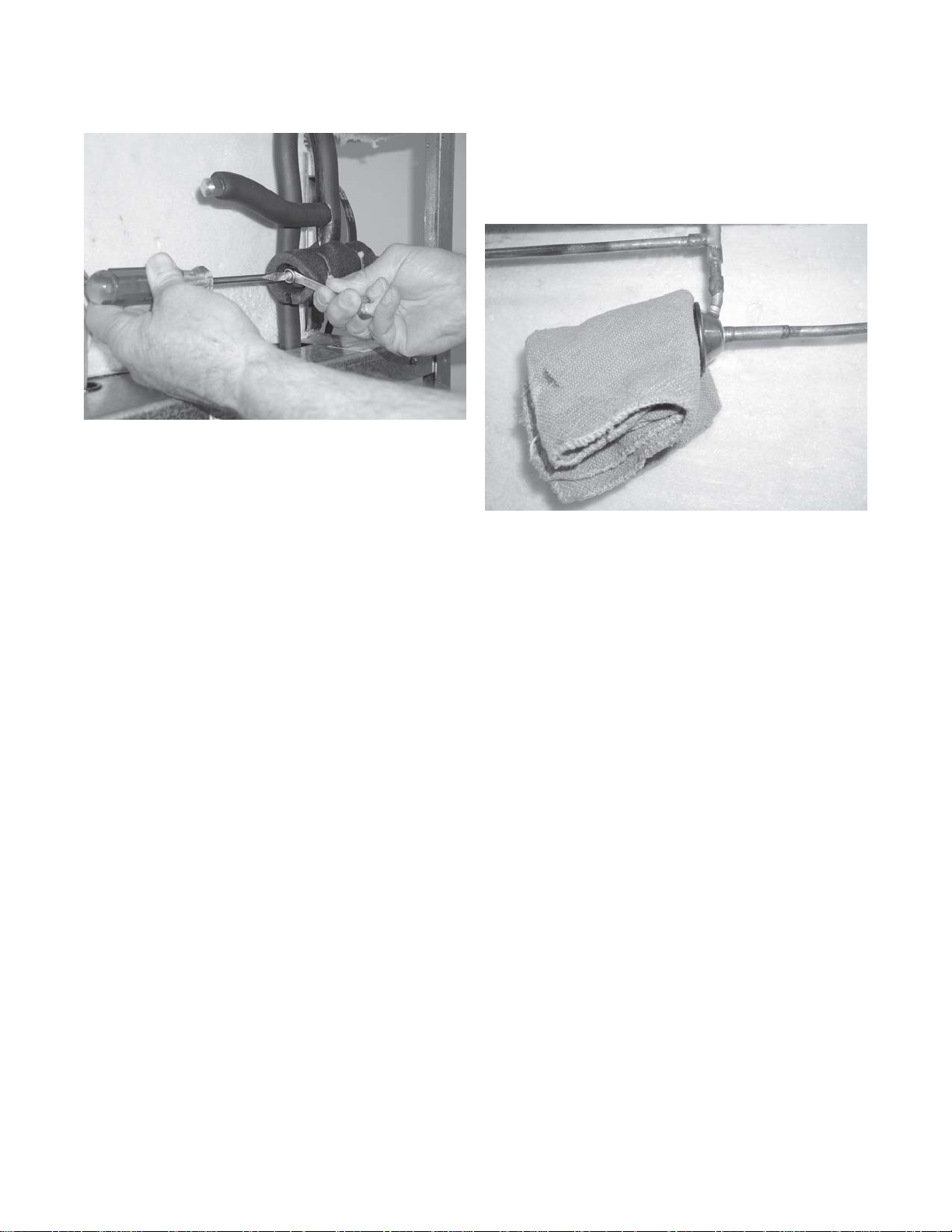
6. Apply a heat sink (wet cloth) to the valve dome.
Figure 17.
7. Unsweat the suction line and liquid line from the
TXV and remove the TXV with heat sink.
Figure 16. TXV
6. Should the readings not reach 28 PSIG repeat
step #7 until the correct reading is obtained.
Figure 17. Heat Sink
15
Page 22
C. TXV Replacement
To replace the TXV perform the following procedures:
CAUTION
WHEN REPLACING THE TXV A HEAT SINK (WET
CLOTH) MUST BE USED TO PREVENT DAMAGE
TO THE V AL VE.
1. Position the TXV with the heat sink so the liquid
and suction line correspond with the proper valve
ports. Figure 17.
2. With an open port braze the liquid line and suction
line to the TXV using the appropriate brazing
material.
3. Remove the heat sink from the TXV.
10.Triple evacuate the system. Evacuate twice to
1500 microns of mercury, break in the vacuum
each time with dry nitrogen. Then evacuate to 500
microns of mercury.
11.Recharge the system to nameplate specifications
and leak test.
5.5 HOPPER
A parallel refrigeration circuit feeds the hopper. A capillary
tube is used to meter the refrigerant to the hopper. An
E.P.R. valve (Evaporator Pressure Regulating) is used to
control the refrigerant at the outlet. The E.P.R. controls the
hopper pressure so, during heavy dispensing periods,
hopper temperatures will not drop and freeze the mix in the
hopper. The adjustable E.P.R. valve is preset at the
factory. If the hopper temperature is too cold or too warm,
an E.P.R. valve adjustment may be necessary.
4. Replace foam insulation to the surrounding lines.
5. Replace any insulation to the TXV and immediate
surrounding areas.
6. Install bulb on suction line exiting the evaporator.
NOTE
The TXV bulb should always be mounted on the top
of the horizontal line with the capillary end facing
the flow of refrigerant. Good contact between the
bulb and suction line is necessary for proper operation of the valve. The bulb must also be well insulated.
7. Purge and evacuate the system.
8. Break the vacuum to 0 PSIG with dry nitrogen,
then open an access port.
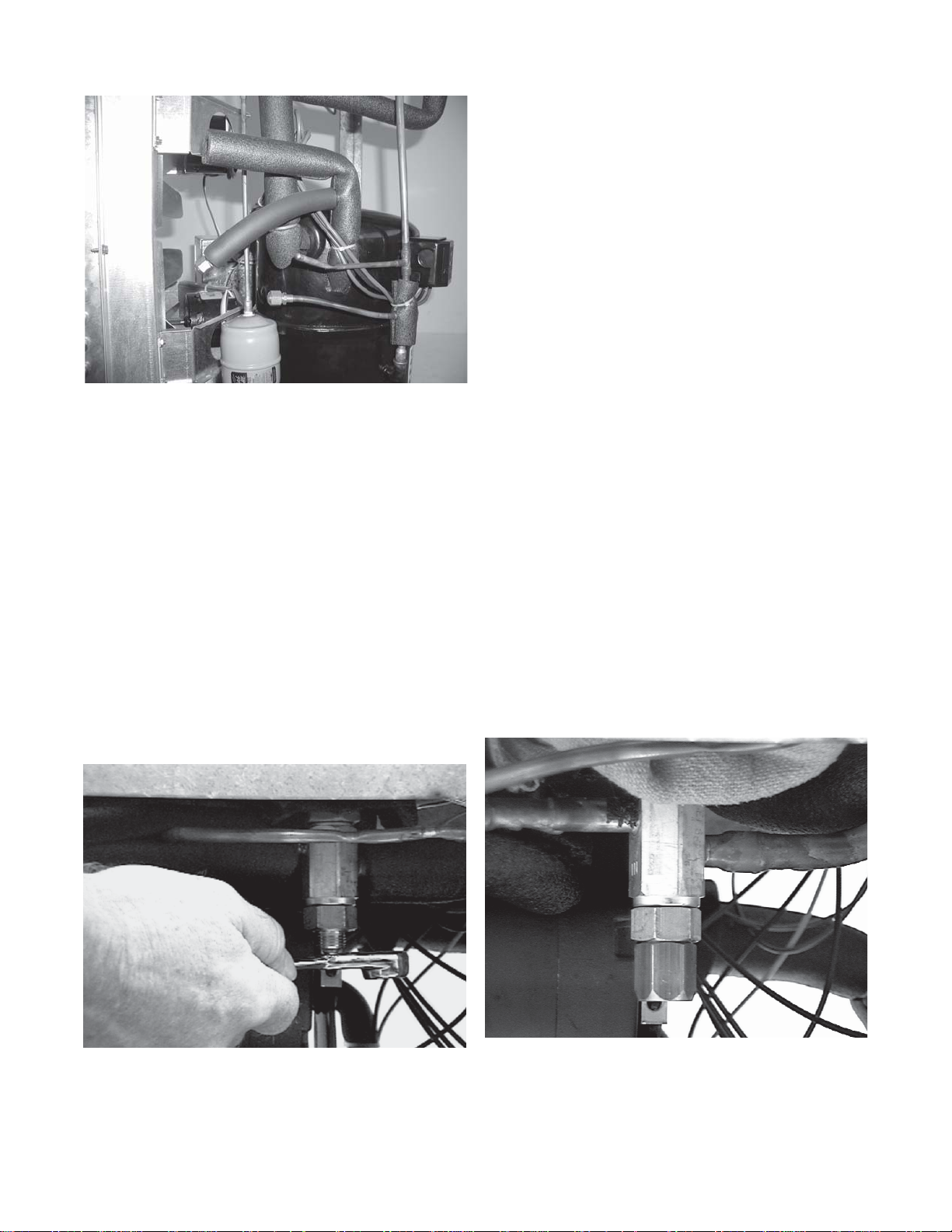
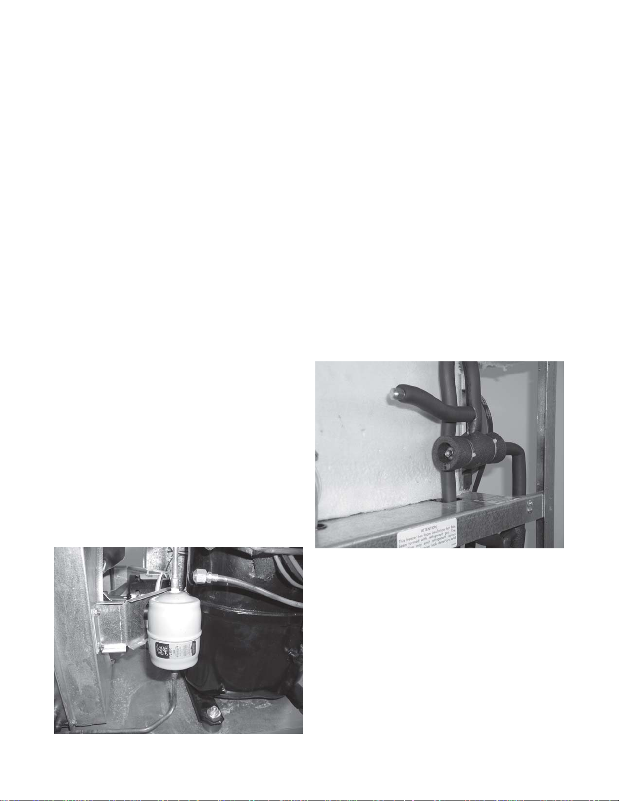
9. Remove the dryer by unsweating the refrigeration
lines then with an open port sweat in the replacement dryer. Make certain the arrow points in the
direction of flow. Figure 18.
A. E.P.R. Valve Adjustment
To adjust the E.P.R. valve, refer to the following procedures:
1. Remove the phillips head screws from the bottom
of the right side panel and remove the side panel
by sliding out and down.
2. Remove the cap from the E.P.R. access port.
Figure 19.
Figure 18. Drier
Figure 19. EPR and Access Port
3. Install a 0-100 P.S.I.G. gauge onto the E.P.R.
access port.
4. Start the refrigeration cycle and read the pressure.
NOTE
The ideal E.P .R. valve setting (69-71 PSIG) will not allow
mix to freeze to the walls of the hopper.
5. If the pressure gauge reading does not fall
between 69-71 PSIG parameters, proceed with
the following steps:
16
Page 23
6. Loosen the lock nut on the E.P .R. valve and
using a small screwdriver , turn the valve stem
1/4 (90°) turn counter clockwise for more cool
ing or clockwise for less cooling.Figure 20.
Figure 20. EPR Valve Adjustment
7. Allow the system to level out for 3 - 5 minutes
before taking another pressure reading.
2. Recover refrigerant charge and leave the port
open to prevent pressure build-up during
E.P .R. valve removal.
3. Remove foam rubber insulation from the surrounding lines.
4. Apply a heat sink (wet cloth) to the E.P.R.
valve. Figure 21.
8. Should the reading still not fall between 69-71
PSIG, repeat steps 6 and 7 until the correct
reading is obtained.
9. Once the 69-71 PSIG reading is obtained,
tighten the locknut snugly , remove the pressure
gauge and replace the E.P .R. access valve
cap.
10.Replace the side panel.
B. E.P.R. Removal
CAUTION
IF THE E.P.R. VALVE IS REPLACED THE HEA T
SINK (WET CLOTH) MUST BE USED TO PREVENT DAMAGE TO THE VA L VE.
1. Assuming the right side and back panelsare
removed, perform the following procedures for
removing the E.P .R. valve.
W ARNING
DISCONNECT THE FREEZER FROM ELECTRICAL SUPPL Y SOURCE BEFORE SERVICING.
Figure 21. EPR Heat Sink
5. Unsweat the hopper evaporator line and the line
leading to the low side of the main system from
the E.P.R. valve.
6. Remove the E.P .R. valve with the heat sink.
C. E.P.R. Replacement
CAUTION
IF THE E.P.R. VALVE IS REPLACED THE HEAT
SINK (WET CLOTH) MUST BE USED TO PREVENT DAMAGE TO THE V AL VE.
1. Position the E.P .R. valve with the heat sink, so
the hopper evaporator outlet line and the line
leading to the low side of the main system
correspond with the proper ports.
2. With an open port braze the lines to the E.P .R.
valve using the appropriate brazing material.
3. Remove the heat sink from the E.P .R. valve.
4. Replace any foam insulation to the surrounding
lines.
5. Purge and evacuate the system.
17
Page 24

6. Break the vacuum to 0 PSIG with dry nitrogen,
then open an access port.
7. Remove the dryer by unsweating the refrigeration
lines then with an open port sweat in the replacement dryer. Make certain the arrow points in the
direction of flow. Figure 22.
Figure 22. Filter Drier
Figure 23. Drier Cap. Tube Assembly
NOTE
Before unsweating the capillary tube at the hopper inlet it will be necessary to remove the foam insulation
from the capillary tube at that connection.
4. Remove the capillary tube dryer assembly.
B. Capillary Tube Replacement
8. Triple evacuate the system, evacuate twice to
1500 microns of mercury, break in the vacuum
each time with dry nitrogen, then evacuate to 500
microns of mercury.
9. Recharge the system to the nameplate specifications and leak test.
5.6 CAPILLARY TUBE
Capillary tube replacement may be necessary if the
correct hopper cooling cannot be obtained.
A. Capillary Tube Removal
W ARNING
DISCONNECT FREEZER FROM ELECTRICAL SUPPL Y SOURCE BEFORE SERVICING.
1. Remove the retaining screws from the right side
panel and pull the side panel out and down.
2. Recover refrigerant charge and leave a port open
to prevent pressure build-up during capillary tube
dryer assembly removal.
3. Unsweat capillary tube dryer assembly at the
dryer inlet and at the hopper inlet located at the
side of the hopper. Figure 23.
1. Position the capillary tube dryer assembly so
the large diameter tube is in position to be
brazed first using the appropriate brazing material.
2. Position the smaller diameter tube at the side
of the hopper and braze the tube to the hopper
inlet using the appropriate brazing material.
3. Replace the foam insulation to the hopper inlet
connections.
4. Purge and evacuate the system.
5. Break the vacuum to 0 PSIG with dry nitrogen,
then open an access port.
6. Remove the dryer by unsweating the refrigeration lines then with an open port sweat in the
replacement dryer. Make sure the arrow points
in the direction of flow.
7. Triple evacuate the system. Evacuate twice to
1500 microns of mercury, break in the vacuum
each time with dry nitrogen. Then evacuate to
500 microns of mercury.
8. Recharge the system to nameplate specifications and leak test.
18
Page 25

SECTION 6
ELECTRICAL
6.1 ELECTRICAL
The control system operates from drive motor torque.
When the product in the barrel freezes it puts a greater
load on the drive motor. As the resistance builds up the
drive motor body begins to rotate in the opposite direction of the motor shaft overcoming spring tension. When
the motor has rotated far enough it contacts a microswitch
shutting off the compressor. After time has passed or
some product has been drawn the resistance in the barrel decreases and the spring pulls the motor back. The
micro switch then closes and the compressor starts.
There is a 10 second time delay on the compressor start
and stop. The drive motor runs continuously .
6.2 FRONT ELECTRICAL BOX
The front electrical box contains the CLEAN-OFF-SERVE
switch, pump OFF/ON switch (SO318 only), safety switch
and mix low light. The box also contains the drive contactor,
24 volt transformer, liquid level control, ON/OFF time
delay timer and auto fill time delay relay (SO318 only).
Figure 24.
ÉÉ
É
ÊÊ
Ê
ÊÊ
Figure 25. Switch Removal
5. Replace the electrical panel and secure with the
four retaining screws.
B. Indicator
ÉÉ
Figure 24. Electrical Panel
To replace electrical components perform the following
procedures:
A. Switches
1. Remove the decorative panel by loosening the
two screws at the bottom of the panel, then pull
out and down.
1. Remove the decorative panel by loosening the
two screws at the bottom of the panel, then pull
out and down.
2. Identify and disconnect the wires from the
indicator.
3. Squeeze the four plastic retainers together and
push out through the hole. Figure 26.
4. Push the replacement through the hole and reconnect the wires.
ËË
Ë
ÌÌ
Ì
ÌÌ
ËË
2. Identify and disconnect the wires from the switch.
3. Remove the retaining nut and push out through
the hole. Figure 25.
4. Push the replacement switch through the hole
install and tighten the retaining nut, then
reconnect the wires.
19
ÊÊ
Ê
ÊÊ
Figure 26. Light Bulb Replacement
5. Replace the electrical panel and secure the two
retaining screws.
ÉÉ
É
ÉÉ
Page 26

C. Safety Switch
5. Reconnect the four wires.
1. Remove the two retaining screws from the switch
and lift out. Figure 27.
Figure 27. Safety Switch
2. Remove the two wires from the switch.
3. Connect the two wires to the replacement switch.
4. Locate and secure the replacement switch with
the two retaining screws.
D. Liquid Level Control (Low Mix Light)
1. Identify and remove the wires. Figure 28.
2. Remove the four retaining screws.
F. Drive Contactor
1. Identify and remove the wires.
2. Remove the two retaining screws and remove
the contactor.
3. Locate and secure the replacement contactor
with the two retaining screws.
4. Reconnect the wires.
G. Compressor ON/OFF Time Delay Relay
1. Identify and remove the wires.
2. Remove the retaining screw and remove the
relay.
3. Locate and secure the replacement relay with the
retaining screw.
4. Reconnect the two wires.
5. Adjust on and off times to 10 seconds.
WARNING
ALL REP AIRS MUST BE COMPLETED AND ALL
PANELS REPLACED BEFORE CONNECTING
THE FREEZER TO THE ELECTRICAL POWER.
THE REMAINING ELECTRICAL COMPONENTS
CAN BE REPLACED BY PERFORMING THE
FOLLOWING PROCEDURES:
Figure 28. Liquid Level Control
3. Remove the failed control.
4. Locate and secure the replacement control. Take
care to insure the wires are replaced properly or
the control will not work.
E. 24 Volt Transformer
1. Identify and remove the four wires.
2. Remove the two retaining screws, and remove
transformer.
H. Pump Time Delay Relay (SO318 only)
1. Release the two retainers by pushing to the side.
Figure 29.
Figure 29. Pump Relay
2. Unplug faulty relay.
3. Plug in replacement relay.
4. Push the two retainers onto the relay.
I. Torque Switch
3. Terminate the wires on the replacement transformer per the wiring diagram.
4. Locate and secure the replacement transformer
with the two retaining screws.
1. Remove the retaining screws from the right side
panel and slide out and down.
2. Identify and remove the wires and dummy
terminal from the switch.
20
Page 27

3. Remove the two retaining screws holding the
switch to the bracket. Fig. 30.
Figure 30. Torque Switch
4. Locate the replacement switch onto the bracket
and secure.
5. Connect the two wires and dummy terminal.
6.3 COMPRESSOR ELECTRICAL BOX
Remove the retaining screws from the right side panel
and pull the side panel out and down. Remove two
screws holding the electrical box cover and remove
cover.
A. Compressor Contactor
1. Identify and remove the wires. Fig. 31.
2. Remove the retaining screw and remove the
relay.
3. Locate and secure the replacement relay with
the two retaining screws.
4. Reconnect the wires.
C. Start and Run Capacitors
1. Identify and remove the wires.
2. Remove retaining bracket.
3. Install replacement capacitors and secure with
bracket.
4. Reconnect the wires.
WARNING
ALL REP AIRS MUST BE COMPLETED AND ALL
PANELS REPLACED BEFORE CONNECTING
THE FREEZER TO THE ELECTRICAL POWER.
THE REMAINING ELECTRICAL COMPONENTS
CAN BE REPLACED BY PERFORMING THE
FOLLOWING PROCEDURES:
6.4 MAJOR COMPONENT REPLACEMENT
Prepare for component removal. The procedures in this
section must be followed completely in the order in which
they appear. To remove any or all of the major components of the freezer, the following steps must be performed first.
Figure 31. Compressor Contactor
2. Remove the two retaining screws and remove
the contactor.
3. Locate and secure the replacement contactor
with the two retaining screws.
4. Reconnect the wires.
B. Relay
WARNING
DISCONNECT FREEZER FROM ELECTRICAL
SOURCE BEFORE SERVICING.
Remove the retaining screws from the side panels and
back panel, then remove panels.
A. Condenser Fan Motor Replacement
1. Identify the wires and disconnect. Fig. 32.
Ì
1. Identify and remove the wires.
Figure 32. Fan Motor
21
Page 28

2. Cut the necessary tie straps.
3. Remove the four retaining nuts and washers.
4. Remove the assembly from the freezer, and
remove the fan blade and fan bracket.
NOTE
Take a measurement of the fan blade position on
the shaft on the failed motor and position it in the
same place on the replacement motor shaft and
secure. Install the fan bracket onto the replacement
fan motor and secure.
5. Install the replacement condenser, and position
the condenser and shroud to align the holes.
Then secure with the 3/16" blind rivets or 3/16"
screws, nuts, and washers.
6. Braze the two refrigerant lines to the condenser
with an open access port to prevent pressure
build up.
7. Purge and evacuate the system.
8. Break the vacuum to 0 PSIG with dry nitrogen
then open an access port.
5. Locate the fan assembly into the freezer and
secure with the four retaining nuts and washers.
6. Properly terminate and reconnect all wires
and secure the wires with plastic tie straps.
B. Condenser Replacement
1. Recover the refrigerant charge and leave a port
open to prevent pressure build-up during condenser replacement.
2. Unsweat the two refrigerant lines. Then cover
exposed refrigerant lines to protect them from
debris while preparing the condenser for
removal.
3. To remove the condenser drill out the blind rivets
holding the condenser assembly to the frame.
Figure 33. Rivets can be accessed by removing
the lower front sheet metal . In addition to the
sheet metal retaining screws there are two acorn
nuts under the drip tray.
9. Remove the dryer by unsweating the refrigeration lines then with an open port sweat in the
replacement dryer. Make certain the arrow points
in the direction of flow.
10.Triple evacuate the system. Evacuate twice to
1500 microns of mercury, break in the vacuum
each time with dry nitrogen. Then evacuate to
500 microns of mercury.
11.Recharge the system to nameplate specifications and leak test.
C. Compressor Replacement
1. Remove the compressor terminal cover by
inserting a screwdriver between the terminal cover
and retaining frame, and pry out side, then hold
with your hand while prying the other side, then
remove cover.
2. ldentify and remove the three wires. Figure 34.
Figure 33. Condenser
NOTE
When replacing the front sheet metal re-seal the
seams with R.T.V.
4. Remove the condenser.
Figure 34. Electrical Wires
3. Remove the four nuts, washers, and bolts holding the compressor to the frame. Figure 35.
22
Page 29

Figure 35. Compressor
12.Remove the cap plugs from the replacement
compressor and with an open port braze the
suction and discharge lines to the compressor.
13.Connect the black wire to the overload and the
white wire to the relay. Then install the cover and
retaining clip.
14.Purge and evacuate the system.
15.Break the vacuum to 0 PSIG with dry nitrogen,
and open an access port.
16.Remove the dryer by unsweating the refrigeration lines and then with an open port sweat in the
replacement dryer. Make certain the arrow points
in the direction of the flow.
4. Recover the refrigerant charge and leave a port
open to prevent pressure build-up during
compressor replacement.
5. Remove and/or protect insulation that may be
contacted by flame or extreme heat, then unsweat
the discharge and suction line.
6. Remove the compressor through the right side of
the freezer.
7. Remove the four rubber compressor mounts
from the failed compressor.
NOTE
Rubber mounts are not always furnished with replacement compressors.
8. Check the compressor for a burn out condition
using an acid test kit. If acid is found, clean out the
system per the compressor manufacturers instructions.
9. Plug all open ports of the failed compressor.
17.Triple evacuate the system. Evacuate twice to
1500 microns of mercury, break in the vacuum
each time with dry nitrogen. Then evacuate to
500 microns of mercury.
18.Recharge the system to nameplate specifications.
19.Leak test and replace insulation.
D. Drive Motor Replacement
1. Remove the cover plate then identify and remove
the four wires.
2. Disconnect the ground wire.
3. Disconnect the torque spring by removing the nut
on the motor bracket and sliding off. Figure 36.
NOTE
A compressor returned to the company with any
open ports will void the warranty. Always plug any
open ports on a compressor that has been removed.
10.Install the four rubber mounts on the replacement compressor.
11.Install the replacement compressor into the
freezer and secure with the four bolts, washers
and nuts.
Figure 36. Torque Spring
4. Remove the two cap screws from the torque
switch bracket and move the bracket to the side.
Figure 37.
23
Page 30

Figure 37. Torque Switch Bracket
14.Locate torque switch bracket and secure with the
two screws.
15.Connect the electrical wires. Do not overlook the
ground wire, it must be connected.
If the belt tensioner needs adjustment perform the following procedures:
a. With idler loosely snug against mounting bracket,
rotate idler until belt is contacted.
b. With a wrench on large idler nut, rotate idler into
belt until indicator mark (single mark on idler half
against mounting bracket) aligns with first mark
closest to indicator mark (3 - 4.5 lbs. of tension).
5. Pull back belt tensioner and remove belt.
Figure 38.
Figure 38. Belt Tensioner
6. Remove the four retaining bolts, nuts and washers.
7. Slide the motor out through the back.
c. Tighten cap screw to lock idler into position.
E. Bearing Assembly Replacement
1. Remove the agitator assembly from the barrel.
2. Pull back the belt tensioner and remove the belt.
3. Measure the position of the pulley hub, then
remove by removing the three cap bolts and
turning two of the bolts in the threaded holes to
separate the hub from the pulley.
4. Remove the four retaining bolts and washers,
then remove the bearing and pulley assembly
through the back of the freezer. Figure 39.
8. Measure the position of the pulley before
removing.
9. Remove the pulley and bracket, then install on
the replacement motor in the same position.
10.Locate the replacement motor in the freezer with
the rubber pads in place over the mounting holes.
11.Secure the motor with the four bolts, nuts, and
washers.
12.Pull back the belt tensioner and install belt. Check
for proper alignment.
13.lnstall torque spring onto bracket and replace
nut.
Figure 39. Bearing Assembly
5. Install the bearing assembly on the barrel and
secure with the four retaining bolts and washers.
Pull back the belt tensioner and install the belt.
Check for proper alignment.
6. Locate the pulley on the replacement part and
securely tighten the three bolts.
24
Page 31

F. Axial Fan Replacement
1. Disconnect the two wires.
2. Remove the two 3/16" mounting screws, nuts and
washers.
3. Remove right side fan bracket, then remove fan
from right side. Figure 39.
4. Locate replacement motor in freezer.
5. Mount right side bracket to frame and motor, then
secure left side bracket to motor and tighten all
bolts, screws, nuts and washers.
6. Reconnect the two wires.
25
Page 32

26
Page 33

SECTION 7
TROUBLESHOOTING
:MELBORP ESUAC NOITCERROC
.spirtdaolrevorotomevirD
nehwnwodstuhsrezeerF(
)gninnur
.egatlovwoLylppusrewopkcehC
.yltcerrocnisesnepsidtcudorPniximwolrorednilyctcudorpn
.nihtootsitcudorPNAELCroFFOnihctiwselggoT
etatoRtoNseoDrotatigA.ffodeppirtdao
iximoN
.reppoh
.noitisop
.)C°7.73(
.gnidaerxirBreporpmI gnidaerxirBsahtahttcudorphtiwllifeR
.rotatigamorfgnissimedalbreparcS.edalbreparcsecalpeR
.nwa
rdrevogniebsirezeerF.wardfoetarnwodwolS
F°001tuobasierutarepmettneibmA
ogniebsirezeerF.wardfoetarehtnwodwolS
.ytridsiresnednoC.resnednocnaelC
lrevorotomevirD citamotuawolla,setunim5roffforezeerfnruT
.nwardrev
.nezorfrokcutsrotatigA .nezorffirezeerfni
.31dna11neewteb
.llufreppohdnarednilyctcudorppeeK
nihctiwselggotecalP
.teser
tcudorpwahT
.noitisopEVRES
.rezeerfmorfyawariatohtceridroevoM
.rotomevirdotrewopoN evirdnisehctiwsdnassenraheriwkcehC
.ecalperroriaperdnatiucric
sirotomevirD .yrassecenfiecalperdnakcehC
laitinInoslatsyrCecIoN
nwoDezeerF
.kcutSrognikaeLtogipS.gnissimroevitcefedsgnir"O"togipS evomeR.leveltogipswolebotximniarD
olB
.rezeerfot
.hcirootxiM deximylreporphtiwlliF.gnidaer"xirB"eka
.evitcefed
rewoptupnionrognidliubniesufnw
T
.rezeerfotwolfriadetcirtseR ehttuosegrahcsiddnatnorfehtnisretneriA
.tcudorpanihtootroftesycnetsisnoC .tcudorprekcihtaot
.ylbmessatogipsniximdeirD evomeR.leveltogipswo
otrewoptupniroesufnwolbrofkcehC
.rezeerf
.tcudorp
am,kcab
.wolfria
ycnetsisnocteS
.llatsnidnaetacirbul
lebotximniarD
tiwlliF.llatsnidnaelbmessa
.raelcerasaerahtobniatrecek
edisotedisdahsledomreilraewefA:ETON
,
dedeensasgnir"O"ecalper,naelc,togips
dnaelbmessasiD.togipsdnareniatertogips
-er,etacirbuL.hsurbdnaretawtohhtiwnaelc
.ximdiuqilh
27
Page 34

28
Page 35

SECTION 8
REPLACEMENT PARTS INFORMATION
8.1 ORDERING PARTS
To assure receipt of the proper replacement parts, supply your dealer or distributor with the following information:
A. MODEL NUMBER of equipment.
B. SERIAL NUMBER of model (stamped on nameplate).
DECALS AND TAGS
PART NUMBER DESCRIPTION
324105 DECAL - CAUTION: ELECT. SHOCK
324107 DECAL - CAUTION MOVING P ARTS
324141 DECAL - CAUTION: ROT A TING BLADES
324798 DECAL - CLEAN-OFF-SERVE SWITCH
324208 DECAL - REFRIG. LEAK CHECK
324393 DECAL - ST OEL TING SWIRL LOGO
324509 DECAL - CLEANING (SS & SHAKE)
324566 DECAL - WIRED ACCORDING TO . . .
324686 DECAL - DANGER ST ARTS AUT OMA TICALL Y
324689 DECAL - REAR SEAL ASSEMBLY
324799 DECAL - PUMP ON/OFF
324801 DECAL - MIX LOW
324825 DECAL - HEADER
C. PART NUMBER, PART NAME, AND QUANTITY
NEEDED. Many part names and numbers are listed
on drawings included in this manual.
NOTE
Minimum billing is $50.00.
D. WIRING DIAGRAMS reflect changes in effect with
the Serial Number which are also indicated by a
suffix.
29
Page 36

30
Page 37

SECTION 9
REFERENCE DRAWINGS
See Next Page.
31
Page 38

3233343536
Page 39

Page 40

Page 41

Page 42

Page 43

-SV
284104
37
-DS
Page 44

38
Page 45

-SV
-SV
39
Page 46

40
Page 47

744142
41
Page 48

42
Page 49

284104
-SV
-SV
43
Page 50

44
Page 51

SECTION 10
ACCESSORIES
Fill-O-Matic II
The Fill-O-Matic II is a self contained auto-fill system designed to be used with the Model SO318
and DQSO318 Freezer. The pump is built onto the cover of a 10 gallon mix vat. A draw tube
extends to the bottom of the container to supply the pump with mix, the mix then passes thru a
screen, thru the pump and discharges thru a hose to the freezer. The pump is controlled by a
pressure switch. The pump starts at 45 PSI and stops at 60 PSI.
Cleaning
1. Empty mix container completely.
2. Pour 2 gallons of quite warm detergent water into the mix container and pump thru the pump
and hoses.
NOTE
Do not allow the pump to run dry for more than a few minutes to prevent damage to the
pumps components.
3. Remove the strainer by turning counter clockwise, then thoroughly clean.
4. Apply a film of petro-gel to the male threads and "o" ring before reassembly. Do not over
tighten.
Sanitizing
1. Use a sanitizer mixed according to manufacturers instructions to provide a 100 parts per
million strength solution. Mix sanitizer in quantities of no less than 2 gallons (7.5 liters) of
120° water. Allow the sanitizer to contact the surfaces to be sanitized for 5 minutes. Any
sanitizer must be used only in accordance with the manufacturers instructions.
2. Pour the sanitizer into the mix container and pump thru the pump and hoses.
3. Make sure all the sanitizer has been pumped out and the container is completely empty,
then fill with mix and start the pump pushing out any sanitizer that may be remaining in the
hoses. The freezer barrel and hopper can now be filled.
45
Page 52

On/Off
Switch
Ç
115 Volt
15 Amp Plug
È
Strainer
Å
Fill-o-matic II
46
Page 53

474849
Page 54

Page 55

Fill-O-Matic III
The Fill-O-Matic III is a gas powered auto-fill system designed to be used with Slush and Cocktail
Freezers. The pump is built to hang on the side of a 10 gallon mix vat. The pump can be driven
by
either regulated CO2, nitrogen or filtered compressed air. A draw tube extends to the bottom of
the container to supply the pump with mix, the mix then passes thru the pump and discharges thru
a hose to the freezer. The pump is controlled by pressure in the mix line verses gas pressure to
the pump. Set the gas pressure to the pump between 20 to 40 PSIG.
Cleaning
1. Empty mix container completely.
2. Pour 2 gallons of quite warm detergent water into the mix container and pump thru the pump
and hoses.
NOTE
Do not allow the pump to run dry for more than a few minutes to prevent damage to the
pumps components.
Sanitizing
1. Use a sanitizer mixed according to manufacturers instructions to provide a 100 parts per
million strength solution. Mix sanitizer in quantities of no less than 2 gallons (7.5 liters) of
120° water. Allow the sanitizer to contact the surfaces to be sanitized for 5 minutes. Any
sanitizer must be used only in accordance with the manufacturers instructions.
2. Pour the sanitizer into the mix container and pump thru the pump and hoses.
3. Make sure all the sanitizer has been pumped out and the container is completely empty,
then fill with mix and start the pump pushing out any sanitizer that may be remaining in the
hoses. The freezer barrel and hopper can now be filled.
Page 56

Mix Outlet
Ë
Gas Inlet
Ë
É
Mix
Inlet
Ë
Gas
Outlet
Fill-o-matic III
50
Page 57

515253
Page 58

Page 59

SECTION 11
ADDENDUM
Dispenser Specifications
Electrical Refrigeration Crated Dimensions Dimensions
208/230/60/1 HFC-404A environmentally- Width: 22" (55.9cm) Width: 17.6"(44.7cm)
20amp circuit & plug friendly refrigerant Depth: 30" (76.2cm) Depth: 26.1"(66cm)
12 running amps 2 HP (14,800 BTUH) high- Height: 66" (167.7cm) Height: 61.2"(155cm) w/casters
1/2 HP Drive Motor efficiency compressor Weight: 400lbs.(182kg) Weight: 350lbs.(159kg)
Air cooled or Water cooled.
Page 60

54DS55565758596061626364656667
Page 61

Page 62

Page 63

Page 64

Page 65

Page 66

Page 67

Page 68

Page 69

Page 70

Page 71

Page 72

Page 73

Page 74

68
 Loading...