

Page 1

Model SO218B
OPERATORS MANUAL
Manual No. 513679 Rev.1
Page 2

Page 3

This manual provides basic information about the machine. Instructions and suggestions are
given covering its operation and care.
The illustrations and specifi cations are not binding in detail. We reserve the right to make
changes to the machine without notice, and without incurring any obligation to modify or provide new parts for machines built prior to date of change.
DO NOT ATTEMPT to operate the machine until instructions and safety precautions in this
manual are read completely and are thoroughly understood. If problems develop or questions
arise in connection with installation, operation, or servicing of the machine, contact Stoelting.
stoeltingfoodservice.com
Stoelting Foodservice Equipment
502 Highway 67
Kiel, WI 53042-1600
U.S.A.
Main Tel: 800.558.5807
Fax: 920.894.7029
Customer Service: 888.429.5920
Fax: 800.545.0662
Email: foodservice@stoelting.com
© 2014 PW Stoelting, LLC
Page 4

A Few Words About Safety
Safety Information
Read and understand the entire manual before
operating or maintaining Stoelting equipment.
This manual provides the operator with information
for the safe operation and maintenance of Stoelting
equipment. As with any machine, there are hazards
associated with their operation. For this reason safety
is emphasized throughout the manual. To highlight
specifi c safety information, the following safety defi ni-
tions are provided to assist the reader.
The purpose of safety symbols is to attract your attention to possible dangers. The safety symbols, and
their explanations, deserve your careful attention
and understanding. The safety warnings do not by
themselves eliminate any danger. The instructions
or warnings they give are not substitutes for proper
accident prevention measures.
If you need to replace a part, use genuine Stoelting
parts with the correct part number or an equivalent
part. We strongly recommend that you do not use
replacement parts of inferior quality.
Safety Alert Symbol:
This symbol Indicates danger, warning or caution.
Attention is required in order to avoid serious personal injury. The message that follows the symbol
contains important information about safety.
Signal Word:
Signal words are distinctive words used throughout
this manual that alert the reader to the existence and
relative degree of a hazard.
WARNING
The signal word “WARNING” indicates a potentially
hazardous situation, which, if not avoided, may result
in death or serious injury and equipment/property
damage.
CAUTION
The signal word “CAUTION” indicates a potentially
hazardous situation, which, if not avoided, may result
in minor or moderate injury and equipment/property
damage.
CAUTION
The signal word “CAUTION” not preceded by the
safety alert symbol indicates a potentially hazardous
situation, which, if not avoided, may result in equipment/property damage.
NOTE (or NOTICE)
The signal word “NOTICE” indicates information or
procedures that relate directly or indirectly to the
safety of personnel or equipment/property.
Page 5

TABLE OF
CONTENTS
Section Description Page
1 Description and Specifi cations
1.1 Description ..................................................................................................1
1.2 Specifi cations .............................................................................................2
2 Installation Instructions
2.1 Safety Precautions .....................................................................................5
2.2 Shipment and Transit ..................................................................................5
2.3 Machine Installation ....................................................................................5
3 Initial Set-Up and Operation
3.1 Operator’s Safety Precautions ....................................................................7
3.2 Operating Controls and Indicators ..............................................................7
3.3 Sanitizing ....................................................................................................8
3.4 Freeze Down and Operation ......................................................................9
3.5 Mix Information ...........................................................................................9
3.6 Removing Mix From Machine .....................................................................10
3.7 Cleaning the Machine .................................................................................10
3.8 Disassembly of Machine Parts ...................................................................10
3.9 Cleaning the Machine Parts .......................................................................11
3.10 Sanitize Machine and Machine Parts .........................................................11
3.11 Assembly of Machine .................................................................................11
3.12 Routine Cleaning ........................................................................................12
3.13 Preventative Maintenance ..........................................................................12
3.14 Extended Storage .......................................................................................15
4 Troubleshooting
4.1 Light Indicators ...........................................................................................17
4.2 Troubleshooting ..........................................................................................17
5 Replacement Parts
5.1 Decals and Lubrication ...............................................................................19
5.2 Auger Shaft and Faceplate Parts ...............................................................20
5.3 Hopper Parts ..............................................................................................22
5.4 Autofi ll Options ...........................................................................................23
Page 6

Page 7
SECTION 1
DESCRIPTION AND SPECIFICATIONS
1.1 DESCRIPTION
The Stoelting SO218B machine is gravity fed. It is equipped
with fully automatic controls to provide a uniform product.
It operates with almost any type frozen beverage mix. This
manual is designed to help qualifi ed service personnel and
operators with the installation, operation and maintenance
of the Stoelting SO218B gravity machine.
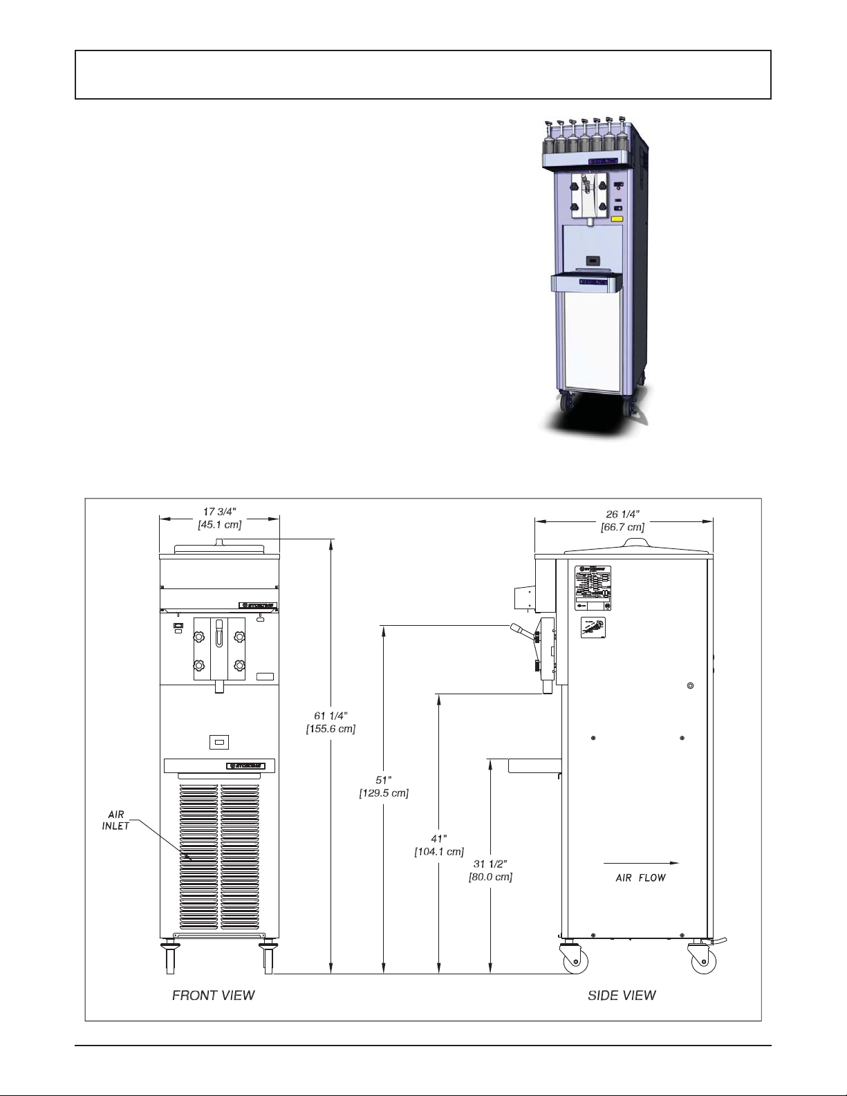
Figure 1-1 Model SO218B
Operators Manual #513679 Rev.1 1 SO218B Model Machine
Page 8

Model SO218B
Dimensions Machine with crate
width 17-1/2’’ (44,5 cm) 25’’ (63,5 cm)
height 64-1/2’’ (163,8 cm) 66’’ (167,6 cm)
depth 26-3/8’’ (67,0 cm) 51’’ (129,5 cm)
Weight 315 lbs (142,8 kg) 410 lbs (185,9 kg)
Electrical 1 Phase, 208-240 VAC, 60Hz
running amps 12A
connection type NEMA6-20P power cord provided
Compressor 14,000 Btu/hr
Drive Motor 1/2 hp
Air Flow Air cooled units require 3” (7,6 cm) air space at front and back.
Plumbing Fittings Water cooled units require 3/8” N.P.T. water and drain fi ttings.
Hopper Volume 7 gallon (26,50 liters)
Freezing Cylinder
Volume
2 gallon (7,57 liters)
Operators Manual #513679 Rev.1 2 SO218B Model Machine
Page 9

SECTION 2
INSTALLATION INSTRUCTIONS
2.1 SAFETY PRECAUTIONS
Do not attempt to operate the machine until the safety
precautions and operating instructions in this manual are
read completely and are thoroughly understood.
Take notice of all warning labels on the machine. The labels have been put there to help maintain a safe working
environment. The labels have been designed to withstand
washing and cleaning. All labels must remain legible for
the life of the machine. Labels should be checked periodically to be sure they can be recognized as warning labels.
If danger, warning or caution labels are needed, indicate
the part number, type of label, location of label, and quantity
required along with your address and mail to:
STOELTING
ATTENTION: Customer Service
502 Hwy. 67
Kiel, Wisconsin 53042
2.2 SHIPMENT AND TRANSIT
The machine has been assembled, operated and inspected
at the factory. Upon arrival at the fi nal destination, the
entire machine must be checked for any damage which
may have occurred during transit.
With the method of packaging used, the machine should
arrive in excellent condition. THE CARRIER IS RESPONSIBLE FOR ALL DAMAGE IN TRANSIT, WHETHER
VISIBLE OR CONCEALED. Do not pay the freight bill
until the machine has been checked for damage. Have
the carrier note any visible damage on the freight bill. If
concealed damage and/or shortage is found later, advise
the carrier within 10 days and request inspection. The
customer must place claim for damages and/or shortages
in shipment with the carrier. Stoelting, Inc. cannot make
any claims against the carrier.
2.3 MACHINE INSTALLATION
Installation of the machine involves moving the machine
close to its permanent location, removing all crating, setting in place, assembling parts, and cleaning.
A. Uncrate the machine.
B. Accurate leveling is necessary for correct drainage
of machine barrel and to ensure correct overrun.
Place a bubble level on top of the machine at each
corner to check for level condition. If adjustment
is necessary, level the machine by turning the
bottom part of each leg in or out.
C. Correct ventilation is required. The SO218B
requires 3” clearance at the front and back.
CAUTION
Failure to provide adequate ventilation will void
warranty.
D. Place the CLEAN-ON-OFF switch in the OFF
position.
WARNING
Do not alter or deform electrical plug in any way.
Altering the plug to fi t into an outlet of different con-
fi guration may cause fi re, risk of electrical shock,
product damage and will void warranty.
E. Connect the power cord to the proper power
supply . The plug is designed for 208-240VAC / 20
amp duty . Check the nameplate on your machine
for proper supply . The unit must be connected to a
properly grounded receptacle. The electrical cord
furnished as part of the machine has a three prong
grounding type plug. The use of an extension
cord is not recommended, if necessary use one
with a size 12 gauge or heavier with ground wire.
Do not use an adapter to get around grounding
requirement.
Operators Manual #513679 Rev.1 3 SO218B Model Machine
Page 10

Operators Manual #513679 Rev.1 4 SO218B Model Machine
Page 11

SECTION 3
INITIAL SET-UP AND OPERATION
3.1 OPERATOR’S SAFETY PRECAUTIONS
SAFE OPERATION IS NO ACCIDENT; observe these
rules:
A. Know the machine. Read and understand the
Operating Instructions.
B. Notice all warning labels on the machine.
C. Wear proper clothing. Avoid loose fi tting garments,
and remove watches, rings or jewelry that could
cause a serious accident.
D. Maintain a clean work area. Avoid accidents by
cleaning up the area and keeping it clean.
E. Stay alert at all times. Know which switch, push
button or control you are about to use and what
effect it is going to have.
F . Disconnect electrical cord for maintenance. Never
attempt to repair or perform maintenance on the
machine until the main electrical power has been
disconnected.
G. Do not operate under unsafe operating conditions.
Never operate the machine if unusual or excessive
noise or vibration occurs.
3.2 OPERATING CONTROLS AND INDICATORS
Before operating the machine, it is required that the operator know the function of each operating control. Refer
to Figure 3-1 for the location of the operating controls on
the machine.
WARNING
High voltage will shock, burn or cause death. The
OFF-ON switch must be placed in the OFF position
prior to disassembling for cleaning or servicing. Do
not operate machine with cabinet panels removed.
A. Spigot Switch
The spigot switch automatically starts the auger
drive and refrigeration systems when the spigot is
opened to dispense product. When the spigot is
closed, the drive motor and compressor remain on
until the product in the freezing cylinder reaches
the proper consistency..
B. CLEAN-OFF-ON Switch
The CLEAN-OFF-ON switch is used to supply
power to the control circuit. When the switch is in
the OFF (middle) position, power is not supplied
to the control board or refrigeration system. When
Diagnostic
Light
Add Mix
Indicator
Clean/Off/On
Switch
Figure 3-1 Controls
Operators Manual #513679 Rev.1 5 SO218B Model Machine
Page 12

the switch is in the ON position, the machine
operates in the freezing mode. When the switch
is in the CLEAN position, all refrigeration stops
and the auger starts rotating.
C. ADD MIX Light
The ADD MIX light fl ashes to alert the operator
to a low mix condition. It does so by monitoring
the mix level in the hopper. When the ADD MIX
light is fl ashing, refi ll hopper immediately.
NOTE
Failure to refi ll hopper immediately may result in
operational problems.
D. Diagnostic Light
The Diagnostic Light is on during defrost mode
and fl ashes if an error occurs. The light fl ashes
once if there is a compressor error. There are two
quick fl ashes if there is an auger error. And there
are three quick fl ashes if the machine is left in
clean mode for more than 20 minutes. Refer to
the troubleshooting section for details.
E. Front Door Safety Switch
The front door safety switch prevents the auger
from turning when the front door is removed. The
switch is open when the door is not in place and
closed when the door is properly installed.
3.3 SANITIZING
Sanitizing must be done after the machine is cleaned and
just before the hopper is fi lled with mix. Sanitizing the night
before is not effective. However , you should always clean
the machine and parts after each use.
The United States Department of Agriculture and
the Food and Drug Administration require that all
cleaning and sanitizing solutions used with food
processing equipment be certifi ed for this use.
When sanitizing the machine, refer to local sanitary regulations for applicable codes and recommended sanitizing
products and procedures. The frequency of sanitizing
must comply with local health regulations.
Mix sanitizer according to manufacturer’s instructions to
provide a 100 parts per million (ppm) strength solution and
check the solution with chlorine test strips. Mix sanitizer
in quantities of no less than 2 gallons (7.5 liters) of 90°
to 110°F (32° to 43°C) water. Allow sanitizer to contact
the surfaces to be sanitized for 5 minutes. Any sanitizer
must be used only in accordance with the manufacturer’s
instructions.
CAUTION
Do not allow sanitizer to remain in contact with
stainless steel parts for prolonged periods. Prolonged contact of sanitizer with machine may cause
corrosion of stainless steel parts.
In general, sanitizing may be conducted as follows:
A. Prepare Stera-Sheen Green Label Sanitizer
or equivalent according to manufacturer’s
instructions to provide a 100 ppm strength solution.
Mix the sanitizer in quantities of no less than
2 gallons of 90° to 110°F (32° to 43°C) water.
Check the strength of the sanitizing solution. Use
a chlorine test strip and color chart to make sure
the solution has 100 ppm. Any sanitizer must be
used only in accordance with the manufacturer’s
instructions.
B. Pour the sanitizing solution into the hopper and
place the switch in the CLEAN position. Check
for leaks.
C. Clean sides of hopper and underside of hopper
cover using a soft bristle brush dipped in the
sanitizing solution.
D. After fi ve minutes, place a bucket under the spigot
and open spigot to drain most sanitizing solution.
Leave a small amount of the sanitizing solution
in the freezing cylinder. Place the switch in the
OFF (middle) position.
E. Collect the remaining sanitizing solution in a cup
and test the chlorine contents with a new test strip.
A reading of 100 ppm or more is acceptable.
If the reading is less than 100 ppm, sanitize the
machine again.
If the reading is less than 100 ppm after sanitizing
the second time, disassemble and wash the
machine again.
3.4 FREEZE DOWN AND OPERATION
This section covers the recommended operating procedures for the safe operation of the machine.
A. Sanitize just prior to use.
B. Place the switch in the OFF (middle) position.
C. Fill the hopper with mix.
D. Open spigot and drain a small amount of mix to
remove any remaining sanitizer.
E. Place the switch in the ON position.
NOTE
After the drive motor starts, there is a delay before
the compressor starts.
F. After 8 to 12 minutes the product will be at
consistency and ready to serve. Freeze down
time may vary depending on the type of product
used and the starting product temperature.
G. To dispense, pull the spigot handle down to open
the spigot.
Operators Manual #513679 Rev.1 6 SO218B Model Machine
Page 13

H. The machine is designed to dispense the product
at a reasonable draw rate. If the machine is
overdrawn, the result is a soft product or a product
that does not dispense at all. If this occurs, allow
the machine to run for approximately 30 seconds
before dispensing additional product.
I. Do not operate the machine when the ADD MIX
light is on. Refi ll the hopper immediately.
3.5 DEFROST MODE
If the spigot has not been opened in 3 hours, defrost
mode begins. During defrost mode the drive motor runs
for 90 seconds every 7 minutes and the diagnostic light
remains lit.
End defrost mode by turning the CLEAN-OFF-ON switch
OFF then back ON or by opening the spigot.
3.5 MIX INFORMATION
Mix can vary considerably from one manufacturer to another. Dif ferences in the quantity and quality of ingredients
have a direct bearing on the fi nished frozen product. A
change in machine performance that cannot be explained
by a technical problem may be related to the mix.
Proper product serving temperature varies from one
manufacturer’s mix to another. Stackable slush mixes
generally provide satisfactory product from 24° to 28°F
(-4° to -2°C).
When checking the temperature, stir the thermometer in
the frozen product to obtain an accurate reading.
3.6 REMOVING MIX FROM MACHINE
To remove the mix from the machine, refer to the following steps:
A. Place the switch in the CLEAN position to rotate
the auger. Allow the mix to agitate in freezing
cylinder until the mix has become liquid, about 5
minutes.
B. Drain the liquid mix by opening the spigot. A
container should be placed under the spigot to
collect the liquid mix.
C. Place the switch in the OFF (middle) position.
B. Place the switch in the CLEAN position to rotate
the auger.
C. Allow the water to agitate for approximately 30
seconds.
D. Open the spigot to drain the water. Remember to
place a container under the spigot to catch the
water. When the water has drained, place the
switch in the OFF (middle) position. Allow the
freezing cylinder to drain completely.
E. Prepare sanitizing solution according to
manufacturer’s instructions to provide a 100 ppm
strength solution. Mix the sanitizer in quantities
of no less than 2 gallons of 90° to 110°F (32° to
43°C) water. Check the strength of the sanitizing
solution. Use a chlorine test strip and color chart
to make sure the solution has 100 ppm. Repeat
steps A through D using the sanitizing solution.
3.8 DISASSEMBLY OF MACHINE PARTS
Inspect for worn or broken parts each time the machine
is disassembled. Replace all worn or broken parts to
ensure safety to both the operator and the customer and
to maintain good machine performance and a quality
product. Frequency of cleaning must comply with the
local health regulations.
T o disassemble the machine, refer to the following steps:
CAUTION
Hazardous Moving Parts.
Revolving auger shaft can grab and cause injury.
Place the switch in the OFF (middle) position before
disassembling for cleaning or servicing.
A. Remove hopper cover.
B. Pull out the spigot pin by its ring.
3.7 CLEANING THE MACHINE
NOTE
The frequency of cleaning the machine and machine parts must comply with local health regulations.
After the mix has been removed from the machine, the
machine must be cleaned. To clean the machine, refer
to the following steps:
A. Close the spigot and fi ll the hopper with 2 gallons
(8 liters) of tap water.
Operators Manual #513679 Rev.1 7 SO218B Model Machine
Page 14

C. Remove the spigot handle.
D. Remove front door by turning the circular knobs
and then pulling door off the studs.
K. Remove o-rings (2) from the spigot by fi rst wiping
off the lubricant using a clean paper towel. Then
squeeze the o-ring upward with a dry cloth. When
a loop is formed, roll the o-ring out of the groove.
M. Remove rear seal and o-ring from auger.
N. Disassemble the rear seal assembly.
N. Remove drain tray, drip tray and drip tray grid.
E. Remove the auger assembly from the freezing
cylinder.
F. Remove o-ring from groove in front door.
H. Remove auger support bushing.
J. Remove spigot body from the front door.
3.9 CLEANING AND SANITIZING THE
MACHINE PARTS
Place all loose parts in a pan or container and take to
the wash sink for cleaning. Local and state health codes
dictate the procedure required. Some health codes require
a four-sink process (pre-wash, wash, rinse, sanitize, and
air-dry), while other codes require a three-sink process
(without the pre-wash step). The following procedures
are a general guideline only . Consult your local and state
health codes for procedures required in your location.
A. Prepare Stera-Sheen or equivalent cleaner in
2 gallons of 90° to 110°F (32° to 43°C) water
following manufacturers instructions.
B. Prepare sanitizing solution according to
manufacturer’s instructions to provide a 100 ppm
strength solution. Mix the sanitizer in quantities
of no less than 2 gallons of 90° to 110°F (32° to
43°C) water. Check the strength of the sanitizing
solution. Use a chlorine test strip and color chart
to make sure the solution has 100 ppm.
D. Place all parts in the cleaning solution and clean
the parts with the provided brushes. Rinse all
parts with clean 90° to 1 10°F (32° to 43°C) water.
Place the parts in the sanitizing solution.
E. Wash the hopper and freezing cylinder with the
90° to 1 10°F (32° to 43°C) cleaning solution and
brushes provided.
Operators Manual #513679 Rev.1 8 SO218B Model Machine
Page 15

Clean Rear
Seal Surface
F. Clean the rear seal surfaces from the inside of
the freezing cylinder with the 90° to 110°F (32°
to 43°C) cleaning solution.
3.10 SANITIZE MACHINE
A. Assemble all o-rings onto the parts dry, without
lubrication. Then apply a thin fi lm of sanitary
lubrication to the exposed surfaces of the o-rings.
Also apply a thin fi lm of sanitary lubricant to the
inside and outside of the front auger support
bushing.
CAUTION
Do not allow sanitizer to remain in contact with
stainless steel parts for prolonged periods. Prolonged contact of sanitizer with machine may cause
corrosion of stainless steel parts.
A. Use Stera-Sheen or equivalent sanitizing solution
mixed according to manufacturer’s instructions
to provide 100 parts per million strength solution.
Mix sanitizer in quantities of no less than 2 gallons
(7.5 liters) of 90° to 110°F (32° to 43°C) water.
Any sanitizer must be used only in accordance
with the manufacturer’s instructions.
B. With the large brush provided, sanitize the rear
of the freezing cylinder by dipping the brush in
the sanitizing solution and brushing the rear of
the cylinder.
3.11 ASSEMBLY OF MACHINE
T o assemble the machine parts, refer to the following steps:
NOTE
Petrol Gel sanitary lubricant or equivalent must be
used when lubrication of parts is specifi ed.
NOTE
The United States Department of Agriculture and
the Food and Drug Administration require that lubricants used on food processing equipment be certifi ed for this use. Use lubricants only in accordance
with the manufacturer’s instructions.
B. Assemble the rear seal adapter onto the auger
with the spring facing towards the front. Be sure
the o-ring is in place before installing the assembly.
C. Assemble the o-ring into the rear seal and
assemble the seal onto the auger. DO NOT
lubricate the rear seal o-ring.
Do Not
Lubricate
O-Ring
Operators Manual #513679 Rev.1 9 SO218B Model Machine
Page 16

D. Put a small amount of spline lubricant on the hex
end of the auger shaft. A small container of spline
lubricant is shipped with the machine.
D. Install the plastic auger blades onto the auger.
E. Push the auger into the freezing cylinder and
rotate it slowly until the auger engages the drive
shaft.
F. Insert the spigot body into the front door.
G. Install the support bushing onto the auger.
H. Install the front door onto the machine.
K. Insert the spigot handle so the hole lines up and
insert the spigot pin.
L. Install the hopper cover , drain tray, drip tray , and
drip tray grid.
The machine is assembled and ready to be sanitized.
3.12 CONSISTENCY ADJUSTMENT
The consistency adjustment screw is located behind the
right side panel near the back. Remove the black plug to
access the screw. To adjust consistency use a fl at head
screwdriver. Turn clockwise for thicker product and counterclockwise for thinner product. Allow 15-30 minutes for
the consistency change to show up in the product.
I. Install the knobs on the machine studs.
J. Look for the proper seal between the freezing
cylinder, o-ring, and front door.
Operators Manual #513679 Rev.1 10 SO218B Model Machine
3.13 ROUTINE CLEANING
T o remove spilled or dried mix from the machine exterior ,
wash in the direction of the fi nish with warm soapy water
and wipe dry. Do not use highly abrasive materials as
they mar the fi nish.
Page 17

3.14 PREVENTIVE MAINTENANCE
Stoelting recommends that a maintenance schedule be
followed to keep the machine clean and operating properly.
A. DAILY
1. The exterior should be kept clean at all times to
preserve the luster of the stainless steel. A mild
alkaline cleaner is recommended. Use a soft cloth
or sponge to apply the cleaner.
B. WEEKLY
1. Check o-rings and rear seal for excessive wear
and replace if necessary.
2. Remove the drip tray by gently lifting up to
disengage from the support and pulling out. Clean
behind the drip tray and front of the machine with
warm soapy water.
C. QUARTERLY
Air Cooled
The air-cooled condenser is a copper tube and aluminum
fi n type. Condensing is totally dependent upon airfl ow . A
plugged condenser fi lter, condenser , or restrictions in the
louvered panel restrict airfl ow. This lowers the capacity of
the system and damages the compressor.
The condenser must be kept clean of dirt and grease. The
machine must have 3” (7.6 cm) ventilation. Make sure the
machine is not pulling over 100° F (37° C) air from other
equipment in the area.
The condenser and condenser fi lter require periodic clean-
ing. To clean, refer to the following procedures.
NOTE
If the condenser is not kept clean, refrigeration effi ciency is lost.
Air Cooled Condenser Cleaning
A. Slide the condenser fi lter out of the holding
bracket. Visually inspect it for dirt. If the fi lter is
dirty , shake or brush excess dirt of f the fi lter and
wash it in warm, soapy water. Once the fi lter is
clean rinse thoroughly in warm, clear water and
shake dry , taking care not to damage the fi lter in
any way.
C. Visually inspect the condenser for dirt by shining
a light through the coil from the back (inside) of
the condenser.
D. If the condenser is dirty, place a wet towel over
the front (outside) of the condenser.
E. Using a vacuum, carefully clean the condenser
coil from the inside and outside of the machine.
A stif f bristled brush may help in releasing debris
from between the condenser coils.
Water Cooled
The water-cooled condenser is a tube and shell type. The
condenser needs a cool, clean supply of water to properly
cool the machine. Inlet and discharge lines must be 3/8”
I.D. minimum. Make sure the machine is receiving an
unrestricted supply of cold, clean water.
E. SEMI-ANNUALLY
1. Disconnect the machine from the power source.
2. Lubricate the condenser fan motor with S.A.E.
20 weight oil. Three to six drops are required.
3.15 EXTENDED STORAGE
Refer to the following steps for storage of the machine
over any long period of shutdown time:
A. Place the CLEAN-OFF-ON switch in the OFF
(middle) position.
B. Disconnect (unplug) from the electrical supply
source.
C. Clean all parts that come in contact with mix
thoroughly with a warm water cleaning solution
Rinse in clean water and dry parts. Do not sanitize.
NOTE
Do not let the cleaning solution stand in the hopper or in the freezing cylinder during the shutdown
period.
D. Remove, disassemble and clean the front door
and auger parts.
E. In a water cooled machine, disconnect the water
lines and drain water. With a fl athead screwdriver,
hold the water valve open and use compressed
air to clear the lines of any remaining water.
Operators Manual #513679 Rev.1 11 SO218B Model Machine
Page 18

Operators Manual #513679 Rev.1 12 SO218B Model Machine
Page 19

SECTION 4
TROUBLESHOOTING
4.1 LIGHT INDICATORS
The machine has two lights that alert the user if a problem occurs: an ADD MIX light and a Diagnostic Light.
The ADD MIX light fl ashes to alert the operator to a low mix condition. It does so by monitoring the mix level in the
hopper. When the ADD MIX light is fl ashing, refi ll hopper immediately.
The Diagnostic Light fl ashes if an error occurs. Refer to the chart below for details.
Indication On One Blink Two Blinks Three Blinks
Conditions Defrost Mode
Self
Correction
Operation
Corrective
Action
N/A N/A
Every 7 minutes
the auger runs
for 90 seconds.
End Defrost
Mode by turning
Clean/Off/On
switch OFF then
turning it back
ON. Opening
the spigot also
ends Defrost
Mode.
Torque is not
met after 20
minutes
Timers or until
torque switch
remains closed
for 3 seconds.
Contact Service
Technician
Drive current is not sensed
The machine attempts to sense drive
current with a 3 second pre-stir. If current
is sensed, the machine returns to normal
operation. If current is not sensed, the
machine waits 7 minutes and tries to
sense current with another 3 second
pre-stir. After the third attempt, the
compressor runs on timers.
Timers Off
Contact Service Technician
Machine left in clean
mode for over 20
minutes
N/A
Turn CLEAN-OFF-
ON switch to OFF
(middle) position then
turn the switch to ON.
4.2 TROUBLESHOOTING
PROBLEM POSSIBLE CAUSE REMEDY
1 Power to machine is off. 1 Supply power to machine.
Machine does not
run.
Machine will not
shut off.
Product is too fi rm.
Operators Manual #513679 13 SO218B Model Machine
2 Blown fuse or tripped circuit. 2 Replace or reset.
3 Freeze-up (auger will not turn). 3 Turn Clean/Off/On switch Off for 15 minutes,
then restart.
4 Front door not in place. 4 Assemble front door in place.
1 Drive belt failure. 1 Replace drive belt.
2 Consistency temperature setting is too
fi rm.
3 Refrigeration problem. 3 Check system. (Call distributor for service)
1 Consistency temperature setting is too
fi rm.
2 Turn Consistency Adjustment screw counter-
clockwise.
1 Turn Consistency Adjustment knob counter-
clockwise.
Page 20

4.2 TROUBLESHOOTING - CONTINUED
PROBLEM POSSIBLE CAUSE REMEDY
Product is too thin.
Product does not
dispense.
Drive belt slipping
or squealing.
Rear auger seal
leaks.
Front door leaks.
1 No vent space for free fl ow of cooling
air.
2 Condenser is dirty. 2 Clean. (See Section 3)
3 Consistency setting too soft. 3 Turn Consistency Adjustment knob clockwise.
4 Auger is assembled incorrectly. 4 Remove mix, clean, reassemble, sanitize and
5 Refrigeration problem. 5 Check system. (Call distributor for service)
1 No mix in hopper. 1 Fill hopper with mix
2 Drive motor overload tripped. 2 Wait for automatic reset. (If condition
3 Drive belt failure. 3 Replace drive belt.
4 Freeze-up (Auger will not turn). 4 Turn Clean/Off/On switch Off for 15 minutes,
1 Worn drive belt. 1 Replace drive belt.
2 Freeze-up (Auger will not turn). 2 Turn Clean/Off/On switch Off for 15 minutes,
3 Not tensioned properly. 3 Adjust belt tension
1 Outside surface of rear auger seal is
lubricated.
2 Rear seal missing or damaged. 2 Check or replace.
3 Seal o-ring missing, damaged or
installed incorrectly.
4 Worn or scratched auger shaft. 4 Replace auger shaft.
1 Front door knobs are loose. 1 Tighten knobs.
2 Spigot parts are not lubricated. 2 Remove spigot and lubricate o-rings.
3 Chipped or worn spigot o-rings. 3 Replace o-rings.
4 O-rings or spigot installed wrong. 4 Remove spigot and check o-rings.
5 Inner spigot hole in front door nicked
or scratched.
1 A minimum of 3” of air space at the rear of the
machine
freeze down.
continues, call distributor for service.)
then restart.
then restart.
1 Clean lubricant from outside of rear seal,
lubricate inside of seal and reinstall.
3 Check. or replace.
5 Replace front door.
Operators Manual #513679 14 SO218B Model Machine
Page 21

5.1 DECALS AND LUBRICATION
Part Number Description Quantity
C-1000-26C Decal - Made in the USA 1
208135 Brush - 4” X 8” X 16” (Barrel) 1
208380 Brush - 1/4” X 3” X 14” 1
208401 Brush - 1” X 3” X 10” 1
324065 Decal - Water Inlet 324105 Decal - Caution Electrical Shock 5
324106 Decal - Caution Electrical Wiring Materials 1
324107 Decal - Caution Hazardous Moving Parts 3
324141 Decal - Caution Rotating Blades 1
324208 Decal - Attention Refrigerant Leak Check 2
324393 Decal - Stoelting Swirl Logo 2
324509 Decal - Cleaning Instructions 1
324566 Decal - Wired According To 1
324584 Decal - Adequate Ventilation 3” 1
324689 Decal - Rear Seal Assembly 1
324865 Decal - Standby Light 1
508048 Lubricant - Spline (2 oz Squeeze Tube) 1
508135 Petrol Gel - 4 oz Tube 1
SECTION 5
REPLACEMENT PARTS
Operators Manual #513679 15 SO218B Model Machine
Page 22

5.2 AUGER SHAFT AND FACEPLATE PARTS
Part Number Description Quantity
162157 Scraper Blade 2
336525-SV Door w/Pins (Faceplate) 1
482019 Knob - Front Door (Black) 4
570196 Pin - Cotterless Clevis (Front Door) 1
624655-5 O-Ring - Spigot Body - White (5 Pack) 2
624857-5 O-Ring - Rear Seal - Red (5 Pack) 1
625310 Quad-Ring - Front Door - Black 1
667892 Seal Rear Auger Shaft 1
1170882 Bushing - Auger (Faceplate) 1
2170877 Handle - Spigot 1
2177118 Washer - Flat Plastic (Rear Seal Assembly) 1
2204516 Spigot Body 1
3172965 Adapter - Rear Seal 1
4177009 Auger Shaft 1
Operators Manual #513679 16 SO218B Model Machine
Page 23

5.3 HOPPER PARTS
Part Number Description Quantity
194024 Bottle - Flavor (Plastic) 7
314465 Cover - Hopper (SO218) 1
368236 Filter - Air Condenser 1
417034 Grid - Drip Tray 1
600082 Pump - Flavor (Plastic Bottle) 7
744252 Tray - Drain (Front) (Black) 1
744616 Tray - Drip (Black) 1
Operators Manual #513679 17 SO218B Model Machine
Page 24

5.4 AUTOFILL OPTIONS
The SO218 can easily be confi gured to use an Autofi ll
System. The Autofi ll System provides a constant supply
of non-dairy mix to the machine.
AUTOFILL SYSTEMS
There are two Autofi ll Systems available: the Fill-O-Matic
II and the Fill-O-Matic III. See below for details on the
Autofi ll Systems.
Fill-O-Matic II
The Fill-O-Matic II is powered through an electrical outlet
and pumps up to 60 gallons per hour.
Fill-O-Matic III
The Fill-O-Matic III is powered by gas and pumps up to
45 gallons per hour.
Fill-O-Matic II & Fill-O-Matic III
Fill-O-Matic II
Part Numbers Autofi ll System: 4177349
Usage For use with non-potentially hazardous food substances; non-dairy
Dimensions L 11-1/2” x W 11-1/2” x H 32-1/2”
Electrical 115VAC 60Hz
15A power cord provided
Mix Storage 15 gallon plastic tank
Clean Process Removable strainer allows for easy cleaning
Output Pumps up to 60 gallons per hour
Fill-O-Matic III
Part Numbers Autofi ll System: 4177370
Usage For use with non-potentially hazardous food substances; non-dairy
Dimensions L 11-1/2” x W 11-1/2” x H 27-1/2”
Electrical No electrical connections required
Powered by CO
Mix Storage 15 gallon plastic tank
Clean Process Clean-in-place by pumping solution through hoses
Output Pumps up to 45 gallons per hour
, Nitrogen or compressed air
2
Operators Manual #513679 18 SO218B Model Machine
Page 25

WARRANTY
FROZEN UNCARBONATED BEVERAGE EQUIPMENT
1. Scope:
PW Stoelting, L.L.C. (“Stoelting”) warrants to the first user (the “Buyer”) that the evaporator assembly,
compressors, drive motors, and speed reducers of Stoelting frozen uncarbonated beverage
equipment will be free from defects in materials and workmanship under normal use and proper
maintenance appearing within five (5) years, and that all other components of such equipment
manufactured by Stoelting wil l be free from defects in material and workmanship under norm al use
and proper maintenance appearing within twelve (12) months after the date that such equi pment is
originally installed.
2. Disclaimer of Other Warranties:
THIS WARRANTY IS EXCLUSIVE; AND STOELTING, HEREBY DISCLAIMS ANY
IMPLIED WARRANTY OF MERCHANTABILITY OR FITNESS FOR PARTICULAR
PURPOSE.
3. Remedies:
Stoelting’s sole obligations, and Buyer’s sole remedies, for any breach of this warranty shall be the
repair or (at Stoelting’s option) replacement of the affected component at Stoelting’s plant in Kiel,
Wisconsin, or (again, at Stoelting’s option) refund of the purc hase price of the affected equipment,
and, during the first twelve (12) months of the warranty period, deinstallation/reinstallation of the
affected component from/into the equipment. Those obligations/remedies are subject to the
conditions that Buyer (a) signs and returns to Stoelting, upon instal lation, the Start-Up and Training
Checklist for the affected equi pment, (b) gives Sto elting prompt written notice of any claim ed breach
of warranty within the app licable warrant y period, and (c) delivers the af fect ed equipm ent to Stoe lting
or its designated service lo cation, in its original pa ckaging/crating, also within that period. Buyer shall
bear the cost and risk of shipping to and from Stoelting’s plant or designated service location.
4. Exclusions and Limitations:
This warranty does not extend to parts, sometimes called “wear parts”, which are generally expected
to deteriorate and to require replacement as equipment is used, including as examples but not
intended to be limited to o-rings, hoses, seals, and drive belts. All such parts are sold
AS IS.
Further, Stoelting shall not be responsible to provide any remedy under this warranty with respect to
any component that fails by reason of neglig ence, abnormal use, misuse or abuse, use with parts or
equipment not manufactured or supplied by Stoelting, or damage in transit.
THE REMEDIES SET F ORTH IN THIS WARRANTY SH ALL BE THE SOLE LIABILIT Y
STOELTING AND THE EXCLUSIVE REMEDY OF BUYER WITH RESPECT TO
EQUIPMENT SUPPLIED BY STOELTING; AND IN NO EVENT SHALL STOELTING
BE LIABLE FOR ANY INCIDENTAL OR CONSEQUENTIAL DAMAGES, WHETHER
FOR BREACH OF WARRANTY OR OTHER CONTRACT BRE ACH, NEGLIGENCE OR
OTHER TORT, OR ON ANY STRICT LIABILITY THEORY.
SFWARR-105
Revision 0
Page 1 of 1
 Loading...