

Page 1

Model SC118
SERVICE MANUAL
Manual No. 513567
Page 2

Page 3

This manual provides basic information about the machine. Instructions and suggestions are
given covering its operation and care.
The illustrations and specifi cations are not binding in detail. We reserve the right to make
changes to the machine without notice, and without incurring any obligation to modify or provide new parts for machines built prior to date of change.
DO NOT ATTEMPT to operate the machine until instructions and safety precautions in this
manual are read completely and are thoroughly understood. If problems develop or questions
arise in connection with installation, operation, or servicing of the machine, contact Stoelting.
stoeltingfoodservice.com
Stoelting Foodservice Equipment
502 Highway 67
Kiel, WI 53042-1600
U.S.A.
Main Tel: 800.558.5807
Fax: 920.894.7029
Customer Service: 888.429.5920
Fax: 800.545.0662
Email: foodservice@stoelting.com
© 2014 PW Stoelting, LLC
Page 4

A Few Words About Safety
Safety Information
Read and understand the entire manual before
operating or maintaining Stoelting equipment.
This manual provides the operator with information
for the safe operation and maintenance of Stoelting
equipment. As with any machine, there are hazards
associated with their operation. For this reason safety
is emphasized throughout the manual. To highlight
specifi c safety information, the following safety defi ni-
tions are provided to assist the reader.
The purpose of safety symbols is to attract your attention to possible dangers. The safety symbols, and
their explanations, deserve your careful attention
and understanding. The safety warnings do not by
themselves eliminate any danger. The instructions
or warnings they give are not substitutes for proper
accident prevention measures.
If you need to replace a part, use genuine Stoelting
parts with the correct part number or an equivalent
part. We strongly recommend that you do not use
replacement parts of inferior quality.
Safety Alert Symbol:
This symbol Indicates danger, warning or caution.
Attention is required in order to avoid serious personal injury. The message that follows the symbol
contains important information about safety.
Signal Word:
Signal words are distinctive words used throughout
this manual that alert the reader to the existence and
relative degree of a hazard.
WARNING
The signal word “WARNING” indicates a potentially
hazardous situation, which, if not avoided, may result
in death or serious injury and equipment/property
damage.
CAUTION
The signal word “CAUTION” indicates a potentially
hazardous situation, which, if not avoided, may result
in minor or moderate injury and equipment/property
damage.
CAUTION
The signal word “CAUTION” not preceded by the
safety alert symbol indicates a potentially hazardous
situation, which, if not avoided, may result in equipment/property damage.
NOTE (or NOTICE)
The signal word “NOTICE” indicates information or
procedures that relate directly or indirectly to the
safety of personnel or equipment/property.
Page 5

TABLE OF CONTENTS
SECTION DESCRIPTION PAGE
1. Introduction............................................................................................................................................. 1
2. Installation Instruction
2.1 Safety Precautions ............................................................................................................................ 3
2.2 Shipment and Transit ........................................................................................................................ 3
2.3 Freezer Installation ............................................................................................................................ 3
2.4 Installing Permanent Wiring............................................................................................................... 4
3. Initial Set-Up and Operation
3.1 Operator's Safety Precautions ........................................................................................................... 5
3.2 Operating Controls and Indicators...................................................................................................... 5
3.3 Disassembly of Freezer Parts ........................................................................................................... 5
3.4 Cleaning the Freezer Parts................................................................................................................ 7
3.5 Sanitize Freezer and Freezer Parts ................................................................................................... 7
3.6 Assembly of Freezer ....................................................................................................... .................. 7
3.7 Sanitizing .......................................................................................................................................... 7
3.8 Initial Freeze Down and Operation ..................................................................................................... 8
3.9 Consistency Adjustment ................................................................................................................... 8
4. Maintenance
4.1 Bulb Replacement ............................................................................................................................. 9
5. Refrigeration System
5.1 Refrigeration System ......................................................................................................................... 11
5.2 Compressor....................................................................................................................................... 11
5.3 Condensers ....................................................................................................................................... 12
5.4 Evaporators ....................................................................................................................................... 13
5.5 Hopper .............................................................................................................................................. 14
5.6 Capillary Tube ................................................................................................................................... 16
5.7 High Pressure Cutout Switch............................................................................................................. 17
6. Sequence of Operations
6.1 Lights ................................................................................................................................................ 19
6.2 Switches ........................................................................................................................................... 19
6.3 Safety Switch .................................................................................................................................... 19
7. Electrical
7.1 Electrical ........................................................................................................................................... 21
7.2 Front Electrical Panel ........................................................................................................................ 21
7.3 Rear Electrical Panel......................................................................................................................... 22
7.4 Major Component Replacement......................................................................................................... 24
8. Troubleshooting...................................................................................................................................... 29
9. Parts List & Drawings ............................................................................................................................. 31
Page 6

Page 7

LIST OF ILLUSTRATIONS
FIGURE TITLE PAGE
1 Model SC118..............................................................................................................................1
2 Specifications.............................................................................................................................2
3 Leveling Unit ...............................................................................................................................3
4 Power Cord ................................................................................................................................4
5 Controls......................................................................................................................................5
6 Disassembling Freezer...............................................................................................................5
7 Front Door and Auger Assembly.................................................................................................6
8 Rear Seal Assembly...................................................................................................................6
9 Consistency Control Knob ..........................................................................................................8
10 Light Bulb ...................................................................................................................................9
11 Nameplate ..................................................................................................................................11
12 High Pressure Cut Out ...............................................................................................................11
13 Compressor Terminal Cover Removal..........................................................................................11
14 Compressor Connections ...........................................................................................................11
15 Ohm Meter Connection...............................................................................................................12
16 Clearance For Air Flow ...............................................................................................................12
17 Condenser ..................................................................................................................................12
18 Access Ports .............................................................................................................................13
19 TXV ............................................................................................................................................13
20 Heat Sink ...................................................................................................................................14
21 Drier ...........................................................................................................................................14
22 EPR & Schrader Valve ...............................................................................................................14
23 EPR Valve Adjustment ...............................................................................................................15
24 EPR Heat Sink ...........................................................................................................................15
25 Filter Drier ..................................................................................................................................16
Page 8

LIST OF ILLUSTRATIONS
26 Drier Cap. Tube Assembly................................................................................................... 16
27 Pressure Switch "T" ............................................................................................................ 17
28 Pressure Switch .................................................................................................................. 17
29 Electrical Panel ................................................................................................................... 21
30 Switch/Indicator Removal..................................................................................................... 21
31 Light Bulb Replacement ...................................................................................................... 21
32 Rear Electrical Panel........................................................................................................... 22
33 Temperature Control ............................................................................................................ 23
34 Transformer ......................................................................................................................... 23
35 Safety Switch...................................................................................................................... 23
36 Torque Switch ..................................................................................................................... 23
37 Liquid Level Control ............................................................................................................. 24
38 Condenser Fan Motor .......................................................................................................... 24
39 Condenser ........................................................................................................................... 25
40 Electrical Wires ................................................................................................................... 25
41 Compressor ......................................................................................................................... 25
42 Torque Spring ...................................................................................................................... 26
43 Drive Motor/Siffener Bracket ................................................................................................ 26
44 Belt Tensioner ..................................................................................................................... 26
45 Bearing Assembly ............................................................................................................... 27
Page 9

SECTION 1
INTRODUCTION
The Stowaway is a countertop profit machine. This compact unit fits onto any crowded bar, yet its high
capacity means it will turn out more than seven gallons every hour. And the Stowaway is as versatile
as it is fast, dispensing frozen, pre-mixed or ready-to-serve blends all with the same smooth
consistency.
Figure 1. Model SC118
Stowaway Features
[ Easy plug-in installation.
[ Lighted, moving product and front-mounted flavor label attract attention and merchandise
product.
[ Large 5.5 quart freezing cylinder serves cups, glasses or pitchers.
[ Mix-low warning light notifies when to refill.
[ Night-mode thermostat allows you to schedule cleaning frequency.
[ Front air intake requires less counter space.
[ Belt-drive system means quiet, dependable operation.
[ Torque control ensures consistent quality product.
1
Page 10

Figure 2. Specifications
Specifications
12 running amps 1 15/60/1
15-amp fuse
2.5 gallon (9.5 liter) hopper capacity
5.5 quart (5.2 liter) barrel capacity
1/3 horsepower drive motor
UL & C-UL approved, NSF approval pending
2
Page 11

SECTION 2
INSTALLATION INSTRUCTIONS
2.1 SAFETY PRECAUTIONS
Do not attempt to operate the freezer until the safety
precautions and operating instructions in this manual are
read completely and are thoroughly understood.
Take notice of all warning labels on the freezer. The labels
have been put there to help maintain a safe working
environment. The labels have been designed to withstand
washing and cleaning. All labels must remain legible for
the life of the freezer. Labels should be checked periodically to be sure they can be recognized as warning labels.
If danger, warning or caution labels are needed, indicate
the part number, type of label, location of label, and
quantity required along with your address and mail to:
STOELTING, INC.
ATTENTION: Customer Service
502 Hwy. 67
Kiel, Wisconsin 53042
Figure 3. Leveling Unit
2.2 SHIPMENT AND TRANSIT
The freezer has been assembled, operated and inspected
at the factory. Upon arrival at the final destination, the
complete freezer must be checked for any damage which
may have occurred during transit.
With the method of packaging used, the freezer should
arrive in excellent condition. THE CARRIER IS RESPONSIBLE FOR ALL DAMAGE IN TRANSIT, WHETHER
VISIBLE OR CONCEALED. Do not pay the freight bill until
the freezer has been checked for damage. Have the carrier
note any visible damage on the freight bill. If concealed
damage and/or shortage is found later, advise the carrier
within 10 days and request inspection. The customer must
place claim for damages and/or shortages in shipment
with the carrier. Stoelting, Inc. cannot make any claims
against the carrier.
2.3 FREEZER INSTALLATION
Installation of the freezer involves moving the freezer close
to its permanent location, removing all crating, setting in
place, assembling parts, and cleaning.
WARNING
DO NOT USE SPIGOT SPOUT AS A HANDLE TO
LIFT OR MOVE THE FREEZER.
A. Uncrate the freezer.
B. The freezer must be placed in a solid level position. To
level adjust bottom portion of leg.
C. Place all switches in the OFF position.
3
Page 12

Figure 4. Power Cord
D. Connect the power cord. The plug is designed for 115
volt/15 amp duty. The unit must be connected to a
properly grounded receptacle. The electrical cord furnished as part of the freezer has a three prong grounding type plug. The use of an extension cord is not
recommended. If one must be used, use one with a
size 12 gauge or heavier with a ground wire. Do not use
an adaptor to get around grounding requirements.
CAUTION
DO NOT AL TER OR DEFORM PLUG IN ANY WA Y!
E. Install the drip tray, cover and other miscellaneous
parts on the freezer.
2.4 INSTALLING PERMANENT WIRING
If permanent wiring is required by local codes, the following
procedure must be performed.
W ARNING
DISCONNECT FREEZER FROM THE SOURCE OF
ELECTRICAL SUPPL Y BEFORE SER VICING .
A. Remove the necessary panels to gain access to the
power cord connection.
B. Disconnect the black and white wires from the terminal
block (L1 and common). Disconnect the green ground
wire from the grounding screw.
C. Remove the strain relief connector from the bottom of
the freezer base.Remove the power cord.
D. Install permanent wiring according to local code.
E. Connect black wire to L1 on the terminal block. Con-
nect the white wire to the common on the terminal
block. Connect the green or yellow and green striped
ground wire to the grounding screw.
F. Replace all panels.
4
Page 13

SECTION 3
INITIAL SETUP AND OPERATION
3.1 OPERATOR'S SAFETY PRECAUTIONS
SAFE OPERA TION IS NO ACCIDENT; Observe these
rules:
A. Know the freezer. Read and understand the
Operating Instructions.
B. Notice all warning labels on the freezer.
C. Wear proper clothing. Avoid loose fitting garments,
and remove watches, rings or jewelry which could
cause a serious accident.
D. Maintain a clean work area. Avoid accidents by
cleaning up the area and keeping it clean.
E. Stay alert at all times. Know which switch, push
button or control you are about to use and what
effect it is going to have.
Figure 5. Controls
F. Disconnect electrical cord for maintenance.
Never attempt to repair or perform maintenance on
the freezer until the main electrical power has been
disconnected.
G. Do not operate under unsafe operating condi
tions. Never operate the freezer if unusual or excessive noise or vibration occurs.
3.2 OPERATING CONTROLS AND INDICATORS
Before operating the freezer, it is required that the
operator know the function of each operating control.
Refer to Figure 8 for the location of the operating
controls on the freezer.
A. Clean OFF ON Switch
The clean off on switch is a three position switch. In
the clean position only the drive and condenser fan
will run. In the ON position the drive and condenser
fan and compressor will run until the proper consistency is reached, then the compressor will stop and
the drive and condenser fan will continue to run.
B. Mix Low Light
The mix low light will illuminate when the liquid level
in the hopper is less than 2".
C. Standby Serve Switch
The standby switch is a two position switch. In the
standby position mix temperature will be maintained
between 32° and 40°F . In the serve position the
product temperature in the barrel will be determined
by product consistency .
D. Lights Off On Switch
The lights Off On Switch is a two position switch.
When the switch is in the ON position the lights will
illuminate, when the switch is in the off position the
lights will be OFF.
E. High Pressure Cut Out Switch
The high pressure cut out switch is located under the
right side frame about halfway back. Push up to reset.
Figure 6. Disassembling Freezer
3.3. DISASSEMBLY OF FREEZER PARTS
CAUTION
PLACE THE CLEAN OFF ON SWITCH IN THE OFF
POSITION BEFORE DISASSEMBLING FOR
CLEANING OR SERVICING.
Inspection for worn or broken parts should be made at
every disassembly of the freezer for cleaning or other
purposes. All worn or broken parts should be replaced to
ensure safety to both the operator and the customer and
to maintain good freezer performance and a quality product. Frequency of cleaning must comply with the local
health regulations.
5
Page 14

Figure 7. Front Door and Auger Assembly
T o disassemble the freezer , refer to the following steps:
A. Remove the front door by removing the upper and lower
plastic shrouds then turn off the knobs, and pull the
front door off the studs.
B. Remove the spigot body from the spout by pulling the
horse shoe clip up and out. Then pull the spigot body
out of the spout. Disassemble by turning off the black
plastic knob and removing all loose pieces.
C. Pull the agitator assembly out of the freezer barrel.
D. Keep the rear of the agitator assembly tipped up once
it is clear of the freezer barrel to avoid dropping rear
seal.
E. Remove the front agitator support bearing and the two
agitator blades.
F. Remove the rear seal assembly and disassemble.
G. Wipe socket lubricant from the drive end (rear) of the
agitator with a cloth or paper towel.
H. Remove all "O" Rings.
WARNING
DO NOT USE ANY TYPE OF SHARP OBJECT TO
REMOVE THE "O" RINGS.
Figure 8. Rear Seal Assembly
6
Page 15

3.4 CLEANING THE FREEZER PARTS
Place all loose parts in a pan or container and take to the
wash sink for cleaning. To clean freezer parts refer to the
following steps:
C. Lubricate the drive end of the agitator (rear) shaft with
a small amout of white socket lubricant. A small
container of socket lubrication is shipped with the
freezer.
A. Place all parts in warm mild detergent water and clean
with brushes provided. Rinse all parts with clean hot
water.
CAUTION
DO NOT DAMAGE PARTS BY DROPPING OR
ROUGH HANDLING.
B. Wash the freezer barrel and spout with warm detergent
water and brushes provided.
C. The exterior should be kept clean at all times to
preserve the lustre of the stainless steel. A mild alkaline
cleaner is recommended. Use a soft cloth or sponge to
apply the cleaner.
D. Remove the drip tray and insert. Clean with a soap
solution. Rinse with clean hot water.
3.5 SANITIZE FREEZER AND FREEZER PARTS
A. Use a sanitizer mixed according to manufacturer's
instructions to provide a 100 parts per million strength
solution. Mix sanitizer in quantities of no less than 2
gallons (7.5 liters) of 120°F water. Allow the sanitizer to
contact the surfaces to be sanitized for 5 minutes. Any
sanitizer must be used only in accordance with the
manufacturer's instructions.
D. Install the two plastic agitator blades onto the agitator.
Install front agitator bearing.
E. Push the auger into the freezer barrel and rotate slowly
until the agitator engages the drive.
F. Assemble and install the spigot body with "O" Rings
into the spout. Push straight in until the spigot is in
place. Then install the horse shoe clip.
G. Install door "O" Ring.
H. Install the front door on the freezer.
I. Install the knobs on the freezer studs and tighten.
CAUTION
FINGER TIGHTEN THE KNOBS EVENL Y . DO NOT
OVER-TIGHTEN KNOBS.
Look for the poper seal between the freezer barrel door, "O"
Ring, and front door.
3.7 SANITIZING
Sanitizing must be done after the freezer is clean and just
before filling with mix. Sanitizing the night before is not
effective. However, you should always clean the freezer
and parts after using it.
B. Place all parts in the sanitizing solution, then remove
and let air dry.
3.6 ASSEMBLY OF FREEZER
To assemble the freezer parts, refer to the following steps:
NOTE
Petro-Gel sanitary lubricant or equivalent must be
used when lubrication of parts is specified.
NOTE
The United States Department of Agriculture and
the Food and Drug Administration require that lubricants used on food processing equipment be certified for this use. Use lubricants only in accordance
with the manufacturer's instructions.
A. Assemble all "O" Rings onto parts dry, without lubrica
tion. Then apply a thin film of sanitary lubrication to
exposed surfaces of the "O" Rings. Apply a thin film of
sanitary lubricant on the fron tof the agitator shaft.
B. Assembly the rear seal assembly onto the agitator. Be
sure the "O" Rings and gaskets are in place before
installing the rear seal.
WARNING
THE UNITED ST ATES DEP ARTMENT OF AGRICUL TURE AND FOOD AND DRUG ADMINISTRATION REQUIRE THAT ALL CLEANING AND SANITIZING SOLUTIONS USED WITH FOOD PROCESSING EQUIPMENT BE CERTIFIED FOR THIS
USE. USE "STERA-SHEEN" OR EQUIVALENT.
When sanitizing the freezer, refer to local sanitary regulations for applicable codes and recommended sanitizing
products and procedures. The frequency of sanitizing
must comply with local health regulations. Mix sanitizer
according to manufacturer's instructions to provide a 100
parts per million strength solution. Mix sanitizer in quantities of no less than 2 gallons (7.5 liters) of 120°F water.
Allow sanitizer to contact the surfaces to be sanitized for
5 minutes. Any sanitizer must be used only in accordance
with the manufacturer's instructions.
NOTE
Stoelting, Inc. has found that STERA-SHEEN
GREEN LABEL SANITIZER AND CLEANER does
an effective job of properly sanitizing and cleaning a
soft serve freezer. We therefore include a sample
with each new freezer. For further information read
the directions on the packet. Other products may
be as effective.
7
Page 16

CAUTION
PROLONGED CONTACT OF SANITIZER WITH
FREEZER MA Y CAUSE CORROSION OF ST AINLESS STEEL P ARTS.
In general, sanitizing may be conducted as follows:
A. Prepare 2 gallons (7.5 liters) of sanitizing solution
following manufacturer's instructions.
B. Pour sanitizer into hopper.
C. Place the CLEAN OFF ON switch in the CLEAN
position. Check for leaks around the front door seal.
D. After five mintues, open spigot to drain sanitizing
solution. When solution has drained, place the CLEAN
OFF ON switch in the OFF position. Allow the freezer
barrel to drain completely.
3.8 INITIAL FREEZE DOWN AND OPERATION
This section covers the recommended operating procedures to be followed for the safe operation of the freezer.
A. Sanitize just prior to use.
B. Place the CLEAN OFF ON switch in the OFF position.
C. Fill the hopper with mix.
D. Place the CLEAN OFF ON switch in the ON position.
The product will be ready to serve in about 20-30
minutes.
3.9 CONSISTENCY ADJUSTMENT
The consistency adjustment knob is located next to the
right front leg. Turn clockwise for a thicker product and
counterclockwise for a thinner product. Allow 15-30 minutes for the product to change consistency.
Figure 9. Consistency Control Knob
8
Page 17

SECTION 4
BULB REPLACEMENT
4.1 LIGHT BULB REPLACEMENT
1. Remove the upper plastic shroud.
2. Remove the four retaining screws from the electrical
panel and tip forward.
3. Grasp faulty bulb and pull out.
4. Push in replacement bulb until it snaps into place.
5. Replace the electrical panel and secure with the four
retaining screws.
6. Replace the plastic shroud.
Figure 10. Light Bulb
9
Page 18

10
Page 19

SECTION 5
REFRIGERATION SYSTEM
5.1 REFRIGERATION SYSTEM
The refrigeration system is a dual purpose system. The
system is designed to operate the hopper and the evaporator simultaneously at different temperatures. The system is designed for efficient use with R404A as the
refrigerant. The proper charges are indicated on the nameplate. Figure 11.
Figure 11. Nameplate
The system has a high pressure cutout set to trip at 470
P.S.I.G. The reset can be accessed from under the right
side frame about half way back.
2. Remove the compressor terminal cover by inserting a standard screw driver under the terminal
cover retaining clip and gently pry off. (Fig.13)
Figure 13. Compressor Terminal Cover Removal
3. Remove the retaining clip and cover.
4. Remove the relay by pulling straight off. Remove
the wire from terminal C. (Fig. 14)
É
É
Reset
Reset
Figure 12. High Pressure Cut Out
5.2 Compressor
The compressor is designed specifically for use with
R404A.
A. Winding Test
T o test the compressor motor windings for possible
problems perform the following steps:
WARNING
DISCONNECT FREEZER FROM ELECTRICAL SUPPL Y
SOURCE BEFORE SERVICING.
1. Remove the retaining screws from the bottom of
the left side panel and slide the side panel out and
down.
Figure 14. Compressor Connections
NOTE
The following values are for T ecumseh model
AE9422ZXA with the compressor at or about room
temperature. For other models or brands consult
the manufacturer's service data manual.
5. Connect ohmmeter to terminal C and R. Resistance through the run winding should be
1.10 ohms with the ohmmeter set at times one.
(Fig. 15)
11
Page 20

The condenser filter and condenser require periodic cleaning. To clean refer to the following procedures:
WARNING
DISCONNECT FREEZER FROM ELECTRICAL
SOURCE BEFORE SERVICING.
1. To remove the condenser filter, remove the lower
front plastic shroud by pulling straight out. Then
remove the filter. Visually inspect for dirt. If the
filter is dirty, shake or brush excess dirt off the
filter and wash in warm soapy water. Once the
filter is clean rinse thoroughly in warm, clear water
and squeeze dry, taking care not to damage the
filter in any way.
Figure 15. Ohm Meter Connection
6. Connect ohmmeter to terminal C and S. Resistance through the start winding should be 5.94
ohms with the ohmmeter set at times one.
7. To check if windings are shorted to ground connect one ohmmeter lead to a bare metal part on
the compressor such as any copper line leading
to or from the compressor and checking terminals
C, R, and S.
NOTE
The compressor is equipped with an external overload protector. If the compressor trips the overload
check for high amperage draw.
5.3 CONDENSERS
The air cooled condenser is a copper tube and aluminum
fin type. Condensing is totally dependent on air flow. A
plugged condenser or restrictions in the louvered grill will
restrict air flow. This will lower the capacity of the system
and damage the compressor.
The condenser must be kept clean from dirt and grease.
The freezer must have a minimum clearance of 2 - 3" at the
rear of the unit for free flow of air. Make sure the freezer is
not pulling over 100° F. of air in from other equipment in the
area. Figure 16.
2. Remove the retaining screws from the bottom of
the right or left side panel and slide the panel out
and down. Remove the phillips head screws from
the back panel and pull down and out.
3. Visually inspect the condenser for dirt by shining
a light through the coil from the back (inside) of the
condenser. Figure 17.
Figure 17. Condenser
4. If the condenser is dirty, place a wet towel over the
front inside of the condenser.
Lower sides
must be
free of
obstructions
for proper
air flow
Figure 16. Clearance for Air Flow
5. Using compressed air or CO2 tank, blow out the
ÅÅ
Å
ÅÅ
3" Of
Clearance
Required
for Air Flow
- Rear
ÌÌ
Ì
ÌÌ
An alternative method of cleaning the condenser is to use
a condenser brush and vacuum.
12
dirt from the back (outside) of the condenser. Most
of the dirt will cling to the wet towel.
NOTE
If the condenser is not kept clean, loss of refrigeration efficiency will result, causing extended run time
or soft product consistency .
Page 21

5.4 EVAPORATOR
An TXV (thermostatic expansion valve) is used to meter the
refrigerant to the evaporator. The self regulating TXV is
preset at the factory for approximately 45 PSIG at 75°F
ambient temperature.
A. TXV Adjustments
To determine whether or not the TXV is in need of adjustment, perform the following procedure:
W ARNING
DISCONNECT FREEZER FROM ELECTRICAL
SOURCE BEFORE SERVICING.
1. Remove the retaining screws from the bottom of
the left and right side panels and slide the panels
out and down.
Figure 19. TXV
2. Remove the cap from the low side schrader valve
and install a 0 - 100 PSIG gauge. Figure 18.
ÊÊ
Ê
ÊÊ
High Side
ÉÉ
É
ÉÉ
Low Side
Figure 18. Access Ports
3. Plug the freezer in, start the refrigeration cycle and
read the pressure.
4. The proper gauge reading should be approximately 45 PSIG at 75°F. (21.1°C) Ambient temperature at the end of pull down. If the readings are
not within these parameters continue with the
following steps:
NOTE
Before performing the following procedures be absolutely certain it is necessary to adjust the TX V.
6. Should the readings not reach 45 PSIG repeat
step #7 until the correct reading is obtained.
7. Once the 45 PSIG reading is obtained, replace the
cap on the TXV, remove the pressure gauge and
replace the low side schrader valve cap.
B. TXV Removal
CAUTION
IF THE TXV IS REPLACED THE HEA T SINK (WET
CLOTH) MUST BE USED TO PREVENT DAMAGE
TO THE V AL VE.
WARNING
DISCONNECT FREEZER FROM ELECTRICAL
SOURCE OF SUPPL Y BEFORE SERVICING.
1. Assuming the left and right side panels are removed, perform the following procedures for removing the TXV.
2. Remove the bulb from the suction line exiting from
the evaporator.
3. Recover refrigerant charge and leave a port open
to prevent pressure buildup during TXV removal.
4. Remove any insulation from the TXV and the
immediate surrounding lines.
5. Remove or push back any foam insulation from
surrounding lines.
5. Remove the cap on the TXV and using a service
wrench, turn the valve stem 1/4 (90°) turn counter
clockwise for more cooling or clockwise for less
cooling. Figure 19.
6. Apply a heat sink (wet cloth) to the valve dome.
Figure 20.
7. Unsweat the suction line and liquid line from the
TXV and remove the TXV with heat sink.
13
Page 22

Figure 20. Heat Sink
Figure 21. Drier
C. TXV Replacement
To replace the TXV perform the following procedures:
CAUTION
WHEN REPLACING THE TXV A HEAT SINK (WET
CLOTH) MUST BE USED TO PREVENT DAMAGE
TO THE V AL VE.
1. Position the TXV with the heat sink so the liquid
and suction line correspond with the proper valve
ports.
2. With an open port braze the liquid line and suction
line to the TXV using the appropriate brazing
material.
3. Remove the heat sink from the TXV.
4. Replace foam insulation to the surrounding lines.
5. Replace any insulation to the TXV and immediate
surrounding areas.
6. Install bulb on suction line exiting the evaporator.
10.Triple evacuate the system. Evacuate twice to
1500 microns of mercury, break in the vacuum
each time with dry nitrogen. Then evacuate to 500
microns of mercury.
11.Recharge the system to nameplate specifications
and leak test.
5.5 HOPPER
A parallel refrigeration circuit feeds the hopper. A capillary
tube is used to meter the refrigerant to the hopper. An
E.P.R. valve (Evaporator Pressure Regulating) is used to
control the refrigerant at the outlet. The E.P.R. controls the
hopper pressure so, during heavy dispensing periods,
hopper temperatures will not drop and freeze the mix in the
hopper. The adjustable E.P.R. valve is preset at the
factory. If the hopper temperature is too cold or too warm,
an E.P.R. valve adjustment may be necessary.
A. E.P.R. Valve Adjustment
To adjust the E.P.R. valve, refer to the following procedures:
1. Remove the phillips head screws from the bottom
of the right side panel and remove the side panel
by sliding out and down.
NOTE
The TXV bulb should always be mounted on the top
of the horizontal line with the capillary end facing
the flow of refrigerant. Good contact between the
bulb and suction line is necessary for proper operation of the valve. The bulb must also be well insulated.
7. Purge and evacuate the system.
8. Break the vacuum to 0 PSIG with dry nitrogen,
then open an access port.
9. Remove the dryer by unsweating the refrigeration
lines then with an open port sweat in the replacement dryer. Make certain the arrow points in the
direction of flow. Figure 21.
14
2. Remove the cap from the E.P.R. schrader valve.
Figure 22.
EPR
ÌÌ
Ì
ÌÌ
ÌÌ
Ì
ÌÌ
ÅÅ
Å
ÅÅ
Figure 22. EPR and Schrader Valve
Schrader Valve
Schrad
Page 23

3. Install a 0-100 P.S.I.G. gauge onto the E.P.R.
schrader valve.
4. Start the refrigeration cycle and read the pressure.
WARNING
DISCONNECT THE FREEZER FROM ELECTRICAL SUPPL Y SOURCE BEFORE SERVICING.
NOTE
The ideal E.P.R. valve setting (69-71 PSIG) will not allow
mix to freeze to the walls of the hopper.
5. If the pressure gauge reading does not fall
between 69-71 PSIG parameters, proceed with
the following steps:
6. Loosen the lock nut on the E.P .R. valve and
using a small screwdriver , turn the valve stem
1/4 (90°) turn counter clockwise for more
cooling or clockwise for less cooling.
Figure 23.
2. Recover refrigerant charge and leave the port
open to prevent pressure build-up during
E.P .R. valve removal.
3. Remove foam rubber insulation from the surrounding lines.
4. Apply a heat sink (wet cloth) to the E.P.R.
valve.
Figure 23. EPR Valve Adjustment
7. Allow the system to level out for 3 - 5 minutes
before taking another pressure reading.
8. Should the reading still not fall between 69-71
PSIG, repeat steps 6 and 7 until the correct
reading is obtained.
9. Once the 69-71 PSIG reading is obtained,
tighten the locknut snugly , remove the pressure
gauge and replace the E.P.R. shcrader valve
cap.
10.Replace the side panel.
B. E.P.R. Removal
CAUTION
IF THE E.P.R. VALVE IS REPLACED THE HEAT
SINK (WET CLOTH) MUST BE USED TO PREVENT DAMAGE TO THE VA L VE.
1. Assuming the right side panel is removed for
adjusting the E.P .R. valve, perform the following
procedures for removing the E.P .R. valve.
Figure 24. EPR Heat Sink
5. Unsweat the hopper evaporator line and the line
leading to the low side of the main system from
the E.P.R. valve.
6. Remove the E.P .R. valve with the heat sink.
C. E.P.R. Replacement
CAUTION
IF THE E.P.R. VALVE IS REPLACED THE HEAT
SINK (WET CLOTH) MUST BE USED TO PREVENT DAMAGE TO THE V AL VE.
1. Position the E.P.R. valve with the heat sink, so
the hopper evaporator outlet line and the line
leading to the low side of the main system
correspond with the proper ports.
2. With an open port braze the lines to the E.P.R.
valve using the appropriate brazing material.
3. Remove the heat sink from the E.P .R. valve.
4. Replace any foam insulation to the surrounding
lines.
5. Purge and evacuate the system.
15
Page 24

6. Break the vacuum to 0 PSIG with dry nitrogen,
then open an access port.
7. Remove the dryer by unsweating the refrigeration
lines then with an open port sweat in the replacement dryer. Make certain the arrow points in the
direction of flow. Figure 25.
Figure 26. Drier Cap. Tube Assembly
NOTE
Before unsweating the capillary tube at the hopper inlet it will be necessary to remove the foam insulation
from the capillary tube at that connection.
Figure 25. Filter Drier
8. Triple evacuate the system, evacuate twice to
1500 microns of mercury, break in the vacuum
each time with dry nitrogen, then evacuate to 500
microns of mercury.
9. Recharge the system to the nameplate specifications and leak test.
5.6 CAPILLARY TUBE
Capillary tube replacement may be necessary if the
correct hopper cooling cannot be obtained.
A. Capillary Tube Removal
W ARNING
DISCONNECT FREEZER FROM ELECTRICAL SUPPL Y SOURCE BEFORE SERVICING.
1. Remove the retaining screws from the bottom of
the right side panel and pull the side panel out and
down.
2. Recover refrigerant charge and leave a port open
to prevent pressure build-up during capillary tube
dryer assembly removal.
3. Unsweat capillary tube dryer assembly at the
dryer inlet and at the hopper inlet located at the
side of the hopper. Figure 26.
4. Remove the capillary tube dryer assembly.
B. Capillary Tube Replacement
1. Position the capillary tube dryer assembly so
the large diameter tube is in position to be
brazed first using the appropriate brazing material.
2. Position the smaller diameter tube at the side
of the hopper and braze the tube to the hopper
inlet using the appropriate brazing material.
3. Replace the foam insulation to the hopper inlet
connections.
4. Purge and evacuate the system.
5. Break the vacuum to 0 PSIG with dry nitrogen,
then open an access port.
6. Remove the dryer by unsweating the refrigeration lines then with an open port sweat in the
replacement dryer. Make sure the arrow points
in the direction of flow.
7. Triple evacuate the system. Evacuate twice to
1500 microns of mercury, break in the vacuum
each time with dry nitrogen. Then evacuate to
500 microns of mercury.
8. Recharge the system to nameplate specifications and leak test.
16
Page 25

5.7 HIGH PRESSURE CUTOUT SWITCH
A. Pressure Switch Removal
W ARNING
DISCONNECT FREEZER FROM ELECTRICAL SUPPL Y SOURCE BEFORE SERVICING.
6. Remove the two retaining screws holding the
switch to the bracket and remove the switch.
B. Pressure Switch Replacement
1. Position the replacement switch on the bracket
and secure with the two retaining screws.
1. Remove the retaining screws from the bottom
of the right side panel and pull the side panel
out and down.
2. Recover the refrigeration charge and leave a
port open to prevent pressure build-up during
pressure switch removal.
3. Remove foam rubber insulation from the area
where the capillary tube is sweated into the “T”.
4. Cut the plastic tie straps holding the capillary
tube. Then unsweat the capillary tube from the
“T”. Figure 27.
2. Install the two electrical wires.
3. Position the capillary tube in the “T” and braze
using the appropriate brazing material.
4. Position and tie the capillary tube to the 1/4"
line with plastic tie straps.
5. Replace the foam rubber insulation.
6. Purge and evacuate the system.
7. Break the vacuum to 0 PSIG with dry nitrogen,
then open an access port.
8. Remove the dryer by unsweating the refrigeration lines then with an open port sweat in the
replacement dryer. Make sure the arrow points
in the direction of flow.
9. Triple evacuate the system. Evacuate twice to
1500 microns of mercury, break in the vacuum
each time with dry nitrogen. Then evacuate to
500 microns of mercury.
Figure 27. Pressure Switch "T"
5. Remove the two electrical wires from the switch.
Figure 28.
10.Recharge the system to nameplate specifications and leak test.
Figure 28. Pressure Switch
17
Page 26

18
Page 27

SECTION 6
SEQUENCE OF OPERATIONS
6.1 LIGHTS
On/Off light switch is independent of all other switches.
When on, the light transformer is operational and the
lights illuminate.
6.2 SWITCHES
On/Off/Clean Mode
Switch Switch
Position Position Sequence of Operations
Clean Serve -Drive Motor and Condenser Fan Motor start and run together,
or No time limit exists.
Standby -Power Transformer, torque switch, compressor, liquid level
control, and mix low light are non-operational.
On Serve -Drive Motor and Condenser Fan start and run together
continuously.
-Power Transformer is on.
-Liquid level control and mix low light are operational.
-With liquid mix or loose slush in the freezing cylinder, the torque
switch is closed. The delay-on-make timer starts the compressor
after a 10-30 second delay.
-When the slush reaches consistency, the torque switch opens
and the compressor immediately shuts off. The drive motor and
condenser fan motor continue to run.
On Standby -Power transformer, liquid level control and mix low light are
operational only when the temperature control is closed.
-Drive motor, condenser fan motor, and compressor cycle on and
off with the temperature control (compressor start delays 10-30
seconds).
NOTE
If the temperature control is set too cold, control will default to the torque switch to prevent freeze-up.
6.3 SAFETY SWITCH
Door Switch - If the front door is removed, the freezer will not function.
Motor Internal Thermostat - If the motor overheats, the freezer will not function.
Warning - The motor internal thermostat automatically resets as the motor cools. The freezer will automatically
restart. Disconnect freezer from power source for servicing.
High Pressure Cutout Switch - If the compressor discharge pressure exceeds 470 PSIG, the freezer will not
function.
19
Page 28

20
Page 29

SECTION 7
ELECTRICAL
7.1 ELECTRICAL
The control system operates from drive motor torque.
When the product in the barrel freezes it puts a greater
load on the drive motor. As the resistance builds up the
drive motor body begins to rotate in the opposite direction
of the motor shaft overcoming spring tension. When the
motor has rotated far enough it contacts a microswitch
shutting off the compressor . After time has p assed or some
product has been drawn the resistance in the barrel decreases and the spring pulls the motor back. The micro
switch then closes and the compressor starts. There is a
10-30 second time delay on the compressor start. The
drive motor and condenser fan runs continuously .
7.2 FRONT ELECTRICAL PANEL
The front electrical panel contains the CLEAN-OFF-ON
switch, mode switch, light switch, and mix low light. The
panel also covers the lights that illuminate the sign and
front door.
ËË
Ë
ÌÌ
Ì
ÌÌ
ÊÊ
Ê
ÊÊ
Figure 30. Switch/Indicator Removal
5. Push the replacement switch through the hole
and reconnect the wires.
6. Replace the electrical panel and secure with the
four retaining screws.
ËË
ÉÉ
É
ÉÉ
Figure 29. Electrical Panel
To replace electrical components perform the following
procedures:
A. Switch and Indicator
1. Remove the upper plastic shroud by lifting up and
out.
2. Remove the four retaining screws from the electrical panel and tip forward. Figure 29.
7. Replace the plastic shroud.
B. Light Bulb
1. Remove the upper plastic shroud.
2. Remove the four retaining screws from the electrical panel and tip forward.
3. Grasp faulty bulb and pull out. Figure 31.
3. Identify and disconnect the wires from the switch
or indicator.
4. Squeeze the four plastic retainers together and
push out through the hole. Figure 30.
Figure 31. Light Bulb Replacment
4. Push in replacement bulb until it snaps into place.
5. Replace the electrical panel and secure with the
four retaining screws.
6. Replace the plastic shroud.
21
Page 30

7.3 REAR ELECTRICAL PANEL
The rear electrical panel contains a 24 volt transformer,
contactor, and time delay. To replace the electrical components perform the following procedures:
A. Electrical Panel
C. Contactor
1. Identify and remove the six wires.
2. Remove the two retaining screws and remove the
contactor.
1. Remove the retaining screws from the bottom of
the left and right side panel and slide the panels
out and down.
2. Remove the retaining screws from the top and
bottom of the back panel and pull the panel out and
down.
3. Remove the two retaining screws from the electrical panel and remove the panel. Figure 32.
Figure 32. Rear Electrical Panel
4. Replace faulty component.
3. Remove the four dummy insulated space type
connectors and install on the replacement
contactor.
4. Locate and secure the replacement contactor
with the two retaining screws.
5. Reconnect the four wires.
D. Time Delay Relay
1. Identify and remove the two wires.
2. Remove the retaining screw and remove the relay.
3. Program the replacement relay with the first four
dip switches closed.
4. Locate and secure the replacement relay with the
retaining screw.
5. Reconnect the two wires.
WARNING
ALL REP AIRS MUST BE COMPLETED AND ALL P ANELS REPLACED BEFORE CONNECTING THE FREEZER
TO THE ELECTRICAL POWER. THE REMAINING ELECTRICAL COMPONENTS CAN BE REPLACED BY PERFORMING THE FOLLOWING PROCEDURES:
5. Relocate electrical panel and secure with the two
retaining screws.
6. Replace the rear and side panels and secure with
the retaining screws.
Assuming the electrical panel is removed perform the
following procedures, to replace the electrical components:
B. 24 Volt Transformer
1. Disconnect the four wires.
2. Remove the two retaining screws, and remove
transformer.
3. Terminate the wires on the replacement transformer per the wiring diagram.
4. Locate and secure the replacement transformer
with the two retaining screws.
5. Reconnect the four wires.
E. Temperature Control
1. Remove the retaining screws from the bottom of
the left side panel and slide the panel out and
down.
2. Remove the temperature sensing probe by pulling
straight out. Figure 33.
3. Remove the two retaining screws from the temperature control and remove the two wires.
4. Connect the two wires to the replacement control.
5. Locate the control and secure with the two retaining screws.
6. Form the replacement temperature sensing probe
to match the one removed and push into the well.
7. Adjust temperature control to 11 o'clock (midrange).
22
Page 31

Figure 33. Temperature Control
Figure 35. Safety Switch
F. Transformer
1. Remove the retaining screws from the bottom of
the right side panel and slide out and down.
2. Remove the two retaining screws from the transformer. Figure 34.
3. Identify and disconnect the four wires.
4. Locate and secure the replacement switch to the
bracket.
5. Connect the two wires.
6. Locate switch assembly in the freezer and secure
with the two retaining screws.
NOTE
On earlier models the front sheet metal may have to be
removed to access the safety switch.
H. Torque Switch
1. Remove the retaining screws from the bottom of
the right side panel and slide out and down.
2. Identify and remove the three wires from the
switch.
3. Remove the two retaining screws holding the
switch bracket to the floor pan. The screws can be
accessed from under the floor pan. Figure 36.
Figure 34. Transformer
4. Connect the four wires to the replacement transformer.
5. Secure with the two retaining screws.
G. Safety Switch
1. Remove the retaining screws from the bottom of
the right side panel and slide out and down.
2. Remove the two retaining screws from the switch
bracket and lift the assembly out. Figure 35.
3. Remove the two wires from the switch and remove
the switch from the bracket.
Switch
Ì
Figure 36. Torque Switch
4. Remove the failed switch from the bracket.
23
Page 32

5. Locate the replacement switch onto the bracket
and secure.
6. Locate the switch and bracket assembly in the
freezer and secure with the two retaining screws.
7. Connect the three wires.
1. Remove the retaining screws from the side panels, back panel, and rear top panel then remove
panels.
2. To replace the drive motor you must also remove
the lower front plastic panel and the two inner
slotted panels.
I. Liquid Level Control (Low Mix Light)
1. Remove the lower front plastic panel by pulling
straight out.
2. Remove the retaining screws from the bottom and
top of the slotted lower left innerfront panel and
remove the panel.
3. Idenfiy and remove the five wires from the front row
of spade connectors then remove the blue wire
from the back row of spade connectors. Figure 37.
A. Condenser Fan Motor Replacement
1. Identify the three wires and disconnect.
2. Cut the necessary tie straps.
3. Remove the four retaining nuts and washers.
Figure 38. Condenser Fan Motor
Figure 37. Liquid Level Control
4. Remove the four retaining screws and ground
wires.
5. Remove the failed control and transfer the remaining wires to the replacement control.
6. Locate and secure the replacement control in the
freezer. Take care to insure the ground wires are
replaced properly or the control will not work.
7. Replace the remaining wires.
7.4 MAJOR COMPONENT REPLACEMENT
Prepare for component removal. The procedures in this
section must be followed completely in the order in which
they appear. To remove any or all of the major components
of the freezer, the following steps must be performed first.
W ARNING
DISCONNECT FREEZER FROM ELECTRICAL
SOURCE BEFORE SERVICING.
4. Remove the assembly from the freezer, and
remove the fan blade and fan bracket.
NOTE
Take a measurement of the fan blade position on
the shaft on the failed motor and position it in the
same place on the replacement motor shaft and
secure. Install the fan bracket onto the replacement
fan motor and secure.
5. Locate the fan assembly into the freezer and
secure with the four retaining nuts and washers.
6. Properly terminate and reconnect the three wires
and secure the wires with plastic tie straps.
B. Condenser Replacement
1. Recover the refrigerant charge and leave a port
open to prevent pressure build-up during condenser replacement.
2. Unsweat the two refrigerant lines. Then cover
exposed refrigerant lines to protect them from
debris while preparing the condenser for removal.
24
Page 33

3. Remove the two retaining screws from the electrical panel below the condenser and remove the
panel.
4. Drill out the four blind rivets holding the condenser
to the freezer frame and the two rivets holding the
shroud to the condenser frame. Figure 39.
Figure 39. Condenser
C. Compressor Replacement
1. Remove the compressor terminal cover by inserting a screwdriver under the terminal cover retaining clip and gently pry off, then remove clip and
cover.
2. ldentify and remove the white and black supply
wires. Figure 40.
5. Remove the condenser.
6. Install the replacement condenser, and position
the condenser and shroud to align the four holes.
Then secure with the 3/16" blind rivets or 3/16"
screws, nuts, and washers. It is not necessary to
replace the rivet holding the shroud to the condenser.
7. Braze the two refrigerant lines to the condenser.
8. Purge and evacuate the system.
9. Break the vacuum to 0 PSIG with dry nitrogen then
open an access port.
10.Remove the dryer by unsweating the refrigeration
lines then with an open port sweat in the replacement dryer. Make certain the arrow points in the
direction of flow.
11.Triple evacuate the system. Evacuate twice to
1500 microns of mercury, break in the vacuum
each time with dry nitrogen. Then evacuate to 500
microns of mercury.
Figure 40. Electrical Wires
3. Remove the four nuts, washers, and bolts holding
the compressor to the frame. Figure 41.
Figure 41. Compressor
4. Recover the refrigerant charge and leave a port
open to prevent pressure build-up during compressor replacement.
12.Recharge the system to nameplate specifications
and leak test.
13.Locate and secure the rear electrical panel with
the two screws.
5. Remove and/or protect insulation that may be
contacted by flame or extreme heat, then unsweat
the discharge and suction line.
6. Remove the compressor through the left side of
the freezer.
7. Remove the four rubber compressor mounts from
the failed compressor.
25
Page 34

NOTE
Rubber mounts are not always furnished with replacement compressors.
8. Check the compressor for a burn out condition
using an acid test kit. If acid is found, clean out the
system per the compressor manufacturers instructions.
9. Plug all open ports of the failed compressor.
NOTE
A compressor returned to the company with any
open ports will void the warranty. Always plug any
open ports on a compressor that has been removed.
10.Install the four rubber mounts on the replacement
compressor.
11.Install the replacement compressor into the freezer
and secure with the four bolts, washers and nuts.
12.Remove the cap plugs from the replacement
compressor and with an open port braze the
suction and discharge lines to the compressor.
13.Connect the black wire to the overload and the
white wire to the relay. Then install the cover and
retaining clip.
14.Purge and evacuate the system.
15.Break the vacuum to 0 PSIG with dry nitrogen, and
open an access port.
16.Remove the dryer by unsweating the refrigeration
lines and then with an open port sweat in the
replacement dryer. Make certain the arrow points
in the direction of the flow.
Figure 42. Torque Spring
4. Remove the three cap screws from the stiffener
bracket and remove the bracket. Figure 43.
ÉÉ
É
ÉÉ
Bracket
Figure 43. Drive Motor/Stiffener Bracket
5. Pull back belt tensioner and remove belt.
Figure 44.
17.Triple evacuate the system. Evacuate twice to
1500 microns of mercury, break in the vacuum
each time with dry nitrogen. Then evacuate to 500
microns of mercury.
18.Recharge the system to nameplate specifications.
19.Leak test and replace insulation.
D. Drive Motor Replacement
1. Follow the electrical wires from the motor and
disconnect at the spade connectors.
2. Disconnect the ground wire.
3. Disconnect the torque spring by removing the nut
on the motor bracket and sliding off. Figure 42.
Figure 44. Belt Tensioner
6. Remove the four retaining bolts, nuts and washers.
26
Page 35

7. Slide the motor out through the front.
8. Measure the position of the pulley and fans before removing.
9. Remove the pulley, fans, and bracket, then
install on the replacement motor in the same
position.
10.Locate the replacement motor in the freezer with
the rubber pads in place over the mounting holes.
1 1.Secure the motor with the four bolts, nut s, and
washers.
12.Pull back the belt tensioner and install belt. Check
for proper alignment.
13.Install torque spring onto bracket and replace nut.
14.Locate stiffener bracket and secure with the four
cap screws.
15.Connect the electrical wires. Do not overlook the
ground wire, it must be connected.
If the belt tensioner needs adjustment perform the following procedures:
a. With idler loosely snug against mounting
bracket, rotate idler until belt is contacted.
b. With a wrench on large idler nut, rotate idler
into belt until indicator mark (single mark on
idler half against mounting bracket) aligns with
first mark closest to indicator mark (3 - 4.5
lbs. of tension).
c. Tighten cap screw to lock idler into position.
Figure 45. Bearing Assembly
4. Measure the position of the pulley hub, then remove by removing the three cap bolts and turning
two of the bolts in the threaded holes to separate
the hub from the pulley.
5. Install the pulley on the replacement part and
securely tighten the three bolts.
6. Locate the pulley bearing assembly on the barrel
and secure with the four retaining bolts and washers. Pull back the belt tensioner and install the
belt. Check for proper alignment.
E. Bearing Assembly Replacement
1. Remove the agitator assembly from the barrel.
2. Pull back the belt tensioner and remove the belt.
3. Remove the four retaining bolts and washers, then
remove the bearing and pulley assembly through
the left side of the freezer. Figure 45.
27
Page 36

28
Page 37

SECTION 8
TROUBLESHOOTING
PROBLEM: CAUSE CORRECTION
High Pressure Cutout Switch Tripped. Restricted air flow to condenser. Remove restriction.
Condenser fan not running. Check for obstruction or damage.
Dirty condenser. Clean condenser
Drive motor overload trips. (Freezer
shuts down when running)
Product dispenses incorrectly. No mix in product cylinder or low mix in hopper. Keep product cylinder and hopper full.
Product is too thin. Toggel switch in OFF or CLEAN position. Place toggel switch in ON position.
Agitator Does Not Rotate Drive motor overload tripped off. Turn freezer off for 5 minutes, allow automatic reset.
No Ice Crystals on Initial Freeze Down Blown fuse in building or no input power to
Spigot Leaking or Stuck. Spigot "O" rings defective or missing. Drain mix to below spigot level. Remove spigot, clean,
Improper Brix reading. Refill with product that has Brix reading between 11
and 13.
Low voltage. Check power supply
Scraper blade missing from agitator. Replace scraper blade.
Freezer is being overdrawn. Slow down rate of draw.
Ambient temperature is about 100°F (37.7°C). Move or direct hot air away from freezer.
Freezer is being overdrawn. Slow down the rate of draw.
Condenser is dirty. Clean condenser.
Agitator stuck or frozen. Thaw product in freezer if frozen.
No power to drive motor. Check wire harness and switches in drive circuit and
repair or replace.
Drive motor is defective. Check and replace if necessary.
Check for blown fuse or input power to freezer.
freezer.
Mix too rich. Take "Brix" reading. Fill with properly mixed product.
Restricted air flow to freezer. Air enters lower front and discharges out the top back,
make certain both areas are clear.
Consistency set for too thin a product. Set consistency to a thicker product.
replace "O" rings as needed, lubricate and install.
Dried mix in spigot assembly. Drain mix to below spigot level. Remove spigot retainer
and spigot. Disassemble and clean with hot water and
brush. Lubricate, re-assemble and install. Fill with liquid
mix.
29
Page 38

30
Page 39

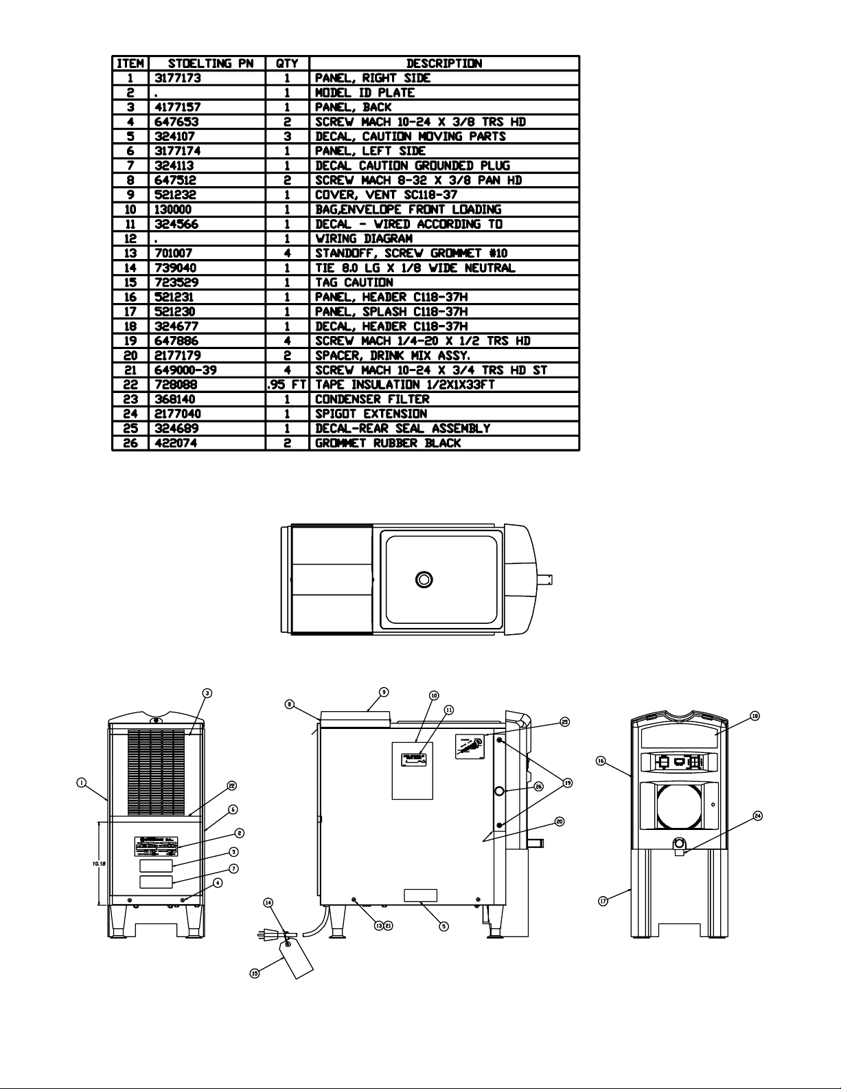
SECTION 9
PARTS LIST & DRAWINGS
4171820-SV Hopper & Evap. Assy . (Ser . #0-9994)
4172889 Back Panel (Ser . #0-9994)
4172948 Auger
4177157 Back Panel (Ser . #10,005 Plus)
4177158-SV Hopper & Evap. Assy. (Ser . #10,005 Plus)
3170878 Bearing Housing Assy.
3172953 R.H. - Side Panel
3172954 L.H. - Side Panel
31771 14 Front Panel
3177121-SV Front Door w/Pin (Ser . #10,005 Plus)
3172964-SV Front Door w/Pin (Ser. #0-9994)
2171834 Spigot Assy.
2172898 Front Lower Slotted Panel
2177040 Spigot Extension
2177123-SV Light Strip (Top) (Ser. #10,005 Plus)
2177160 Air Blockoff Panel
2172939 Probe Assy.
2172966-02SV 2 Light S trip (Sides) (Ser. #0-9994)
2172966-03SV 3 Light S trip (T op) (Ser . #0-9994)
1 106373 Spline Lubricant
1 120918 Splash Defelctor - Spigot Body
1 170836-SV Limit Switch - Door Safety
1 170836-TC Limit Switch - Torque Consistency
1 170882 Auger Bushing
1 172926 Drip Tray Grid
718768 Hi Pressure Limit Control Switch
718886 Rocker Switch - Clean/Off/On
718887 Rocker Switch - Serve/Standby , Lights On/Of f
739543 Timer Delay
744142 Transformer
744269 Drain Tray
756085 1/2" I.D. Tubing - Drain Tube (Per Foot)
762410 Expansion Valve
762978 EPR Valve
771004 Window - Front
771005 Window - Lower
618488 Relay Overload - Comp.
618530 Relay - Comp.
624607 O-Ring - Spigot Body
624857 O-Ring - Rear Seal
62531 1 Quad Ring - Front Door
647512 Screw - Vent Cover
647653 Panel Screw - Back Panel/Front Slotted Panels
649000-39 Panel Screw - Side Panels
667830 V-Ring Seal - Brg. Hsg. Assy.
667860 Shaft Seal - Brg. Hsg. Assy.
667892 Rear Seal
694400 Spring - Spigot Body
695763 Spring - T orque Consistency Adjustment
696130 Lock Clip - Spigot Body
31
Page 40

508135 Petro-Gel 4 oz. tube
513556 Owner's Manual
521227 Vent Cover (Ser. #0-9994)
521228 Hopper Cover
521229 Drip Tray
521230 Splash Panel
521231 Header Panel
521232 Vent Cover (Ser.#10,005 Plus)
522418 Motor - 1/3 HP
522833 Fan Motor - Condenser
598012 Pulley - Motor
598331 Pulley - Bearing Assy.
430168 Power Cord - 15 Amp.
454016 Idler
458104 Indicator Light - Mix Out
482004 Knob - T orque Consistency Adjustment
482024 Knob - Spigot Body
482043 Knob - Front Door
490725 Leg
490730 Non-Skid Pad - Leg
493063 Incandescent Light Bulb - 24V/5 Watt (Ser. #0-9994)
493064 Incandescent Light Bult - 24V/10 Watt (Ser. #10,005 Plus)
324014 Decal - Black Arrow on White
324105 Decal - Caution Elec. Shock
324107 Decal - Caution Moving Parts
3241 13 Decal - Caution Grounded Plug
324141 Decal - Caution Rotating Blades
324208 Decal - Refrig. Leak Check
324242 Decal - T emp. Adjustment
324566 Decal - Wired According to
324676 Decal - Switches
324677 Decal - Stowaway
324686 Decal - Danger Starts Automatic
324689 Decal - Seal Assy.
342006 Drier - Main
342020 Drier - Cap. Tube
368140 Condenser Filter
208401 Brush 1" x 3" x 10"
230624 Start Capacitor - Comp.
231 1 05 Cap. Tube
232002 Retaining Cap. - Spigot Body
264061 Jaw Type Clamp - Drain T ube
282022-SV Compressor - T ecumseh (w/caps)
284081 Condenser
29501 1 Contactor
296179 Liquid Level Control
296658 Temperature Control
146353 Bearing - Brg. Housing Assy.
146449 Bearing - Drive Motor
152227 V-Belt
162051 Fan Blade - 6" (rear)
162052 Fan Blade - 5" (front)
162067 Fan Blade - Condenser
162156 Scraper Blade
32
Page 41

3334353637383940414243
Page 42

Page 43

Page 44
Page 45

Page 46

Page 47

Page 48

Page 49

Page 50

Page 51

 Loading...