

Page 1

Model S100 / S400 / S500
OPERATORS MANUAL
Manual No. 513560
Page 2

Page 3

This manual provides basic information about the machine. Instructions and suggestions are
given covering its operation and care.
The illustrations and specifi cations are not binding in detail. We reserve the right to make
changes to the machine without notice, and without incurring any obligation to modify or provide new parts for machines built prior to date of change.
DO NOT ATTEMPT to operate the machine until instructions and safety precautions in this
manual are read completely and are thoroughly understood. If problems develop or questions
arise in connection with installation, operation, or servicing of the machine, contact Stoelting.
stoeltingfoodservice.com
Stoelting Foodservice Equipment
502 Highway 67
Kiel, WI 53042-1600
U.S.A.
Main Tel: 800.558.5807
Fax: 920.894.7029
Customer Service: 888.429.5920
Fax: 800.545.0662
Email: foodservice@stoelting.com
© 2014 PW Stoelting, LLC
Page 4

A Few Words About Safety
Safety Information
Read and understand the entire manual before
operating or maintaining Stoelting equipment.
This manual provides the operator with information
for the safe operation and maintenance of Stoelting
equipment. As with any machine, there are hazards
associated with their operation. For this reason safety
is emphasized throughout the manual. To highlight
specifi c safety information, the following safety defi ni-
tions are provided to assist the reader.
The purpose of safety symbols is to attract your attention to possible dangers. The safety symbols, and
their explanations, deserve your careful attention
and understanding. The safety warnings do not by
themselves eliminate any danger. The instructions
or warnings they give are not substitutes for proper
accident prevention measures.
If you need to replace a part, use genuine Stoelting
parts with the correct part number or an equivalent
part. We strongly recommend that you do not use
replacement parts of inferior quality.
Safety Alert Symbol:
This symbol Indicates danger, warning or caution.
Attention is required in order to avoid serious personal injury. The message that follows the symbol
contains important information about safety.
Signal Word:
Signal words are distinctive words used throughout
this manual that alert the reader to the existence and
relative degree of a hazard.
WARNING
The signal word “WARNING” indicates a potentially
hazardous situation, which, if not avoided, may result
in death or serious injury and equipment/property
damage.
CAUTION
The signal word “CAUTION” indicates a potentially
hazardous situation, which, if not avoided, may result
in minor or moderate injury and equipment/property
damage.
CAUTION
The signal word “CAUTION” not preceded by the
safety alert symbol indicates a potentially hazardous
situation, which, if not avoided, may result in equipment/property damage.
NOTE (or NOTICE)
The signal word “NOTICE” indicates information or
procedures that relate directly or indirectly to the
safety of personnel or equipment/property.
Page 5

TABLE OF CONTENTS
TABLE OF CONTENTS .................................................................................................................................... 2
SECTION 1 - INTRODUCTION ......................................................................................................................... 4
1.1 Description ........................................................................................................................................ 4
1.2 Specifications .................................................................................................................................... 4
SECTION 2 - SHIPMENT ................................................................................................................................. 5
2.1 Shipment and Transit........................................................................................................ ................. 5
2.2 Installation ......................................................................................................................................... 5
SECTION 3 - OPERATION INSTRUCTIONS.................................................................................................... 6
3.1 Operator's Safety Precautions ........................................................................................................... 6
3.2 Lil’ Shaver and Blender Controls ........................................................................................................ 6
3.3 Cleaning and Sanitizing ..................................................................................................................... 7
SECTION 4 - ADJUSTMENTS.......................................................................................................................... 8
4.1 Dispense Rate................................................................................................................................... 8
4.2 Shaver Motor Reset ........................................................................................................................... 8
SECTION 5 - ELECTRICAL .............................................................................................................................. 9
SECTION 6 - MECHANICAL............................................................................................................................. 12
SECTION 7 - TROUBLESHOOTING ................................................................................................................ 16
SECTION 8 - DRAWINGS AND WIRING DIAGRAMS ..................................................................................... 18
Page 6

ILLUSTRATIONS
Fig.1 - Drain Hose Connection ......................................................................................................................5
Fig.2 - Operation Safety................................................................................................................................. 6
Fig.3 - Operation Control ...............................................................................................................................6
Fig.4 - Adjusting Screw & Overload ............................................................................................................ 8
Fig.5 - Electrical Access.................................................................................................................................9
Fig.6 - Switch Removal..................................................................................................................................9
Fig.7 - Time Delay Relay ...............................................................................................................................10
Fig.8 - Drink Selector Switch.........................................................................................................................10
Fig.9 - Potentiometer .....................................................................................................................................10
Fig.10 - Safety Switch ...................................................................................................................................... 11
Fig.11 - Contactors ...........................................................................................................................................11
Fig.12 - Time Delay Relay ...............................................................................................................................11
Fig.13 - Shaver Blade Replacement...............................................................................................................12
Fig.14 - Shaver Blade ......................................................................................................................................12
Fig.15 - Blender Motor .....................................................................................................................................13
Fig.16 - Shaver Drive Motor............................................................................................................................. 14
Fig.17- Drive Bearings Assembly ...................................................................................................................14
Page 7

SECTION 1
INTRODUCTION
1.1 DESCRIPTION
The LIL' SHAVER® is a heavy-duty ice shaver and frozen
drink blending machine. This machine can be used to
make perfect frozen cocktails, fruit juices, slush drinks,
frozen coffee drinks, non-alcoholic drinks and more. The
instructions in this manual should be followed closely for
trouble-free operation.
1.2 SPECIFICATIONS
001S004S005S015S/505S
SNOITACIFICEPS
SNOISNEMID
htdiW
htpeD
thgieH
THGIEW )gk23(.sbl17)gk23(.sbl17)gk23(.sbl17)gk23(.sbl17
LACIRTCELE ,stlov511,esahP1
REVAHS
ROTOM
REDNELB
ROTOM
REPPOH
YTICAPAC
)mc6.82("3.11
)mc66("62
)mc66("62
drocpmA51.zh06
gninnur21;detcennoc
spma
tratsroticapac,pH52.tratsroticapac,pH52.tratsroticapac,pH52.tratsroticapac,pH52.
deeps2,pH34.
)MPR00041&00081(
snollag5.xorppA
.sbl32(ecidebuc
)001(.xorppa=)gk01
sknird.zo21
uc
)mc6.82("3.11
)mc3.05("12
)mc66("62
,stlov511,esahP1
drocpmA51.zh06
1;detcennoc
spma
gninnur2
deeps2,pH34.
)MPR00041&00081(
snollag5.xorppA
.sbl32(ecideb
)001(.xorppa=)gk01
sknird.zo21
)mc6.82("3.11
)mc3.05("12
)mc66("62
,stlov511,esahP1
drocpmA51.zh06
gninnur21;detcennoc
spma
deeps2,pH34.
)MPR00041&00081(
snollag5.xorppA
.sbl32(ecidebuc
)001(.xorppa=)gk01
sknird.zo21
)mc6.82("3.11
)mc3.05("12
)mc66("62
)mc08-"5.13thgieH015S(
.zh06,stlov511,esahP1
ocpmA51
llag5.xorppA
;detcennocdr
spmagninnur21
deeps2,pH34.
)MPR00041&00081(
ecidebucsno
.xorppa=)gk01.sbl32(
sknird.zo21)001(
).lag01.xorppa015S(
REDNELB
YTICAPAC
)egnardim(
REDNELB
*EMITNUR
)egnardim(
U/L approved
.lag2/1,.zo46
)retil2(
EMITEVAHS
.ces7.5-knirD1
.ces1.9-knirD2
.ces0.31-knirD3
irD3
.lag2/1,.zo46
)retil2(
.ces7.5-knirD1
.ces1.9-knirD2
.ces0.31-kn
1
.lag2/1,.zo46
)retil2(
.ces7.5-knirD1
.ces1.9-knirD2
.ces0.31-knirD3
*.ces6.5-knirD1
.ces0.9-knirD2
.ces1.31-knirD3
* Not all models
.lag2/1,.zo46
)retil2(
.ces8-knirD1
.ces11-knirD2
.ces41-knirD3
*.ces01-knirD1
.ces51-knirD2
.ces0
2-knirD3
Page 8

2
Page 9
SECTION 2
SHIPMENT
2.1 SHIPMENT AND TRANSIT
The LIL' SHAVER® has been completely assembled,
operated and inspected at the factory. Upon arrival at the
final destination, the ice shaver must be checked for any
damage that may have occurred during transit. THE
CARRIER IS RESPONSIBLE FOR ALL DAMAGE IN
TRANSIT,WHETHER VISIBLE OR CONCEALED. Do not
pay the freight bill until you have checked the equipment.
Have the carrier note any visible damage on freight bill. If
concealed damage and/or shortages are found later, advise the carrier inspector within ten days and request
inspection. You must make claim for damages and/or
shortages in shipment with the carrier. STOELTING, INC.,
CANNOT MAKE ANY CLAIMS AGAINST THE CARRIER.
2.2 INSTALLATION
A. Unbox the Lil’ Shaver
B. Place on a level, solid surface.
C. Adjust the rubber feet until the shaver is level and
resting solidly on all four feet. (Feet can be placed in
alternate locations to match various counter depths).
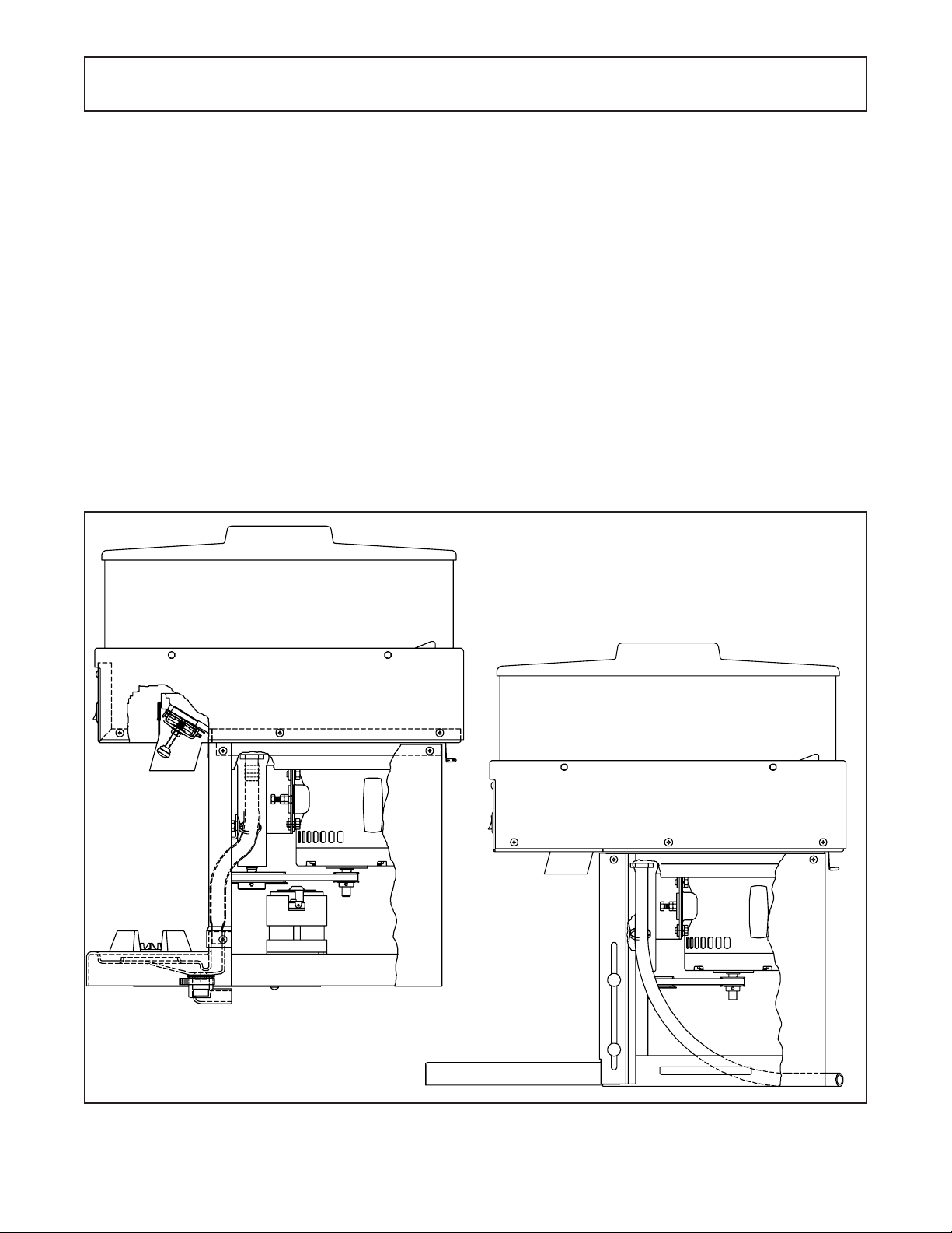
D. Connect the separate drain hose to the drain, and direct
the hose to a sink, floor drain or container. Liquid must
not cover the hose end or the unit will not drain properly.
(Figure 1)
E. Plug the 115 volt 15 amp cord plug into a dedicated
circuit. We do not recommend using an extension cord,
but if it is necessary to use one, it must be a number 12
gauge or heavier wire with a ground.
WARNING
DO NOT USE A GROUNDED ADAPTER PLUG OR
ALTER THE ELECTRICAL CORD IN ANY WAY.
FAILURE TO HEED THE WARNING COULD
CAUSE DAMAGE TO THE MACHINE OR PERSONAL INJURY.
Late
Early
Figure 1
Drain Hose Connection
S500 Shown
3
Page 10

4
Page 11
SECTION 3
OPERATOR INSTRUCTIONS
3.1 OPERATORS SAFTEY PRECAUTIONS
Safe operation is no accident; observe these rules:
A. Know the equipment. Read and understand the operat-
ing instructions.
B. Notice all warning labels on the equipment.
C. Wear proper clothing. Avoid loose-fitting garments, and
remove watches, rings or jewelry which could cause a
serious accident.
D. Maintain a clean work area. Avoid accidents by clean
ing up the area and keeping it clean.
E. Stay alert at all times. Know which switch, push button
or control you are about to use, and what effect it is
going to have.
F. Disconnect electrical cord for maintenance. Never at-
tempt to repair or perform maintenance on the unit until
the main electrical power has been disconnected.
G. Do not operate under unsafe operating conditions.
Never operate the machine if unusual or excessive
vibration occurs.
H. Do not operate the unit without the hopper cover and
hopper in place and intact. (Figure 2)
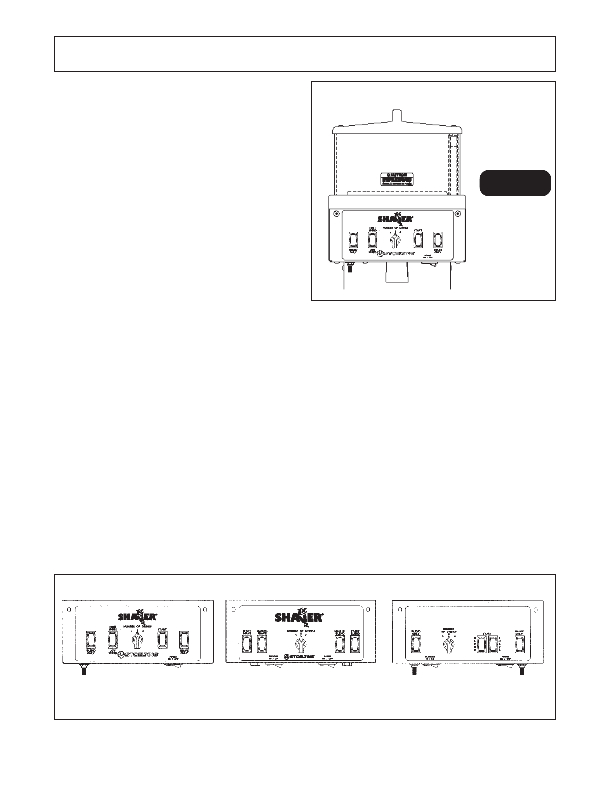
3.2 LIL’ SHAVER AND BLENDER CONTROLS
Before operating it is required the operator know the
function of each operation control. Refer to Figure 3 for
location of the operating controls on the machine.
Hopper Cover
ÌË
Hopper
Ë
CAUTION
HAZARDOUS ROTATING
PARTS. DO NOT OPERATE
Å
WITHOUT COVER OR HOPPER
IN PLACE.
Figure 2
Operation Safety
S100/S500 Shown
B. Blend Time Adjuster. To increase blend time (fine ice)
turn adjuster clockwise. To decrease blend time turn
adjuster counter-clockwise.
NOTE
Use a small screwdriver to adjust.
C. Blend Start Switch. When activated, the start switch
will blend the drink for the pre-set time.
A. The POWER ON/OFF switch. When the POWER ON/
OFF switch is placed in the OFF position, the machine
will not run. When the switch is placed in the ON
position the shaver and blender can be operated by
activating the appropriate switch.
S100/S500 S502+
S505/S510
Figure 3
Operation Controls
NOTE
Blender will not start until 2.2 seconds after the
shave switch has been activated. (Models 505/510)
5
Page 12

D. BLEND ONLY Switch when activated, the blender drive
will run until the switch is released.
E. HIGH SPEED/LOW SPEED Switch (models S100/
S500 only). When in the LOW SPEED position, the
blender drive operates at the lower speed when the
BLEND ONLY switch is activated. When in the HIGH
SPEED position, the blender drive will operate at the
higher speed when the BLEND ONLY switch is activated.
F. NUMBER OF DRINKS ROTARY Switch (models S100/
S500 series only).The NUMBER OF DRINKS switch
operates a timer. When the desired number of drinks
has been selected and the START switch activated, the
machine will shave enough ice for that number of drinks,
then stop.
WARNING
USE CAUTION WHEN ACCESSING THE ICE
SHAVING AREA. THE ICE SHAVING BLADE IS
EXTREMELY SHARP. CONTACT WITH THIS
BLADE COULD CAUSE INJURY .
B. Spray ice hopper and shaving area with an approved
cleaner/sanitizer.
C. Wash hopper cover in warm soapy water, rinse, then
sanitize and let dry.
CAUTION
DO NOT PUT ANY P ARTS THROUGH THE DISHWASHER. THESE PARTS ARE NOT DISHWASHER SAFE AND DAMAGE WILL OCCUR.
G. SHAVE TIME ADJUSTER to increase shave time
(more ice) turn adjuster clockwise. To decrease shave
time turn adjuster counter-clockwise.
NOTE
USE A SMALL SCREWDRIVER TO ADJUST .
H. Shave START Switch (models S100/S500 series only).
When activated, the START switch will shave ice for the
number of drinks selected, then stop.
I. SHAVE ONLY Switch. When the SHAVE ONLY switch
is activated, the machine will shave ice as long as the
switch is depressed. When released, it will stop.
3.3 Cleaning and Sanitizing
It is important to keep your LIL' SHAVER® clean and
sanitary. To properly clean and sanitize, follow the instructions below.
A. Remove ice from hopper by pressing the SHAVE ONLY
switch and dispensing into a container.
D. Disassemble blender following the steps outlined be
low.
1.Remove cover center knob (if used) by turning counter-
clockwise.
2.Remove blade assembly from bowl by turning counter-
clockwise viewed from driven end.
WARNING
NEVER GRASP THE BLADE ASSEMBL Y BY THE
CUTTING BLADES. THE BLADES ARE EXTREMEL Y SHARP AND COULD CAUSE INJUR Y
IF HANDLED IN A CARELESS MANNER.
3.Remove rubber gasket.
4.Clean all parts in warm soapy water, rinse, then
sanitize and let air dry.
5.Assemble all parts in reverse order.
6
Page 13
SECTION 4
ADJUSTMENTS
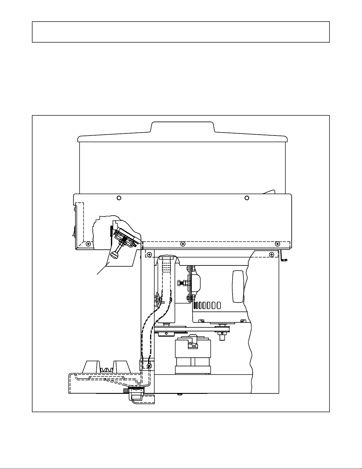
4.1 Dispense Rate
The rate of ice shaving can be adjusted by raising or
lowering the shaving blade. The adjusting screw is accessed from just behind the POWER ON/OFF switch.
Counter clockwise rotation of the adjusting knob gives a
faster dispense rate (more ice shaved in the same time.)
Make small (1/8 turn) changes in the adjusting screw until
the desired rate is achieved. (Figure 4)
4.2 Shaver Motor Reset
The machine’s shaver motor is equipped with an overload
devise to protect the motor and shaver. Manually reset this
protector by pulling the reset lever down. (Figure 4)
Ê
Adjusting Knob
Figure 4
Adjusting Screw and Overload
S500 Shown
Overload
Å
Reset
7
Page 14

8
Page 15
SECTION 5
ELECTRICAL
The control circuit consists of a combination of switches,
potentiometers, and time delay relays. The electrical controls along with an adjustable ice shaving blade allow the
operator to not only adjust the amount of ice shaved but
also the ice shaving size.
To gain access to the electrical controls perform the following procedures:
W ARNING
DISCONNECT SHAVER FROM THE SOURCE OF
ELECTRICAL SUPPL Y BEFORE SER VICING .
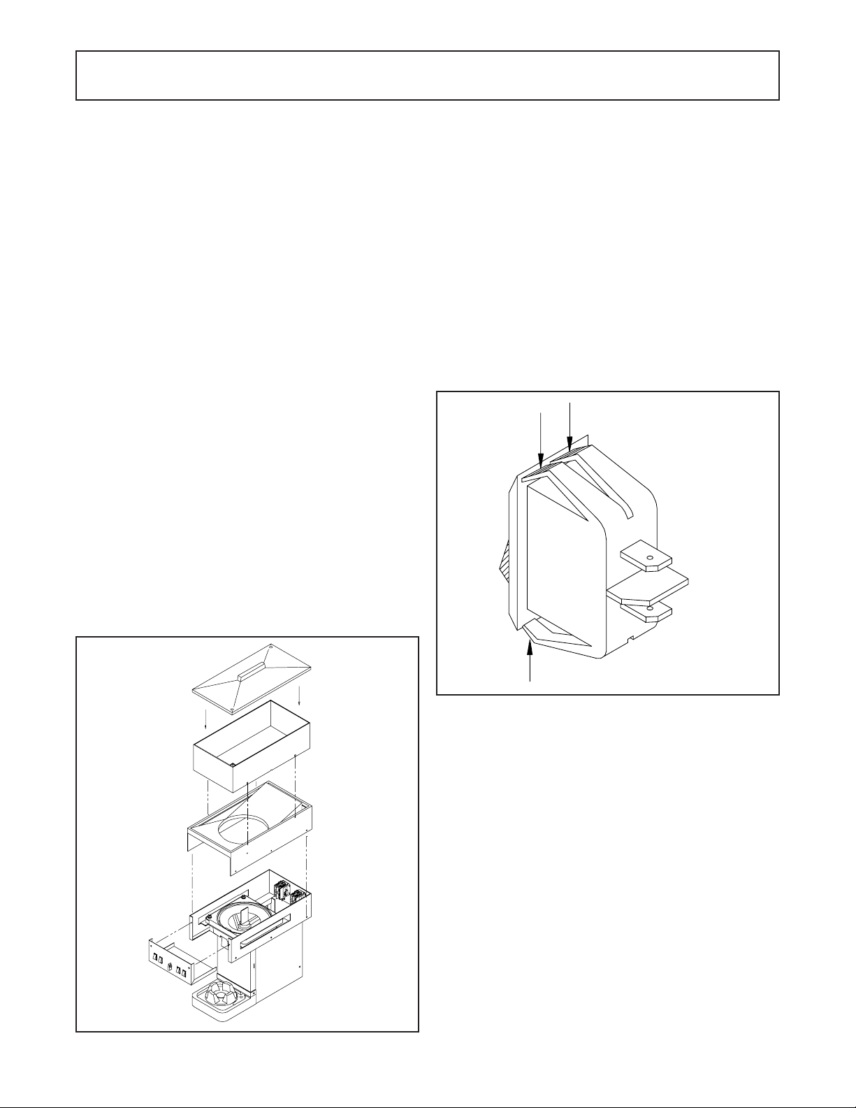
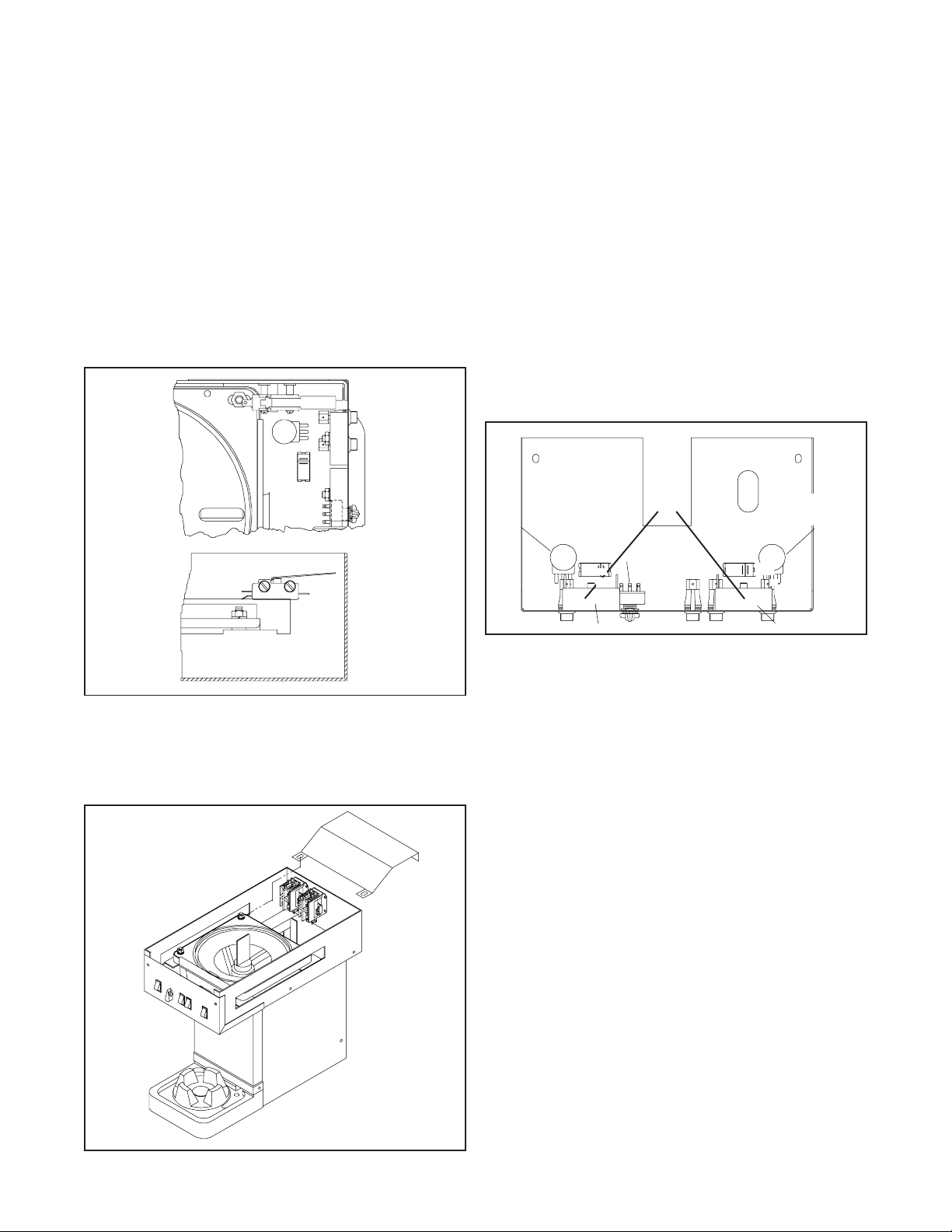
1. To access the front electrical box remove the six retaining screws, then pull down and out.
If additional room is desired to service the front electrical
box or if access to the contactors is required perform the
following procedures:
1. Remove the hopper cover. Figure 5.
2. Remove the four hand screws and lift the hopper up
and off.
3. Remove the seven screws holding the ice inlet chute,
then lift straight up.
4. T o provide access to the contactors remove the two
hex head nuts holding the contactor cover and lift off.
5. To access the time delay relays and the general
purpose relay, remove the lower sheet met al. Then
remove the two philips head screws and remove
electrical box cover. (Models 505/510 only .)
The components are now completely accessible and any
testing or service can be done.
IMPORTANT NOTE
When replacing electrical components identify wires
before removing or place the wires from the existing
component onto the replacement component one
at a time to avoid errors.
To replace electrical components perform the following
procedures:
Power on/off switch
1. Identify and remove the wires from the switch.
2. Squeeze the four retaining tabs together and push the
switch through the hole. Figure 6.
Fig. 5 - Electrical Access
Fig. 6 - Switch Removal
3. Push the replacement switch through the hole with the
red half of the rocker to the right side.
4. Reconnect the wires.
Blender High/Low Switch
1. Identify and remove the wires from the switch.
2. Squeeze the four retaining tabs together and push the
switch through the hole.
3. Push the replacement switch through the hole with the
red half of the rocker to the right side.
4. Reconnect the wires.
Blend Only Switch
1. Identify and remove the wires from the switch.
2. Squeeze the four retaining tabs together and push the
switch through the hole.
3. Push the replacement switch through the hole with the
protruding part of the rocker to the bottom.
4. Reconnect the wires.
9
Page 16
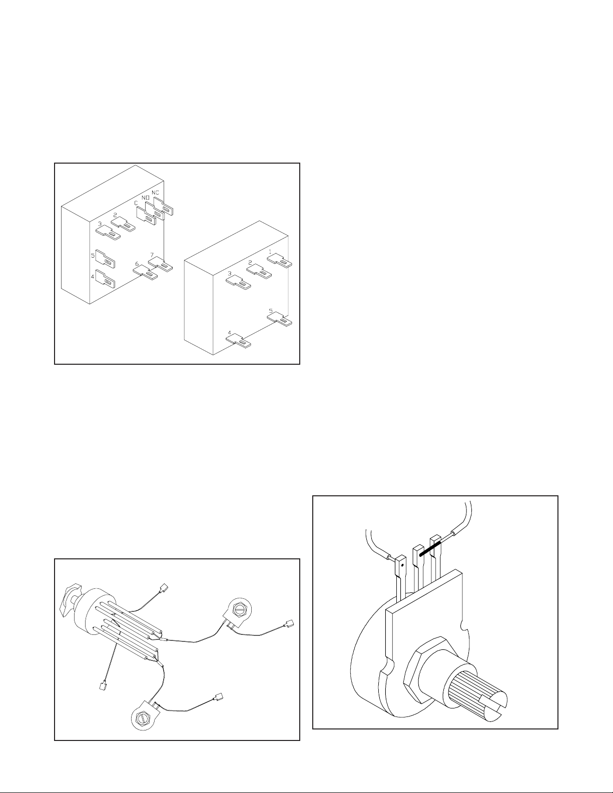
Drink Selector Switch
The selector switch is sold as an assembly that includes
the two potentiometers.
1. Remove the wire connecting the blender timer potentiometer to the time delay relay (Fig.7).
NOTE
On Models S505/S510 the time delay relays are
located in the rear of the shaver. Remove the lower
back sheet metal and electrical box cover to access.
Relay #1
Å
Relay #2
Æ
Blend Start Switch
1. Identify and remove the wires from the switch.
2. Squeeze the four retaining tabs together and push the
switch through the hole.
3. Push the replacement switch through the hole with the
protruding part of the rocker to the bottom.
4. Reconnect the wires.
Shave Start Switch
1. Identify and remove the wires from the switch.
2. Squeeze the four retaining tabs together and push the
switch through the hole.
3. Push the replacement switch through the hole with the
protruding part of the rocker to the bottom.
4. Reconnect the wires.
Shave Only Switch
1. Identify and remove the wires from the switch.
2. Squeeze the four retaining tabs together and push the
switch through the hole.
3. Push the replacement switch through the hole with the
protruding part of the rocker to the bottom.
4. Reconnect the wires.
Blend Potentiometer
1. Unsolder and remove the two wires.
Fig. 7 - Time Delay Relay
2. Remove the wire connecting the shave timer potentiometer to the time delay relay.
3. Remove the wire connecting the selector switch to the
blender time delay relay.
4. Remove the wire connecting the selector switch to the
shave time delay relay.
5. To remove the rotary selector switch knob loosen the
small set screw located at the bottom of the knob and
pull the knob off.
6. Remove the retaining nuts from the selector switch and
the two potentiometers (Fig.8). Then remove the complete assembly.
7. To install the replacement switch assembly reverse
steps 1 through 6.
Rotary Switch
Ë
Potentiometer
Ë
NOTE
Two legs of the potentiometer are jumpered, the replacement must be connected the same way.
2. Remove the retaining nut and remove the potentiometer. Take note where the shakeproof washer is
located.
3. Install the replacement potentiometer and shakeproof
washer, then install and tighten the retaining nut.
4. Reattach wires and solder.
Shave Potentiometer
1. Unsolder and remove the two wires.
Potentiometer
Fig. 8 - Drink Selector Switch
Æ
Fig. 9 - Potentiometer
10
Page 17
NOTE
Two legs of the potentiometer are jumpered, the replacement must be connected the same way
(Fig.9).
2. Remove the retaining nut and remove the potentiometer. Take note where the shakeproof washer is
located.
3. Install the replacement potentiometer and shakeproof
washer, then install and tighten the retaining nut.
4. Reattach wires and solder.
Safety Switch
1. Remove the three wires from the switch.
2. Remove the two retaining screws and spacers (Fig.10).
3. Install replacement switch using the spacers between
the switch and frame. Tighten screws.
3. Install replacement contactor with L1 & L2 terminals
up.
4. Install the star washers and hex nuts, then tighten
securely.
5. Reconnect the wires.
Shaver Contactor
1. Identify and remove the wires from the contactor.
2. Remove the two hex head nuts and star washers, then
lift out contactor.
3. Install replacement contactor with L1 & L2 terminals
up.
4. Install the star washers and hex nuts, then tighten
securely.
5. Reconnect the wires.
Blender Time Delay Relay
1. Identify and remove the wires from the delay relay.
2. Remove the hex head nut and star washer, then slide
off from weld stud (Fig.12).
Relay
Fig. 10 - Safety Switch
Blender Contactor
1. Identify and remove the wires from the contactor.
2. Remove the two hex head nuts and star washers, then
lift out contactor (Fig. 11).
Fig. 11 - Contactors
Fig. 12 - Time Delay Relay
3. Install the replacement part in the same position.
4. Install star washer and hex nut, then tighten.
5. Reconnect the wires.
Shaver Time Delay Relay
1. Identify and remove the wires from the time delay relay.
2. Remove the hex head nut and star washer, then slide
off from weld stud.
3. Install the replacement part in the same position.
4. Install star washer and hex nut, then tighten.
5. Reconnect the wires.
Blender Start Time Delay Relay (Some Models)
1. Remove the varistor.
2. Identify and remove the wires from the time delay relay.
3. Remove the hex head nut and start washers, then slide
off from weld stud.
4. Install replacement part in the same position.
5. Install star washer and hex nut, then tighten.
6. Reconnect the wires.
General Purpose Relay
1. Identify and remove wires from the relay.
2. Remove the two retaining screws and star washers.
3. Install the replacement part in the same position and
secure with the screws and star washers.
4. Reconnect the wires.
11
Page 18

12
Page 19

SECTION 6
MECHANICAL
W ARNING
WHEN WORKING ON MECHANICAL DEVICES
THAT ARE DESIGNED TO CUT, GRIND, OR
SHAVE, EXTREME CAUTION MUST BE EXERCISED. TAKE PROPER PRECAUTIONS WHEN
WORKING IN AREAS WHERE CUTTING BLADES
CAN BE CONT ACTED. FAILURE T O HEED THIS
WARNING COULD RESUL T IN INJUR Y .
Shaver Blade Replacement
1. Remove the six retaining screws from the electrical
box, then pull down and out.
2. Remove the protective strip (some models) and pull the
drip pan cover straight out (Fig.13).
ÈÈ
È
ÈÈ
Fig. 13 - Shaver Blade Replacement
3. Remove the ice discharge chute by removing the two
screws.
W ARNING
THE SHAVER BLADE IS EXTREMELY SHARP.
TAKE THE PROPER PRECAUTIONS TO AVOID
INJURY.
4. Remove the two screws holding the blade to the
bracket. (Fig. 14)
Bowl
Ì
Ê
Ê
6. Fasten the replacement blade to the bracket with the
two screws and tighten securely.
7. Install the ice discharge chute and secure with the two
screws.
8. Install the drip pan cover and protective strip.
9. Install the electrical box and secure with the six
screws.
Blender Drive Clutch Replacement
1. To remove the clutch hold the shaft with a straight
bladed screwdriver and turn the clutch clockwise (left
hand thread).
2. To install, thread the replacement clutch onto the shaft
counter-clockwise. Then hold the shaft with a straight
bladed screwdriver and tighten.
NOTE
Some early models did not have the screwdriver slot
in the shaft. Access from the bottom and hold the
pulley to remove the clutch.
Major Component Replacements
For major component replacements, you must first remove
the necessary sheet metal and plastic panels. Then
remove the four screws and star washers holding the
slotted cover at the bottom of the unit.
Bearing Replacement
When replacing bearings and seals a few simple rules
must be followed to secure longevity of the replacement
parts.
1. Make certain you have all the parts and tooling to
complete the job.
2. Maintain a clean work area.
3. Follow all instructions furnished with parts and/or tooling.
4. Make certain all set screws are loosened or removed
and remove all snap rings before pressing out parts.
5. Use proper tooling when pressing out parts to avoid
damage.
6. Thoroughly clean all parts to be reused.
7. When pressing in bearings or shafts, use tooling that
contacts the bearing race offering the greatest resistance.
Screws
Fig. 14 - Shaver Blade
5. Properly dispose of the used blade.
Blender Drive Bearing Replacement
1. Remove the blender drive clutch by holding the shaft
with a straight bladed screwdriver and turning the clutch
counter-clockwise (left hand thread).
2. Loosen the four retaining nuts holding the blender drive
motor mounting plate and slide toward the front to
loosen the belt.
3. Remove the drive belt.
4. Remove the blender drive pulley by loosening the two
set screws and pulling straight off.
13
Page 20

NOTE
For disassembly see parts breakdown on Pg.20.
4. Loosen the shaver drive motor adjustment screw and
remove the belt.
5. Remove the wave washer and flat washer.
6. Remove the flat head countersunk screws and remove
the bearing assembly.
7. Remove the shaft and flat washer from the bearing
assembly (slip fit). If stuck use a small arbor press.
8. To remove the bearings use an inside bearing puller. An
alternate method is to place the bearing retainer with
the small end down inside a 1-1/4" socket or a short
piece of pipe on a solid surface. Then using a small drift
punch and hammer go through the top bearing to the
lower bearing and tap the inner race moving the punch
after each tap in a circular motion. The second bearing
can be pushed out with a small arbor press.
9. Inspect the bearing retainer for any damage, if damaged
replace.
10.Use a small arbor press to push in the replacement bearings, use a tool that fully contacts the outer
race to avoid damaging the replacement bearing.
NOTE
Many bearings are destroyed during assembly because of improper assembly methods and tooling.
Pressure exerted on the race offering little or no resistance to push on a race of offering a much greater
resistance can cause cracks in the balls or race
and ultimate failure.
11.Reverse steps 1 through 7 to reassemble and replace
sheet metal and plastic panels.
Blend Motor Replacement
1. Cut the three wire ties.
NOTE:
Mark the location of the pulley’s before removing. When
re-installing pulleys make certain one of the set screws is
centered on the flat of the shaft if applicable.
5. Remove the pulley from the shaver motor by loosening
the two set screws and sliding the pulley off.
6. Loosen the two set screws on the impeller drive pulley.
7. Remove the four hex head screws from the blender drive
mounting plate, and move to the side. You can now
remove the impeller drive pulley and lift out the blender
drive assembly.
8. Loosen the two set screws on the blender motor pulley,
then turn counter-clockwise to remove. (Left hand
thread)
9. Remove the two ground wires by removing the hex head
nut and star washer.
10.Remove the four retaining screws and star washers to
separate the motor from the mounting plate.
11.To reassembly reverse steps 3 through 10, then reconnect the necessary wires securely.
12.Protect brush retainers with electrical tape.
Shave Motor Replacement
1. Cut the tie strap holding the black and white wires
leading from the drive motor to the terminal block and
contactor.
2. Loosen the belt tension adjustment screws by first
loosening the jam nuts then turning the adjustment
screw counter-clockwise (Fig.16).
NOTE
Identify wires before removing.
2. Cut the wires necessary for motor removal as close to
the connector as possible.
3. Loosen the four hex head screws and move the blender
motor forward then remove the belt (Fig.15).
Fig. 16 - Shaver Drive Motor
3. Remove the drive belt.
4. Remove the cap screws holding the drive motor to the
mounting bracket. Lower the motor down and out the
back.
5. Remove the electrical cover from the motor and disconnect the necessary wires.
Fig. 15 - Blender Motor
14
Page 21

NOTE
All motor wires are identified with letters and numbers.
Make a note of which wires go where.
6. Loosen the two set screws and remove the pulley.
7. Remove the two screws and remove the reset lever
assembly.
8. To reassemble reverse steps 1 through 7.
Shaver Bearing Replacement
1. To remove the front electrical box, remove the six
retaining screws and pull down and out.
2. Remove the agitator and impellor. Refer to Pg.19.
3. Remove the shaver drive motor. Refer to Pg.13.
4. Remove the two cap screws and lock washers holding
the drive bearing assembly to the frame (Fig.17).
5. Remove the two screws and spacers from the safety
switch and move the safety switch to the side.
6. Remove the four hex head nuts and the lock washers
from the bowl.
7. Remove the contactor cover.
NOTE
Cover the ice blade with a couple layer of duct tape
to avoid injury when removing the bowl from the shaver
frame.
8. Lift the bowl and drive bearing assembly up and out.
9. Remove the drive pulley by loosening the two set
screws and sliding off.
10.Remove the four cap screws and lock washers holding
the drive motor bracket to the drive bearing assembly
and remove the bracket.
1 1.Remove the four cap screws and lock washers holding
the drive bearing assembly to the bowl and separate.
12.Remove the snap ring from the shaft, then use an
arbor press to press the shaft out through the top.
NOTE
Use proper tooling when pressing out bearings to
avoid damage to the castings.
Fig. 17 - Drive Bearing Assembly
13.Press out the lower bearing, then the top bearing and
seal.
NOTE
When replacing bearings you must replace seals to
protect the bearings.
15
Page 22

16
Page 23

SECTION 7
TROUBLESHOOTING
melborP esuaC noitcerroC
.snurgnihtoN.nideggulptoN.gulpkcehC
esufrodeppirTrekaerB
.ecalperroteseR
.nwolb
wsytefaS.revocreppohkcehC
.detavitcatonhcti
.hctiwsffo/noytluaF.hctiwsecalpeR
-nrutt'nseodrellepmI
.snurrednelb
htrotoM
.deppirt
daolrevolamre
.daolrevo
rellepmimorfgnissimyeK
.yekecalpeR
teser&loocotrotomwollA
.tfahs
.demmajrellepmI.n
oitcurtsborofrellepmikcehC
.nekorbroffotleBfiecalper,tlebkcehC
.yrassecen
.nekorbroffosyelluPfiecalper,sye
llupkcehC
.yrassecen
.gnisolctonrotcatnoC.tiucrictolipkcehC
.deziesgniraeB.sgniraebecalpeR
.rotomytluaF.roto
,nurt'nseodrednelB
.snrutrellepmi
.daolrevo
lamrehtnotuorotomrednelB
mecalpeR
rofsetunim02ot51tiaW
daolrevo
.teserot
.nekorbroffotleBfiecalper,tlebkcehC
.yrassecen
.deziessgniraeB.sgniraebecalpeR
.nekorbroffosyelluPf
iecalper,syellupkcehC
.yrassecen
.gnisolctonrotcatnoC.tiucrictolipkcehC
17
Page 24

melborP esuaC noitcerroC
t'nseodtubsnrutrellepmI
.reppohniecioN.ecihtiwlliF
.eciesnepsid
.reppohnidegdirbecI.ecipukaerB
cecIeciraelcneht,revahsgulpnU
.dekcolbetuh
.etuhc
fotuoedalbgnivahS
.edalbgnivahstsujdaeR
.tnemtsujda
.enifootgnivahsecI.
.esraocootgnivahsecI.hgihoottesedalbgnivahS.noitisoprewol
.potstonlliwrevahsecIrohctiwsrotcelesytluaF
.gniriwgnitcennoc
woloottesedalbgnivahS.noitisoprehgihaotedalbteS
aotedalbteS
,hctiwsdnagniriwkcehC
.yrassecenfiecalper
.remitytluaF.remitecalpeR
.retemoitnetopytluaF.retemoitnetopecalpeR
18
Page 25

S100
S500/502+
SECTION 8
DRAWINGS
19
Page 26

2021222324
Page 27

Page 28

Page 29

Page 30

NOTE:
Left hand thread, turn
clockwise to loosen while
holding clutch
Page 31

2526272829
Page 32

Page 33

Page 34

Page 35

Page 36

NOTE
Location of contactors may vary .
30
Page 37

S100
S500/S502+
5/8" Mid-Span
31
Page 38

32
Page 39

S505/S510
33
Page 40

34
Page 41

S200
35
Page 42

36
Page 43

S300
37
Page 44

38
Page 45

S500
39
Page 46

40
Page 47

LS500
Some Models
41
Page 48

42
Page 49

S502
43
Page 50

44
Page 51

S505/S510
NOTE
See Page 46
45
Page 52

46
Page 53

S505/S510
47
Page 54

48
 Loading...