

Stoelting O431-38I2F Operators Manual

Model O431I2F
OPERATORS MANUAL
Manual No. 513678 Rev.1


This manual provides basic information about the machine. Instructions and suggestions are
given covering its operation and care.
The illustrations and specifi cations are not binding in detail. We reserve the right to make
changes to the machine without notice, and without incurring any obligation to modify or provide new parts for machines built prior to date of change.
DO NOT ATTEMPT to operate the machine until instructions and safety precautions in this
manual are read completely and are thoroughly understood. If problems develop or questions
arise in connection with installation, operation, or servicing of the machine, contact Stoelting.
stoeltingfoodservice.com
Stoelting Foodservice Equipment
502 Highway 67
Kiel, WI 53042-1600
U.S.A.
Main Tel: 800.558.5807
Fax: 920.894.7029
Customer Service: 888.429.5920
Fax: 800.545.0662
Email: foodservice@stoelting.com
© 2014 PW Stoelting, LLC

A Few Words About Safety
Safety Information
Read and understand the entire manual before
operating or maintaining Stoelting equipment.
This manual provides the operator with information
for the safe operation and maintenance of Stoelting
equipment. As with any machine, there are hazards
associated with their operation. For this reason safety
is emphasized throughout the manual. To highlight
specifi c safety information, the following safety defi ni-
tions are provided to assist the reader.
The purpose of safety symbols is to attract your attention to possible dangers. The safety symbols, and
their explanations, deserve your careful attention
and understanding. The safety warnings do not by
themselves eliminate any danger. The instructions
or warnings they give are not substitutes for proper
accident prevention measures.
If you need to replace a part, use genuine Stoelting
parts with the correct part number or an equivalent
part. We strongly recommend that you do not use
replacement parts of inferior quality.
Safety Alert Symbol:
This symbol Indicates danger, warning or caution.
Attention is required in order to avoid serious personal injury. The message that follows the symbol
contains important information about safety.
Signal Word:
Signal words are distinctive words used throughout
this manual that alert the reader to the existence and
relative degree of a hazard.
WARNING
The signal word “WARNING” indicates a potentially
hazardous situation, which, if not avoided, may result
in death or serious injury and equipment/property
damage.
CAUTION
The signal word “CAUTION” indicates a potentially
hazardous situation, which, if not avoided, may result
in minor or moderate injury and equipment/property
damage.
CAUTION
The signal word “CAUTION” not preceded by the
safety alert symbol indicates a potentially hazardous
situation, which, if not avoided, may result in equipment/property damage.
NOTE (or NOTICE)
The signal word “NOTICE” indicates information or
procedures that relate directly or indirectly to the
safety of personnel or equipment/property.

TABLE OF
CONTENTS
Section Description Page
1 Description and Specifi cations
1 Description ..................................................................................................1
1.2 Specifi cations .............................................................................................2
2 Installation Instructions
2.1 Safety Precautions .....................................................................................3
2.2 Shipment and Transit ..................................................................................3
2.3 Machine Installation ....................................................................................3
2.4 Installing Permanent Wiring ........................................................................3
2.5 Mix Pump ....................................................................................................4
2.6 IntelliTec2™ Setup ......................................................................................6
3 Initial Set-Up and Operation
3.1 Operator’s Safety Precautions ...................................................................9
3.2 Operating Controls and Indicators ..............................................................9
3.3 Disassembly of Machine Parts ...................................................................10
3.4 Cleaning Disassembled Parts ....................................................................11
3.5 Sanitizing Machine Parts ............................................................................11
3.6 Cleaning the Machine .................................................................................11
3.7 Assembling the Machine ............................................................................12
3.8 Sanitizing ....................................................................................................12
3.9 Freeze Down and Operation ......................................................................13
3.10 Mix Information ...........................................................................................14
3.11 Operation of Mix Pump ...............................................................................14
3.12 Mix Pump Cleaning ....................................................................................15
3.13 Disassembly and Inspection of Removable Parts ......................................15
4 Maintenance and Adjustments
4.1 Overrun Adjustment ....................................................................................17
4.2 Mix Pump Hose Reposition ........................................................................17
4.3 Mix Pump Hose Replacement ....................................................................18
4.4 Fine Consistency Adjustment .....................................................................18
4.5 Drive Belt Tension Adjustment ....................................................................19
4.6 Condenser Cleaning (Air-Cooled Machines) ..............................................19
4.7 Preventative Maintenance ..........................................................................19
4.8 Extended Storage .......................................................................................19

Section Description Page
5 Troubleshooting
5.1 Error Codes ................................................................................................21
5.2 Troubleshooting - Error Codes ...................................................................21
5.3 Troubleshooting - Machine .........................................................................23
5.4 Troubleshooting - Mix Pump .......................................................................24
6 Replacement Parts
6.1 Brushes, Decals and Lubrication ................................................................27
6.2 Spigot Extension .........................................................................................27
6.3 Auger Shaft and Faceplate Parts ...............................................................28
6.4 Cab Tubing Assembly .................................................................................29
SECTION 1
DESCRIPTION AND SPECIFICATIONS
1.1 DESCRIPTION
The Stoelting O431 I2 fl oor model machine is pressure
fed. The machine is equipped with fully automatic controls
to provide a uniform product. The machine is designed
to operate with almost any type of commercial soft-serve
or non-dairy mix available, including ice milk, ice cream,
yogurt, and frozen dietary desserts.
This manual is designed to assist qualifi ed service per-
sonnel and operators in the installation, operation and
maintenance of the Stoelting O431 I2 pressure machine.
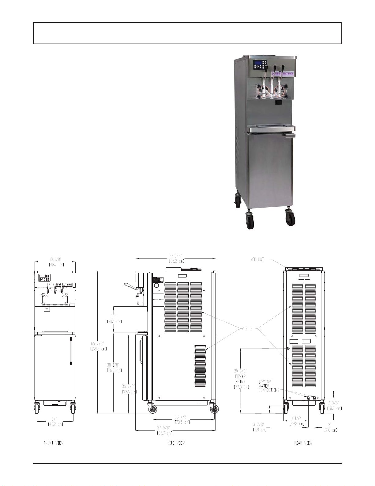
Figure 1-1 Model O431 I2
Owner’s Manual #513678 1 O431 I2 Model Machines

1.2 SPECIFICATIONS
Model O431 I2
Dimensions Machine with crate
width 19-1/8’’ (48,6 cm) 27’’ (68,6 cm)
height 66-7/8’’ (169,9 cm) 78’’ (198,1 cm)
depth 37-5/8’’ (95,6 cm) 48’’ (121,9 cm)
Weight 500 lbs (226,7 kg) 650 lbs (294,8 kg)
Electrical 1 Phase, 208-240 VAC, 60Hz 3 Phase, 208-240 VAC, 60Hz
Air Cooled Water Cooled Air Cooled Water Cooled
running amps
connection type
International Option 1 Phase, 220-240 VAC, 50Hz or 3 Phase, 380-415 VAC, 50Hz
Compressor
Compressor 15,000 Btu/hr Scroll™ Compressor
Drive Motor Two - 2 hp
23A 22A 19A 18A
NEMA L6-30P NEMA L6-30P NEMA L15-30P NEMA L15-30P
15,000 Btu/hr
Cabinet - 1,300 Btu/hr Compressor (R-134a)
Air Flow
Air cooled units require 3” (7,6 cm) air space on both sides and back and open
at the top.
Water cooled units require 1/2” N.P.T. water and drain fi ttings. Maximum water
Plumbing Fittings
pressure of 130 psi. Minimum water fl ow rate of 3 GPM per barrel. Ideal EWT
of 50°-70°F.
Hopper Volume Two - 5.5 gallons (20,82 liters)
Freezing Cylinder
Volume
Two - 1 gallon (3,79 liters)
Owner’s Manual #513678 2 O431 I2 Model Machines
SECTION 2
INSTALLATION INSTRUCTIONS
2.1 SAFETY PRECAUTIONS
Do not attempt to operate the machine until the safety
precautions and operating instructions in this manual are
read completely and are thoroughly understood.
Take notice of all warning labels on the machine. The labels have been put there to help maintain a safe working
environment. The labels have been designed to withstand
washing and cleaning. All labels must remain legible for
the life of the machine. Labels should be checked periodically to be sure they can be recognized as warning labels.
If danger, warning or caution labels are needed, indicate
the part number, type of label, location of label, and quantity
required along with your address and mail to:
STOELTING, INC.
ATTENTION: Customer Service
502 Hwy. 67
Kiel, Wisconsin 53042
2.2 SHIPMENT AND TRANSIT
The machine has been assembled, operated and inspected
at the factory. Upon arrival at the fi nal destination, the
entire machine must be checked for any damage which
may have occurred during transit.
With the method of packaging used, the machine should
arrive in excellent condition. THE CARRIER IS RESPONSIBLE FOR ALL DAMAGE IN TRANSIT, WHETHER
VISIBLE OR CONCEALED. Do not pay the freight bill
until the machine has been checked for damage. Have
the carrier note any visible damage on the freight bill. If
concealed damage and/or shortage is found later, advise
the carrier within 10 days and request inspection. The
customer must place a claim for damages and/or shortages in shipment with the carrier. Stoelting, Inc. cannot
make any claims against the carrier.
2.3 MACHINE INSTALLATION
WARNING
Installation must be completed by a qualifi ed
electrician/refrigeration specialist.
Incorrect installation may cause personal injury,
severe damage to the machine and will void factory warranty.
Installation of the machine involves moving the machine
close to its permanent location, removing all crating, setting in place, assembling parts, and cleaning.
PRIOR TO INSTALLATION
A. Locate a copy of the service contact fi le (info.txt).
B. Modify the info.txt fi le with information from the
service company using the instructions in the fi le.
C. Put the service contact fi le onto the root level of
a USB fl ash drive (do not put the fi les into any
folder).
INSTALLATION
A. Uncrate the machine.
B. Install the four casters. Turn the threaded end
into the machine until no threads are showing. T o
level, turn out casters no more than 1/4” maximum,
then tighten all jam nuts.
C. The machine must be placed in a solid level
position.
NOTE
Accurate leveling is necessary for correct drainage
of freezing cylinder and to insure correct overrun.
D. Machines with air-cooled condensers require 3”
(7,6 cm) air space on both sides and back for
proper circulation.
F . In air-cooled machines, use a voltmeter to measure
incoming voltage. If the supply voltage is 215 or
less, remove the right side panel and move the
voltage selector toggle switch to the 208V position.
NOTE
Supply voltage must be checked to make sure the
fan motor operates properly.
E. Machines that have a water-cooled condenser
require 1/2” NPT supply and drain fi ttings. Turn
on the water supply and check for leaks.
2.4 INSTALLING PERMANENT WIRING
If permanent wiring is required by local codes, the following procedure must be performed:
A. Refer to the nameplate on the side panel of the
machine for specifi c electrical requirements. Make
sure the power source in the building matches
the nameplate requirements.
NOTE
Three phase machines in areas of unbalanced
electrical loads require special attention when connecting input electrical power. The unbalanced leg
of power (called wild or high) must be connected
to L2 in the junction box.
B. Remove the back panel and the junction box
cover located at the bottom of the machine.
Owner’s Manual #513678 3 O431 I2 Model Machines
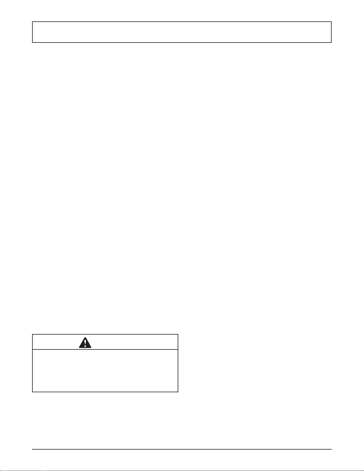
6” (15cm)
Figure 2-2 Mix Hose Installation
C. Install permanent wiring according to local code.
D. Check the auger shaft rotation by pressing the
Main Power On/Off button and pressing the On/Off
Left or On/Off Right button. The Motor Calibration
screen will be displayed.
E. Move the cursor over the Left side and press the
SEL button then move the cursor over the Right
side and press the SEL button.
F . Auger shaft rotation is clockwise as viewed through
the clear front door.
G. Press the left arrow button to stop the augers
after checking the rotation.
NOTE
Press the left arrow button to exit the calibration
before the 5 minute timer expires. Motor calibration
will be completed in Section 2.6 and must be done
with sanitizer in the freezing cylinders.
2.5 MIX PUMP
A. MIX PUMP HOSE INSTALLATION
Follow the steps below to install the mix pump hose in
the cabinet part of the machine.
1. Turn the mix pump on by pressing the Pump On/
Off button on the touchpad.
2. Feed one end of the mix pump hose into the
entering or pickup hose side (left) of black cover
(Fig 2-2).
NOTE
Feed the tube into the clamp so the natural curve of
the tube is towards the outside of the black cover.
This prevents the hose from looping around the
black cover twice.
3. Gently push the hose into the black cover until it
begins to feed.
4. Allow the hose to feed itself through the pump
until about 6” (15cm) remains on the entering
side.
5. Turn the pump off.
6. Connect the mix pump hose to the elbow fi tting
(located on the left side of the mix line manifold)
using a small hose clamp. Be careful not to twist
the mix hose.
7. Turn the pump on.
8. Allow the remaining 6” (15cm) of tubing to feed
through pump until the hose adapter prevents
further feeding.
9. Turn the pump off.
CAUTION
Risk of Product Damage
Air/Mix Tee must remain below the black cover
clamp. If the T ee is above the pump, mix may drain
into the air compressor resulting in pump damage.
Owner’s Manual #513678 4 O431 I2 Model Machines
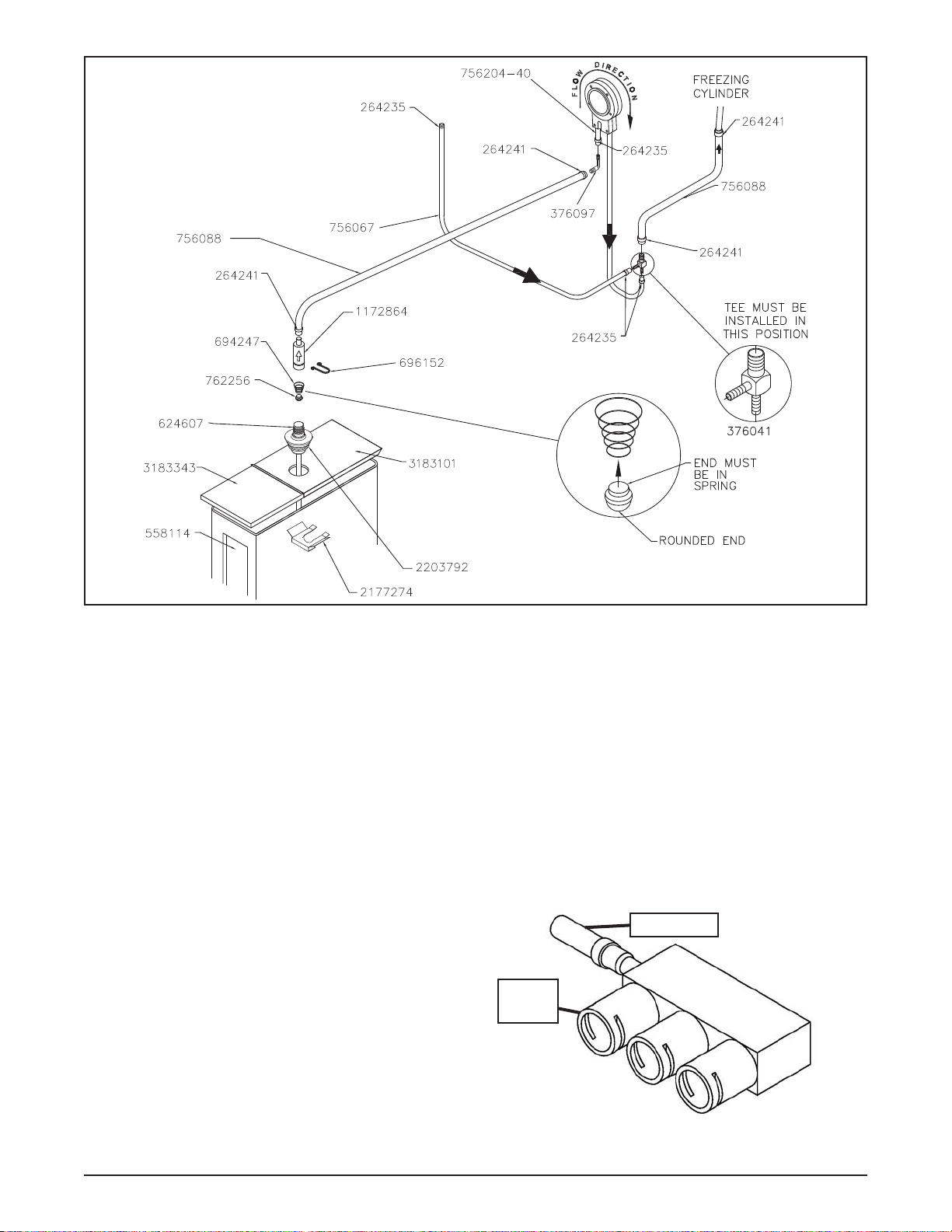
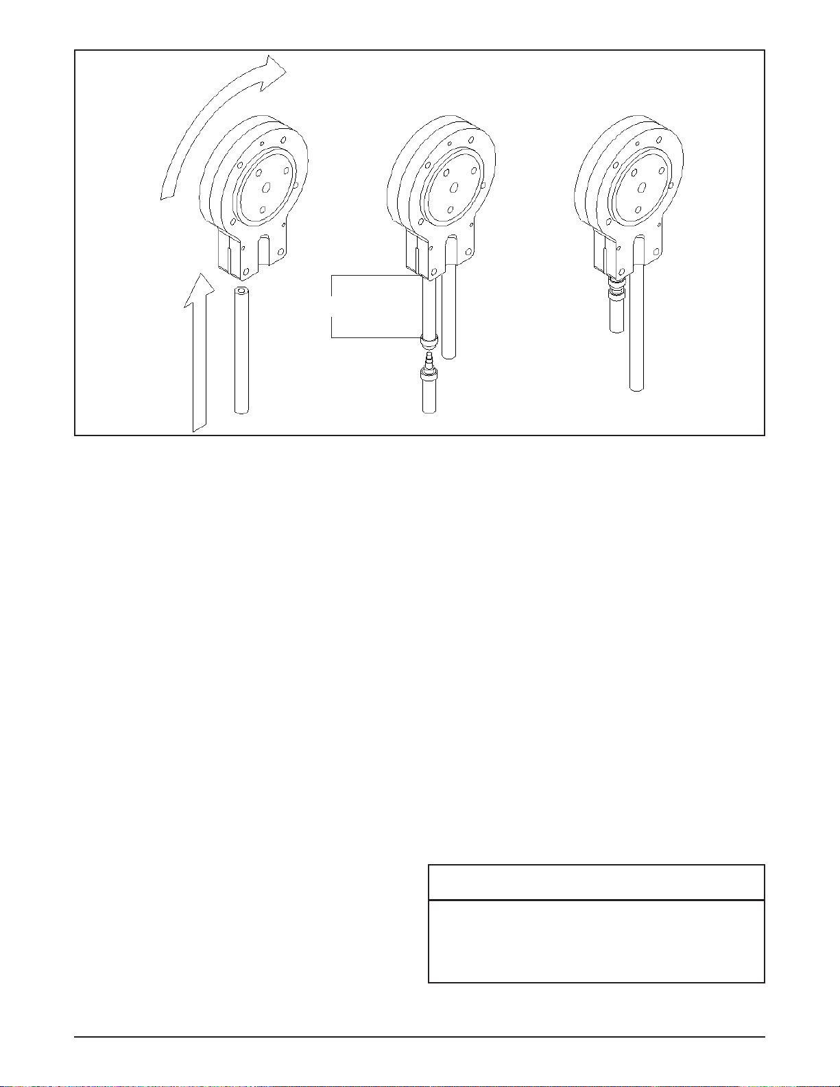
Figure 2-3 Mix Pump Connections for Standard Mix Container
10. Connect the free end of the mix pump hose to
the 3-way Tee (Fig. 2-3). When all connections
are complete, the 3-way Tee must be lower than
the black pump housing.
B. MIX PICKUP HOSE INSTALLATION
The O431 machine may be connected to the standard mix
container or up to three prepacked mix bags. Follow the
instructions below that match your confi guration.
Standard Connection:
1. Place the mix pickup assembly through the hole
in the cover and install the retaining clip.
2. Connect a 24” (61cm) length of 3/8” (9,5mm)
ID plastic food grade tubing to the mix pickup
assembly and secure with a hose clamp.
3. Connect the elbow fi tting to the free end of the
tubing. Connect the opposite end of the elbow
to 1/4” ID tan tubing on the left side of the pump
head. Secure with hose clamps (Fig. 2-3).
When Using Bag Connection System (BCS) with Three
Bags (optional kit #2183987):
The position of the three bags in the mix container is
important. The bag that is connected nearest the outlet
of the manifold will drain last and should be placed at
the back of the mix container. The mix low level indicator
relies on proper bag placement.
1. Connect 3/8” (9,5mm) ID plastic food grade tubing
to a bag adapter. Secure with hose clamps.
2. Slide the hose clip over free end of 3/8” (9,5mm)
ID plastic food grade tubing. Attach the free end
of the tubing to a manifold adapter. Secure with
a large hose clamp or equivalent.
3. Push the manifold adapter with spring and valve
into the left port (nearest the manifold outlet) of
the mix inlet manifold and secure with a retaining
clip. (Fig. 2-5).
4. Repeat steps 1 to 3 for the middle port and for
the right port of the mix inlet manifold.
Mix Outlet
Drains
Last
Figure 2-4 BCS Mix Inlet Manifold
Owner’s Manual #513678 5 O431 I2 Model Machines
5. Place three mix bags into the mix container.
6. Connect the bag adapter attached to the left side
of the manifold (closest to the mix outlet) to the
mix bag in the back of the mix container.
7. Connect the bag adapter attached to the middle
of the manifold to the mix bag in the middle of
the mix container.
8. Connect the bag adapter attached to the right
side of the manifold (farthest from the mix outlet)
to the mix bag in the front of the mix container.
When Using Bag Connection System (BCS) with One
or Two Bags (optional kit #2183987):
When connecting one or two bags, the manifold adapters must be installed closest to the manifold outlet and
the manifold plug(s) must be placed farthest from the
manifold outlet.
1. Connect 3/8” (9,5mm) ID plastic food grade tubing
to a bag adapter. Secure with hose clamps.
2. Slide the hose clip over the free end of the tubing.
Attach the free end of the tubing to a manifold
adapter. Secure with a large hose clamp.
3. Push the manifold adapter with spring and
valve into the left port (nearest
the manifold outlet) of the mix
inlet manifold and secure with
retaining clip. (See Figure 2-5).
4. If using two mix bags, repeat
steps 1 to 3 for the middle port.
5. Install a manifold plug into each
empty inlet and secure with a
retaining clip.
6. Place the mix bag(s) into the mix
container.
7. Connect the bag adapter
attached to the left side of the
manifold (closest to the mix
outlet) to the mix bag in the back
of the mix container.
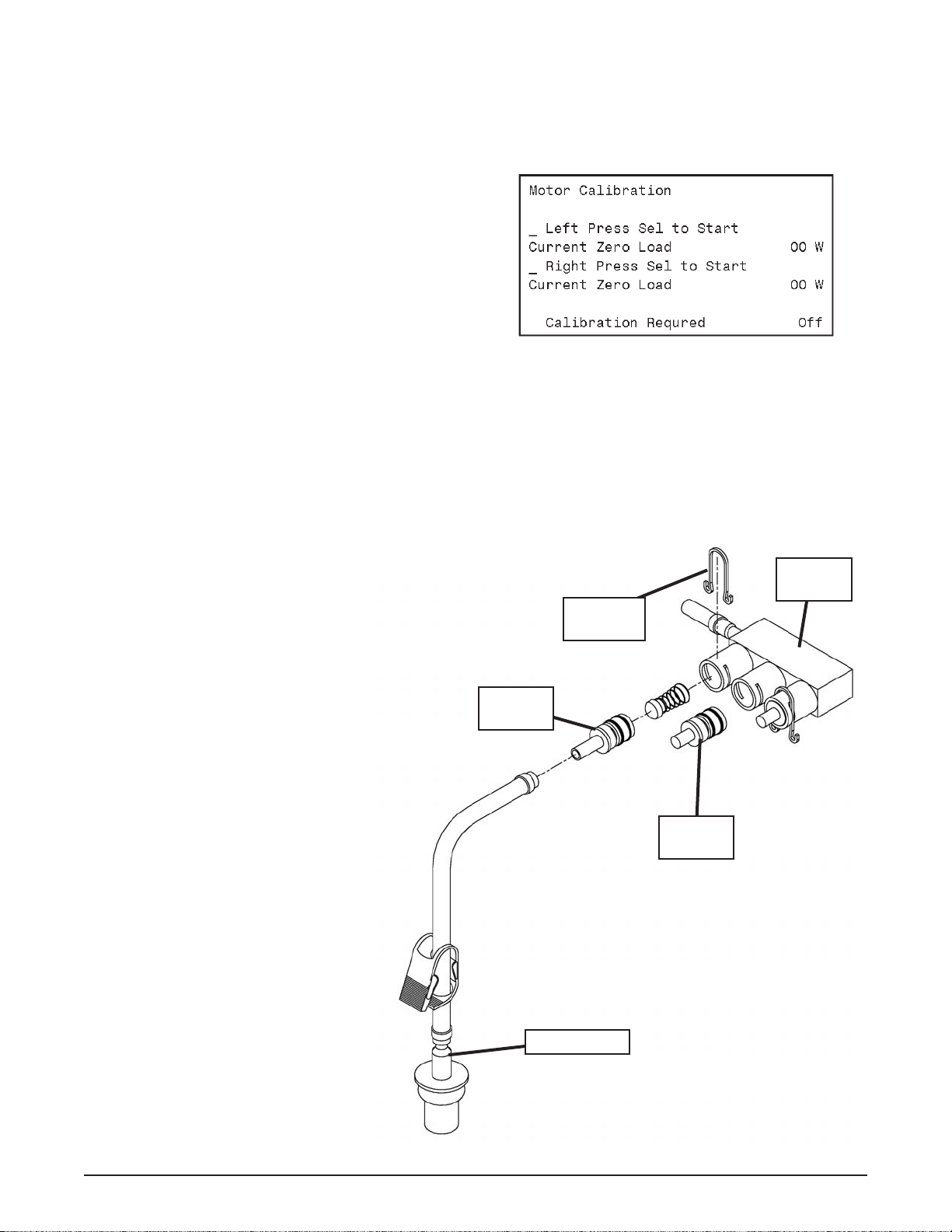
MOTOR CALIBRATION
Before starting the motor calibration, be sure there is
sanitizer in the freezing cylinder.
A. Press the On/Off Left or On/Off Right button. The
Motor Calibration screen will be displayed.
Figure 2-6
B. Move the cursor over the Left side and press the
SEL button then move the cursor over the Right
side and press the SEL button.
NOTE
The motor calibration can be done for both sides
simultaneously.
Mix Inlet
Manifold
Retaining
Clip
Manifold
Adapter
Manifold
Plug
2.6 INTELLITEC2™ SETUP
A. Disassemble, clean, lubricate
and assemble the machine
following the steps in Sections
3.3-3.7.
B. Fill the mix containers in the
cabinet with sanitizer.
C. Connect power to the machine
and press the Main Power On/
Off button.
D. Press the Pump On/Off button
when the Current Status screen
is displayed
Figure 2-5 Bag Connection System (Optional)
Owner’s Manual #513678 6 O431 I2 Model Machines
Bag Adapter
 Loading...