

Page 1

Model CC202W
OPERATORS MANUAL
Manual No. 513619 Rev.6
Page 2

Page 3

This manual provides basic information about the machine. Instructions and suggestions are
given covering its operation and care.
The illustrations and specifi cations are not binding in detail. We reserve the right to make
changes to the machine without notice, and without incurring any obligation to modify or provide new parts for machines built prior to date of change.
DO NOT ATTEMPT to operate the machine until instructions and safety precautions in this
manual are read completely and are thoroughly understood. If problems develop or questions
arise in connection with installation, operation, or servicing of the machine, contact Stoelting.
stoeltingfoodservice.com
Stoelting Foodservice Equipment
502 Highway 67
Kiel, WI 53042-1600
U.S.A.
Main Tel: 800.558.5807
Fax: 920.894.7029
Customer Service: 888.429.5920
Fax: 800.545.0662
Email: foodservice@stoelting.com
© 2014 PW Stoelting, LLC
Page 4

A Few Words About Safety
Safety Information
Read and understand the entire manual before
operating or maintaining Stoelting equipment.
This manual provides the operator with information
for the safe operation and maintenance of Stoelting
equipment. As with any machine, there are hazards
associated with their operation. For this reason safety
is emphasized throughout the manual. To highlight
specifi c safety information, the following safety defi ni-
tions are provided to assist the reader.
The purpose of safety symbols is to attract your attention to possible dangers. The safety symbols, and
their explanations, deserve your careful attention
and understanding. The safety warnings do not by
themselves eliminate any danger. The instructions
or warnings they give are not substitutes for proper
accident prevention measures.
If you need to replace a part, use genuine Stoelting
parts with the correct part number or an equivalent
part. We strongly recommend that you do not use
replacement parts of inferior quality.
Safety Alert Symbol:
This symbol Indicates danger, warning or caution.
Attention is required in order to avoid serious personal injury. The message that follows the symbol
contains important information about safety.
Signal Word:
Signal words are distinctive words used throughout
this manual that alert the reader to the existence and
relative degree of a hazard.
WARNING
The signal word “WARNING” indicates a potentially
hazardous situation, which, if not avoided, may result
in death or serious injury and equipment/property
damage.
CAUTION
The signal word “CAUTION” indicates a potentially
hazardous situation, which, if not avoided, may result
in minor or moderate injury and equipment/property
damage.
CAUTION
The signal word “CAUTION” not preceded by the
safety alert symbol indicates a potentially hazardous
situation, which, if not avoided, may result in equipment/property damage.
NOTE (or NOTICE)
The signal word “NOTICE” indicates information or
procedures that relate directly or indirectly to the
safety of personnel or equipment/property.
Page 5

SAFETY
SAFETY WARNING:
Do Not attempt to assemble or take apart any parts of the machine
without making sure the refrigeration and beater switches are in the
“OFF” position and the keys are removed. Serious bodily injury may
result.
IMPORTANT:
In order to eliminate the custard machine as a source of bacterial
contamination, it is extremely important that the following
instructions be followed exactly each time the machine is
disassembled for cleaning as part of nightly shutdown procedures.
Ross’s makes no warranties expressed or implied as to the
introduction of bacteria or other pathogens into the custard mix run
through the machine. It is beyond the scope of this manual to address
proper mix handling procedures.
WARNING:
Never use HOT
WARNING:
Refrigeration must be OFF
hopper.
water anywhere inside the machine.
when the water is present in the barrel or
Page 6
336566 or
336595
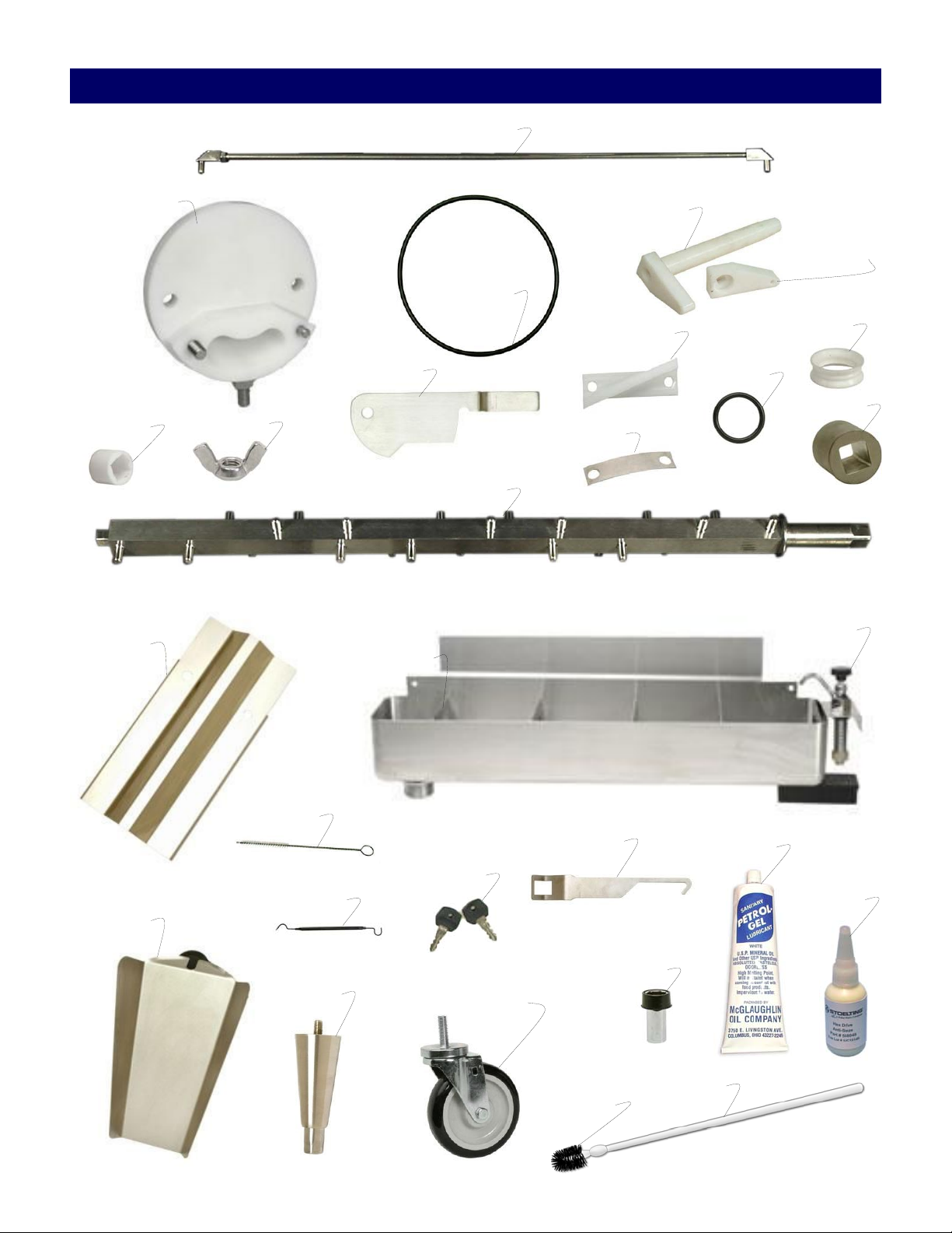
Parts
2183942
C-9000-58
C-2000-81
RG-0010
C-2000-40
C-4000-14
NT-0010
C-2000-56 or
2187993
C-4000-15
674187
C-2000-51
C-2000-50
SL-0010
RG-0020
2187605
360004-SV
C-4000-20
C-4000-19
BR-0020
C-2000-61
or 490760
C74
719102-KY
CA-0010 & CA-0020 or
244138 & 244139
C-2000-57
OF-0020-SV
BR-0030
508135
508048
BR-0035
Page 7
Parts (continued)
Standard Parts Included per Freezer
Part Description Quantity
BR-0020 Brush - Tubing (1/2") 1
BR-0030 Brush - Head (Barrel) 1
BR-0035 Brush - Handle (Barrel) 1
C 74 O-Ri ng Pi c k 1
C-2000-57 Wrench - Beater Shaft 1
C-2000-61 Leg (Ser.#0 - #28118) 2
C-4000-14 G uard Splash 1
C-4000-15 Divider (Square Dividers) 4
C-4000-19 Slide - Long (Chute) (14") 1
CA-0010 Caster - Locking (Ser.#0 - #28118) 2
CA-0020 Caster (Ser.#0 - #28118) 2
OF-0020-SV Overflow (Square Dividers) 1
244138 Caster (Ser.#28118 Plus) 2
244139 Caster - Locking (Ser.#28118 Plus) 2
360004-SV Faucet Assembly - Trough 1
490760 Leg (Ser.#28119 Plus) 4
508048 Lubricant - Spline (2 oz Squeeze Tube) 1
508135 Petrol G el - 4 oz Tube 1
Standard Parts Included per Freezing Cylinder
Part Description Quantity
BS-0020 Bushing - Shaft Support 1
C-2000-40 Bushing - Auger Shaft 1
C-2000-50 Spring 12
C-2000-51 Blade 12
C-2000-56 Gate - Front (Square Front Shaft) 1
C-2000-81 Rod - Flow Control 1
C-4000-20 Slide - Short (Chute) (10") 1
C-9000-58 Flow Control Valve Assembly (Hopper) 1
C-9000-66-SV Lid Assembly - Plastic (Includes Handle) 1
NT-00 10 Wing Nut - Sta inless Stee l 4
RG -0010 O-Ring - Front Plate 1
RG -0020 O-Ring - Rear Support Bushing 1
SL-0010 Seal - Beater Shaft 1
336566 Plate - Front (Round Front Shaft) 1
336595 Plate - Front w/Stainless Steel Insert (Square Front Shaft) 1
674187 Shaft - Beater (Square Front) 1
719102-KY Keys (#719102 Keyed Switch) 1
2183942 Flow Control Rod As sembly 1
2187109 Cover - Hopper (Stainless Steel) 1
2187605 Coupling - 1" Squar e (S tainless) 1
2187993 Gate - Front (Rounded Front Shaf t) 1
Extra Parts Included per Freezer
Part Description Quantity
C-2000-40 Wearguard - Beater Shaft (Square Front) -
C-2000-50 Spring -
C-2000-51 Blade -
RG -0010 O-Ring - Front Plate -
SL-0010 Seal - Beater Shaft -
Page 8
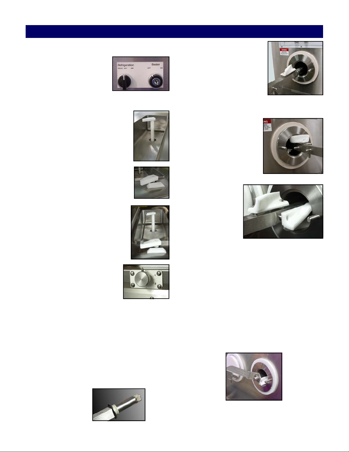
Assembly/Sanitizing
A. Initial Start
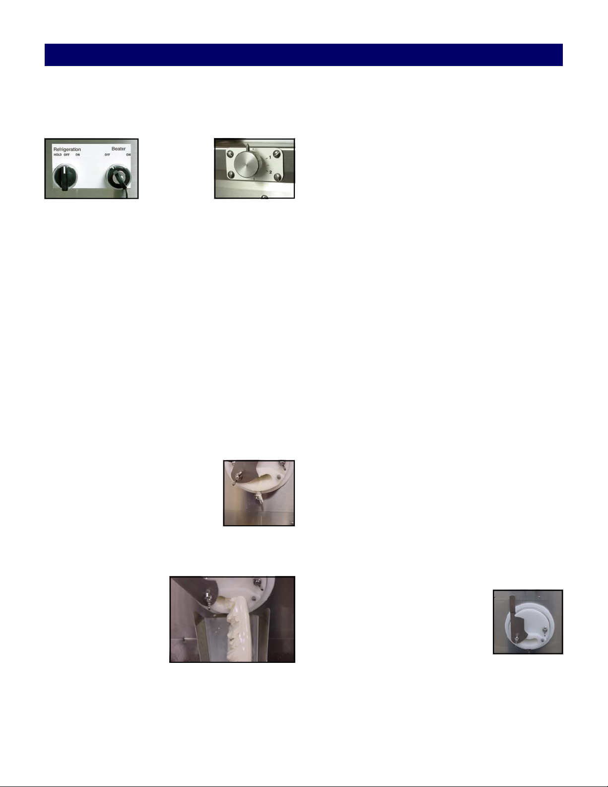
1. Make sure the refrigeration
and beater switches on the
front of the machine are
turned “OFF” and the beater
key is removed.
IMPORTANT: Wash hands and, if required, wear
disposable gloves to assemble and sanitize the machine.
B. Flow Control Valve Assem-
bly and Insertion
1. Place the white plastic flow valve in
the hopper pan drain hole. Tapered
portion of the tube to be inserted in
the drain tube hole.
2. Place the flow valve arm on the
square flow valve drive which is located at the front of the hopper pan.
3. Place one end of the flow control
rod in the small hole located on the
flow valve and place the other end
of the rod in the small hole on the
flow valve arm.
4. To adjust the flow control, turn
the flow control knob clockwise
to increase the flow and turn
counter clockwise to decrease
the flow.
C. Beater Shaft and Blade Assembly
IMPORTANT: Make sure to assemble the same
parts into the same barrel.
2. Starting on the end of the
beater shaft with the square
tip, place a metal spring
(arched upward) over the two
pins closest to the end. Place
a blade on top of the spring.
3. With the spring and blade in
place, slide the beater shaft into the barrel several
inches with the blade facing down.
4. Put a spring and blade on
the next set of pins. Push
the beater shaft further into
the barrel just far enough to
hold the blade in place on
the shaft. As you push, turn
the beater shaft so the next
set of pins is facing up.
You will have to
squeeze the blade
and spring against
the beater shaft in
order to push the
shaft into the barrel.
5. Continue adding
springs and blades to the beater shaft until all 12
blades are installed. It may get more difficult to
push the beater shaft into the barrel as you add
springs and blades.
6. Using the beater shaft wrench, push and turn the
beater shaft until it engages the drive coupling in
the back of the machine. When the beater shaft engages, it will move approximately one inch further
into the barrel. It will not be able to move back any
further. At this point, the entire shaft assembly will
be inside the barrel.
1. Place the rear gasket on the beater shaft. The gasket
should be placed over the hex cut end and pushed
over the round portion of the shaft until it bumps
against the square of the shaft. Put a small amount
of Hex Drive Anti Seize on the hex end of the beater shaft.
7. Install the large o-ring on the front plate .
Page 3
Page 9
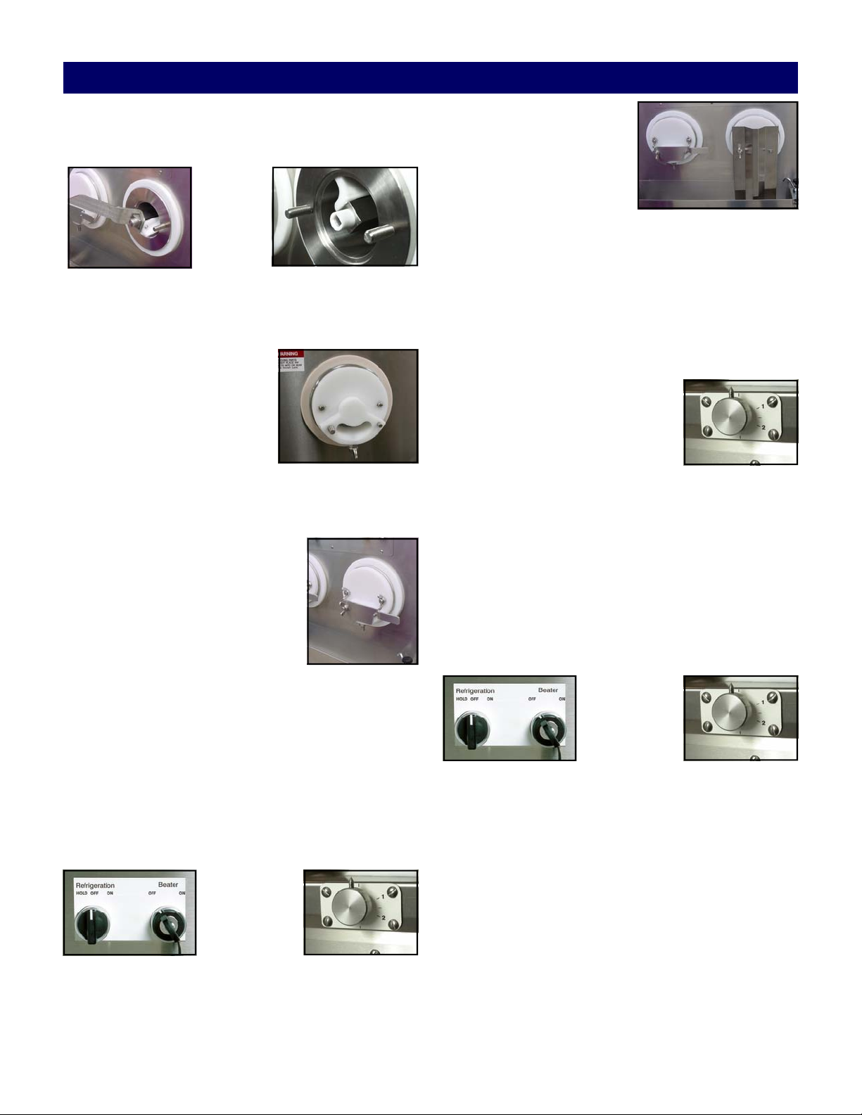
Assembly/Sanitizing
8. Put a small amount of Petrol Gel on the inside and
outside of the front bushing and install the bushing
onto the end of the beater shaft.
9. Slide the front plate over the threaded studs on the
front of the barrel with the front plate’s hole in the
bottom position. The rear of the front plate should
be tight against the front of
the barrel. If not, the beater
shaft was not installed correctly. If the front plate is
tight against the barrel, use
two wing nuts to secure It in
place. Tighten the wing nuts
securely.
10. Slide the front gate over the threaded stud so the
gate handle rests on the gate peg. If the front gate is
installed properly, it will cover
the custard outlet completely.
Secure the front gate and safety
guard with a wing nut on the
threaded stud.
11. Repeat the assembly instructions
on the remaining barrel(s).
3. Pour one to two gallons
(four to eight liters) of
approved sanitizer into
the hopper pan. The solution should be cold. Do
not exceed 100° Fahrenheit (38° Celsius).
4. Wash the sides of the hopper pan and the inside of
the hopper pan cover with a clean towel saturated
with the sanitized solution.
5. Turn the flow knob to position number “2” to allow
sanitizer to lubricate the barrel. After one or two
seconds, turn the beater switch on.
6. The sanitizer will flush through
the barrel, against the splashguard and into the dipping well.
(Note: Follow the manufacturer’s sanitizing instructions for
proper surface contact and time requirement.)
7. After all of the sanitizer has run through the barrel,
turn “OFF” the beater switch and turn the flow control to the off position. Remove the splashguard
and replace with the front gate. Close the front
gate.
8. Repeat the process on the remaining barrel(s). The
machine is now ready to operate.
D. Sanitizing
1. Put the beater key into the beater switch. Before
sanitizing, make sure the refrigeration switch on
the front of the machine is turned “OFF”; the front
control knob is to be in the “OFF” position.
2. Remove the front gate and replace with splashguard. Secure with wing nut. The splashguard directs the water into the dipping trough.
Page 4
Page 10
Machine Operation
A. System Startup
1. Verify that the flow control knob, the refrigeration,
and beater switches are in the “OFF” positions.
2. Turn on the Hopper Refrigeration.
3. Pour mix into the hopper pan. (Note: If using rerun
mix, use at least 50% fresh mix to 50% rerun mix.)
4. Turn the beater switch “ON”.
5. Turn the flow control knob to the number “1 1/2”
for approximately 3 seconds. Turn the knob back to
the “OFF” position. This allows custard to mix to
flush the sanitizer from the barrel to avoid instant
freezing of the sanitizer in the barrel.
Note: If a “growling” noise comes from the machine
during this procedure, it may be an indication that
there is not enough mix entering the barrel. Increase the flow slightly by adjusting the flow control
knob on the front of the machine. Keep in mind that
there are several minutes lag time between the increased mix flow and the elimination of any
“growling” noises.
11. Continue to run the mix into the bucket until it
reaches the desired quantity.
B. Hold Cycle During Operation
1. Adjust the flow control knob to the “OFF” position.
Wait approximately 1 minute.
2. Turn the refrigeration switch to the “Hold”.
3. When the frozen custard stops flowing, turn the
beater switch to the “OFF” position and REMOVE
KEY. Note: This should take approximately 2 minutes.
6. Place the custard slide on the threaded stud beneath
the front plate and secure firmly with a wing nut.
Aim the custard slide into a dipping cabinet or
other suitable container for dipping.
7. Open the front gate.
8. Within several seconds, a few
ounces of liquid mix and sanitizer
will flow out of the custard outlet
and into the dipping well. Discard
this mix.
9. Turn the refrigeration switch on and wait approximately 2 minutes for a chatter noise.
10. Set the flow control
know to “1/2-1” position until frozen custard is seen at the custard outlet. Increase
the mix by turning the
flow control knob to
gain the desired custard texture.
4. Clean out excess frozen custard from the custard
outlet on the front plate to prevent dripping.
5. Replace key.
6. Close the front gate.
7. Remove custard slide.
C. Resuming Production During Operation
1. Turn the beater switch “ON”.
2. Turn the refrigeration switch “ON”.
3. Wait for a chatter noise, approximately 1 minute.
Turn the flow control knob to the number “1-1 1/2”
position.
4. Open the front gate completely.
5. When the custard appears, adjust
the flow control knob to gain the
desired custard texture.
6. Continue to run the mix into the dipping cabinet
until you have the amount that you need.
Page 5
Page 11

Machine Operation
D. Preparing for Shutdown (hopper empty)
Removal of Remaining Custard in the Barrel when no
mix is in the Hopper
1. Turn refrigeration switch to “Off”
2. Let machine rest for approx. 20 minutes. This allows the barrel enough time to warm before removing remaining custard.
3. Turn the beater switch is “ON”.
4. Run remaining custard through the barrel.
5. Turn the beater switch to “OFF” position.
6. Close the front gate and remove the custard slide.
E. Preparing for Shutdown (mix in hopper)
Removal of Remaining Custard in the Barrel when mix
is still in the Hopper
1. Turn “OFF” the refrigeration switch.
2. Let machine rest for approx. 20 minutes. This allows the barrel enough time to warm before draining the remaining mix from the hopper.
3. Take a sanitized bucket and place it at the opening
of the front plate.
4. Turn the flow control to “4”. This allows the mix to
drain into the barrel and then to your sanitized
bucket.
IMPORTANT: In order to eliminate the custard
machine as a source of bacterial contamination, it is
extremely important that the following instructions
be followed exactly each time the machine is disassembled for cleaning as part of nightly shutdown
procedures. Ross’s makes no warranties expressed
or implied as to the introduction of bacteria or other
pathogens into the custard mix run through the machine. It is beyond the scope of this manual to address proper mix handling procedures.
Page 6
Page 12
Cleaning and Disassembly
A. Cleaning
1. Remove the front gate and install the splashguard.
2. Make a cleaning solution of 1½ to 2 gallons (4-8
liters) of cold water and the correct amount of
cleaning solution. Do not exceed 100 degrees Fahrenheit (38 degrees Celsius).
3. Pour the cleaning solution into the hopper pan.
Wash down the sides and bottom of the hopper pan
to dilute remaining mix.
4. Turn the flow control valve to the number “2” position to allow sanitizer into the barrel.
5. Turn the beater switch to “ON” and run the cleaning solution through the barrel.
Make sure the refrigeration switch is in the “OFF”
position.
6. Repeat the procedure until all mix residue is gone
and the hopper pan is clean.
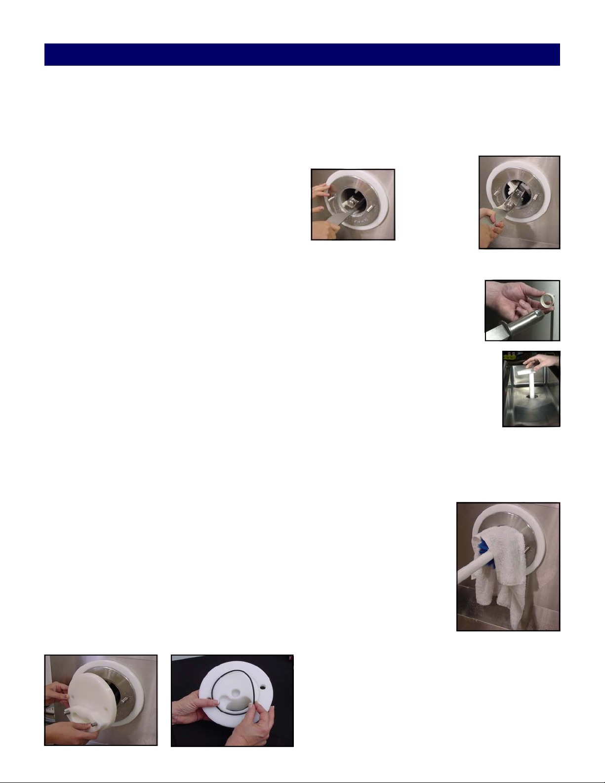
3. Lay the washed parts out on a sanitized counter for
air drying. With the beater shaft wrench, pull the
beater shaft partially out of the barrel by grabbing
behind the first blade. Continue to pull the beater
shaft forward and remove each blade and spring
and place in a container for cleaning.
CAUTION: Be careful not to scratch the inside of
the barrel with the beater shaft.
4. Remove the Rear Gasket and
wipe the lubricant off the hex end
of the beater with a clean towel.
5. Remove the flow control rod and
the flow control valve assembly.
7. Turn the beater switch to the “OFF” position and
remove the key.
8. Properly dispose of the cleaning solution.
SAFETY WARNING: Do not attempt to remove the
front plate, or beater shaft without first removing
the key from the beater switch. Serious bodily injury may result.
B. Disassembly
IMPORTANT: Make sure to keep the parts for
each individual barrel separated. The parts need to
be installed into the same barrel every time the machine is disassembled.
1. Remove key
2. Remove the front gate and front plate for washing.
Remove the o-ring from the front plate. Remove
front bushing from beater shaft.
6. Take all parts to the cleaning area for
washing. Add sufficient hot water and
cleaning solution to cover all of the
parts. Let soak for five minutes. Make
sure mix is removed from all small, hard to clean
areas of the parts, including o-ring grooves.
7. While the parts are soaking, use a cleaning solution
and barrel brush to clean inside barrel.
8. Wrap a clean towel soaked
with cleaning solution
around a barrel brush and
run the brush and towel
through the barrel until it is
clean.
Page 7
Page 13

Cleaning and Disassembly
9. Make sure to clean
the drip pan that is
located at the rear of
the machine in the
access panel. Clean
out any custard in
the pan.
10. Clean the front mounting plates with a towel.
11. Clean the sheet metal on the entire machine. Use
stainless cleaner and polish on the sheet metal to
maintain the machine’s appearance. Do not use
stainless cleaner on areas where mix or frozen custard is used.
12. Return to the sink and wash each part. Place in a
rinse tank and then a sanitizing tank with a proper
dilution of an approved sanitizer.
IMPORTANT: Failure to follow these cleaning
procedures exactly, each and every night, may
result in eventual bacterial contamination of the
frozen custard product and health and legal
problems for the purchaser of this equipment
and the restaurant patrons
NEVER USE
HOT WATER ANYWHERE
INSIDE THE MACHINE!
502 Highway 67
Kiel, WI 53042
Phone: 800-558-5807
Fax: 920-894-7029
www.frozencustard.com
www.stoelting.com
Page 8
Page 14

Page 15

ROSS & TELME WARRANTY
1. Scope:
Stoelting, LLC warrants to the first user (the “Buyer”) that the freezing cylinders, hoppers,
compressors, drive motors, speed reducers, beaters and agitator of Stoelting Ross and Telme product
line will be free from defects in materials and workmanship under normal use and proper maintenance
appearing within two (2) years, and that all other components of such equipment manufactured by
Stoelting will be free from defects in material and workmanship under normal use and proper
maintenance appearing within twelve (12) months after the date that such equipment is originally
installed.
2. Disclaimer of Other Warranties
THIS WARRANTY IS EXCLUSIVE; AND STOELTING HEREBY DISCLAIMS ANY
IMPLIED WARRANTY OF MERCHANTABILITY OR FITNESS FOR PARTICULAR
PURPOSE.
3. Remedies
:
Stoelting’s sole obligations, and Buyer’s sole remedies, for any breach of this warranty shall be the
repair or (at Stoelting’s option) replacement of the affected component at Stoelting’s plant in Kiel,
Wisconsin, or (again, at Stoelting’s option) refund of the purchase price of the affected equipment,
and, during the first twelve (12) months of the warranty period, deinstallation/reinstallation of the
affected component from/into the equipment. Those obligations/remedies are subject to the conditions
that Buyer (a) signs and returns to Stoelting, upon installation, the Checklist/Warranty Registration
Card for the affected equipment, (b) gives Stoelting prompt written notice of any claimed breach of
warranty within the applicable warranty period, and (c) delivers the affected equipment to Stoelting or
its designated service location, in its original packaging/crating, also within that period. Buyer shall
bear the cost and risk of shipping to and from Stoelting’s plant or designated service location.
4. Exclusions and Limitations
This warranty does not extend to parts, sometimes called “wear parts”, which are generally expected
to deteriorate and to require replacement as equipment is used, including as examples but not
intended to be limited to o-rings, auger seals, auger support bushings and drive belts. All such parts
are sold
Further, Stoelting shall not be responsible to provide any remedy under this warranty with respect to
any component that fails by reason of negligence, abnormal use, misuse or abuse, use with parts or
equipment not manufactured or supplied by Stoelting, or damage in transit.
THE REMEDIES SET FORTH IN THIS WARRANTY SHALL BE THE SOLE LIABILITY
STOELTING AND THE EXCLUSIVE REMEDY OF BUYER WITH RESPECT TO
EQUIPMENT SUPPLIED BY STOELTING; AND IN NO EVENT SHALL STOELTING BE
LIABLE FOR ANY INCIDENTAL OR CONSEQUENTIAL DAMAGES, WHETHER FOR
BREACH OF WARRANTY OR OTHER CONTRACT BREACH, NEGLIGENCE OR
OTHER TORT, OR ON ANY STRICT LIABILITY THEORY.
:
:
AS IS.
Form 721-053, Rev.01
Page 1 of 1
September 1, 2007
Page 16

001.1332808.2
Page 17

Installation Guide
Step 1 Running Line Sets:
* If the freezer is water-cooled, proceed to Step 2 Running Electrical Connections.
* Line sets are not supplied with the freezer.
* The lines sets can be installed prior to receiving the custard freezer.
1) An air-cooled freezer requires a remote condensing unit and line set for each freezing cylinder
line sets must be 3/8” for the liquid line and 7/8” for the suction line (The M202 suction line needs
5/8”). When running the line sets, each 10’ of vertical rise, install a p-trap in the suction line. For every
horizontal line set run, pitch the suction line towards the compressor to assist with oil returning back to
the compressor.
2) After the line set is installed, perform a thorough leak test. Malfunctions of the equipment due to
leaks in the line set are not covered by the Stoelting/Ross warranty.
3) Insulate the suction line with a minimum of 3/8” wall thickness or the wall thickness required by local
code. In humid areas, use thicker insulation. In areas that are exposed to extreme temperatures, insulate
the liquid line to prevent excessive sub cooling or heating of the liquid refrigerant. Fasten all lines
securely along ceilings, walls and roofs. Avoid creating any type of kink in the lines. The Stoelting/Ross
warranty does not cover malfunctions or capacity issues with equipment caused by kinks in the line sets.
4) Use good piping practices when installing line sets. Seal the ends of the line sets during installation to
prevent exposure to the atmosphere and foreign objects. Blow the lines out with dry nitrogen to remove
any debris that might be in the line sets. When running line sets through a wall or roof, mark the lines to
eliminate confusion as to which line set is running to which cylinder.
Example: Mark the liquid and suction lines with the respective cylinder number. Facing the front of the
freezer, cylinders are numbered left to right.
5) When brazing the joints, purge dry nitrogen through the lines to minimize oxidation of copper inside
of the lines. The Stoelting/Ross warranty does not cover problems with the refrigeration system that are
caused by oxidized material in the lines.
Step 2 Running Electrical Connections:
1) The freezer requires a separate electrical connection for each freezing cylinder. Refer to the
nameplate on the freezer for proper electrical supply. Each freezing cylinder has its own electrical
system and condenser so if one cylinder fails, the other cylinder will still be operational.
*An air-cooled freezer needs two circuits for each freezing cylinder, one for the remote condensing unit
and one for the freezing cylinder.
*A water-cooled freezer needs one circuit for each freezing cylinder.
2) The electrical boxes are located behind the lower front panel. Labels indicate which cylinder each
electrical box powers. No pigtails are supplied with the freezer or condensing unit.
3) If the condensing unit is on the roof or ground, a quick disconnect box needs to be installed to provide
power.
. The
Page 18

4) Do not turn on the power to the freezer or the condensing unit until the refrigeration lines have been
connected and the system has been charged with refrigerant. Label the circuit breakers with information
regarding which cylinder and condensing unit the breaker is designated for to prevent confusion if
power ever needs to be shut off.
5) When connecting power to the freezer, run the line under the freezer and through the bottom of the
electrical box. Remove the electrical box cover by loosening the four screws. The screws do not have to
be removed. Connect the power to the 4-circuit terminal strip. The 4-circuit terminal strip is labeled L1,
L2, L3, and GND. After connections are made, place the cover on the electrical box, but do not tighten
the cover (for single-phase freezers the cover can be tightened). The electrical box may need to be
accessed when checking for proper rotation of the motor.
Step 3 Plumbing Connections:
1) On water-cooled freezers, the water inlet is a standard garden hose connection and the water outlet is
5/8” OD copper tubing. The connections are located at the back of the freezer. Remove the rear panel to
access the connections. Run the plumbing under the freezer frame. Water-cooled freezers use
approximately 3 gallons of 75°F water per minute while in use (the M202 uses 2 gallons per minute).
The freezer does not use any water when not in use.
2) The freezer is equipped with a dipping trough that requires a water inlet line and a drain line. The
water inlet has a 5/16” OD brass female connector (the M202 female connector is 1/4” OD). Solder a
5/16” line to the water valve inlet using silver solder (the M202 requires a 1/4” line). Install a shutoff
valve in the water inlet line. The drain connection is 1-1/2”. Run a drain line from the trough to a drain
on the floor. Leave enough slack in the drain line so that the lower front panel can be easily removed for
service.
3) If the freezer is equipped with the hopper faucet option, run the hopper faucet tubing to the dipping
trough inlet and install a T. This will supply water needed for the hopper faucet and the water valve for
the dipping trough.
Step 4 Receiving and Installing Remote Condensing Units:
* The remote condensing units may be sent prior to delivery of the freezer.
* The freezer requires one remote condensing unit per cylinder.
1) Upon arrival, check the entire remote condenser units for any damage that may have occurred during
transit. With the method of packaging used, the remote condensers should arrive in excellent condition.
The carrier is responsible for all damage in transit, whether visible or concealed. Do not pay the
freight bill until the remote condenser units have been checked for damage. Have the carrier note any
visible damage on the freight bill. If concealed damage or a shortage is found later, advise the carrier
within 10 days and request inspection. The customer must place a claim for damages and/or shortages in
shipment with the carrier. Stoelting cannot make any claims against the carrier.
2) Remove cardboard covering off the condensing units.
3) Place the condensing units in their predetermined location, either on the roof or on the ground. A
crane or forklift will be needed if the units will be placed on a roof. The condensing units weigh
approximately 200 lbs. each.
Page 19

4) Using ratchet with a 1/2” socket, remove the two lag bolts that secure the condensing unit to the
pallet.
5) Place the condensing units on 4” x 4” treated wood or similar material so that the units are not sitting
directly on the ground or the roof. Secure the condensing units to the 4” x 4” using lag bolts. Adhere to
all local, state, and federal codes governing this type of installation. Some areas have specific
“hurricane-proof” requirements for roof installations. Allow at least 2 feet of clearance on the air intake
and discharge sides of the condensers. Do not set the condensers so that one is blowing air directly into
the other condensing unit. The ideal set up is to have all the condensing units set in a row. See example
diagram.
Example:
Remote air-cooled Condensers typical install.
Direction of airflow viewed from top down.
6) Use an Allen wrench to open the shut off valves and release some of the nitrogen charge in the
condensing unit. The shut off valves are located on the outside of the condensing unit. If no nitrogen is
present then the unit needs to be leak checked prior to connecting the refrigeration lines.
7) Braze the suction line and liquid line from the line sets to the condensing unit. When brazing, wrap
the shut off valve with a cold wet rag and make sure that the valve is fully open. If valve is not wrapped,
damage to the valve may result. When installing the suction line, angle it towards the condensing unit so
that oil can flow back towards the compressor.
8) Use good piping practices. Keep pipes as clean as possible. Do not let any debris or copper shavings
get inside system otherwise the refrigeration valves may not work properly.
Page 20

Step 5 Receiving the Custard Freezer:
1) Upon arrival, check the entire freezer for any damage that may have occurred during transit. With the
method of packaging used, the freezer should arrive in excellent condition. The carrier is responsible
for all damage in transit, whether visible or concealed. Do not pay the freight bill until the freezer has
been checked for damage. Have the carrier note any visible damage on the freight bill. If concealed
damage or a shortage is found later, advise the carrier within 10 days and request inspection. The
customer must place a claim for damages and/or shortages in shipment with the carrier. Stoelting cannot
make any claims against the carrier.
2) Remove the top of the crate using a hammer or pry bar.
3) Remove the eight lag bolts from the freezer using a 1/2” ratchet. Remove the front and rear crate
walls.
4) Remove the four lag bolts located inside the left and right crate walls using 1/2” ratchet. Remove the
left and right crate walls.
5) Remove the plastic wrapping on the freezer. Remove the lower front and back panel on the freezer.
6) Remove the four lag bolts located inside freezer on the frame with a 9/16” ratchet. Remove the two
lag bolts that hold the skid together with a 9/16” socket.
7) If the freezer has the shipping casters or if it is water-cooled, the casters will be in a box located in the
hopper pan. A set of casters includes two casters with locks and two casters without locks. Screw the
casters into the threaded holes and tighten them using a pair of channel locks. After installing the
casters, knock out bottom 4” x 4” of the freezer skid.
* If the freezer does not come with casters, install the stainless steel legs. The legs are located in the
hopper pan on top of the freezer. After installing the legs, use a pallet jack to move freezer into place.
8) Put front and back panels on the freezer.
Step 6 Setting In Place and Making Freezer Connections:
1) Roll the freezer into the desired location. Leave adequate space around the freezer for the removal of
service panels. Remove the left, right, back and lower front service panels.
* After the refrigeration lines are connected, air-cooled freezers cannot be moved.
2) Use a pallet jack or floor jack to lift the front of the freezer, remove the two shipping casters with a
pair of channel locks, and install the stainless steel legs. Make sure the legs are adjusted all the way in,
and screw two of the legs into the frame. Secure them tightly using channel locks. Repeat with the back
of the freezer.
* If the freezer is water-cooled, casters are standard with freezer.
3) Accurate leveling is necessary to ensure proper operation. Place a bubble level on top of the freezer at
each corner to check for level condition. If adjustment is necessary, level the freezer by turning the
bottom part of each leg or caster in or out.
Page 21

To finish installing a water-cooled freezer, proceed to Step 7 Running product and setting pressures
for the custard freezer.
4) Connect the refrigeration lines from the line sets to the freezer. Access the freezer from the left or
right service panel. The refrigeration system has a charge of dry nitrogen. Use caution when connecting
the lines. Connect the suction line first then connect the liquid line. Run the refrigeration lines under the
freezer. There is approximately 6” of clearance between freezer and the floor. The stainless steel legs are
adjustable and can raise the freezer up to 7” off the floor if necessary. Wrap the suction solenoid in a
cold wet rag when soldering to prevent damage to the solenoid. Also, be aware of the electrical conduit
inside custard freezer while soldering the refrigeration lines. A liquid line dryer is supplied with the
freezer and should be the last connection made in the system. Use good piping techniques to keep the
system clean. Do not leave the lines open and exposed for a long period.
5) After finishing the refrigeration connections, connect power to the freezer. Refer to Step 2 Running
Electrical Lines for the proper procedures. Check the rotation of the beater shaft. When looking at the
freezer from the front, the shaft needs to turn counterclockwise. If the shaft is turning the wrong
direction on a three phase freezer, shut off power to the cylinder and switch the L1 and L3 wires. Check
rotation again to verify the shaft is rotating counterclockwise. Once verified, tighten the screws on the
electrical box cover. *If the freezer is single phase and the beater shaft rotation is clockwise, then
complete one of the following procedures. Check rotation after each procedure.
A) Change programming on variable speed drive to reverse motor.
B) Change the T1 and T3 output leads going to the motor from the drive.
C) Change the leads inside the motor electrical box.
6) Check the refrigeration systems for leaks. When pressurizing the system, turn the refrigeration switch
to hold position to energize the suction solenoid. Also, make sure that the shut off valves are open on the
remote condensing unit. Check the refrigeration system with 300 psi of nitrogen. Make sure the system
will hold the pressure for a minimum of 2 hours.
7) After the leak check, connect a vacuum pump to the system and evacuate it to 500 microns for a
minimum of 1 hour. Make sure the suction solenoid and the shut off valves on the condensing unit are
opened. Perform a standing vacuum test. If the vacuum deteriorates and continues to rise there is a leak.
Find it, repair it, and repeat the evacuation procedure until the freezer passes a standing vacuum test.
While the refrigeration system is under a vacuum, insulate the suction line. Insulation is needed up to the
shut off valve on the condensing unit. Use 3/8” tube insulation or insulation required by local code.
8) Use good refrigeration practices to charge the system with the required charge (see below). Make sure
the suction solenoid is energized and that the shut off valves are open.
Air-Cooled
Model Hopper Charge
CC101 16 oz of R-134a 24 lbs of R-404a 10 lbs of R-404a
CC202 18 oz of R-134a 24 lbs of R-404a 10 lbs of R-404a
CC303 19 oz of R-134a 24 lbs of R-404a 10 lbs of R-404a
CC404 20 oz of R-134a 24 lbs of R-404a 10 lbs of R-404a
M202 N/A 20 lbs of R-404a 8 lbs of R-404a
Charge per cylinder
Water-Cooled
Charge per cylinder
*Air-cooled freezers do not ship with refrigerant and require refrigerant to be supplied on site. Watercooled freezers are factory charged. The hoppers for air-cooled and water-cooled freezers are factory
charged.
*The charge for air-cooled freezers is sufficient for up to a 50 ft. line set. If the line set is longer, add 1
lb. of refrigerant for every 10 ft. of additional line (up to 150 ft. total).
Page 22

Step 7 Running product and setting pressures for the custard freezer:
* Complete the Custard Freezer Start-Up and Training Checklist located with the spare parts kit or
in the back of this manual and send it to Stoelting.
1) Remove all spare parts from the hopper before running product. Unwrap the parts and check for
damage. Refer to the list in the manual to make sure no parts are missing. The cylinders need to be under
a load to set the pressures. If custard is not available, run the machine for two minutes and check for
frost in the freezing cylinder. This will indicate that the refrigeration is functioning.
2) Disassemble, clean and sanitize each freezing cylinder. Refer to the manual for proper instructions.
3) After assembling and sanitizing the freezer, add custard mix to the hopper. Follow the instructions in
the manual to start freezing the custard (run one cylinder at a time to set the pressures). Connect gauges
to the suction line and the discharge line. When product starts coming out of the faceplate, locate the low
pressure gauge on the front of the freezer and set the AXV to 30 psi. Remove the white plastic cap from
the AXV and turn the valve counterclockwise to decrease the pressure or clockwise to increase the
pressure. Turn the valve 1/4 turn at a time and wait at least 1 minute before making another adjustment.
Connect a gauge to the suction line at the compressor and make sure the pressure is 25 psi. Adjust the
crankcase pressure regulator (CPR) if the pressure is not correct. Remove threaded brass cap on the front
of the CPR and adjust the valve with a 5/16” Allen wrench. Connect a gauge to the suction line at the
hopper and adjust the hopper AXV to 55 psi.
4) Check the faceplate to see if the custard is at the desired texture and temperature. The standard
normal serving temperature of frozen custard coming out of the freezer is 18°-22°F.
5) Set the pressures for the remaining cylinders.
* If the freezer is water-cooled, the discharge pressure was already set at the factory. Run custard mix
through the freezer to double-check and fine-tune the discharge pressure for the particular mix being
used.
* The remote condenser unit has a head pressure control set for a minimum of 255 psi.
* Chocolate and vanilla mixes run differently. Usually the pressures in the chocolate cylinder will need
to be set slightly lower than the pressures in the vanilla cylinder. Custard mixes that use an extract
flavoring will also run differently. Try different pressure settings by adjusting the AXV. Adjust the
pressure setting between 28-32 psi (the freezer will not operate correctly if the AXV is set lower than 28
psi).
6) If the freezer is equipped with the lemon ice option, set the lemon ice AXV. The lemon ice option is
designated for one cylinder (right cylinder). With the system still running product, turn the lemon ice
switch on. The AXV is located behind the cylinder in front of the freezer. Set the lemon ice AXV for 40
psi.
7) When testing is done, take the cylinders apart and clean the custard freezer. Refer to operations
manual under shutdown and disassembly.
Page 23

Trouble Shooting Guide for the Ross
Frozen Custard Machine and Dipping Cabinet
Ross Custard Machine Problem and Possible Solutions
Custard is running to cold or Blades chatter during running:
1) First increase the flow; machine needs to run for at least a minute before you see a
change in the product. Average flow setting while running custard is 1.5 to 2.
2) Hopper pan is low or out of mix.
3) Check to see if flow valve is plugged.
4) The refrigeration system for that barrel set to cold for the mix. Call Ross service
department and we can help over the phone to adjust setting properly.
5) Check the belts on the motor to make sure they are not loose and slipping.
6) Blades may be worn. The blades need to be replaced annually.
Custard is running too soft:
1) First decrease the flow setting; machine needs to run for at least a minute before you
see a change in the product. Decrease flow setting until you reach the desired texture.
Average flow setting while running custard is 1.5 to 2.
2) Check to see if the flow valve is plugged.
3) No electrical power to the refrigeration condensing unit, need to check the main
breaker for the condensing unit.
4) The refrigeration system for that barrel is set to warm for the mix. Contact Ross
service department and a technician can help adjust system properly.
5) Condenser on remote unit is blocked and will need to be cleaned out.
6) For water-cooled models check to make sure that water was not shut off to the
machine.
7) Refrigeration system not functioning correctly.
Beater freezes up in the hold cycle:
1) Custard was not cleared out of barrel when going from run mode to the hold cycle
mode.
2) Motor needs to remain on when turning refrigeration switch from run to hold for at
least 2 minutes before shutting the motor off otherwise the barrel will freeze up in the
hold cycle.
3) Ranco temperature control (located on your service side on machine) is set to cold for
the hold cycle; refer to the operating manual for proper settings.
4) Refrigeration system not functioning correctly.
Hold cycle not running:
1) Make sure the refrigeration switch is on the hold cycle mode.
2) Ranco temperature control (located on your service side on the machine) is set to
warm. Need to refer to the operating manual for the proper setting.
3) Main circuit breaker for the refrigeration unit is tripped and needs to be reset.
4) Check that the electrical plug for that barrel is still plugged in to the outlet on the wall.
Page 24

5) Condenser for remote unit is blocked and needs to be cleared.
6) For water-cooled machines check that the water supply was not turned off to the
machine.
7) Refrigeration system not functioning correctly.
Beater motor freezes up in the run mode:
1) Hopper pan is out of mix.
2) Check that flow valve is not plugged.
3) Running the flow setting to low and need to increase the flow setting.
4) Check the belts to make sure they are not loose and slipping. Tighten if necessary.
5) Do not shut motor off while running custard. Barrel will freeze up instantly.
6) Refer to Custard is running to cold section in this trouble shooting guide.
Beater motor does not function:
1) Push the beater motor reset button located on your service side on the machine.
2) Check that machine is not unplugged from the outlet on the wall.
3) Main circuit breaker for that barrel is tripped and needs to be reset.
Custard stored in hopper is too cold:
1) Ranco temperature control (located on the service side on the machine) is set to cold.
Refer to the operating manual for proper settings.
2) Refrigeration system is not functioning correctly.
Custard stored in hopper is too warm:
1) Make sure the hopper switch is on.
2) Ranco temperature control (located on the service side of the machine) is set to warm.
Refer to the operating manual for proper settings.
3) If there is no display on the Ranco temperature control then need to check that hopper
is plugged into the wall outlet. If plug is ok then need to check the main breaker for the
outlet on the wall and reset if tripped.
4) Check condenser coil on the hopper-condensing unit (located inside machine under the
beater motors) and clean with a soft brush or condenser coil cleaner if there is dust. After
cleaning let run for 1 hour to see if temperature drops on thermostat.
4) Refrigeration system not functioning correctly.
Ross Dipping Cabinet Problem and Possible Solutions
Custard stored in cabinet too cold:
1) Ross Manufacturing recommends running enough custard to cover a 2-hour period.
Custard stored in cabinet longer than 2 hours has a tendency to become to firm in the
cabinet.
2) Refer to the operating manual for proper temperature settings. The Ranco temperature
control will be located on some models in the front; on other models it will be located on
the back of the cabinet. Allow at least 1 hour before you will see any change in the
product and temperature.
3) Refrigeration system not functioning correctly.
Page 25

Custard stored in cabinet too warm:
1) Refer to operating manual for proper temperature settings. After adjusting temperature
allow cabinet to run for 1 hour before any change in product or temperature.
2) If light is not on when switch is on then need to check that dipping cabinet is still
plugged into outlet. If it is need to check main breaker for that particular outlet and reset
if tripped.
3) Check condenser coil (located inside cabinet, need to remove front or rear panel to
access) for dust build up. If dust is present use a soft brush or condenser coil cleaner and
remove dust build up. After cleaning condenser allow cabinet to run for 1 hour before
you will see any change in the product or temperature change on the display.
Dipping Cabinet not cooling at all:
1) Check and see if light is on by the switch. If no light on check that unit is plugged into
the wall and check that cord is not cut. Also need to check that the breaker for that outlet
has not tripped. If the breaker has tripped then reset and check dipping cabinet if it is
running.
2) Check condenser coil and make sure not plugged with dust, if it is need to clean and
try running again.
3) Refrigeration system not functioning correctly and need to contact service technician
at Ross Manufacturing for assistance.
*This is just a guideline to help you reduce the down time of the machine and for
having to try and schedule a service technician to look at your machine. If you need
any assistance with the machine after following this guideline call Ross
manufacturing and speak with a service technician before calling a local
refrigeration company. The Ross service technician will be able to help you further
and whether or not you need to have a local technician look at the machine. Ross
Manufacturing can be reached at our toll free # 1-888-339-4429, for after hour or
weekends a service technician can be reached by calling the toll free number, the
answering machine will direct you to a number of the service technician’s on call.
Revised 4-16-04
Page 26

Page 27

Typical Machine Settings
Note: Please use these settings as guidelines. Each machine may vary and should be set up for
highest efficiency, best quality, and preferred product texture. Space has been provided for
inputting the final settings after set up
Hopper Temperature Control
(Location within machine)
Note: Temperature settings may be adjusted
for your particular requirements.
Ranco ETC 111000- One stage controller:
Factory Settings
F/C: F ________
Temp: 38 ________
Diff: 1 degree ________
Mode: CL ________
Hold Cycle Temperature Control
(Location within Machinery Electrical Box)
Note: Temperature setting may be adjusted
for your particular settings.
Option #1
Ranco ETC 2110002 2-stage controller)
Stage #1
Factory Settings
F/C: F _______ F/C: F _______
Temp: 0 _______ Temp: 38 _______
Diff 1: 1 degree _______ Diff 1: 1 degree _______
Mode: C1 _______ Mode: C2 _______
Option #1
Ranco ETC 2110002 2-stage controller)
Stage #1
Factory Settings
F/C: F _______
Temp: 38 _______
Diff 1: 1 degree _______
Mode: C1 _______
(If your unit is equipped with
Stage #2
(If your unit is equipped with
Your Settings
Your Settings Factory Settings Your Settings
Your Settings
Page 28

Barrel Expansion Valve Adjustment
(Location within Machinery Section)
Note: Each machine and mix formulation have differing freezing points Therefore each machine must be
adjusted for a particular mix. You may adjust each automatic expansion valve for your own particular
setting and desired firmness.
Automatic Expansion Valve: Original Factory Setting 25 PSIG
Typical pressure setting for most custard mixes
: 32 PSIG
Your final valve ________
Note: each machine will differ slightly in preferred setting.
Condensing Unit Settings: Water Cooled Units
(Location on each condensing unit)
Water Regulator: Adjusted at 235 PSIG
High Pressure Safety Cut-Out: Non-Adjustable at Approx. 350 PSIG
Low Pressure Safety Cut-Out: Cut-In 20 PSIG
Cut-Out 5 PSIG
Crankcase Pressure Regulator 27 PSIG
Page 29

PREVENTATIVE MAINTENANCE
Stoelting recommends following this preventative maintenance schedule to keep the freezer clean and operating
properly.
WEEKLY
CLEAN INSIDE OF FREEZER
Remove all side panels and clean the inside of the freezer. Wipe any custard that may have dripped onto
the inner panels with a damp soapy towel. Wash the drain tray.
CLEAN REAR SHAFT SUPPORT BUSHING
Remove the rear support bushing by unscrewing it. Remove the o-ring and examine it. Replace the o-ring
if it is cracked or worn. Wash the bushing and lubricate the o-ring with Petrol-Gel.
CHECK FOR SHAFT ALIGNMENT
It is important to keep the auger shaft aligned at all times. There are a few early indications that the shaft
is out of alignment. Make sure there are no metal shavings under the bearing. Inspect the rear coupli ng
for wear. Check the front door plate for wear from the front bushing. If the shaft is out of alignment, the
freezer may be making a lot of noise.
Contact Stoelting Customer Service for an alignment kit if you suspect that the auger shaft is out of
alignment.
QUARTERLY
REPLACE BARREL PARTS
Follow the Parts Replacement Schedule to keep the freezer operating properly.
CLEAN CONDENSER COILS (AND FILTERS IF APPLICABLE)
The coils on the hopper, dipping cabinet and remote condenser need to be cleaned to ensure proper
airflow. Use compressed air to clean the condensers. Blow the air in the opposite dire ction of the normal
airflow. If the condenser has a filter, remove it and vacuum or brush clean. Rinse the filter with clean
water and allow it to dry before replacing it on the condenser.
ANNUALLY
REPLACE BARREL PARTS ACCORDING TO REPLACEMENT SCHEDULE
Follow the Parts Replacement Schedule to keep the freezer operating properly.
DRIVE BELT WEAR AND TENSION
Inspect the drive belts for wear. Check for wear marks from the belts rubbing on the pulley.
Press firmly on the belts. When tension is properly adjusted, the belt will depress the approximate width
of the belt with the pressure of a finger. If an adjustment is necessary, loosen the bolts holding the motor
to the frame and push the motor downward. Use a 5’ long 2x4 as a lever to get the proper tension, and
then tighten the bolts.
LUBRICATE BEARINGS AND MOTORS
The pillow block bearings and the motors have grease fittings. Use a grease gun with Shell Alvania RL2,
Texaco Multifak 2, or equivalent as lubrication. Add enough grease on the bearings so that a small
amount appears on the drive shaft. The motor requires a small amount of grease. Apply one compression
of the grease gun to the grease fitting on the motor. Wipe all fittings clean after lubricating.
Page 30

Page 31

CC202 PARTS REPLACEMENT SCHEDULE
r
A
X
7
X
X
X
0
Part Description & Part Numbe
Front Wear Bushing
#C-2000-6
Large O-Ring
#RG-0010
Medium O-Ring
#RG-0020
Double Lip Shaft Seal
#SL-001
KO Dirt Blaster Condenser Cleaner X 1
BL-0030
Blades X 16
C-2000-51
3 Months
nnually Qty.
2
2
2
2
*To order the replacement parts please contact
our Parts Manager Jason Stevens at 1-8
Revised 4-16-04
00
-558-5807
Page 32

Page 33

lt
1
1
o
5
V
p
1
m
5
A
g
P
lu
N
R
G
B
L
K
T
H
W
e
r
o
H
p
p
o
C
n
t
r
o
e
r
a
t
u
r
e
T
p
e
m
B
L
K
B
N
R
E
R
D
1
2
0
V
T
H
W
t
P
ilo
L
h
ig
t
O
N
C
l
Y
E
L
M
O
C
c
ta
le
e
R
c
e
p
F
o
r
n
s
g
in
o
C
n
d
e
n
U
it
T
H
W
N
R
G
T
H
W
B
B
L
U
r
P
r
e
s
s
u
E
R
P
P
O
H
S
O
C
C
L
U
h
itc
w
e
S
B
L
U
a
tic
c
h
a
e
l S
e
r
c
le
tr
ic
E
o
H
p
p
m
Page 34

o
r
a
r
E
(
H
itc
w
S
r
e
s
s
u
r
L
o
P
w
O
lo
C
e
S
IG
P
5
p
e
n
S
IG
0
2
P
s
e
P
L
to
v
a
p
p
e
r
a
n
P
o
p
)
r
la
y
u
b
T
a
C
p
il
B
C
e
'
8
-
2
1
"
/4
r
D
y
e
r
r
F
ilte
h
1
"
/4
3
"
/8
o
ff
S
h
u
t-
V
a
e
lv
r
e
L
o
P
w
-
R
1
3
r
e
o
p
C
m
a
p
T
s
s
u
r
e
o
o
d
le
A
ir
C
e
n
s
e
o
C
4
A
s
s
o
r
r
n
d
a
p
P
h
ig
H
H
T
r
e
s
s
u
r
e
e
a
m
r
n
S
a
e
r
R
o
p
p
tio
e
fr
e
ig
tic
c
h
E
R
P
P
O
H
C
S
&
C
O
Page 35

a
e
a
n
x
p
E
a
tic
A
u
m
to
0
P
t 3
S
e
t a
1
"
/2
o
r
a
r
E
g
s
la
s
h
S
ig
A
c
c
u
H
E
x
c
S
u
S
o
le
/
e
a
t
a
n
g
e
r
h
7
"
/8
o
n
c
ti
o
id
n
r
t
u
to
m
la
3
"
/8
e
o
L
P
S
P
w
b
l
c
h
it
w
S
IG
S
IG
P
L
o
N
h
ig
H
p
O
lo
C
H
A
d
s
ju
o
N
P
ta
n
u
r
e
r
e
s
s
5
p
O
e
n
0
2
s
lo
C
e
to
v
a
p
e
l)
(
B
a
r
r
r
e
s
s
L
o
w
u
P
e
a
G
u
g
1
C
r
e
"
/2
L
e
S
3
"
/8
A
n
-
P
r
e
s
4
e
n
3
s
e
e
d
s
b
ju
ta
l
h
itc
w
S
s
u
r
e
G
0
S
I
0
P
IG
0
S
0
P
t
S
e
t a
S
IG
2
3
5
P
a
k
lv
V
h
e
c
le
o
L
I S
n
I
c
e
O
o
m
0
P
t 4
e
t a
W
2
L
o
w
u
r
a
e
p
P
(
B
a
T
r
e
s
s
r
e
)
r
e
e
l P
s
s
r
r
u
a
r
1
d
"
/2
G
lv
s
n
io
V
S
IG
e
n
o
id
3
/8
n
tio
p
S
IG
S
h
ig
H
r
u
p
S
a
G
e
n
p
te
a
M
M
P
o
s
e
C
H
r
D
y
e
r
r
F
ilte
"
a
e
lv
o
ff v
h
u
t-
a
p
P
T
r
e
s
s
u
r
e
ly
x
n
n
e
c
tio
o
n
3
"
/8
g
r
u
to
s
s
u
P
S
r
r
e
t 2
e
t a
k
c
a
s
e
r
C
a
n
P
la
e
e
R
5
1
"
/2
L
o
w
u
r
a
e
p
T
r
e
s
s
4
A
-
R
4
0
r
e
s
s
o
o
C
m
r
p
C
a
k
e
lv
V
h
e
c
1
"
/2
e
iv
r
e
R
c
e
n
s
e
o
C
r
n
d
n
S
tio
e
fr
e
ig
r
l R
B
a
r
r
e
a
e
D
"
/8
O
t 5
u
O
tle
e
b
r
tu
S
o
C
p
p
a
m
tic
c
h
e
E
L
B
A
R
R
C
S
&
C
O
E
D
L
O
O
C
R
A
T
E
W
Page 36

Page 37

Page 38

Page 39

Custard Freezer Start-Up and Training Checklist
)
)
)
Distributor Instructions: Complete this form, obtain customer comments and signature and send to:
502 Hwy 67
IMPORTANT: THIS SHEET MUST BE COMPLETED AND MAILED, FAXED, OR EMAILED WITHIN 30 DAYS
OF START-UP BY THE DISTRIBUTOR OR END-USER TO STOELTING IN ORDER TO REGISTER THE UNIT
UNDER WARRANTY. IF WE DO NOT RECEIVE IT, WE CANNOT PROCESS FUTURE WARRANTY CLAIMS.
NOTE: A separate form must be submitted for each individual freezer.
BUYER INFORMATION FREEZER INFORMATION (See freezer I.D. plate)
Model No. Serial No.
Installed at (business name): ____________________________________
Contact person: _______________________________________________ Check one:
Address: ____________________________________________________ 115 volts single phase air-cooled
City: ________________________________________________________ 208 volts three phase water-cooled
State:________ Zip: __________ Phone: ( ) __________________ 230 volts air remote
DISTRIBUTOR INFORMATION APPOINTMENT SCHEDULES
Business Name: _______________________________________________ Check-out/start-up scheduled for: ___/___/___ at _____AM/PM
Account Number: ______________________________________________ Appointments arranged by: ____________________________
AUTHORIZED SERVICE COMPANY (IF DIFF. THAN DISTR.) with (buyer contact): _________________________________
Business Name: ______________________________________________
____________________________________________________________ electrical complete
Address: ____________________________________________________ water & drain complete (water-cooled)
City: ________________________________________________________ mix, cones, cups, syrup, etc. available
This section to be completed before visiting site.
State:________ Zip: __________ Phone: ( ) __________________ trainee personnel available
A
CHECK-OUT START-UP CHECKLIST (Each column represents a freezing cylinder)
1 2 3 4 (Check a column for each freezing cylinder)
Proper voltage, phase, breaker (check against nameplate)
Proper wire size per local code
High or unstable leg to L-2 (3-phase only
Freezer level, front-to-back and side-to-side
Parts and accessories kit complete 1 2 3 4
Nuts, bolts, screws, electrical tight Checked low pressure switch settings.
Drive belt tension/no lubricant leaks/check pulley and set screws Locked thermostat settings.
Auger rotating counterclockwise
Checked pressures on high side, suction side and barrel.
Refrigeration level during operation (clear sight glass
Checked alignment
TRAINING CHECKLIST
Check off as completed:
Reviewed Owner's Manual with trainees. Check for auger seal, bearing & flight wear each time the
Reviewed Operator's Safety Precautions in Owner's Manual freezer is cleaned.
Reviewed Warranty Shown in Owner's Manual Point out where Service Information Decal/Label is placed by
Disassemble, wash all parts, sanitize, lubricate & assemble. the Distributor or Service Contractor.
Sanitize and start-up. Key points: minimum mix level in hopper, etc.
Note: Sanitizing must be done immediately before starting freezer.
Check product temperature ___________ °F, overrun _____________ from illuminating.
Shutdown and cleaning procedure. Discuss returning included survey if they choose.
Training conducted by: ___________________________________________________
Name: _________________________________ Date: _____/_____/_____ ___________________________________________________
Check one: Distributor Authorized Service Agency
Inspection/Checkout done by: Inspection, check-out and operator training has been performed
Name: _________________________________ Date: _____/_____/_____ shown in the Owner's Manual.
Check one: Distributor Authorized Service Agency
This section to be completed at installation site.
B
NOTE: Before leaving for appointment, phone to see that:
Actual Settings 1 2 3 4
Supply Voltage
Head Pressure
Suction Pressure
Barrel Presssure
Explain how foam in the hopper can prevent the low mix light
LIST OF TRAINEES - Name of Trainees -
___________________________________________________
SIGNATURE REQUIRED
on the above freezer. I have read and understand the warranty
x _________________________________________________
Signature, Buyer/Manager/Supervisor Date
Check one: Check one:
Water lines flushed before connection (W/C)
Proper water and drain size (W/C)
Proper clearance for air circulation (A/C Remote
Kiel WI 53042
Completed forms must be returned to Stoelting by mail, fax (800-545-0662), or email (warranty@stoelting.com). #236052 Rev. 1
 Loading...